EP3726155B1 - Ventilation system and method for cleaning the same - Google Patents
Ventilation system and method for cleaning the same Download PDFInfo
- Publication number
- EP3726155B1 EP3726155B1 EP20170109.1A EP20170109A EP3726155B1 EP 3726155 B1 EP3726155 B1 EP 3726155B1 EP 20170109 A EP20170109 A EP 20170109A EP 3726155 B1 EP3726155 B1 EP 3726155B1
- Authority
- EP
- European Patent Office
- Prior art keywords
- installation
- cleaning
- valves
- ventilation system
- vacuum
- Prior art date
- Legal status (The legal status is an assumption and is not a legal conclusion. Google has not performed a legal analysis and makes no representation as to the accuracy of the status listed.)
- Active
Links
- 238000004140 cleaning Methods 0.000 title claims description 39
- 238000009423 ventilation Methods 0.000 title claims description 36
- 238000000034 method Methods 0.000 title claims description 27
- 238000009434 installation Methods 0.000 claims description 67
- 238000004891 communication Methods 0.000 claims description 10
- 239000012141 concentrate Substances 0.000 claims description 7
- 230000001680 brushing effect Effects 0.000 claims description 6
- 239000012530 fluid Substances 0.000 claims description 2
- 238000011144 upstream manufacturing Methods 0.000 claims description 2
- 239000000428 dust Substances 0.000 description 10
- 238000011084 recovery Methods 0.000 description 7
- 238000000605 extraction Methods 0.000 description 2
- 238000005273 aeration Methods 0.000 description 1
- 238000004378 air conditioning Methods 0.000 description 1
- 238000001816 cooling Methods 0.000 description 1
- 238000009795 derivation Methods 0.000 description 1
- 238000005108 dry cleaning Methods 0.000 description 1
- 238000010438 heat treatment Methods 0.000 description 1
- 230000010349 pulsation Effects 0.000 description 1
- 238000005096 rolling process Methods 0.000 description 1
- 239000000725 suspension Substances 0.000 description 1
Images


Classifications
-
- F—MECHANICAL ENGINEERING; LIGHTING; HEATING; WEAPONS; BLASTING
- F24—HEATING; RANGES; VENTILATING
- F24F—AIR-CONDITIONING; AIR-HUMIDIFICATION; VENTILATION; USE OF AIR CURRENTS FOR SCREENING
- F24F7/00—Ventilation
- F24F7/04—Ventilation with ducting systems, e.g. by double walls; with natural circulation
- F24F7/06—Ventilation with ducting systems, e.g. by double walls; with natural circulation with forced air circulation, e.g. by fan positioning of a ventilator in or against a conduit
- F24F7/08—Ventilation with ducting systems, e.g. by double walls; with natural circulation with forced air circulation, e.g. by fan positioning of a ventilator in or against a conduit with separate ducts for supplied and exhausted air with provisions for reversal of the input and output systems
-
- F—MECHANICAL ENGINEERING; LIGHTING; HEATING; WEAPONS; BLASTING
- F24—HEATING; RANGES; VENTILATING
- F24F—AIR-CONDITIONING; AIR-HUMIDIFICATION; VENTILATION; USE OF AIR CURRENTS FOR SCREENING
- F24F12/00—Use of energy recovery systems in air conditioning, ventilation or screening
- F24F12/001—Use of energy recovery systems in air conditioning, ventilation or screening with heat-exchange between supplied and exhausted air
- F24F12/006—Use of energy recovery systems in air conditioning, ventilation or screening with heat-exchange between supplied and exhausted air using an air-to-air heat exchanger
-
- F—MECHANICAL ENGINEERING; LIGHTING; HEATING; WEAPONS; BLASTING
- F24—HEATING; RANGES; VENTILATING
- F24F—AIR-CONDITIONING; AIR-HUMIDIFICATION; VENTILATION; USE OF AIR CURRENTS FOR SCREENING
- F24F13/00—Details common to, or for air-conditioning, air-humidification, ventilation or use of air currents for screening
- F24F13/08—Air-flow control members, e.g. louvres, grilles, flaps or guide plates
-
- F—MECHANICAL ENGINEERING; LIGHTING; HEATING; WEAPONS; BLASTING
- F24—HEATING; RANGES; VENTILATING
- F24F—AIR-CONDITIONING; AIR-HUMIDIFICATION; VENTILATION; USE OF AIR CURRENTS FOR SCREENING
- F24F12/00—Use of energy recovery systems in air conditioning, ventilation or screening
- F24F12/001—Use of energy recovery systems in air conditioning, ventilation or screening with heat-exchange between supplied and exhausted air
- F24F2012/007—Use of energy recovery systems in air conditioning, ventilation or screening with heat-exchange between supplied and exhausted air using a by-pass for bypassing the heat-exchanger
-
- F—MECHANICAL ENGINEERING; LIGHTING; HEATING; WEAPONS; BLASTING
- F24—HEATING; RANGES; VENTILATING
- F24F—AIR-CONDITIONING; AIR-HUMIDIFICATION; VENTILATION; USE OF AIR CURRENTS FOR SCREENING
- F24F2221/00—Details or features not otherwise provided for
- F24F2221/22—Cleaning ducts or apparatus
-
- Y—GENERAL TAGGING OF NEW TECHNOLOGICAL DEVELOPMENTS; GENERAL TAGGING OF CROSS-SECTIONAL TECHNOLOGIES SPANNING OVER SEVERAL SECTIONS OF THE IPC; TECHNICAL SUBJECTS COVERED BY FORMER USPC CROSS-REFERENCE ART COLLECTIONS [XRACs] AND DIGESTS
- Y02—TECHNOLOGIES OR APPLICATIONS FOR MITIGATION OR ADAPTATION AGAINST CLIMATE CHANGE
- Y02B—CLIMATE CHANGE MITIGATION TECHNOLOGIES RELATED TO BUILDINGS, e.g. HOUSING, HOUSE APPLIANCES OR RELATED END-USER APPLICATIONS
- Y02B30/00—Energy efficient heating, ventilation or air conditioning [HVAC]
- Y02B30/56—Heat recovery units
Definitions
- the present invention relates to a cleaning device and method for ventilation and air conditioning installations, and more particularly for air renewal installations.
- the general operating principle of air renewal systems in a building or in a room comprises dual-flow monoblocs comprising a so-called supply flow and a so-called return flow. These monoblocs make it possible, on the one hand, to provide a quantity of treated air thanks to the air pulsated via the pulse flow, and on the other hand, to withdraw, preferably simultaneously, the same quantity of air. stale air, called return air, via the return flow.
- the document EP 2 407 727 A2 discloses a ventilation system according to the preamble of claim 1, as well as a method of cleaning such a system.
- the dry cleaning of ventilation systems is generally carried out by a system of rotating brushes which make it possible to take off, by a mechanical action, the dust stored in the ventilation systems.
- depression i.e. suction
- the dust raised could not be evacuated and would remain in suspension in the ducts. In this case, when the ventilation is put back into service, the dust would be released into the rooms and contaminate them.
- An object of the present invention is therefore to solve the problems described above, and more particularly to provide a system and a method for cleaning an aeration system, in particular for air renewal, making it possible to clean the air installations pulsed without risking the spread of dust inside the building.
- a first aspect of the present invention relates to a ventilation system for a building, as defined in claim 1.
- the vacuum generator and the overpressure generator are housed in the same dual-flow monoblock comprising a drive flow and a return flow.
- the damper systems include fire dampers and/or air flow adjustment dampers.
- valve systems are arranged to, when directing and concentrating the depression in the duct system of the suction installation where the cleaning work is carried out.
- the bypass system comprises a detachable conduit connecting a suction conduit to a supply conduit upstream of the vacuum generator.
- the ventilation system includes the integrated bypass system.
- the present invention relates to a method for cleaning a ventilation system of the first aspect of the invention, comprising a step of setting up a bypass system between the pulsion installation and the installation recovery in order to put them in fluid communication, a first step of actuating systems of first valves to cut the communication between the suction ducts and the vacuum generator, a second step of actuating systems of second valves to direct and concentrating a vacuum in a first duct system of the drive installation where the cleaning work is carried out, and a step of controlling the vacuum generator so as to generate said vacuum.
- the cleaning method further comprises a preliminary step of shutting down the vacuum and overpressure generators
- the second step of actuating the second valve systems and the step of controlling the generator are repeated for each conduit of the supply installation where the cleaning work is carried out.
- the cleaning method also comprises a step of brushing the ducts where the cleaning work is carried out prior to the step of controlling the generator.
- the present invention relates to a system and a method consisting in placing the pulsion installation under vacuum in order to clean it as easily as a recovery installation.
- the present invention uses the depression of the return monobloc of the treated installation (same flow) to create a sufficient depression which can put the entire drive installation in depression (drive and recovery air flow equivalent ).
- the present invention uses the fire dampers and the air flow adjustment dampers to direct and concentrate the vacuum on the branch on which the cleaning work is carried out.
- the current technique also makes it possible to connect a centrifugal fan placed on wheels to create a depression.
- the bypass technique can be implemented for any type of installation, whatever the volume treated.
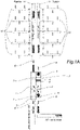
- FIG. 1A a schematic view of an embodiment of the ventilation system for a building comprising a return installation and a supply installation.
- the recovery installation comprises a system of ducts 10', 11' and valves 8, 9 and a vacuum generator 5 intended to drawing air inside the building and expelling it outside the building.
- the supply installation comprises a system of ducts 10, 11 and valves 8, 9 and an overpressure generator 6 intended to send outside air into the building.
- dampers there are several types of dampers, namely fire dampers 8 and air flow adjustment dampers 9.
- the duct systems show, for each installation, a main duct 11, 11' on which is installed a monobloc 1 (in the first embodiment) as well as a plurality of secondary ducts 10, 10' connected to the main conduit 11, 11' and supplying/supplied by various floors/rooms/regions of the building.
- the vacuum generator 5 and the overpressure generator 6 are housed in the same double-flow monoblock 1 comprising a pulse flow 3, 7, 6 and a return flow 7, 5.
- This monoblock 1 also comprises various other elements such as 'a recuperator 7, filters 2 as well as, in the forced air duct, heat exchangers 4, 4' to heat or cool the air.
- the ventilation system comprises two separate blocks, one on each installation, without recuperator but preferably also having filters 2 as well as, in the forced air duct, heat exchangers 4, 4' for heating or cooling the air .
- the installation of drive and the recovery installation are arranged to be placed in communication by a bypass system 12, so that the vacuum generator 5 of the recovery installation can generate a vacuum in the duct system 10, 11 of the pulse installation.
- the valve systems 8, 9 are arranged to, when directing and concentrating the depression in the duct system 10, 11 of the drive installation where the cleaning work is carried out.
- the bypass system 12 comprises a detachable conduit, such as a sheath, connecting a suction conduit 11' to a pulse conduit 11 downstream of the vacuum generator 5.
- a detachable conduit such as a sheath
- the bypass system 12 is placed between the vacuum generator 5 and the ducts 11, 10 of the pulsation installation to be cleaned, and preferably also between the vacuum generator 5 and the secondary ducts 10 of the suction installation to be cleaned,
- the general ventilation system can also include the integrated bypass system with a valve inside to use it or not whether the system is cleaned or not.
- the second aspect of the invention is the method of cleaning the ventilation system described above.
- This method firstly, but optionally, comprises a preliminary step of shutting down the vacuum and overpressure generators. This for more security.
- the method comprises a step of setting up a bypass system between the supply installation and the return installation in order to put in fluidic communication, via the installation of a conduit or a sheath or simply, if the system is permanent, via the opening of a valve for example.
- a first step of actuating the first valve systems is implemented to cut the communication between the suction ducts and the vacuum generator and a second step of actuating the second valve systems to direct and concentrate a vacuum in a first duct system of the supply installation where the cleaning work is carried out.
- the vacuum generator is controlled so as to generate the desired vacuum in the conduit chosen previously.
- the second step of actuating the second valve systems and the generator control step are repeated for each duct of the supply installation where the cleaning work is carried out.
- the method comprises a step of brushing the ducts where the cleaning work is carried out prior to the step of checking the generator.
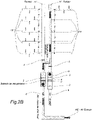
- the figure 3A and 3B represent a specific example of a supply installation with the possibility (slaved closing damper) of injecting part of the rolling air.
- the possibility slaved closing damper
- This technique makes it possible to place the installation under negative pressure and to discharge the stale air to the outside.
- the Figure 3A shows the normal operation of the supply system with the possibility of re-injecting a small quantity of running air into the supply system.
- the Figure 3B shows the use of fire dampers and closing dampers (dampers) to guide and concentrate the vacuum on the duct to be cleaned.
- This device is repeated for all the branches, connecting them as the work progresses, until all the supply ducts in the building have been treated.
Description
La présente invention se rapporte à un dispositif et un procédé de nettoyage pour des installations de ventilation et de climatisation, et plus particulièrement pour des installations de renouvellement d'air.The present invention relates to a cleaning device and method for ventilation and air conditioning installations, and more particularly for air renewal installations.
De nos jours, tous les bâtiments comprennent des systèmes de renouvellement d'air pour procurer de l'air frais et propre à ses occupants. Le principe de fonctionnement général des systèmes de renouvellement d'air dans un bâtiment ou dans un local, comprend des monoblocs double flux comprenant un flux dit de pulsion et un flux dit de reprise. Ces monoblocs permettent d'une part, d'apporter une quantité d'air traité grâce à de l'air pulsé via le flux de pulsion, et d'autre part, d'en retirer, de préférence simultanément, la même quantité d'air vicié, appelé air repris, via le flux de reprise.Today, all buildings include air exchange systems to provide fresh, clean air to its occupants. The general operating principle of air renewal systems in a building or in a room, comprises dual-flow monoblocs comprising a so-called supply flow and a so-called return flow. These monoblocs make it possible, on the one hand, to provide a quantity of treated air thanks to the air pulsated via the pulse flow, and on the other hand, to withdraw, preferably simultaneously, the same quantity of air. stale air, called return air, via the return flow.
Comme tout élément de ventilation, ces flux emmagasinent de la poussière et autres saletés au fil du temps et nécessitent un nettoyage régulier.Like any ventilation element, these flows accumulate dust and other dirt over time and require regular cleaning.
Le document
Le nettoyage à sec des installations de ventilation est en général réalisé par un système de brosses rotatives qui permettent de décoller, par une action mécanique, les poussières emmagasinées dans les systèmes de ventilation.The dry cleaning of ventilation systems is generally carried out by a system of rotating brushes which make it possible to take off, by a mechanical action, the dust stored in the ventilation systems.
Parallèlement, dans le cas d'une installation d'extraction c'est à dire dans les conduits servant au flux de reprise, une dépression, c'est-à-dire une aspiration, est utilisée pour récupérer les poussières soulevées par le brossage pour être évacuées et récupérer sur les filtres du monobloc de reprise qui peuvent être ensuite renouvelés. Cela permet de nettoyer convenablement les installations d'extraction.At the same time, in the case of an extraction installation, i.e. in the ducts used for the return flow, depression, i.e. suction, is used to recover the dust raised by the brushing to be evacuated and recovered on the return monoblock filters which can then be renewed. This makes it possible to properly clean the extraction installations.
En revanche, en ce qui concerne les installations de pulsion servant de conduits au flux de pulsion, cette technique n'est pas possible étant donné que la surpression qui est générée dans les gaines rejetterait les poussières soulevées par le brossage dans les locaux desservis de l'immeuble.On the other hand, with regard to the supply installations serving as ducts for the supply flow, this technique is not possible given that the overpressure which is generated in the ducts would reject the dust raised by the brushing in the premises served by the 'building.
De même, dans l'hypothèse que ces nettoyages soient entrepris avec une installation à l'arrêt, les poussières soulevées ne pourraient pas être évacuées et resteraient en suspension dans les gaines. Dans ce cas, lors de la remise en service de la ventilation, les poussières seraient rejetées dans les locaux et les contamineraient.Similarly, in the event that these cleanings are undertaken with the installation stopped, the dust raised could not be evacuated and would remain in suspension in the ducts. In this case, when the ventilation is put back into service, the dust would be released into the rooms and contaminate them.
Alternativement, une seconde hypothèse consisterait à nettoyer les installations de pulsion en maintenant l'installation en marche, dans ce cas, les poussières seront propulsées, là aussi, dans les locaux desservis et ne résoudrait pas le problème.Alternatively, a second hypothesis would consist in cleaning the expulsion installations by keeping the installation running, in this case, the dust will be propelled, there too, into the premises served and would not solve the problem.
Il apparait donc clairement qu'il existe une difficulté majeure dans le nettoyage des gaines de ventilation en surpression, c'est-à-dire pour les flux d'air pulsé. La solution idéale consisterait à brosser les surfaces des gaines en évitant que les poussières soulevées ne s'échappent à l'intérieur du bâtiment et contaminent les locaux ventilés.It therefore clearly appears that there is a major difficulty in cleaning overpressure ventilation ducts, that is to say for pulsed air flows. The ideal solution would consist of brushing the surfaces of the ducts, preventing the dust raised from escaping inside the building and contaminating the ventilated rooms.
Un objet de la présente invention est donc de résoudre les problèmes décrits ci-dessus, et plus particulièrement de fournir un système et un procédé de nettoyage de système d'aération, notamment de renouvellement d'air, permettant de nettoyer les installations d'air pulsé sans risquer une propagation des poussières à l'intérieur du bâtiment.An object of the present invention is therefore to solve the problems described above, and more particularly to provide a system and a method for cleaning an aeration system, in particular for air renewal, making it possible to clean the air installations pulsed without risking the spread of dust inside the building.
A cet effet, un premier aspect de la présente invention se rapporte à un système de ventilation pour un bâtiment , tel que défini en revendication 1.To this end, a first aspect of the present invention relates to a ventilation system for a building, as defined in
Selon un mode de réalisation préféré, le générateur de dépression et le générateur de surpression sont logés dans un même monobloc double flux comprenant un flux de pulsion et un flux de reprise.According to a preferred embodiment, the vacuum generator and the overpressure generator are housed in the same dual-flow monoblock comprising a drive flow and a return flow.
De manière avantageuse, les systèmes de clapets comprennent des clapets coupe-feu et/ou des clapets de réglages de débits d'air.Advantageously, the damper systems include fire dampers and/or air flow adjustment dampers.
De manière avantageuse, lors d'un nettoyage de l'installation d'aspiration du système de ventilation, les systèmes de clapets sont agencés pour, lors de diriger et concentrer la dépression dans le système de conduits de l'installation d'aspiration où les travaux de nettoyage sont réalisés.Advantageously, during cleaning of the suction installation of the ventilation system, the valve systems are arranged to, when directing and concentrating the depression in the duct system of the suction installation where the cleaning work is carried out.
Selon un mode de réalisation préféré, le système de dérivation comprend un conduit détachable reliant un conduit d'aspiration à un conduit de pulsion en amont du générateur de dépression.According to a preferred embodiment, the bypass system comprises a detachable conduit connecting a suction conduit to a supply conduit upstream of the vacuum generator.
De préférence, le système de ventilation comprend le système de dérivation intégré.Preferably, the ventilation system includes the integrated bypass system.
Selon un deuxième aspect, la présente invention vise un procédé de nettoyage d'un système de ventilation du premier aspect de l'invention, comprenant une étape de mise en place d'un système de dérivation entre l'installation de pulsion et l'installation de reprise afin de les mettre en communication fluidique, une première étape d'actionnement de systèmes de premiers clapets pour couper la communication entre les conduits d'aspiration et le générateur de dépression, une seconde étape d'actionnement de systèmes de seconds clapets pour diriger et concentrer une dépression dans un premier système de conduits de l'installation de pulsion où les travaux de nettoyage sont réalisés, et une étape de contrôle du générateur de dépression de sorte à générer ladite dépression.According to a second aspect, the present invention relates to a method for cleaning a ventilation system of the first aspect of the invention, comprising a step of setting up a bypass system between the pulsion installation and the installation recovery in order to put them in fluid communication, a first step of actuating systems of first valves to cut the communication between the suction ducts and the vacuum generator, a second step of actuating systems of second valves to direct and concentrating a vacuum in a first duct system of the drive installation where the cleaning work is carried out, and a step of controlling the vacuum generator so as to generate said vacuum.
De manière avantageuse, le procédé de nettoyage comprend en outre une étape préliminaire d'arrêt des générateurs de dépression et de surpressionAdvantageously, the cleaning method further comprises a preliminary step of shutting down the vacuum and overpressure generators
De préférence, la seconde étape d'actionnement des systèmes de seconds clapets et l'étape de contrôle du générateur sont répétées pour chaque conduit de l'installation de pulsion où les travaux de nettoyage sont réalisésPreferably, the second step of actuating the second valve systems and the step of controlling the generator are repeated for each conduit of the supply installation where the cleaning work is carried out.
Selon un mode de réalisation préféré, le procédé de nettoyage comprend en outre une étape de brossage des conduits où les travaux de nettoyage sont réalisés antérieure à l'étape de contrôle du générateur.According to a preferred embodiment, the cleaning method also comprises a step of brushing the ducts where the cleaning work is carried out prior to the step of controlling the generator.
Comme on peut le voir, la présente invention se rapporte à un système et à un procédé consistant à mettre l'installation de pulsion en dépression afin de la nettoyer aussi facilement qu'une installation de reprise.As can be seen, the present invention relates to a system and a method consisting in placing the pulsion installation under vacuum in order to clean it as easily as a recovery installation.
Toutefois, le débit d'air élevé de certaines installations ne permet pas l'utilisation d'aspirateur ou de machine externe pour réaliser une dépression suffisante permettant l'évacuation des poussières soulevées. Ce type de technique n'est en effet valable que pour des petites débits et surfaces accessibles par des aspirateurs industriels, pas pour des installations d'immeuble, par exemple.However, the high air flow of certain installations does not allow the use of a vacuum cleaner or an external machine to create a sufficient depression allowing the evacuation of the raised dust. This type of technique is in fact only valid for small flows and surfaces accessible by industrial vacuum cleaners, not for building installations, for example.
Pour contourner cette difficulté technique, la présente invention utilise la dépression du monobloc de reprise de l'installation traitée (même débit) pour créer une dépression suffisante qui puisse mettre toute l'installation de pulsion en dépression (débit d'air pulsion et reprise équivalent).To circumvent this technical difficulty, the present invention uses the depression of the return monobloc of the treated installation (same flow) to create a sufficient depression which can put the entire drive installation in depression (drive and recovery air flow equivalent ).
Pour mettre en œuvre cette technique, une dérivation est réalisée entre les gaines de pulsion et les gaines de reprise afin de créer une communication fluidique entre les deux installations, celle de reprise et celle puisée. Egalement, la présente invention utilise les clapets coupe-feu et les clapets de réglages de débits d'air pour diriger et concentrer la dépression sur la branche sur laquelle les travaux de nettoyage sont réalisés.To implement this technique, a derivation is made between the impulse sheaths and the return sheaths in order to create a fluidic communication between the two installations, that of recovery and that drawn. Also, the present invention uses the fire dampers and the air flow adjustment dampers to direct and concentrate the vacuum on the branch on which the cleaning work is carried out.
La technique actuelle permet également de raccorder un ventilateur centrifuge posé sur roulette pour créer une dépression.The current technique also makes it possible to connect a centrifugal fan placed on wheels to create a depression.
Alternativement il est possible de poser sur roulette un ventilateur ayant un débit équivalent aux installations traitées pour les nettoyer.Alternatively, it is possible to place a fan on rollers with a flow rate equivalent to the installations treated to clean them.
Toutefois, les installations desservant des gros bâtiments (usines, hôpitaux, industrie, etc.) traitent des volumes d'air qui sont largement au-dessus des volumes traités par des ventilateurs mobiles.However, installations serving large buildings (factories, hospitals, industry, etc.) deal with volumes of air which are far above the volumes handled by mobile fans.
La technique de la dérivation peut être mise en œuvre pour tout type d'installation, quel que soit le volume traité.The bypass technique can be implemented for any type of installation, whatever the volume treated.
Mieux encore, elle permet de diriger et de concentrer la dépression directement sur la branche de l'installation que l'on souhaite nettoyer, et ce sans aucun risque de polluer ou de contaminer les locaux desservis compte tenu de la dépression à laquelle nous soumettons la section traitée.Better still, it makes it possible to direct and concentrate the depression directly on the branch of the installation that one wishes to clean, and this without any risk of polluting or contaminating the premises served, taking into account the depression to which we subject the processed section.
D'autres avantages, buts et caractéristiques particulières de l'invention ressortiront de la description non limitative qui suit d'au moins un mode de réalisation particulier du dispositif et du procédé objets de la présente invention, en regard des dessins annexés, dans lesquels :
- les
figures 1A à 1C représentent, schématiquement un système de ventilation pour un bâtiment selon un premier mode de réalisation de l'invention et son procédé de nettoyage, et - les
figures 2A et2B représentent, schématiquement, un système de ventilation pour un bâtiment selon un second mode de réalisation de l'invention et son procédé de nettoyage. - les
figures 3A et3B représentent, schématiquement, un système de ventilation pour un bâtiment selon un troisième mode de réalisation de l'invention et son procédé de nettoyage.
- them
figures 1A to 1C schematically represent a ventilation system for a building according to a first embodiment of the invention and its cleaning method, and - them
figure 2A and2B represent, schematically, a ventilation system for a building according to a second embodiment of the invention and its cleaning method. - them
figure 3A and3B represent, schematically, a ventilation system for a building according to a third embodiment of the invention and its cleaning method.
La présente description est donnée à titre non limitatif, chaque caractéristique d'un mode de réalisation pouvant être combinée à toute autre caractéristique de tout autre mode de réalisation de manière avantageuse. On note dès à présent que les figures ne sont pas à l'échelle.This description is given on a non-limiting basis, each characteristic of an embodiment being able to be combined with any other characteristic of any other embodiment in an advantageous manner. Note that the figures are not to scale.
On observe, sur la
Comme on peut le voir, l'installation de reprise comprend un système de conduits 10', 11' et de clapets 8, 9 et un générateur de dépression 5 destinés à aspirer de l'air intérieur au bâtiment et l'expulser hors du bâtiment. De son côté, l'installation de pulsion comprend un système de conduits 10, 11 et de clapets 8, 9 et un générateur de surpression 6 destinés à envoyer de l'air extérieur dans le bâtiment. Il est à noter qu'il existe plusieurs types de clapets, à savoir des clapets coupe-feu 8 et des clapets de réglages de débits d'air 9.As can be seen, the recovery installation comprises a system of ducts 10', 11' and
En effet, comme on peut le voir, les systèmes de conduits montrent, pour chaque installation un conduit principal 11, 11' sur lequel est installé un monobloc 1 (dans le premier mode de réalisation) ainsi qu'une pluralité de conduits secondaires 10, 10' reliés au conduit principal 11, 11' et alimentant/alimenté par divers étages/pièces/régions du bâtiment.Indeed, as can be seen, the duct systems show, for each installation, a
Dans le premier mode de réalisation représenté sur les
Dans le second mode de réalisation représenté aux
Selon l'invention, comme représenté sur les
De préférence, le système de dérivation 12 comprend un conduit détachable, tel qu'une gaine, reliant un conduit d'aspiration 11' à un conduit de pulsion 11 en aval du générateur de déprèssion 5. Par « en aval du générateur de dépression » il doit être compris évidemment que le système de dérivation 12 est placé entre le générateur de dépression 5 et les conduits 11, 10 de l'installation de pulsation à nettoyer, et de préférence également entre le générateur de dépression 5 et les conduits secondaires 10 de l'installation d'aspiration à nettoyer,Preferably, the
Enfin, afin de simplifier le tout, le système de ventilation général peut également comprendre le système de dérivation intégré avec un clapet à l'intérieur pour ou non l'utiliser que l'on nettoie le système ou pas.Finally, in order to simplify everything, the general ventilation system can also include the integrated bypass system with a valve inside to use it or not whether the system is cleaned or not.
Le second aspect de l'invention est le procédé de nettoyage du système de ventilation décrit plus haut. Ce procédé comprend d'abord, mais optionnellement, une étape préliminaire d'arrêt des générateurs de dépression et de surpression. Cela pour plus de sécurité.The second aspect of the invention is the method of cleaning the ventilation system described above. This method firstly, but optionally, comprises a preliminary step of shutting down the vacuum and overpressure generators. This for more security.
Par la suite, le procédé comprend une étape de mise en place d'un système de dérivation entre l'installation de pulsion et l'installation de reprise afin de les mettre en communication fluidique, via l'installation d'un conduit ou d'une gaine ou simplement, si le système est permanent, via l'ouverture d'un clapet par exemple.Subsequently, the method comprises a step of setting up a bypass system between the supply installation and the return installation in order to put in fluidic communication, via the installation of a conduit or a sheath or simply, if the system is permanent, via the opening of a valve for example.
Ensuite, on met en œuvre une première étape d'actionnement des systèmes de premiers clapets pour couper la communication entre les conduits d'aspiration et le générateur de dépression et une seconde étape d'actionnement des systèmes de seconds clapets pour diriger et concentrer une dépression dans un premier système de conduits de l'installation de pulsion où les travaux de nettoyage sont réalisés. Enfin, on contrôle le générateur de dépression sorte à générer la dépression souhaitée dans le conduit choisi précédemment.Then, a first step of actuating the first valve systems is implemented to cut the communication between the suction ducts and the vacuum generator and a second step of actuating the second valve systems to direct and concentrate a vacuum in a first duct system of the supply installation where the cleaning work is carried out. Finally, the vacuum generator is controlled so as to generate the desired vacuum in the conduit chosen previously.
Une fois le conduit propre, on répète la seconde étape d'actionnement des systèmes de seconds clapets et l'étape de contrôle du générateur pour chaque conduit de l'installation de pulsion où les travaux de nettoyage sont réalisés.Once the duct is clean, the second step of actuating the second valve systems and the generator control step are repeated for each duct of the supply installation where the cleaning work is carried out.
Optionnellement comme indiqué plus haut, le procédé comprend une étape de brossage des conduits où les travaux de nettoyage sont réalisés antérieure à l'étape de contrôle du générateur.Optionally, as indicated above, the method comprises a step of brushing the ducts where the cleaning work is carried out prior to the step of checking the generator.
Les
Cette technique permet de mettre l'installation en dépression et de refouler l'air vicié vers l'extérieur.This technique makes it possible to place the installation under negative pressure and to discharge the stale air to the outside.
La
La
L'installation de la dérivation sur la gaine d'air de roulement qui permet de guider l'air extrait jusqu'au ventilateur (en lieu et place de l'amenée d'air neuf).The installation of the bypass on the running air duct which allows the extracted air to be guided to the fan (instead of the fresh air supply).
Enfin, l'utilisation de la gaine de distribution pour refouler l'air vicié vers l'extérieur par le biais de la dérivation.Finally, the use of the distribution duct to discharge stale air to the outside through the bypass.
Ce dispositif est répété pour toutes les branches en les connectant au fur et à mesure de l'avancement des travaux, jusqu'à traiter toutes les gaines de pulsion du bâtiment.This device is repeated for all the branches, connecting them as the work progresses, until all the supply ducts in the building have been treated.
Claims (11)
- A ventilation system for a building, comprising a return installation and a pulse installation,the return installation comprising a system of ducts (10', 11') and valves (8, 9) and a vacuum generator (5) intended to suck air inside the building,the pulse installation comprising a system of ducts (10, 11) and valves (8, 9) and a booster generator (6) intended to send outside air into the building,characterized in that, during cleaning of the pulse installation of the ventilation system, said valves (8, 9) of the return installation are arranged to cut off the communication between the suction ducts (10', 11') and the vacuum generator (5),said valves (8, 9) of the pulse installation are arranged to direct and concentrate a vacuum in a first system of ducts (10) of the pulse installation where the cleaning works should be carried out, andthe pulse installation and the return installation are arranged to be put into communication by a bypass system (12), so that the vacuum generator (5) of the return installation could generate a vacuum in the system of ducts (10, 11) of the pulse installation.
- The ventilation system according to claim 1, characterized in that the vacuum generator (5) and the booster generator (6) are housed in the same double-flow monoblock (1) comprising a pulse flow and a return flow.
- The ventilation system according to claims 1 or 2, characterized in that the systems of valves comprise fire-damper valves (8) and/or air flow adjusting valves (9).
- The ventilation system according to claim 1 to 3, characterized in that, during cleaning of the suction installation of the ventilation system, the systems of valves (8, 9) are arranged to direct and concentrate the vacuum in the system of ducts (10', 11') of the suction installation where the cleaning works are carried out.
- The ventilation system according to any one of claims 1 to 4, characterized in that the bypass system (12) comprises a detachable duct connecting a suction duct (11') to a pulse duct (11) upstream of the vacuum generator (5).
- The ventilation system according to any one of claims 1 to 5, characterized in that it comprises the bypass system (12) integrated.
- A method for cleaning a ventilation system according to any one of claims 1 to 6, comprising- a step of setting up the bypass system (12) between the pulse installation and the return installation in order to put them into fluid communication,- a first step of actuating systems of first valves (8) to cut off the communication between the suction ducts (10', 11') and the vacuum generator (5),- a second step of actuating systems of second valves (8, 9) to direct and concentrate a vacuum in a first system of ducts (10) of the pulse installation where the cleaning works are carried out, and- a step of controlling the vacuum generator (5) so as to generate said vacuum.
- The method for cleaning a ventilation system according to claim 7, characterized in that it further comprises a preliminary step of stopping the vacuum and booster generators (5, 6).
- The method for cleaning a ventilation system according to claim 7 or 8, characterized in that the second step of actuating the systems of second valves (8, 9) and the step of controlling the generator are repeated for each duct of the pulse installation where the cleaning works are carried out.
- The method for cleaning a ventilation system according to claim 7, 8 or 9, characterized in that it further comprises a step of brushing the ducts where the cleaning works are carried out prior to the step of controlling the generator.
- The method for cleaning a ventilation system according to any one of claims 7 to 10, characterized in that the two steps of actuating valves (8, 9) are simultaneous.
Applications Claiming Priority (1)
| Application Number | Priority Date | Filing Date | Title |
|---|---|---|---|
| EP19170021 | 2019-04-18 |
Publications (2)
| Publication Number | Publication Date |
|---|---|
| EP3726155A1 EP3726155A1 (en) | 2020-10-21 |
| EP3726155B1 true EP3726155B1 (en) | 2022-07-13 |
Family
ID=66239778
Family Applications (1)
| Application Number | Title | Priority Date | Filing Date |
|---|---|---|---|
| EP20170109.1A Active EP3726155B1 (en) | 2019-04-18 | 2020-04-17 | Ventilation system and method for cleaning the same |
Country Status (1)
| Country | Link |
|---|---|
| EP (1) | EP3726155B1 (en) |
Family Cites Families (5)
| Publication number | Priority date | Publication date | Assignee | Title |
|---|---|---|---|---|
| US4589476A (en) * | 1985-05-16 | 1986-05-20 | Erling Berner | Air ventilation and filtration apparatus |
| DE102010011918B4 (en) * | 2010-03-18 | 2019-01-31 | Ltg Aktiengesellschaft | Method for operating an air-conditioning device |
| AT510003B1 (en) * | 2010-07-15 | 2012-01-15 | Troges Gmbh | VENTILATION UNIT |
| FR3003017B1 (en) * | 2013-03-05 | 2016-11-11 | Eric Fenioux | VENTILATION SHEATH FOR FACILITIES FOR ANIMALS AND VENTILATION SYSTEM COMPRISING THE SAME |
| DE102015108698A1 (en) * | 2015-06-02 | 2016-12-08 | Vorwerk & Co. Interholding Gmbh | Air purifier for cleaning room air and fresh air |
-
2020
- 2020-04-17 EP EP20170109.1A patent/EP3726155B1/en active Active
Also Published As
| Publication number | Publication date |
|---|---|
| EP3726155A1 (en) | 2020-10-21 |
Similar Documents
| Publication | Publication Date | Title |
|---|---|---|
| US20180050371A1 (en) | Fume evacuation system | |
| JP2010151132A (en) | System for removing foreign substance from airflow inflowing into turbo machine and method thereof | |
| FR3002244A3 (en) | MAN BLOWER | |
| JP6232650B1 (en) | Pipe cleaning device and pipe cleaning method | |
| EP3726155B1 (en) | Ventilation system and method for cleaning the same | |
| FR2804204A1 (en) | Cooking byproduct discharge method for use in restaurants, involves increasing volume of air ejected from cooking apparatus to exterior of plant, when temperature of environment exceeds desired level | |
| WO2014010535A2 (en) | Device for moving inside pipe and performing task | |
| HK1127743A1 (en) | Dust suction device with self-cleaning of the filters | |
| KR101698173B1 (en) | Robot for cleaning dust in pipe | |
| TWI644726B (en) | Heat reactivated adsorbent gas fractionator and process | |
| JP2001500943A (en) | Steam turbine, steam turbine equipment, and cooling method for steam turbine | |
| FR3032917A1 (en) | AIR CONDITIONING MODULE OF A MOTOR VEHICLE | |
| JP4839815B2 (en) | Range food | |
| JP6220346B2 (en) | Pressure masking system and method of use thereof | |
| JP6497770B2 (en) | Oil mist collection structure | |
| US10844574B2 (en) | Mobile vacuum system | |
| JP3108228U (en) | Vacuum pump device | |
| JP4369767B2 (en) | Method and apparatus for isolating chemical agent contaminated area | |
| JP2017223374A (en) | Air conditioner and air conditioning system | |
| EP3119927B1 (en) | Apparatus for treating gases from electrolytic cells for the production of aluminium | |
| EP2935897B1 (en) | Sealing assembly for turbomachine | |
| CN114570708B (en) | Watch cleaning machine and watch cleaning method | |
| FR3074568B1 (en) | UPSTREAM CHICANE VENTILATION BOX | |
| EP2436991A1 (en) | Air-treatment hood in a kitchen and method for treating air in a kitchen equipped with such a hood | |
| JP2001038315A (en) | Rinsing of pipeline |
Legal Events
| Date | Code | Title | Description |
|---|---|---|---|
| PUAI | Public reference made under article 153(3) epc to a published international application that has entered the european phase |
Free format text: ORIGINAL CODE: 0009012 |
|
| STAA | Information on the status of an ep patent application or granted ep patent |
Free format text: STATUS: THE APPLICATION HAS BEEN PUBLISHED |
|
| AK | Designated contracting states |
Kind code of ref document: A1 Designated state(s): AL AT BE BG CH CY CZ DE DK EE ES FI FR GB GR HR HU IE IS IT LI LT LU LV MC MK MT NL NO PL PT RO RS SE SI SK SM TR |
|
| AX | Request for extension of the european patent |
Extension state: BA ME |
|
| STAA | Information on the status of an ep patent application or granted ep patent |
Free format text: STATUS: REQUEST FOR EXAMINATION WAS MADE |
|
| 17P | Request for examination filed |
Effective date: 20210413 |
|
| RBV | Designated contracting states (corrected) |
Designated state(s): AL AT BE BG CH CY CZ DE DK EE ES FI FR GB GR HR HU IE IS IT LI LT LU LV MC MK MT NL NO PL PT RO RS SE SI SK SM TR |
|
| GRAP | Despatch of communication of intention to grant a patent |
Free format text: ORIGINAL CODE: EPIDOSNIGR1 |
|
| STAA | Information on the status of an ep patent application or granted ep patent |
Free format text: STATUS: GRANT OF PATENT IS INTENDED |
|
| INTG | Intention to grant announced |
Effective date: 20220203 |
|
| GRAS | Grant fee paid |
Free format text: ORIGINAL CODE: EPIDOSNIGR3 |
|
| GRAA | (expected) grant |
Free format text: ORIGINAL CODE: 0009210 |
|
| STAA | Information on the status of an ep patent application or granted ep patent |
Free format text: STATUS: THE PATENT HAS BEEN GRANTED |
|
| AK | Designated contracting states |
Kind code of ref document: B1 Designated state(s): AL AT BE BG CH CY CZ DE DK EE ES FI FR GB GR HR HU IE IS IT LI LT LU LV MC MK MT NL NO PL PT RO RS SE SI SK SM TR |
|
| REG | Reference to a national code |
Ref country code: CH Ref legal event code: EP |
|
| REG | Reference to a national code |
Ref country code: DE Ref legal event code: R096 Ref document number: 602020003954 Country of ref document: DE |
|
| REG | Reference to a national code |
Ref country code: AT Ref legal event code: REF Ref document number: 1504468 Country of ref document: AT Kind code of ref document: T Effective date: 20220815 |
|
| REG | Reference to a national code |
Ref country code: IE Ref legal event code: FG4D Free format text: LANGUAGE OF EP DOCUMENT: FRENCH |
|
| REG | Reference to a national code |
Ref country code: LT Ref legal event code: MG9D |
|
| REG | Reference to a national code |
Ref country code: NL Ref legal event code: MP Effective date: 20220713 |
|
| PG25 | Lapsed in a contracting state [announced via postgrant information from national office to epo] |
Ref country code: SE Free format text: LAPSE BECAUSE OF FAILURE TO SUBMIT A TRANSLATION OF THE DESCRIPTION OR TO PAY THE FEE WITHIN THE PRESCRIBED TIME-LIMIT Effective date: 20220713 Ref country code: RS Free format text: LAPSE BECAUSE OF FAILURE TO SUBMIT A TRANSLATION OF THE DESCRIPTION OR TO PAY THE FEE WITHIN THE PRESCRIBED TIME-LIMIT Effective date: 20220713 Ref country code: PT Free format text: LAPSE BECAUSE OF FAILURE TO SUBMIT A TRANSLATION OF THE DESCRIPTION OR TO PAY THE FEE WITHIN THE PRESCRIBED TIME-LIMIT Effective date: 20221114 Ref country code: NO Free format text: LAPSE BECAUSE OF FAILURE TO SUBMIT A TRANSLATION OF THE DESCRIPTION OR TO PAY THE FEE WITHIN THE PRESCRIBED TIME-LIMIT Effective date: 20221013 Ref country code: NL Free format text: LAPSE BECAUSE OF FAILURE TO SUBMIT A TRANSLATION OF THE DESCRIPTION OR TO PAY THE FEE WITHIN THE PRESCRIBED TIME-LIMIT Effective date: 20220713 Ref country code: LV Free format text: LAPSE BECAUSE OF FAILURE TO SUBMIT A TRANSLATION OF THE DESCRIPTION OR TO PAY THE FEE WITHIN THE PRESCRIBED TIME-LIMIT Effective date: 20220713 Ref country code: LT Free format text: LAPSE BECAUSE OF FAILURE TO SUBMIT A TRANSLATION OF THE DESCRIPTION OR TO PAY THE FEE WITHIN THE PRESCRIBED TIME-LIMIT Effective date: 20220713 Ref country code: FI Free format text: LAPSE BECAUSE OF FAILURE TO SUBMIT A TRANSLATION OF THE DESCRIPTION OR TO PAY THE FEE WITHIN THE PRESCRIBED TIME-LIMIT Effective date: 20220713 Ref country code: ES Free format text: LAPSE BECAUSE OF FAILURE TO SUBMIT A TRANSLATION OF THE DESCRIPTION OR TO PAY THE FEE WITHIN THE PRESCRIBED TIME-LIMIT Effective date: 20220713 |
|
| REG | Reference to a national code |
Ref country code: AT Ref legal event code: MK05 Ref document number: 1504468 Country of ref document: AT Kind code of ref document: T Effective date: 20220713 |
|
| PG25 | Lapsed in a contracting state [announced via postgrant information from national office to epo] |
Ref country code: PL Free format text: LAPSE BECAUSE OF FAILURE TO SUBMIT A TRANSLATION OF THE DESCRIPTION OR TO PAY THE FEE WITHIN THE PRESCRIBED TIME-LIMIT Effective date: 20220713 Ref country code: IS Free format text: LAPSE BECAUSE OF FAILURE TO SUBMIT A TRANSLATION OF THE DESCRIPTION OR TO PAY THE FEE WITHIN THE PRESCRIBED TIME-LIMIT Effective date: 20221113 Ref country code: HR Free format text: LAPSE BECAUSE OF FAILURE TO SUBMIT A TRANSLATION OF THE DESCRIPTION OR TO PAY THE FEE WITHIN THE PRESCRIBED TIME-LIMIT Effective date: 20220713 Ref country code: GR Free format text: LAPSE BECAUSE OF FAILURE TO SUBMIT A TRANSLATION OF THE DESCRIPTION OR TO PAY THE FEE WITHIN THE PRESCRIBED TIME-LIMIT Effective date: 20221014 |
|
| REG | Reference to a national code |
Ref country code: DE Ref legal event code: R097 Ref document number: 602020003954 Country of ref document: DE |
|
| PG25 | Lapsed in a contracting state [announced via postgrant information from national office to epo] |
Ref country code: SM Free format text: LAPSE BECAUSE OF FAILURE TO SUBMIT A TRANSLATION OF THE DESCRIPTION OR TO PAY THE FEE WITHIN THE PRESCRIBED TIME-LIMIT Effective date: 20220713 Ref country code: RO Free format text: LAPSE BECAUSE OF FAILURE TO SUBMIT A TRANSLATION OF THE DESCRIPTION OR TO PAY THE FEE WITHIN THE PRESCRIBED TIME-LIMIT Effective date: 20220713 Ref country code: DK Free format text: LAPSE BECAUSE OF FAILURE TO SUBMIT A TRANSLATION OF THE DESCRIPTION OR TO PAY THE FEE WITHIN THE PRESCRIBED TIME-LIMIT Effective date: 20220713 Ref country code: CZ Free format text: LAPSE BECAUSE OF FAILURE TO SUBMIT A TRANSLATION OF THE DESCRIPTION OR TO PAY THE FEE WITHIN THE PRESCRIBED TIME-LIMIT Effective date: 20220713 Ref country code: AT Free format text: LAPSE BECAUSE OF FAILURE TO SUBMIT A TRANSLATION OF THE DESCRIPTION OR TO PAY THE FEE WITHIN THE PRESCRIBED TIME-LIMIT Effective date: 20220713 |
|
| PLBE | No opposition filed within time limit |
Free format text: ORIGINAL CODE: 0009261 |
|
| STAA | Information on the status of an ep patent application or granted ep patent |
Free format text: STATUS: NO OPPOSITION FILED WITHIN TIME LIMIT |
|
| PG25 | Lapsed in a contracting state [announced via postgrant information from national office to epo] |
Ref country code: SK Free format text: LAPSE BECAUSE OF FAILURE TO SUBMIT A TRANSLATION OF THE DESCRIPTION OR TO PAY THE FEE WITHIN THE PRESCRIBED TIME-LIMIT Effective date: 20220713 Ref country code: EE Free format text: LAPSE BECAUSE OF FAILURE TO SUBMIT A TRANSLATION OF THE DESCRIPTION OR TO PAY THE FEE WITHIN THE PRESCRIBED TIME-LIMIT Effective date: 20220713 |
|
| 26N | No opposition filed |
Effective date: 20230414 |
|
| PG25 | Lapsed in a contracting state [announced via postgrant information from national office to epo] |
Ref country code: AL Free format text: LAPSE BECAUSE OF FAILURE TO SUBMIT A TRANSLATION OF THE DESCRIPTION OR TO PAY THE FEE WITHIN THE PRESCRIBED TIME-LIMIT Effective date: 20220713 |
|
| PGFP | Annual fee paid to national office [announced via postgrant information from national office to epo] |
Ref country code: FR Payment date: 20230404 Year of fee payment: 4 Ref country code: CH Payment date: 20230502 Year of fee payment: 4 |
|
| PG25 | Lapsed in a contracting state [announced via postgrant information from national office to epo] |
Ref country code: SI Free format text: LAPSE BECAUSE OF FAILURE TO SUBMIT A TRANSLATION OF THE DESCRIPTION OR TO PAY THE FEE WITHIN THE PRESCRIBED TIME-LIMIT Effective date: 20220713 |
|
| REG | Reference to a national code |
Ref country code: DE Ref legal event code: R119 Ref document number: 602020003954 Country of ref document: DE |
|
| PG25 | Lapsed in a contracting state [announced via postgrant information from national office to epo] |
Ref country code: LU Free format text: LAPSE BECAUSE OF NON-PAYMENT OF DUE FEES Effective date: 20230417 |
|
| REG | Reference to a national code |
Ref country code: BE Ref legal event code: MM Effective date: 20230430 |
|
| PG25 | Lapsed in a contracting state [announced via postgrant information from national office to epo] |
Ref country code: MC Free format text: LAPSE BECAUSE OF FAILURE TO SUBMIT A TRANSLATION OF THE DESCRIPTION OR TO PAY THE FEE WITHIN THE PRESCRIBED TIME-LIMIT Effective date: 20220713 |
|
| PG25 | Lapsed in a contracting state [announced via postgrant information from national office to epo] |
Ref country code: MC Free format text: LAPSE BECAUSE OF FAILURE TO SUBMIT A TRANSLATION OF THE DESCRIPTION OR TO PAY THE FEE WITHIN THE PRESCRIBED TIME-LIMIT Effective date: 20220713 Ref country code: IT Free format text: LAPSE BECAUSE OF FAILURE TO SUBMIT A TRANSLATION OF THE DESCRIPTION OR TO PAY THE FEE WITHIN THE PRESCRIBED TIME-LIMIT Effective date: 20220713 Ref country code: DE Free format text: LAPSE BECAUSE OF NON-PAYMENT OF DUE FEES Effective date: 20231103 |
|
| REG | Reference to a national code |
Ref country code: IE Ref legal event code: MM4A |
|
| PG25 | Lapsed in a contracting state [announced via postgrant information from national office to epo] |
Ref country code: BE Free format text: LAPSE BECAUSE OF NON-PAYMENT OF DUE FEES Effective date: 20230430 |
|
| PG25 | Lapsed in a contracting state [announced via postgrant information from national office to epo] |
Ref country code: IE Free format text: LAPSE BECAUSE OF NON-PAYMENT OF DUE FEES Effective date: 20230417 |