EP3726086B1 - Hydraulic clutch assemblies - Google Patents
Hydraulic clutch assemblies Download PDFInfo
- Publication number
- EP3726086B1 EP3726086B1 EP19212094.7A EP19212094A EP3726086B1 EP 3726086 B1 EP3726086 B1 EP 3726086B1 EP 19212094 A EP19212094 A EP 19212094A EP 3726086 B1 EP3726086 B1 EP 3726086B1
- Authority
- EP
- European Patent Office
- Prior art keywords
- shaft
- lubrication
- control pressure
- piston
- backstop
- Prior art date
- Legal status (The legal status is an assumption and is not a legal conclusion. Google has not performed a legal analysis and makes no representation as to the accuracy of the status listed.)
- Active
Links
Images




Classifications
-
- F—MECHANICAL ENGINEERING; LIGHTING; HEATING; WEAPONS; BLASTING
- F16—ENGINEERING ELEMENTS AND UNITS; GENERAL MEASURES FOR PRODUCING AND MAINTAINING EFFECTIVE FUNCTIONING OF MACHINES OR INSTALLATIONS; THERMAL INSULATION IN GENERAL
- F16D—COUPLINGS FOR TRANSMITTING ROTATION; CLUTCHES; BRAKES
- F16D25/00—Fluid-actuated clutches
- F16D25/06—Fluid-actuated clutches in which the fluid actuates a piston incorporated in, i.e. rotating with the clutch
- F16D25/062—Fluid-actuated clutches in which the fluid actuates a piston incorporated in, i.e. rotating with the clutch the clutch having friction surfaces
- F16D25/063—Fluid-actuated clutches in which the fluid actuates a piston incorporated in, i.e. rotating with the clutch the clutch having friction surfaces with clutch members exclusively moving axially
- F16D25/0635—Fluid-actuated clutches in which the fluid actuates a piston incorporated in, i.e. rotating with the clutch the clutch having friction surfaces with clutch members exclusively moving axially with flat friction surfaces, e.g. discs
- F16D25/0638—Fluid-actuated clutches in which the fluid actuates a piston incorporated in, i.e. rotating with the clutch the clutch having friction surfaces with clutch members exclusively moving axially with flat friction surfaces, e.g. discs with more than two discs, e.g. multiple lamellae
-
- F—MECHANICAL ENGINEERING; LIGHTING; HEATING; WEAPONS; BLASTING
- F02—COMBUSTION ENGINES; HOT-GAS OR COMBUSTION-PRODUCT ENGINE PLANTS
- F02C—GAS-TURBINE PLANTS; AIR INTAKES FOR JET-PROPULSION PLANTS; CONTROLLING FUEL SUPPLY IN AIR-BREATHING JET-PROPULSION PLANTS
- F02C7/00—Features, components parts, details or accessories, not provided for in, or of interest apart form groups F02C1/00 - F02C6/00; Air intakes for jet-propulsion plants
- F02C7/36—Power transmission arrangements between the different shafts of the gas turbine plant, or between the gas-turbine plant and the power user
-
- F—MECHANICAL ENGINEERING; LIGHTING; HEATING; WEAPONS; BLASTING
- F16—ENGINEERING ELEMENTS AND UNITS; GENERAL MEASURES FOR PRODUCING AND MAINTAINING EFFECTIVE FUNCTIONING OF MACHINES OR INSTALLATIONS; THERMAL INSULATION IN GENERAL
- F16D—COUPLINGS FOR TRANSMITTING ROTATION; CLUTCHES; BRAKES
- F16D25/00—Fluid-actuated clutches
- F16D25/12—Details not specific to one of the before-mentioned types
- F16D25/123—Details not specific to one of the before-mentioned types in view of cooling and lubrication
-
- F—MECHANICAL ENGINEERING; LIGHTING; HEATING; WEAPONS; BLASTING
- F16—ENGINEERING ELEMENTS AND UNITS; GENERAL MEASURES FOR PRODUCING AND MAINTAINING EFFECTIVE FUNCTIONING OF MACHINES OR INSTALLATIONS; THERMAL INSULATION IN GENERAL
- F16H—GEARING
- F16H57/00—General details of gearing
- F16H57/04—Features relating to lubrication or cooling or heating
- F16H57/042—Guidance of lubricant
- F16H57/0421—Guidance of lubricant on or within the casing, e.g. shields or baffles for collecting lubricant, tubes, pipes, grooves, channels or the like
- F16H57/0426—Means for guiding lubricant into an axial channel of a shaft
-
- F—MECHANICAL ENGINEERING; LIGHTING; HEATING; WEAPONS; BLASTING
- F16—ENGINEERING ELEMENTS AND UNITS; GENERAL MEASURES FOR PRODUCING AND MAINTAINING EFFECTIVE FUNCTIONING OF MACHINES OR INSTALLATIONS; THERMAL INSULATION IN GENERAL
- F16H—GEARING
- F16H57/00—General details of gearing
- F16H57/04—Features relating to lubrication or cooling or heating
- F16H57/042—Guidance of lubricant
- F16H57/043—Guidance of lubricant within rotary parts, e.g. axial channels or radial openings in shafts
-
- F—MECHANICAL ENGINEERING; LIGHTING; HEATING; WEAPONS; BLASTING
- F16—ENGINEERING ELEMENTS AND UNITS; GENERAL MEASURES FOR PRODUCING AND MAINTAINING EFFECTIVE FUNCTIONING OF MACHINES OR INSTALLATIONS; THERMAL INSULATION IN GENERAL
- F16H—GEARING
- F16H57/00—General details of gearing
- F16H57/04—Features relating to lubrication or cooling or heating
- F16H57/0457—Splash lubrication
-
- F—MECHANICAL ENGINEERING; LIGHTING; HEATING; WEAPONS; BLASTING
- F16—ENGINEERING ELEMENTS AND UNITS; GENERAL MEASURES FOR PRODUCING AND MAINTAINING EFFECTIVE FUNCTIONING OF MACHINES OR INSTALLATIONS; THERMAL INSULATION IN GENERAL
- F16L—PIPES; JOINTS OR FITTINGS FOR PIPES; SUPPORTS FOR PIPES, CABLES OR PROTECTIVE TUBING; MEANS FOR THERMAL INSULATION IN GENERAL
- F16L9/00—Rigid pipes
- F16L9/18—Double-walled pipes; Multi-channel pipes or pipe assemblies
- F16L9/19—Multi-channel pipes or pipe assemblies
-
- F—MECHANICAL ENGINEERING; LIGHTING; HEATING; WEAPONS; BLASTING
- F16—ENGINEERING ELEMENTS AND UNITS; GENERAL MEASURES FOR PRODUCING AND MAINTAINING EFFECTIVE FUNCTIONING OF MACHINES OR INSTALLATIONS; THERMAL INSULATION IN GENERAL
- F16D—COUPLINGS FOR TRANSMITTING ROTATION; CLUTCHES; BRAKES
- F16D48/00—External control of clutches
- F16D48/02—Control by fluid pressure
- F16D2048/0209—Control by fluid pressure characterised by fluid valves having control pistons, e.g. spools
-
- F—MECHANICAL ENGINEERING; LIGHTING; HEATING; WEAPONS; BLASTING
- F16—ENGINEERING ELEMENTS AND UNITS; GENERAL MEASURES FOR PRODUCING AND MAINTAINING EFFECTIVE FUNCTIONING OF MACHINES OR INSTALLATIONS; THERMAL INSULATION IN GENERAL
- F16D—COUPLINGS FOR TRANSMITTING ROTATION; CLUTCHES; BRAKES
- F16D48/00—External control of clutches
- F16D48/02—Control by fluid pressure
- F16D48/0206—Control by fluid pressure in a system with a plurality of fluid-actuated clutches
Definitions
- This invention relates to transmission systems, e.g., for aircraft low speed spool turbomachines.
- Moving engine accessories to the low speed spool requires a speed converting transmission to take a large speed ratio and turn it into a tighter speed ratio band.
- One method of doing this is the use of a shifting transmission consisting of clutches that selectively engage different gear ratios. These clutches need to be selectively open or closed such that they can transmit or not transmit torque on a command.
- CN 107 269 743 relates to a hydraulic clutch assembly.
- a hydraulic clutch assembly is defined in claim 1 and includes a shaft defining a shaft channel, one or more hydraulic ports defined through the shaft, and one or more lubrication holes defined through the shaft.
- a porting manifold is disposed at least partially within the shaft channel.
- the porting manifold includes a control pressure path in fluid communication with the one or more hydraulic ports and a lubrication flow path in fluid communication with the one or more lubrication holes.
- the control pressure path and the lubrication path are fluidly isolated in the porting manifold.
- the control pressure path can include a central axial channel defined partially along an axial length of the porting manifold from a control pressure inlet of the porting manifold, and one or more radial channels defined radially from the central axial channel to a respective control pressure outlet of the porting manifold.
- the shaft can include a control pressure annulus in fluid communication with the one or more control pressure outlets of the one or more radial channels.
- the one or more hydraulic ports can be in fluid communication with the control pressure annulus.
- the lubrication flow path can include one or more axial lubrication channels defined at least partially along an axial length of the porting manifold from a lubrication flow inlet of the porting manifold, and one or more radial lubrication channels defined radially from a respective axial lubrication channel to a respective lubrication flow outlet of the porting manifold.
- the shaft can include a lubrication flow annulus in fluid communication with the one or more lubrication flow outlets of the one or more radial channels.
- One or more lubrication holes of the one or more lubrication holes can be in fluid communication with the lubrication flow annulus.
- the porting manifold can include one or more drive tabs configured to limit insertion into the shaft.
- the porting manifold can include a plurality of seal grooves.
- the assembly can include a plurality of manifold seals disposed within the seal grooves and configured to fluidly isolate the control pressure from the lubrication flow within the shaft.
- the assembly includes a backstop and a piston disposed on the shaft.
- the backstop is fixed to the shaft and the piston is slidably engaged to the shaft to move relative to the shaft and the backstop.
- the backstop and the piston define a hydraulic cavity therebetween in fluid communication with the one or more hydraulic ports of the shaft.
- the piston is configured to move between a retracted position and an engaged position wherein the piston engages a clutch pack.
- the piston is slidably sealed to an outer diameter of the backstop.
- the assembly includes a balance dam fixed to the piston and disposed around a portion of the backstop to define a lubrication cavity between a back side of the backstop and the balance dam.
- a spring can be disposed between the back side of the backstop and the balance dam to bias the piston to the retracted position.
- At least one lubrication hole of the one or more lubrication holes can be defined through the shaft and through the backstop to fluidly communicate with the lubrication cavity.
- the assembly can include an inner clutch basket rotationally fixed to the shaft to turn with the shaft, an outer clutch basket rotatably mounted on the shaft to rotate relative to the shaft, and a clutch pack disposed between the inner clutch basket and the outer clutch basket.
- the clutch pack can be configured to be compressed by the piston in the engaged position to engage the inner clutch basket to the outer clutch basket to cause the outer clutch basket to rotate with the inner clutch basket and the shaft.
- a method is defined in claim 8 and includes providing a hydraulic control pressure through a shaft of a transmission to control a position of a piston of a clutch assembly to selectively engage a clutch pack of the clutch assembly.
- the method includes providing a lubrication flow fluidly isolated from the control pressure through the shaft.
- the method can include any other suitable method and/or portion thereof.
- FIG. 1 an illustrative view of an embodiment of a hydraulic clutch assembly in accordance with the invention is shown in Fig. 1 and is designated generally by reference character 100.
- FIG. 2-9 Other embodiments and/or aspects of this invention are shown in Figs. 2-9 .
- a hydraulic clutch assembly 100 includes a shaft 101 defining a shaft channel 103, one or more hydraulic ports 105 defined through the shaft 101, and one or more lubrication holes 107 defined through the shaft 101. Any other suitable holes and/or construction is contemplated herein.
- a porting manifold 109 is disposed at least partially within the shaft channel 103.
- the porting manifold 109 includes a control pressure path 111 in fluid communication with the one or more hydraulic ports 105 and a lubrication flow path 113 in fluid communication with the one or more lubrication holes 107.
- the control pressure path 111 and the lubrication path 113 are fluidly isolated in the porting manifold 109.
- Fig. 2 shows another embodiment of a porting manifold 209 that is similar to manifold 109, except that the lubrication flow path 213 does not pas all the way through the manifold 213 (e.g., such an embodiment can be fed lubrication oil from the shaft, left of the manifold as shown). Any other suitable paths and/or arrangement thereof are contemplated herein.
- the control pressure path 111 can include a central axial channel 111a defined partially along an axial length of the porting manifold 109, 209 from a control pressure inlet 111b of the porting manifold 109, 209.
- the control pressure path 111 can include one or more radial channels 111c defined radially from the central axial channel 111a to a respective control pressure outlet 111d of the porting manifold 109, 209.
- the shaft 101 can include a control pressure annulus 115 in fluid communication with the one or more control pressure outlets 111d of the one or more radial channels 111c.
- the one or more hydraulic ports 105 can be in fluid communication with the control pressure annulus 115.
- the lubrication flow path 113, 213 can include one or more axial lubrication channels 113a, 213a defined at least partially along an axial length of the porting manifold 109, 209 from a lubrication flow inlet 113b, 213b of the porting manifold 109, 209.
- the lubrication flow path 113, 213 can include one or more radial lubrication channels 113c, 213c defined radially from a respective axial lubrication channel 113a, 213a to a respective lubrication flow outlet 113d, 213d of the porting manifold 109, 209.
- the shaft 101 can include a lubrication flow annulus 117 in fluid communication with the one or more lubrication flow outlets 113d, 213d of the one or more radial channels 213c.
- One or more lubrication holes 107 of the one or more lubrication holes can be in fluid communication with the lubrication flow annulus 117.
- the porting manifold 109, 209 can include one or more drive tabs 119 configured to limit insertion into the shaft 101, for example, and/or to connect the manifold 109, 209 to the shaft 101.
- the porting manifold 109, 209 can include a plurality of seal grooves 121.
- the assembly 100 can include a plurality of manifold seals 123 disposed within the seal grooves 121 and configured to fluidly isolate the control pressure from the lubrication flow within the shaft 101.
- the assembly 100 can include any other suitable seals to isolate lubrication flow and control pressure (e.g., as shown in Fig. 5 ).
- the assembly 100 includes a backstop 125 and a piston 127 disposed on the shaft 101.
- the backstop 125 is fixed to the shaft 101 and the piston 127 is slidably engaged to the shaft 101 to move relative to the shaft 101 and the backstop 125.
- the backstop 125 and the piston 127 define a hydraulic cavity 129 therebetween in fluid communication with the one or more hydraulic ports 105 of the shaft 101.
- the assembly 100 can include a housing 135 configured to provide separate connections for the control pressure path 111 and the lubrication flow path 113. Any other suitable components are contemplated herein (e.g., a stem 137 as shown for connecting to the housing 135).
- the piston 127 is configured to move between a retracted position (e.g., as shown in Fig. 7 ) and an engaged position (e.g., as shown in Fig. 8 ) wherein the piston 127 engages a clutch pack 131.
- the piston 127 is slidably sealed to an outer diameter of the backstop 125 (e.g., via sliding seal 133).
- the assembly 100 includes a balance dam 139 fixed to the piston 127 and disposed around a portion of the backstop 125 to define a lubrication cavity 141 between a back side of the backstop 125 and the balance dam 139.
- a spring 143 can be disposed between the back side of the backstop 125 and the balance dam 139 to bias the piston 127 to the retracted position.
- the spring 143 can be any suitable biasing member (e.g., a coil spring, a wavy washer spring).
- the spring 143 can push on the backstop 125 and the pressure dam 139 with any suitable force configured to be overcome by a suitable control pressure in the hydraulic cavity 129.
- At least one lubrication hole 107 of the one or more lubrication holes 107 can be defined through the shaft 101 and through the backstop 125 to fluidly communicate with the lubrication cavity 141.
- the lubrication flow can be ported to the cavity 141 because control pressure can be intermittent and lubrication flow can be constant to prevent movement of the piston 127 toward the engaged position. Any other suitable lubrication holes are contemplated herein.
- the assembly 100 can include an inner clutch basket 145 rotationally fixed to the shaft 101 to turn with the shaft 101.
- the assembly 100 can include an outer clutch basket 147 rotatably mounted on the shaft 101 to rotate relative to the shaft 101.
- the assembly 100 can include a clutch pack 131 disposed between the inner clutch basket 145 and the outer clutch basket 147.
- the clutch pack 131 can be configured to be compressed by the piston 131 in the engaged position (e.g., as shown in Fig. 8 ) to engage the inner clutch basket 145 to the outer clutch basket 147 to cause the outer clutch basket 147 to rotate with the inner clutch basket 145 and the shaft 100.
- the clutch pack 131 can include a plurality of separator discs 149 slidably connected to the inner clutch basket 145 and a plurality of friction discs 151 connected to the outer clutch basket 147.
- the separator discs 149 can be pressed by the piston 127 to slide and contact the friction discs 151 to engage the separator discus 149 to the friction discs 151.
- the friction discs 151 can be connected to the outer clutch basket 147 and the separator discs 149 can be connected to the inner clutch basket 145. Any other suitable arrangement and/or clutch pack type is contemplated herein.
- control pressure fluid and/or the lubrication fluid can be an oil, for example. Any other suitable fluid (e.g., hydraulic fluid) is contemplated herein.
- any suitable embodiment of an assembly, e.g., 100 can be utilized in a transmission 900.
- transmission 900 can be attached to a low spool of a turbomachine engine.
- the transmission 900 can include any suitable number of stages (e.g., 4 stages as shown).
- a method includes providing a hydraulic control pressure through a shaft of a transmission to control a position of a piston of a clutch assembly to selectively engage a clutch pack of the clutch assembly.
- the method includes providing a lubrication flow fluidly isolated from the control pressure through the shaft.
- the method can include any other suitable method and/or portion thereof.
- the clutch when control pressure is low (e.g., less than the lubrication flow pressure), the clutch can be open and the outer clutch basket and inner clutch basket can rotate at different speeds. In certain embodiments, when control pressure is high (e.g., above lubrication flow pressure), the clutch can be closed and the outer clutch basket and inner clutch basket rotate at the same speed. Torque is then transmitted between the inner and outer clutch baskets.
- Embodiments can utilize a clutch/piston arrangement in a low spool transmission on a jet engine accessory drive.
- Embodiments use hydraulic power to clamp and unclamp a clutch pack which selectively transmits torque between the inner and outer clutch bell.
- a piston return spring and a centrifugal pressure balance disc/dam ensures predictable operation across a wide operating speed band.
- Embodiments include a suitable rotating clutch seal arrangement. Because control pressure and lubrication flow must be directed to the appropriate locations for proper operation, seals can be used to isolate the flow paths needed for proper clutch operation and to prevent unwanted leakage. As disclosed above, embodiments of a seal arrangement isolate two paths of flow/pressure. Embodiments allow for the movement of the clutch piston while sealing.
- any numerical values disclosed herein can be exact values or can be values within a range. Further, any terms of approximation (e.g., “about”, “approximately”, “around”) used in this invention can mean the stated value within a range. For example, in certain embodiments, the range can be within (plus or minus) 20%, or within 10%, or within 5%, or within 2%, or within any other suitable percentage or number as appreciated by those having ordinary skill in the art (e.g., for known tolerance limits or error ranges).
Landscapes
- Engineering & Computer Science (AREA)
- General Engineering & Computer Science (AREA)
- Mechanical Engineering (AREA)
- Chemical & Material Sciences (AREA)
- Combustion & Propulsion (AREA)
- Hydraulic Clutches, Magnetic Clutches, Fluid Clutches, And Fluid Joints (AREA)
Description
- This invention relates to transmission systems, e.g., for aircraft low speed spool turbomachines.
- Moving engine accessories to the low speed spool requires a speed converting transmission to take a large speed ratio and turn it into a tighter speed ratio band. One method of doing this is the use of a shifting transmission consisting of clutches that selectively engage different gear ratios. These clutches need to be selectively open or closed such that they can transmit or not transmit torque on a command.
- Such conventional methods and systems have generally been considered satisfactory for their intended purpose. However, there is still a need in the art for improved clutch assemblies. The present invention provides a solution for this need.
CN 107 269 743 - A hydraulic clutch assembly is defined in
claim 1 and includes a shaft defining a shaft channel, one or more hydraulic ports defined through the shaft, and one or more lubrication holes defined through the shaft. A porting manifold is disposed at least partially within the shaft channel. The porting manifold includes a control pressure path in fluid communication with the one or more hydraulic ports and a lubrication flow path in fluid communication with the one or more lubrication holes. The control pressure path and the lubrication path are fluidly isolated in the porting manifold. - The control pressure path can include a central axial channel defined partially along an axial length of the porting manifold from a control pressure inlet of the porting manifold, and one or more radial channels defined radially from the central axial channel to a respective control pressure outlet of the porting manifold. The shaft can include a control pressure annulus in fluid communication with the one or more control pressure outlets of the one or more radial channels. The one or more hydraulic ports can be in fluid communication with the control pressure annulus.
- The lubrication flow path can include one or more axial lubrication channels defined at least partially along an axial length of the porting manifold from a lubrication flow inlet of the porting manifold, and one or more radial lubrication channels defined radially from a respective axial lubrication channel to a respective lubrication flow outlet of the porting manifold. The shaft can include a lubrication flow annulus in fluid communication with the one or more lubrication flow outlets of the one or more radial channels. One or more lubrication holes of the one or more lubrication holes can be in fluid communication with the lubrication flow annulus.
- The porting manifold can include one or more drive tabs configured to limit insertion into the shaft. The porting manifold can include a plurality of seal grooves. The assembly can include a plurality of manifold seals disposed within the seal grooves and configured to fluidly isolate the control pressure from the lubrication flow within the shaft.
- According to the invention the assembly includes a backstop and a piston disposed on the shaft. The backstop is fixed to the shaft and the piston is slidably engaged to the shaft to move relative to the shaft and the backstop. The backstop and the piston define a hydraulic cavity therebetween in fluid communication with the one or more hydraulic ports of the shaft. The piston is configured to move between a retracted position and an engaged position wherein the piston engages a clutch pack. The piston is slidably sealed to an outer diameter of the backstop.
- According to the invention the assembly includes a balance dam fixed to the piston and disposed around a portion of the backstop to define a lubrication cavity between a back side of the backstop and the balance dam. A spring can be disposed between the back side of the backstop and the balance dam to bias the piston to the retracted position. At least one lubrication hole of the one or more lubrication holes can be defined through the shaft and through the backstop to fluidly communicate with the lubrication cavity.
- The assembly can include an inner clutch basket rotationally fixed to the shaft to turn with the shaft, an outer clutch basket rotatably mounted on the shaft to rotate relative to the shaft, and a clutch pack disposed between the inner clutch basket and the outer clutch basket. The clutch pack can be configured to be compressed by the piston in the engaged position to engage the inner clutch basket to the outer clutch basket to cause the outer clutch basket to rotate with the inner clutch basket and the shaft.
- In accordance with at least one aspect of this invention, a method is defined in claim 8 and includes providing a hydraulic control pressure through a shaft of a transmission to control a position of a piston of a clutch assembly to selectively engage a clutch pack of the clutch assembly. The method includes providing a lubrication flow fluidly isolated from the control pressure through the shaft. The method can include any other suitable method and/or portion thereof.
- These and other features of the embodiments of the invention will become more readily apparent to those skilled in the art from the following detailed description taken in conjunction with the drawings.
- So that those skilled in the art to which the invention appertains will readily understand how to make and use the devices and methods of the invention without undue experimentation, embodiments thereof will be described in detail herein below with reference to certain figures, wherein:
-
Fig. 1 is a cross-sectional view of an embodiment of a clutch assembly disposed on an embodiment of a shaft in accordance with this invention; -
Fig. 2 is a partial cross-sectional view of the clutch assembly ofFig. 1 , shown having another embodiment of a porting manifold in accordance with this invention; -
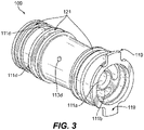
Fig. 3 is a perspective view of the embodiment of the porting manifold shown inFig. 1 ; -
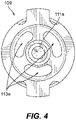
Fig. 4 is a plan view of the embodiment ofFig. 3 ; -
Fig. 5 is a cross-sectional view of the embodiment ofFig. 1 , showing flow lines of control pressure and lubrication flow through the porting manifold ofFigs. 3 and4 ; -
Fig. 6 is a partial cross-sectional view of the embodiment ofFig. 5 , showing a housing attached to the shaft for fluidly isolating the control pressure flow path from the lubrication flow path; -
Fig. 7 is a partial cross-sectional view of an embodiment in accordance with this invention, shown in a retracted position where sufficient control pressure is not applied to the hydraulic cavity to overcome the bias of the spring; -
Fig. 8 is a partial cross-sectional view of an embodiment in accordance with this invention, shown in an engaged state where sufficient control pressure is applied to the hydraulic cavity to overcome the bias of the spring and to compress the clutch pack; and -
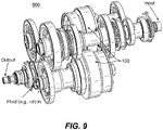
Fig. 9 is a perspective view of an embodiment of a transmission having an embodiment of a clutch assembly in accordance with this invention. - Reference will now be made to the drawings wherein like reference numerals identify similar structural features or aspects of the invention. For purposes of explanation and illustration, and not limitation, an illustrative view of an embodiment of a hydraulic clutch assembly in accordance with the invention is shown in
Fig. 1 and is designated generally byreference character 100. Other embodiments and/or aspects of this invention are shown inFigs. 2-9 . - Referring to
Figs. 1-9 generally, ahydraulic clutch assembly 100 includes ashaft 101 defining ashaft channel 103, one or morehydraulic ports 105 defined through theshaft 101, and one ormore lubrication holes 107 defined through theshaft 101. Any other suitable holes and/or construction is contemplated herein. - As shown in
Fig. 1 , aporting manifold 109 is disposed at least partially within theshaft channel 103. Theporting manifold 109 includes acontrol pressure path 111 in fluid communication with the one or morehydraulic ports 105 and alubrication flow path 113 in fluid communication with the one ormore lubrication holes 107. As shown, thecontrol pressure path 111 and thelubrication path 113 are fluidly isolated in theporting manifold 109. -
Fig. 2 shows another embodiment of aporting manifold 209 that is similar tomanifold 109, except that thelubrication flow path 213 does not pas all the way through the manifold 213 (e.g., such an embodiment can be fed lubrication oil from the shaft, left of the manifold as shown). Any other suitable paths and/or arrangement thereof are contemplated herein. - Referring additionally to
Figs. 3 and4 , thecontrol pressure path 111 can include a centralaxial channel 111a defined partially along an axial length of theporting manifold control pressure inlet 111b of theporting manifold control pressure path 111 can include one or moreradial channels 111c defined radially from the centralaxial channel 111a to a respectivecontrol pressure outlet 111d of theporting manifold shaft 101 can include acontrol pressure annulus 115 in fluid communication with the one or morecontrol pressure outlets 111d of the one or moreradial channels 111c. The one or morehydraulic ports 105 can be in fluid communication with thecontrol pressure annulus 115. - The
lubrication flow path axial lubrication channels manifold lubrication flow inlet manifold lubrication flow path radial lubrication channels axial lubrication channel lubrication flow outlet manifold shaft 101 can include alubrication flow annulus 117 in fluid communication with the one or morelubrication flow outlets radial channels 213c. One ormore lubrication holes 107 of the one or more lubrication holes can be in fluid communication with thelubrication flow annulus 117. - The porting
manifold more drive tabs 119 configured to limit insertion into theshaft 101, for example, and/or to connect the manifold 109, 209 to theshaft 101. The portingmanifold seal grooves 121. Referring additionally toFigs. 5 and 6 , theassembly 100 can include a plurality ofmanifold seals 123 disposed within theseal grooves 121 and configured to fluidly isolate the control pressure from the lubrication flow within theshaft 101. Theassembly 100 can include any other suitable seals to isolate lubrication flow and control pressure (e.g., as shown inFig. 5 ). - According to the invention the
assembly 100 includes abackstop 125 and apiston 127 disposed on theshaft 101. Thebackstop 125 is fixed to theshaft 101 and thepiston 127 is slidably engaged to theshaft 101 to move relative to theshaft 101 and thebackstop 125. Thebackstop 125 and thepiston 127 define ahydraulic cavity 129 therebetween in fluid communication with the one or morehydraulic ports 105 of theshaft 101. - As shown in
Fig. 6 , theassembly 100 can include ahousing 135 configured to provide separate connections for thecontrol pressure path 111 and thelubrication flow path 113. Any other suitable components are contemplated herein (e.g., astem 137 as shown for connecting to the housing 135). - Referring to
Figs. 2 ,7, and 8 , thepiston 127 is configured to move between a retracted position (e.g., as shown inFig. 7 ) and an engaged position (e.g., as shown inFig. 8 ) wherein thepiston 127 engages aclutch pack 131. As shown, thepiston 127 is slidably sealed to an outer diameter of the backstop 125 (e.g., via sliding seal 133). - According to the invention the
assembly 100 includes abalance dam 139 fixed to thepiston 127 and disposed around a portion of thebackstop 125 to define alubrication cavity 141 between a back side of thebackstop 125 and thebalance dam 139. Aspring 143 can be disposed between the back side of thebackstop 125 and thebalance dam 139 to bias thepiston 127 to the retracted position. Thespring 143 can be any suitable biasing member (e.g., a coil spring, a wavy washer spring). Thespring 143 can push on thebackstop 125 and thepressure dam 139 with any suitable force configured to be overcome by a suitable control pressure in thehydraulic cavity 129. - At least one
lubrication hole 107 of the one ormore lubrication holes 107 can be defined through theshaft 101 and through thebackstop 125 to fluidly communicate with thelubrication cavity 141. The lubrication flow can be ported to thecavity 141 because control pressure can be intermittent and lubrication flow can be constant to prevent movement of thepiston 127 toward the engaged position. Any other suitable lubrication holes are contemplated herein. - The
assembly 100 can include an innerclutch basket 145 rotationally fixed to theshaft 101 to turn with theshaft 101. Theassembly 100 can include an outerclutch basket 147 rotatably mounted on theshaft 101 to rotate relative to theshaft 101. Theassembly 100 can include aclutch pack 131 disposed between the innerclutch basket 145 and the outerclutch basket 147. Theclutch pack 131 can be configured to be compressed by thepiston 131 in the engaged position (e.g., as shown inFig. 8 ) to engage the innerclutch basket 145 to the outerclutch basket 147 to cause the outerclutch basket 147 to rotate with the innerclutch basket 145 and theshaft 100. - The
clutch pack 131 can include a plurality ofseparator discs 149 slidably connected to the innerclutch basket 145 and a plurality offriction discs 151 connected to the outerclutch basket 147. Theseparator discs 149 can be pressed by thepiston 127 to slide and contact thefriction discs 151 to engage theseparator discus 149 to thefriction discs 151. It is contemplated that thefriction discs 151 can be connected to the outerclutch basket 147 and theseparator discs 149 can be connected to the innerclutch basket 145. Any other suitable arrangement and/or clutch pack type is contemplated herein. - The control pressure fluid and/or the lubrication fluid can be an oil, for example. Any other suitable fluid (e.g., hydraulic fluid) is contemplated herein.
- Referring additionally to
Fig. 9 , any suitable embodiment of an assembly, e.g., 100 can be utilized in atransmission 900. For example,transmission 900 can be attached to a low spool of a turbomachine engine. Thetransmission 900 can include any suitable number of stages (e.g., 4 stages as shown). - In accordance with at least one aspect of this invention, a method includes providing a hydraulic control pressure through a shaft of a transmission to control a position of a piston of a clutch assembly to selectively engage a clutch pack of the clutch assembly. The method includes providing a lubrication flow fluidly isolated from the control pressure through the shaft. The method can include any other suitable method and/or portion thereof.
- In certain embodiments, when control pressure is low (e.g., less than the lubrication flow pressure), the clutch can be open and the outer clutch basket and inner clutch basket can rotate at different speeds. In certain embodiments, when control pressure is high (e.g., above lubrication flow pressure), the clutch can be closed and the outer clutch basket and inner clutch basket rotate at the same speed. Torque is then transmitted between the inner and outer clutch baskets.
- Embodiments can utilize a clutch/piston arrangement in a low spool transmission on a jet engine accessory drive. Embodiments use hydraulic power to clamp and unclamp a clutch pack which selectively transmits torque between the inner and outer clutch bell. In certain embodiments, a piston return spring and a centrifugal pressure balance disc/dam ensures predictable operation across a wide operating speed band.
- Embodiments include a suitable rotating clutch seal arrangement. Because control pressure and lubrication flow must be directed to the appropriate locations for proper operation, seals can be used to isolate the flow paths needed for proper clutch operation and to prevent unwanted leakage. As disclosed above, embodiments of a seal arrangement isolate two paths of flow/pressure. Embodiments allow for the movement of the clutch piston while sealing.
- Those having ordinary skill in the art understand that any numerical values disclosed herein can be exact values or can be values within a range. Further, any terms of approximation (e.g., "about", "approximately", "around") used in this invention can mean the stated value within a range. For example, in certain embodiments, the range can be within (plus or minus) 20%, or within 10%, or within 5%, or within 2%, or within any other suitable percentage or number as appreciated by those having ordinary skill in the art (e.g., for known tolerance limits or error ranges).
- Any suitable combination(s) of any disclosed embodiments and/or any suitable portion(s) thereof are contemplated herein as appreciated by those having ordinary skill in the art.
- The embodiments of the present invention, as described above and shown in the drawings, provide for improvement in the art to which they pertain.
Claims (8)
- A hydraulic clutch assembly, comprising:a shaft (101) defining a shaft channel (103), one or more hydraulic ports (105) defined through the shaft, and one or more lubrication holes (107) defined through the shaft; anda porting manifold (209) disposed at least partially within the shaft channel, wherein the porting manifold includes a control pressure path in fluid communication with the one or more hydraulic ports and a lubrication flow path in fluid communication with the one or more lubrication holes, wherein the control pressure path and the lubrication path are fluidly isolated in the porting manifold;a backstop (125) and a piston (127) disposed on the shaft, wherein the backstop is fixed to the shaft, wherein the piston is slidably engaged to the shaft to move relative to the shaft and the backstop, wherein the backstop and the piston define a hydraulic cavity (129) therebetween in fluid communication with the one or more hydraulic ports of the shaft, wherein the piston is configured to move between a retracted position and an engaged position wherein the piston engages a clutch pack, wherein the piston is slidably sealed to an outer diameter of the backstop; and characterized by:a balance dam (139) fixed to the piston and disposed around a portion of the backstop to define a lubrication cavity between a back side of the backstop and the balance dam.
- The assembly of claim 1, wherein the control pressure path includes:a central axial channel (111a) defined partially along an axial length of the porting manifold from a control pressure inlet of the porting manifold; andone or more radial channels (111c) defined radially from the central axial channel to a respective control pressure outlet of the porting manifold, andwherein the control pressure path includes a control pressure annulus in fluid communication with the one or more control pressure outlets of the one or more radial channels, wherein the one or more hydraulic ports are in fluid communication with the control pressure annulus.
- The assembly of claims 1 or 2, wherein the lubrication flow path includes:one or more axial lubrication channels defined at least partially along an axial length of the porting manifold from a lubrication flow inlet of the porting manifold; andone or more radial lubrication channels defined radially from a respective axial lubrication channel to a respective lubrication flow outlet of the porting manifold, and preferablywherein the shaft includes a lubrication flow annulus in fluid communication with the one or more lubrication flow outlets of the one or more radial channels, wherein, one or more lubrication holes of the one or more lubrication holes are in fluid communication with the lubrication flow annulus.
- The assembly of any preceding claim, wherein the porting manifold includes one or more drive tabs (119) configured to limit insertion into the shaft.
- The assembly of any preceding claim, wherein the porting manifold includes a plurality of seal grooves (121), wherein the assembly further comprising a plurality of manifold seals (123) disposed within the seal grooves and configured to fluidly isolate the control pressure from the lubrication flow within the shaft.
- The assembly of claim 1, further comprising a spring (143) disposed between the back side of the backstop and the balance dam to bias the piston to the retracted position, and
wherein at least one lubrication hole of the one or more lubrication holes is defined through the shaft and through the backstop to fluidly communicate with the lubrication cavity. - The assembly of claim 1, further comprising an inner clutch basket (145) rotationally fixed to the shaft to turn with the shaft, an outer clutch basket (147) rotatably mounted on the shaft to rotate relative to the shaft, and a clutch pack disposed between the inner clutch basket and the outer clutch basket configured to be compressed by the piston in the engaged position to engage the inner clutch basket to the outer clutch basket to cause the outer clutch basket to rotate with the inner clutch basket and the shaft.
- A method for controlling a hydraulic clutch assembly according to any of claims 1-7, comprising:
providing a hydraulic control pressure through a shaft of a transmission to control a position of a piston of a clutch assembly to selectively engage a clutch pack of the clutch assembly, wherein providing hydraulic control pressure includes providing control pressure through one or more hydraulic ports of the shaft to a hydraulic cavity defined between a backstop and a piston, and providing a lubrication flow fluidly isolated from the control pressure through the shaft to a lubrication cavity between a back side of the backstop and a balance dam.
Priority Applications (1)
| Application Number | Priority Date | Filing Date | Title |
|---|---|---|---|
| EP22211254.2A EP4166806B1 (en) | 2019-04-18 | 2019-11-28 | A porting manifold |
Applications Claiming Priority (1)
| Application Number | Priority Date | Filing Date | Title |
|---|---|---|---|
| US16/388,254 US11226014B2 (en) | 2019-04-18 | 2019-04-18 | Hydraulic clutch assemblies |
Related Child Applications (1)
| Application Number | Title | Priority Date | Filing Date |
|---|---|---|---|
| EP22211254.2A Division EP4166806B1 (en) | 2019-04-18 | 2019-11-28 | A porting manifold |
Publications (2)
| Publication Number | Publication Date |
|---|---|
| EP3726086A1 EP3726086A1 (en) | 2020-10-21 |
| EP3726086B1 true EP3726086B1 (en) | 2022-12-28 |
Family
ID=68731816
Family Applications (2)
| Application Number | Title | Priority Date | Filing Date |
|---|---|---|---|
| EP19212094.7A Active EP3726086B1 (en) | 2019-04-18 | 2019-11-28 | Hydraulic clutch assemblies |
| EP22211254.2A Active EP4166806B1 (en) | 2019-04-18 | 2019-11-28 | A porting manifold |
Family Applications After (1)
| Application Number | Title | Priority Date | Filing Date |
|---|---|---|---|
| EP22211254.2A Active EP4166806B1 (en) | 2019-04-18 | 2019-11-28 | A porting manifold |
Country Status (2)
| Country | Link |
|---|---|
| US (1) | US11226014B2 (en) |
| EP (2) | EP3726086B1 (en) |
Families Citing this family (4)
| Publication number | Priority date | Publication date | Assignee | Title |
|---|---|---|---|---|
| DE102021207114A1 (en) | 2021-07-07 | 2023-01-12 | Zf Friedrichshafen Ag | Multi-piece shaft assembly |
| FR3137949B1 (en) * | 2022-07-13 | 2024-08-16 | Safran Aircraft Engines | Gear change system for aircraft turbomachine accessory relay box and method of use |
| US12000343B1 (en) | 2023-04-04 | 2024-06-04 | Hamilton Sundstrand Corporation | Pressure balancing of rotating control piston of generator transmission |
| US12188551B1 (en) * | 2023-09-29 | 2025-01-07 | Rtx Corporation | Reduced clearance interface between a fluid device and a rotating structure for a geartrain |
Family Cites Families (13)
| Publication number | Priority date | Publication date | Assignee | Title |
|---|---|---|---|---|
| DE1052315B (en) | 1952-07-29 | 1959-03-05 | Clark Equipment Co | Gearbox with hydraulic control device for driving lifting vehicles |
| US3823802A (en) * | 1972-08-18 | 1974-07-16 | Caterpillar Tractor Co | Clutch with controlled coolant flow |
| US3863746A (en) * | 1973-03-30 | 1975-02-04 | Caterpillar Tractor Co | Centrifugally balanced rotating clutch |
| JP4082926B2 (en) | 2002-05-07 | 2008-04-30 | 本田技研工業株式会社 | Automatic transmission |
| US6840363B2 (en) | 2003-02-06 | 2005-01-11 | Borgwarner, Inc. | Multi-disk friction device selective lubrication on demand |
| DE102009006647B4 (en) | 2008-02-04 | 2019-01-31 | Schaeffler Technologies AG & Co. KG | Dual clutch assembly |
| US8439083B2 (en) * | 2008-11-05 | 2013-05-14 | Allison Transmission, Inc. | Apparatus and method for axially transferring fluids to a plurality of components |
| US8647078B2 (en) | 2011-02-24 | 2014-02-11 | Ford Global Technologies, Llc | Motor pump assembly for transmission valve body |
| JP2012192913A (en) | 2011-02-28 | 2012-10-11 | Aisin Aw Co Ltd | Driving device for vehicle |
| CN103380315B (en) | 2011-03-31 | 2016-06-01 | 爱信艾达株式会社 | Apparatus for starting |
| KR101437152B1 (en) | 2011-11-07 | 2014-09-11 | 씨스톤 테크놀로지스(주) | Clutch |
| WO2014149121A2 (en) | 2013-03-07 | 2014-09-25 | Bouton Matthew T | Clutch coupled to gas turbine engine and method for cooling |
| CN107269743A (en) | 2017-07-27 | 2017-10-20 | 雷沃重工股份有限公司 | A kind of wet type engaging power output device and tractor |
-
2019
- 2019-04-18 US US16/388,254 patent/US11226014B2/en active Active
- 2019-11-28 EP EP19212094.7A patent/EP3726086B1/en active Active
- 2019-11-28 EP EP22211254.2A patent/EP4166806B1/en active Active
Also Published As
| Publication number | Publication date |
|---|---|
| US20200332882A1 (en) | 2020-10-22 |
| US11226014B2 (en) | 2022-01-18 |
| EP4166806B1 (en) | 2025-06-25 |
| EP4166806A1 (en) | 2023-04-19 |
| EP3726086A1 (en) | 2020-10-21 |
Similar Documents
| Publication | Publication Date | Title |
|---|---|---|
| EP3726086B1 (en) | Hydraulic clutch assemblies | |
| US9709146B2 (en) | Lock-up device for torque converter | |
| EP0282169B1 (en) | Clutch assembly with a pressure-balance chamber | |
| US4467669A (en) | Working fluid distributing system for a belt drive continuously-variable speed automatic transmission | |
| EP1043512B1 (en) | Rotating clutch balance apparatus | |
| US10895311B2 (en) | Four-pass torque converter with variable-pitch stator and bypass clutch | |
| EP1918602B1 (en) | Clutch assembly with bleed assembly for centrifugal pressure | |
| US7140481B2 (en) | Clutch piston amplifier assembly | |
| KR102487179B1 (en) | Clutch device for automatic transmission | |
| US8424661B2 (en) | Power transmitting apparatus | |
| EP3726083B1 (en) | Wet clutch assemblies | |
| CN114051565A (en) | Torque Converter Clutch System | |
| US8764597B2 (en) | Concentric V-groove coupling | |
| US9382998B1 (en) | Interplanetary clutch actuator | |
| KR102487178B1 (en) | Two-stage clutch device for automatic transmission | |
| US7481305B2 (en) | Lock-up mechanism for torque converter | |
| KR20190068974A (en) | Clutch device for automatic transmission | |
| US10844940B2 (en) | Torque converter with charge pressure compensation | |
| KR102589912B1 (en) | Clutch device for automatic transmission | |
| KR102487176B1 (en) | Clutch device for automatic transmission | |
| US3326065A (en) | Hydrokinetic and mechanical gear drive | |
| WO2017082879A1 (en) | Torque converter having controllable dual clutches | |
| US12000343B1 (en) | Pressure balancing of rotating control piston of generator transmission | |
| US4924982A (en) | Oil pressure clutch mechanism for an automatic transmission | |
| US11306804B1 (en) | Torque converter with cross-flow pressure chambers |
Legal Events
| Date | Code | Title | Description |
|---|---|---|---|
| PUAI | Public reference made under article 153(3) epc to a published international application that has entered the european phase |
Free format text: ORIGINAL CODE: 0009012 |
|
| STAA | Information on the status of an ep patent application or granted ep patent |
Free format text: STATUS: THE APPLICATION HAS BEEN PUBLISHED |
|
| AK | Designated contracting states |
Kind code of ref document: A1 Designated state(s): AL AT BE BG CH CY CZ DE DK EE ES FI FR GB GR HR HU IE IS IT LI LT LU LV MC MK MT NL NO PL PT RO RS SE SI SK SM TR |
|
| AX | Request for extension of the european patent |
Extension state: BA ME |
|
| STAA | Information on the status of an ep patent application or granted ep patent |
Free format text: STATUS: REQUEST FOR EXAMINATION WAS MADE |
|
| 17P | Request for examination filed |
Effective date: 20210421 |
|
| RBV | Designated contracting states (corrected) |
Designated state(s): AL AT BE BG CH CY CZ DE DK EE ES FI FR GB GR HR HU IE IS IT LI LT LU LV MC MK MT NL NO PL PT RO RS SE SI SK SM TR |
|
| GRAP | Despatch of communication of intention to grant a patent |
Free format text: ORIGINAL CODE: EPIDOSNIGR1 |
|
| STAA | Information on the status of an ep patent application or granted ep patent |
Free format text: STATUS: GRANT OF PATENT IS INTENDED |
|
| INTG | Intention to grant announced |
Effective date: 20220715 |
|
| GRAS | Grant fee paid |
Free format text: ORIGINAL CODE: EPIDOSNIGR3 |
|
| GRAA | (expected) grant |
Free format text: ORIGINAL CODE: 0009210 |
|
| STAA | Information on the status of an ep patent application or granted ep patent |
Free format text: STATUS: THE PATENT HAS BEEN GRANTED |
|
| AK | Designated contracting states |
Kind code of ref document: B1 Designated state(s): AL AT BE BG CH CY CZ DE DK EE ES FI FR GB GR HR HU IE IS IT LI LT LU LV MC MK MT NL NO PL PT RO RS SE SI SK SM TR |
|
| REG | Reference to a national code |
Ref country code: GB Ref legal event code: FG4D |
|
| REG | Reference to a national code |
Ref country code: CH Ref legal event code: EP |
|
| REG | Reference to a national code |
Ref country code: DE Ref legal event code: R096 Ref document number: 602019023644 Country of ref document: DE |
|
| REG | Reference to a national code |
Ref country code: AT Ref legal event code: REF Ref document number: 1540676 Country of ref document: AT Kind code of ref document: T Effective date: 20230115 |
|
| REG | Reference to a national code |
Ref country code: IE Ref legal event code: FG4D |
|
| REG | Reference to a national code |
Ref country code: LT Ref legal event code: MG9D |
|
| PG25 | Lapsed in a contracting state [announced via postgrant information from national office to epo] |
Ref country code: SE Free format text: LAPSE BECAUSE OF FAILURE TO SUBMIT A TRANSLATION OF THE DESCRIPTION OR TO PAY THE FEE WITHIN THE PRESCRIBED TIME-LIMIT Effective date: 20221228 Ref country code: NO Free format text: LAPSE BECAUSE OF FAILURE TO SUBMIT A TRANSLATION OF THE DESCRIPTION OR TO PAY THE FEE WITHIN THE PRESCRIBED TIME-LIMIT Effective date: 20230328 Ref country code: LT Free format text: LAPSE BECAUSE OF FAILURE TO SUBMIT A TRANSLATION OF THE DESCRIPTION OR TO PAY THE FEE WITHIN THE PRESCRIBED TIME-LIMIT Effective date: 20221228 Ref country code: FI Free format text: LAPSE BECAUSE OF FAILURE TO SUBMIT A TRANSLATION OF THE DESCRIPTION OR TO PAY THE FEE WITHIN THE PRESCRIBED TIME-LIMIT Effective date: 20221228 |
|
| REG | Reference to a national code |
Ref country code: NL Ref legal event code: MP Effective date: 20221228 |
|
| REG | Reference to a national code |
Ref country code: AT Ref legal event code: MK05 Ref document number: 1540676 Country of ref document: AT Kind code of ref document: T Effective date: 20221228 |
|
| PG25 | Lapsed in a contracting state [announced via postgrant information from national office to epo] |
Ref country code: RS Free format text: LAPSE BECAUSE OF FAILURE TO SUBMIT A TRANSLATION OF THE DESCRIPTION OR TO PAY THE FEE WITHIN THE PRESCRIBED TIME-LIMIT Effective date: 20221228 Ref country code: LV Free format text: LAPSE BECAUSE OF FAILURE TO SUBMIT A TRANSLATION OF THE DESCRIPTION OR TO PAY THE FEE WITHIN THE PRESCRIBED TIME-LIMIT Effective date: 20221228 Ref country code: HR Free format text: LAPSE BECAUSE OF FAILURE TO SUBMIT A TRANSLATION OF THE DESCRIPTION OR TO PAY THE FEE WITHIN THE PRESCRIBED TIME-LIMIT Effective date: 20221228 Ref country code: GR Free format text: LAPSE BECAUSE OF FAILURE TO SUBMIT A TRANSLATION OF THE DESCRIPTION OR TO PAY THE FEE WITHIN THE PRESCRIBED TIME-LIMIT Effective date: 20230329 |
|
| PG25 | Lapsed in a contracting state [announced via postgrant information from national office to epo] |
Ref country code: NL Free format text: LAPSE BECAUSE OF FAILURE TO SUBMIT A TRANSLATION OF THE DESCRIPTION OR TO PAY THE FEE WITHIN THE PRESCRIBED TIME-LIMIT Effective date: 20221228 |
|
| P01 | Opt-out of the competence of the unified patent court (upc) registered |
Effective date: 20230603 |
|
| PG25 | Lapsed in a contracting state [announced via postgrant information from national office to epo] |
Ref country code: SM Free format text: LAPSE BECAUSE OF FAILURE TO SUBMIT A TRANSLATION OF THE DESCRIPTION OR TO PAY THE FEE WITHIN THE PRESCRIBED TIME-LIMIT Effective date: 20221228 Ref country code: RO Free format text: LAPSE BECAUSE OF FAILURE TO SUBMIT A TRANSLATION OF THE DESCRIPTION OR TO PAY THE FEE WITHIN THE PRESCRIBED TIME-LIMIT Effective date: 20221228 Ref country code: PT Free format text: LAPSE BECAUSE OF FAILURE TO SUBMIT A TRANSLATION OF THE DESCRIPTION OR TO PAY THE FEE WITHIN THE PRESCRIBED TIME-LIMIT Effective date: 20230428 Ref country code: ES Free format text: LAPSE BECAUSE OF FAILURE TO SUBMIT A TRANSLATION OF THE DESCRIPTION OR TO PAY THE FEE WITHIN THE PRESCRIBED TIME-LIMIT Effective date: 20221228 Ref country code: EE Free format text: LAPSE BECAUSE OF FAILURE TO SUBMIT A TRANSLATION OF THE DESCRIPTION OR TO PAY THE FEE WITHIN THE PRESCRIBED TIME-LIMIT Effective date: 20221228 Ref country code: CZ Free format text: LAPSE BECAUSE OF FAILURE TO SUBMIT A TRANSLATION OF THE DESCRIPTION OR TO PAY THE FEE WITHIN THE PRESCRIBED TIME-LIMIT Effective date: 20221228 Ref country code: AT Free format text: LAPSE BECAUSE OF FAILURE TO SUBMIT A TRANSLATION OF THE DESCRIPTION OR TO PAY THE FEE WITHIN THE PRESCRIBED TIME-LIMIT Effective date: 20221228 |
|
| PG25 | Lapsed in a contracting state [announced via postgrant information from national office to epo] |
Ref country code: SK Free format text: LAPSE BECAUSE OF FAILURE TO SUBMIT A TRANSLATION OF THE DESCRIPTION OR TO PAY THE FEE WITHIN THE PRESCRIBED TIME-LIMIT Effective date: 20221228 Ref country code: PL Free format text: LAPSE BECAUSE OF FAILURE TO SUBMIT A TRANSLATION OF THE DESCRIPTION OR TO PAY THE FEE WITHIN THE PRESCRIBED TIME-LIMIT Effective date: 20221228 Ref country code: IS Free format text: LAPSE BECAUSE OF FAILURE TO SUBMIT A TRANSLATION OF THE DESCRIPTION OR TO PAY THE FEE WITHIN THE PRESCRIBED TIME-LIMIT Effective date: 20230428 Ref country code: AL Free format text: LAPSE BECAUSE OF FAILURE TO SUBMIT A TRANSLATION OF THE DESCRIPTION OR TO PAY THE FEE WITHIN THE PRESCRIBED TIME-LIMIT Effective date: 20221228 |
|
| REG | Reference to a national code |
Ref country code: DE Ref legal event code: R097 Ref document number: 602019023644 Country of ref document: DE |
|
| PG25 | Lapsed in a contracting state [announced via postgrant information from national office to epo] |
Ref country code: DK Free format text: LAPSE BECAUSE OF FAILURE TO SUBMIT A TRANSLATION OF THE DESCRIPTION OR TO PAY THE FEE WITHIN THE PRESCRIBED TIME-LIMIT Effective date: 20221228 |
|
| PLBE | No opposition filed within time limit |
Free format text: ORIGINAL CODE: 0009261 |
|
| STAA | Information on the status of an ep patent application or granted ep patent |
Free format text: STATUS: NO OPPOSITION FILED WITHIN TIME LIMIT |
|
| 26N | No opposition filed |
Effective date: 20230929 |
|
| PG25 | Lapsed in a contracting state [announced via postgrant information from national office to epo] |
Ref country code: SI Free format text: LAPSE BECAUSE OF FAILURE TO SUBMIT A TRANSLATION OF THE DESCRIPTION OR TO PAY THE FEE WITHIN THE PRESCRIBED TIME-LIMIT Effective date: 20221228 |
|
| PG25 | Lapsed in a contracting state [announced via postgrant information from national office to epo] |
Ref country code: IT Free format text: LAPSE BECAUSE OF FAILURE TO SUBMIT A TRANSLATION OF THE DESCRIPTION OR TO PAY THE FEE WITHIN THE PRESCRIBED TIME-LIMIT Effective date: 20221228 |
|
| REG | Reference to a national code |
Ref country code: CH Ref legal event code: PL |
|
| PG25 | Lapsed in a contracting state [announced via postgrant information from national office to epo] |
Ref country code: MC Free format text: LAPSE BECAUSE OF FAILURE TO SUBMIT A TRANSLATION OF THE DESCRIPTION OR TO PAY THE FEE WITHIN THE PRESCRIBED TIME-LIMIT Effective date: 20221228 |
|
| PG25 | Lapsed in a contracting state [announced via postgrant information from national office to epo] |
Ref country code: LU Free format text: LAPSE BECAUSE OF NON-PAYMENT OF DUE FEES Effective date: 20231128 |
|
| PG25 | Lapsed in a contracting state [announced via postgrant information from national office to epo] |
Ref country code: CH Free format text: LAPSE BECAUSE OF NON-PAYMENT OF DUE FEES Effective date: 20231130 |
|
| PG25 | Lapsed in a contracting state [announced via postgrant information from national office to epo] |
Ref country code: MC Free format text: LAPSE BECAUSE OF FAILURE TO SUBMIT A TRANSLATION OF THE DESCRIPTION OR TO PAY THE FEE WITHIN THE PRESCRIBED TIME-LIMIT Effective date: 20221228 Ref country code: LU Free format text: LAPSE BECAUSE OF NON-PAYMENT OF DUE FEES Effective date: 20231128 Ref country code: CH Free format text: LAPSE BECAUSE OF NON-PAYMENT OF DUE FEES Effective date: 20231130 |
|
| REG | Reference to a national code |
Ref country code: BE Ref legal event code: MM Effective date: 20231130 |
|
| REG | Reference to a national code |
Ref country code: IE Ref legal event code: MM4A |
|
| PG25 | Lapsed in a contracting state [announced via postgrant information from national office to epo] |
Ref country code: IE Free format text: LAPSE BECAUSE OF NON-PAYMENT OF DUE FEES Effective date: 20231128 |
|
| PG25 | Lapsed in a contracting state [announced via postgrant information from national office to epo] |
Ref country code: BE Free format text: LAPSE BECAUSE OF NON-PAYMENT OF DUE FEES Effective date: 20231130 |
|
| PG25 | Lapsed in a contracting state [announced via postgrant information from national office to epo] |
Ref country code: IE Free format text: LAPSE BECAUSE OF NON-PAYMENT OF DUE FEES Effective date: 20231128 Ref country code: BE Free format text: LAPSE BECAUSE OF NON-PAYMENT OF DUE FEES Effective date: 20231130 |
|
| PG25 | Lapsed in a contracting state [announced via postgrant information from national office to epo] |
Ref country code: BG Free format text: LAPSE BECAUSE OF FAILURE TO SUBMIT A TRANSLATION OF THE DESCRIPTION OR TO PAY THE FEE WITHIN THE PRESCRIBED TIME-LIMIT Effective date: 20221228 |
|
| PG25 | Lapsed in a contracting state [announced via postgrant information from national office to epo] |
Ref country code: BG Free format text: LAPSE BECAUSE OF FAILURE TO SUBMIT A TRANSLATION OF THE DESCRIPTION OR TO PAY THE FEE WITHIN THE PRESCRIBED TIME-LIMIT Effective date: 20221228 |
|
| PG25 | Lapsed in a contracting state [announced via postgrant information from national office to epo] |
Ref country code: CY Free format text: LAPSE BECAUSE OF FAILURE TO SUBMIT A TRANSLATION OF THE DESCRIPTION OR TO PAY THE FEE WITHIN THE PRESCRIBED TIME-LIMIT; INVALID AB INITIO Effective date: 20191128 |
|
| PG25 | Lapsed in a contracting state [announced via postgrant information from national office to epo] |
Ref country code: HU Free format text: LAPSE BECAUSE OF FAILURE TO SUBMIT A TRANSLATION OF THE DESCRIPTION OR TO PAY THE FEE WITHIN THE PRESCRIBED TIME-LIMIT; INVALID AB INITIO Effective date: 20191128 |
|
| PG25 | Lapsed in a contracting state [announced via postgrant information from national office to epo] |
Ref country code: TR Free format text: LAPSE BECAUSE OF FAILURE TO SUBMIT A TRANSLATION OF THE DESCRIPTION OR TO PAY THE FEE WITHIN THE PRESCRIBED TIME-LIMIT Effective date: 20221228 |
|
| PGFP | Annual fee paid to national office [announced via postgrant information from national office to epo] |
Ref country code: DE Payment date: 20251022 Year of fee payment: 7 |
|
| PGFP | Annual fee paid to national office [announced via postgrant information from national office to epo] |
Ref country code: GB Payment date: 20251023 Year of fee payment: 7 |
|
| PGFP | Annual fee paid to national office [announced via postgrant information from national office to epo] |
Ref country code: FR Payment date: 20251022 Year of fee payment: 7 |