EP3726063B1 - Fluid-cooled electrically driven compressor and stator housing therefor - Google Patents
Fluid-cooled electrically driven compressor and stator housing therefor Download PDFInfo
- Publication number
- EP3726063B1 EP3726063B1 EP19169231.8A EP19169231A EP3726063B1 EP 3726063 B1 EP3726063 B1 EP 3726063B1 EP 19169231 A EP19169231 A EP 19169231A EP 3726063 B1 EP3726063 B1 EP 3726063B1
- Authority
- EP
- European Patent Office
- Prior art keywords
- fluid flow
- wall
- longitudinal axis
- stator housing
- stator
- Prior art date
- Legal status (The legal status is an assumption and is not a legal conclusion. Google has not performed a legal analysis and makes no representation as to the accuracy of the status listed.)
- Active
Links
- 239000012530 fluid Substances 0.000 claims description 136
- 239000012809 cooling fluid Substances 0.000 claims description 35
- 238000002485 combustion reaction Methods 0.000 claims description 6
- 239000013598 vector Substances 0.000 description 10
- 238000001816 cooling Methods 0.000 description 9
- 239000003570 air Substances 0.000 description 6
- 230000003247 decreasing effect Effects 0.000 description 4
- 239000012080 ambient air Substances 0.000 description 2
- 238000005266 casting Methods 0.000 description 2
- 230000007423 decrease Effects 0.000 description 2
- 239000000446 fuel Substances 0.000 description 2
- 239000000411 inducer Substances 0.000 description 2
- 238000004519 manufacturing process Methods 0.000 description 2
- 238000007789 sealing Methods 0.000 description 2
- 230000004323 axial length Effects 0.000 description 1
- 238000004512 die casting Methods 0.000 description 1
- 238000009826 distribution Methods 0.000 description 1
- 230000000694 effects Effects 0.000 description 1
- 239000002184 metal Substances 0.000 description 1
- 238000000034 method Methods 0.000 description 1
- 238000012986 modification Methods 0.000 description 1
- 230000004048 modification Effects 0.000 description 1
- 238000004088 simulation Methods 0.000 description 1
- 230000006641 stabilisation Effects 0.000 description 1
- 238000011105 stabilization Methods 0.000 description 1
- 230000003685 thermal hair damage Effects 0.000 description 1
- 230000007704 transition Effects 0.000 description 1
- 238000011144 upstream manufacturing Methods 0.000 description 1
- XLYOFNOQVPJJNP-UHFFFAOYSA-N water Substances O XLYOFNOQVPJJNP-UHFFFAOYSA-N 0.000 description 1
- 238000004804 winding Methods 0.000 description 1
Images


Classifications
-
- F—MECHANICAL ENGINEERING; LIGHTING; HEATING; WEAPONS; BLASTING
- F04—POSITIVE - DISPLACEMENT MACHINES FOR LIQUIDS; PUMPS FOR LIQUIDS OR ELASTIC FLUIDS
- F04D—NON-POSITIVE-DISPLACEMENT PUMPS
- F04D29/00—Details, component parts, or accessories
- F04D29/58—Cooling; Heating; Diminishing heat transfer
- F04D29/5806—Cooling the drive system
-
- F—MECHANICAL ENGINEERING; LIGHTING; HEATING; WEAPONS; BLASTING
- F04—POSITIVE - DISPLACEMENT MACHINES FOR LIQUIDS; PUMPS FOR LIQUIDS OR ELASTIC FLUIDS
- F04D—NON-POSITIVE-DISPLACEMENT PUMPS
- F04D29/00—Details, component parts, or accessories
- F04D29/58—Cooling; Heating; Diminishing heat transfer
- F04D29/582—Cooling; Heating; Diminishing heat transfer specially adapted for elastic fluid pumps
- F04D29/5846—Cooling; Heating; Diminishing heat transfer specially adapted for elastic fluid pumps cooling by injection
-
- H—ELECTRICITY
- H02—GENERATION; CONVERSION OR DISTRIBUTION OF ELECTRIC POWER
- H02K—DYNAMO-ELECTRIC MACHINES
- H02K5/00—Casings; Enclosures; Supports
- H02K5/04—Casings or enclosures characterised by the shape, form or construction thereof
- H02K5/20—Casings or enclosures characterised by the shape, form or construction thereof with channels or ducts for flow of cooling medium
- H02K5/203—Casings or enclosures characterised by the shape, form or construction thereof with channels or ducts for flow of cooling medium specially adapted for liquids, e.g. cooling jackets
-
- F—MECHANICAL ENGINEERING; LIGHTING; HEATING; WEAPONS; BLASTING
- F04—POSITIVE - DISPLACEMENT MACHINES FOR LIQUIDS; PUMPS FOR LIQUIDS OR ELASTIC FLUIDS
- F04D—NON-POSITIVE-DISPLACEMENT PUMPS
- F04D17/00—Radial-flow pumps, e.g. centrifugal pumps; Helico-centrifugal pumps
- F04D17/08—Centrifugal pumps
- F04D17/10—Centrifugal pumps for compressing or evacuating
-
- F—MECHANICAL ENGINEERING; LIGHTING; HEATING; WEAPONS; BLASTING
- F04—POSITIVE - DISPLACEMENT MACHINES FOR LIQUIDS; PUMPS FOR LIQUIDS OR ELASTIC FLUIDS
- F04D—NON-POSITIVE-DISPLACEMENT PUMPS
- F04D25/00—Pumping installations or systems
- F04D25/02—Units comprising pumps and their driving means
- F04D25/06—Units comprising pumps and their driving means the pump being electrically driven
- F04D25/0606—Units comprising pumps and their driving means the pump being electrically driven the electric motor being specially adapted for integration in the pump
-
- H—ELECTRICITY
- H02—GENERATION; CONVERSION OR DISTRIBUTION OF ELECTRIC POWER
- H02K—DYNAMO-ELECTRIC MACHINES
- H02K5/00—Casings; Enclosures; Supports
- H02K5/04—Casings or enclosures characterised by the shape, form or construction thereof
- H02K5/12—Casings or enclosures characterised by the shape, form or construction thereof specially adapted for operating in liquid or gas
- H02K5/128—Casings or enclosures characterised by the shape, form or construction thereof specially adapted for operating in liquid or gas using air-gap sleeves or air-gap discs
-
- H—ELECTRICITY
- H02—GENERATION; CONVERSION OR DISTRIBUTION OF ELECTRIC POWER
- H02K—DYNAMO-ELECTRIC MACHINES
- H02K7/00—Arrangements for handling mechanical energy structurally associated with dynamo-electric machines, e.g. structural association with mechanical driving motors or auxiliary dynamo-electric machines
- H02K7/14—Structural association with mechanical loads, e.g. with hand-held machine tools or fans
-
- F—MECHANICAL ENGINEERING; LIGHTING; HEATING; WEAPONS; BLASTING
- F02—COMBUSTION ENGINES; HOT-GAS OR COMBUSTION-PRODUCT ENGINE PLANTS
- F02B—INTERNAL-COMBUSTION PISTON ENGINES; COMBUSTION ENGINES IN GENERAL
- F02B39/00—Component parts, details, or accessories relating to, driven charging or scavenging pumps, not provided for in groups F02B33/00 - F02B37/00
- F02B39/02—Drives of pumps; Varying pump drive gear ratio
- F02B39/08—Non-mechanical drives, e.g. fluid drives having variable gear ratio
- F02B39/10—Non-mechanical drives, e.g. fluid drives having variable gear ratio electric
-
- H—ELECTRICITY
- H02—GENERATION; CONVERSION OR DISTRIBUTION OF ELECTRIC POWER
- H02K—DYNAMO-ELECTRIC MACHINES
- H02K11/00—Structural association of dynamo-electric machines with electric components or with devices for shielding, monitoring or protection
- H02K11/30—Structural association with control circuits or drive circuits
- H02K11/33—Drive circuits, e.g. power electronics
-
- H—ELECTRICITY
- H02—GENERATION; CONVERSION OR DISTRIBUTION OF ELECTRIC POWER
- H02K—DYNAMO-ELECTRIC MACHINES
- H02K2213/00—Specific aspects, not otherwise provided for and not covered by codes H02K2201/00 - H02K2211/00
- H02K2213/03—Machines characterised by numerical values, ranges, mathematical expressions or similar information
Definitions
- the present disclosure relates to a compressor for an internal combustion engine. More particularly, the present disclosure relates to a stator housing for a fluid-cooled electrically driven compressor and to a fluid-cooled electrically driven compressor comprising this stator housing.
- Compressors deliver compressed air to an intake of an internal combustion engine, allowing more fuel to be combusted. As a result, a power density of the engine is increased without significantly increasing engine weight. Compressors thus permit the use of smaller engines that develop the same amount of power as larger, normally aspirated engines. Using a smaller engine in a vehicle has the desired effect of decreasing the vehicle mass, increasing performance and reducing fuel consumption. Moreover, the use of compressors leads to an improved combustion and, therefore, to reduced emissions.
- Exhaust gas turbochargers include a turbine housing having an inlet passage connected to an exhaust manifold of the engine, a compressor housing having an outlet passage connected to an intake manifold of the engine, and a bearing housing interconnecting the turbine housing and the compressor housing.
- An exhaust gas flow from the exhaust manifold rotatably drives a turbine wheel in the turbine housing.
- the turbine wheel is connected via a rotor shaft rotatably supported in the bearing housing to a compressor wheel in the compressor housing. Rotation of the turbine wheel by the exhaust gas flow thus causes rotation of the compressor wheel.
- the rotating compressor wheel draws ambient air via a so-called inducer into the compressor housing and compresses the air. Downstream of the compressor wheel the compressed air enters a diffusor channel from which the compressed air is guided via a compressor cover to the intake manifold.
- Electrically driven compressors sometimes also called eBoosters, present an alternative to exhaust gas turbochargers.
- the rotor shaft on which the compressor wheel is arranged, is driven by an electric motor, and not by the exhaust gas flow.
- a rotor of the electric motor is rotatably fixed to the rotor shaft and a stator of the electric motor circumferentially encloses the rotor.
- the stator is accommodated in a stator housing that is fixedly attached to the compressor housing.
- a fluid-cooled electrically driven compressor of this type is known from WO 2017/192336 A .
- the stator housing of this compressor comprises a fluid chamber delimited by a radially outer wall and a radially inner wall relative to a longitudinal axis of the stator housing.
- the fluid chamber has an inlet for the cooling fluid and an outlet.
- DE 10 2015 006348 A1 and DE 10 2014 204 816 A1 each disclose cooling fins arranged in a cooling jacket for cooling an electrical machine.
- a stator housing for a fluid-cooled electrically driven compressor according to claim 1 is presented.
- the shortest path may extend in a circumferential direction of the longitudinal axis when the inlet and outlet are spaced apart in the circumferential direction.
- the shortest path may extend in an axial direction of the longitudinal axis when the inlet and outlet are spaced apart in the longitudinal direction.
- the inlet and outlet may also be spaced apart in both the longitudinal and the circumferential direction of the longitudinal axis, so that the shortest path may have a helical extension (of typically less than 360°).
- Multiple fluid flow deflectors are located on each of the radially outer wall and the radially inner wall.
- An individual fluid flow deflector may extend from the inner wall to the outer wall.
- an individual fluid flow deflector may project from only one of the radially inner wall and the radially outer wall towards an interior of the chamber.
- One or more of the fluid flow deflectors project from the radially outer wall and one or more of the fluid flow deflectors project from the radially inner wall.
- An individual fluid flow deflector has a maximum height that projects over up to 50% or over up to 30% of a distance between the radially outer wall and the radially inner wall in the region of that fluid flow deflector.
- An individual fluid flow deflector may have a maximum height between 0,2 mm and 5 mm (e.g., between 0,5 mm and 3 mm), and a radial distance between the radially inner wall and the radially outer wall in the region of that fluid flow deflector may be larger than the maximum height.
- the multiple fluid flow deflectors may have an increasing height in a fluid flow direction (e.g., along the shortest path) from the inlet to the outlet.
- the multiple fluid flow deflectors may define an inclined surface over its region of increasing height. This inclined surface may be planar or curved, or may include both curved and planar surface regions. In the fluid flow direction the inclined surface may end at a step at which the height of the fluid flow deflector decreases again.
- the fluid flow deflectors may thus have a sawtooth-like profile.
- a velocity of the cooling fluid flow may be interpreted as a vector.
- the multiple fluid flow deflectors are configured to impart a velocity vector component on at least a portion of the cooling fluid flow.
- the imparted velocity vector component may extend along (i.e., parallel to) the longitudinal axis.
- the imparted velocity vector component generally has a direction different from a direction defined by the shortest path between the inlet and the outlet. This different direction may deviate from a direction of the shortest path in a region of an individual fluid flow deflector by up to 60° (e.g., by 15° to 45°).
- the multiple fluid flow deflectors may have a leading surface relative to a fluid flow direction.
- the leading surface may be an inclined surface.
- the leading surface may have a leading edge that extends obliquely relative to at least one of the longitudinal axis and the circumferential direction of the longitudinal axis.
- the leading edge may extend non-parallel to the longitudinal axis and not in a plane that extends perpendicular to the longitudinal axis.
- the leading edge of a particular fluid flow deflector is located at a transition between one of the radially inner wall and the radially outer wall and the particular fluid flow deflector.
- the multiple fluid flow deflectors may have a trailing edge that extends parallel to the longitudinal axis.
- An angle ⁇ between the leading edge and the trailing edge may satisfy the following condition: 0° ⁇ ⁇ ⁇ 60° (e.g., 15° ⁇ ⁇ ⁇ 45°).
- a maximum distance along the circumferential direction between the leading edge and the trailing edge may range between 2 mm and 20 mm (e.g., between 5 mm and 10 mm).
- the trailing edge is configured as a step.
- the step may have a decreasing height.
- the step may be designed so as to impart turbulence on at least a portion of the cooling fluid flow that passes the fluid flow deflector.
- Multiple fluid flow deflectors are provided.
- the multiple fluid flow deflectors are spaced apart in a circumferential direction of the longitudinal axis (e.g., at an equidistant spacing in the circumferential direction).
- Each of the radially inner wall and the radially outer wall is provided with multiple fluid flow deflectors projecting therefrom.
- a fluid flow deflector on the radially outer wall may be located in a circumferential direction between two adjacent fluid flow deflectors on the radially inner wall.
- a fluid flow deflector on the radially inner wall may be located in a circumferential direction between two adjacent fluid flow deflectors on the radially outer wall.
- a radial distance between the radially inner wall and the radially outer wall may continuously decrease along the longitudinal axis.
- at least one of the inlet and the outlet may be located in a region of the fluid chamber where the radial distance between the radially inner wall and the radially outer wall is larger than an average radial distance between the radially inner wall and the radially outer wall along the longitudinal axis.
- An axial distance between the inlet and the outlet along the longitudinal axis may be less than 25% of a length of the stator housing along the longitudinal axis.
- the axial distance between the inlet and the outlet along the longitudinal axis may substantially be zero.
- the outlet may be spaced apart from the inlet in a circumferential direction of the longitudinal axis.
- the outlet and the inlet may be provided at opposite ends of the chamber in the circumferential direction.
- the outlet may be spaced apart from the inlet by more than 180° or more than 270° in a circumferential flow direction of the cooling fluid relative to the longitudinal axis.
- the fluid chamber may extend in a circumferential direction of the longitudinal axis over more than 60° or more than 90°.
- the fluid chamber may extend in a circumferential direction of the longitudinal axis over more than 180° or more than 270°.
- the chamber may extend in a circumferential direction of the longitudinal axis over less than 360° (e.g., over less than 350°).
- the remaining more than 0° or more than 10°, respectively, may be defined by a fluid chamber wall longitudinally extending along the longitudinal axis and radially extending from the radially inner wall to the radially outer wall.
- the wall may longitudinally extend over the entire length of the fluid chamber.
- At least one of the inlet and the outlet is defined by a bore.
- the respective bore may penetrate the radially outer wall of the fluid chamber.
- the stator housing is configured to comprise the stator of the electric motor, wherein the stator is received in the stator opening.
- the stator may define the radially inner wall of the cooling fluid chamber.
- the stator may have a substantially cylindrical outer wall that defines the radially inner wall of the cooling fluid chamber.
- One or more fluid flow deflectors may extend from the substantially cylindrical outer wall of the stator (that forms the radially inner wall of the fluid chamber) towards the radially outer wall of the fluid chamber. Both the radially outer wall and the radially inner wall may be integral components of the stator housing.
- a fluid-cooled electrically driven compressor comprising the stator housing presented herein.
- Fig. 1 illustrates an embodiment of a fluid-cooled electrically driven compressor 10 for an internal combustion engine.
- the compressor 10 includes a housing assembly 12 consisting of a compressor housing 14 and a stator housing 16 that are connected to each other.
- the housing assembly 12 rotatably supports a rotor shaft 20 having an axis of rotation R.
- a compressor wheel 22 with a plurality of blades is mounted on one end of the shaft 20 that is accommodated in the compressor housing 14.
- a rotor 24 of an electric motor 26 is mounted on an opposite end of the shaft 20 in relation to the compressor wheel 22.
- the rotor 24 is accommodated together with a stator 28 of the electric motor 26 in the stator housing 16.
- the rotor 24 and the shaft 20 with the compressor wheel 22 rotate relative to the stator 28, as is known in the art.
- the compressor housing 14 includes an inlet passage 40. This inlet passage 40 is also referred to as inducer. Upon rotation of the compressor wheel 22, ambient air is drawn into the compressor housing 14 through the inlet passage 40 and compressed by the compressor wheel 22. Downstream of the compressor wheel 22 the compressed air enters a diffusor channel 42 from which the compressed air is guided via an outlet passage 44 in the form of a volute to an intake manifold (not shown) of the engine.
- the diffusor channel 42 is defined between a compressor housing body 46 and a backplate 48 of the compressor housing 14.
- the backplate 48 is substantially disk-shaped and has a diameter that is substantially larger than a diameter of the compressor wheel 22 so as to delimit the diffusor channel 42 that extends in a radial direction away from the compressor wheel 22.
- the backplate 48 comprises a central through-opening 56 that is seated on a tubular protrusion 58 of the stator housing 14.
- the rotor shaft 20 extends through this tubular protrusion 58.
- a sleeve 60 also called flinger sleeve, is seated on the rotor shaft 20 so as to rotate together with the rotor shaft 20.
- the stator housing 16 has a longitudinal axis L that extends coaxial with the axis of rotation R.
- the stator housing 16 comprises a stator housing body 62 with a substantially cylindrical opening 64 extending along the longitudinal axis L and accommodating the stator 28.
- a printed circuit board 30 with electrical components that electrically contact the stator 28 is mounted to the stator housing body 62 at its end facing the compressor housing 14.
- the stator opening 64 is closed by a cover 66.
- the cover 66 is attached to the stator housing body 62 via a screw connection.
- a first rotor bearing 68 for the rotor shaft 20 is provided in the cover 66 and a second rotor bearing 70 is provided in the stator housing body 62 at its end opposite to the cover 66.
- the two rotor bearings 68, 70 are configured as ball bearings.
- the stator housing body 62 has a substantially hollow cylindrical shape defined by an outer wall 80 and an inner wall 82.
- the inner wall 82 delimits the stator opening 64.
- a fluid chamber 86 in the stator housing body 62 is located between the outer wall 80 and the inner wall 82.
- the fluid chamber 86 is part of a cooling fluid circuit that partially extends to an outside of the housing assembly 12.
- the fluid chamber 86 acts as a heat exchanger for transporting heat (generated, for example, by the stator 28 and the control components on the printed circuit board 30) to the outside of the housing assembly 12.
- water is used as a cooling fluid, but other cooling fluids may be used as well.
- the fluid chamber 86 extends along the longitudinal axis L from a first end 88A facing the compressor housing 14 to a second end adjacent the cover 66.
- the fluid chamber 86 extends in a circumferential direction of the longitudinal axis L around the stator opening 64. In a radial direction of the longitudinal axis L, the fluid chamber 86 is delimited by a radially outer wall 90 and a radially inner wall 92.
- Each of the radially outer wall 90 and the radially inner wall 92 has a face adjacent the fluid chamber 86 that is inclined relative to the longitudinal axis L such that a radial distance between the radially inner wall 92 and the radially outer wall 90 continuously increases along the longitudinal axis L from the end 88A of the stator housing body 62 next to the compressor housing 14 to the end 88B of the stator housing body 62 next to the cover 66.
- each of the radially outer wall 90 and the radially inner wall 92 defines a substantially conical surface respectively having an increasing and decreasing diameter from an end of the stator housing body 62 next to the compressor housing 14 to an end of the stator housing body 62 next to the cover 66.
- At least one of the radially outer wall 90 and the radially inner wall 92 may define a cylindrical shape. Moreover, in such or other embodiments, the radial distance between the radially inner wall 92 and the radially outer wall 90 may substantially be constant along the longitudinal axis L.
- the stator housing body 62 is a cast metal part.
- the fluid chamber 86 will be defined during the casting process by an axially movable slider or by a core in the mold.
- the slider is used in a die-casting process.
- the end 88A of the fluid chamber 86 facing the compressor housing 14 is concavely shaped towards an interior of the fluid chamber 86 for ease of manufacturing.
- the fluid chamber 86 is delimited by a ringshaped protrusion 96 of the cover 66.
- the protrusion 96 axially extends into the fluid chamber 86.
- a radially inner sealing ring 98 and a radially outer sealing ring 100 are arranged between the protrusion 96 on the one hand and, on the other hand, the radially inner wall 92 and the radially outer wall 90, respectively.
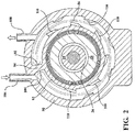
- the fluid chamber 86 has a circumferential extension of less than 360° relative to the longitudinal axis L. As illustrated in the cross-sectional view perpendicular to the longitudinal axis L of Fig. 2 , the fluid chamber 86 is further delimited by a longitudinal wall 94 in the stator housing body 62. This longitudinal wall 94 axially extends along the longitudinal axis L over the entire length of the fluid chamber 86 and, radially, from the radially inner wall 92 to the radially outer wall 90.
- the longitudinal wall 94 of the stator housing body 62 defines two ends 102, 104 of the fluid chamber 86 in the circumferential direction of the longitudinal axis L.
- the longitudinal wall 94 extends in the circumferential direction over approximately 10°, but could also extend over a larger (e.g., up to 90°) or smaller (e.g., less than 5°) angular range.
- the minimal circumferential extension of the longitudinal wall 94 and, thus, its minimal thickness will typically be defined by the casting process chosen for manufacturing the stator housing body 62.
- the fluid chamber 86 comprises an inlet 106 and an outlet 108.
- the outlet 108 is shown in the cross-sectional view illustrated in Fig. 1 .
- Each of the inlet 106 and the outlet 108 is defined as a bore that penetrates the radially outer wall 90 of the fluid chamber 86.
- the inlet 106 is spaced apart from the outlet 108 in a circumferential direction relative to the longitudinal axis L. In an axial direction, the inlet 106 and the outlet 108 have the same axial position (i.e., a distance of zero) relative to the longitudinal axis L.
- the inlet 106 and the outlet 108 are both located adjacent to the protrusion 96 of the cover 66. In other words, the inlet 106 and the outlet 108 are both located in a region of the fluid chamber 86 where the radial distance between the radially inner wall 92 and the radially outer wall 90 is larger than an average radial distance between the radially inner wall 92 and the radially outer wall 90 along the longitudinal axis L.
- each fluid flow deflector 110 is arranged in the fluid chamber 86 in a region between the radially inner wall 92 and the radially outer wall 90.
- the fluid flow deflectors 110 are generally configured as structures respectively protruding from a bottom of the radially inner wall 92 and a bottom of the radially outer wall 90 into the fluid chamber 86.
- Each fluid flow deflector 110 has an axial extension along the longitudinal axis L. In typical realizations, each fluid flow deflector 110 extends over at least 50% (e.g., more than 75% and up to 100%) of the axial length of the fluid chamber 86. In an axial direction, the fluid flow deflectors 110 are spaced apart from both the end 88A of the fluid chamber 86 facing the compressor housing 14 and the end 88B of the fluid chamber 86 adjacent to the cover 66.
- Each fluid flow deflector 110 is configured and arranged to deflect a portion of a cooling fluid flow away from a shortest path between the inlet 106 and the outlet 108.
- that shortest path extends in a circumferential direction from the inlet 106 to the outlet 108. Since the fluid chamber 86 is delimited in the circumferential direction by the longitudinal wall 94 (see also reference numerals 102 and 104 in Fig. 2 ), the shortest path extends circumferentially over approximately 300° in a fluid flow direction from the inlet 106 to the outlet 108. It will be appreciated that in other embodiments, the shortest path may at least partially extend in an axial direction of the longitudinal axis L (i.e., when the inlet 106 and outlet 108 are solely, or additionally, spaced apart in the longitudinal direction).
- the fluid flow deflectors 110 direct the cooling fluid flow in an axial direction of the longitudinal axis L. This means that the fluid flow deflectors 110 impart a velocity vector component on the cooling fluid flow that extends axially, as will now be explained with reference to Fig. 3.
- Fig. 3 schematically illustrates a winding off of the arcuate radially outer wall 90 in an imaginary plane.
- a velocity of the cooling fluid flow in the circumferential direction of the fluid chamber 86 downstream of the inlet 106 and upstream of one of the fluid flow deflectors 110 may be represented by a vector V, as shown in Fig. 3.
- Fig. 3 also schematically illustrates two of the fluid flow deflectors 110 of Figs. 1 and 2 .
- Each fluid flow deflector 110 has a leading edge E and a trailing edge T.
- the leading edge E is part of a leading surface that is configured to impart an axial velocity vector component A along the longitudinal axis L on a portion of the circumferentially directed cooling fluid flow.
- the axial velocity vector component A thus is directed perpendicular to the vector V and towards the end 88A of the fluid chamber 86 that faces the compressor housing 14 (where the fluid chamber 86 has its minimal radial extension). Due to the limited height of each fluid flow deflector 110, not the entire cooling fluid flow will be re-directed from the circumferential direction, but only a portion thereof. This is also illustrated in Fig. 3 by two vectors V that pass the fluid flow deflector 110 without being deflected.
- the leading edge E extends obliquely, or diagonally, relative to both the longitudinal axis L and the circumferential direction of the longitudinal axis L.
- This geometric relationship is illustrated in Fig. 3 by a projection of the longitudinal axis L on the radially outer wall 90.
- the leading edge E of the fluid flow deflector 110 extends at an angle ⁇ (i.e., diagonally) relative to the projection of the longitudinal axis L.
- ⁇ can be selected to be greater than 0° (e.g., greater than 15°) and smaller than or equal to 60° (e.g., smaller than or equal to 45°). In the embodiment illustrated in Fig. 3 , ⁇ is selected to equal approximately 20°.
- each fluid flow deflector 110 extends parallel to the longitudinal axis L. Therefore, the trailing edge T is also arranged at the angle ⁇ relative to the leading edge E.
- a maximum distance along the circumferential direction between the leading edge E and the trailing edge T may range between 2 mm and 20 mm (e.g., between 5 mm and 10 mm).
- each fluid flow deflector 110 will thus partially be deflected by each fluid flow deflector 110 from the shortest (i.e., circumferential) path between the inlet 106 to the outlet 108 and will at least partially be deflected in an axial direction towards the end of the fluid chamber 86 adjacent to the compressor housing 14.
- the cooling fluid flows through and absorbs heat in the entire fluid chamber 86. Therefore, the cooling fluid flow can transport absorbed heat away not just from the end of the stator housing 16 at which the inlet 106 and outlet 108 are located (i.e., adjacent to the cover 66), but also from the end of the fluid chamber 86 adjacent to the compressor housing 14. Consequently, the cooling efficiency can be increased.
- multiple fluid flow deflectors 110 are located on each of the radially inner wall 92 and the radially outer wall 90.
- five fluid flow deflectors 110 are located on the radially outer wall 90 and six fluid flow deflectors 110 are located on the radially inner wall 92, although these numbers may be varied.
- the fluid flow deflectors 110 on a particular one of the walls 90, 92 substantially have the same circumferential distance from each other.
- the fluid flow deflectors 110 are located on the two walls 90, 92 such that each fluid flow deflector 110 on the radially outer wall 90 is circumferentially positioned between two fluid flow deflectors 110 on the radially inner wall 92, and vice versa (except for the circumferentially outermost fluid flow deflectors 110).
- the fluid flow deflectors 110 each have an increasing height in a fluid flow direction (e.g., along the shortest path) from the inlet 106 to the outlet 108.
- the fluid flow deflectors 110 each have a maximum height that extends over approximately 10% to 30% of a radial distance between the radially outer wall 90 and the radially inner wall 92 (e.g., over approximately 1 mm to 2 mm).
- each fluid flow deflector 110 is configured as a step, leading to a sawtooth-like profile.
- the step acts as a break-away edge for the (substantially laminar) cooling fluid flow circumferentially along the inclined leading surface that comprises the leading surface E.
- turbulence is imparted on the cooling fluid flow at the trailing edge T so that swirls 112 are created in the cooling fluid flow circumferentially behind each trailing edge T. It has been found that such swirls 112 stabilize the cooling fluid flow in the circumferential direction and give rise to a reduced pressure loss between the inlet 106 and the outlet 108.
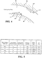
- the table of Fig. 5 provides a comparison of simulated heat flow-related parameters for a fluid chamber 86 as illustrated in Figs. 1 to 4 without and with the fluid flow deflectors 110.
- computational fluid dynamics (CFD) simulations using ANSYS AIM have been performed for a diameter of 8 mm for the inlet 106 and the outlet 108 as well as for two different mass flow rates of the cooling fluid.
- CFD computational fluid dynamics
Description
- The present disclosure relates to a compressor for an internal combustion engine. More particularly, the present disclosure relates to a stator housing for a fluid-cooled electrically driven compressor and to a fluid-cooled electrically driven compressor comprising this stator housing.
- Compressors deliver compressed air to an intake of an internal combustion engine, allowing more fuel to be combusted. As a result, a power density of the engine is increased without significantly increasing engine weight. Compressors thus permit the use of smaller engines that develop the same amount of power as larger, normally aspirated engines. Using a smaller engine in a vehicle has the desired effect of decreasing the vehicle mass, increasing performance and reducing fuel consumption. Moreover, the use of compressors leads to an improved combustion and, therefore, to reduced emissions.
- There exist different types of compressors. Exhaust gas turbochargers include a turbine housing having an inlet passage connected to an exhaust manifold of the engine, a compressor housing having an outlet passage connected to an intake manifold of the engine, and a bearing housing interconnecting the turbine housing and the compressor housing. An exhaust gas flow from the exhaust manifold rotatably drives a turbine wheel in the turbine housing. The turbine wheel is connected via a rotor shaft rotatably supported in the bearing housing to a compressor wheel in the compressor housing. Rotation of the turbine wheel by the exhaust gas flow thus causes rotation of the compressor wheel. The rotating compressor wheel draws ambient air via a so-called inducer into the compressor housing and compresses the air. Downstream of the compressor wheel the compressed air enters a diffusor channel from which the compressed air is guided via a compressor cover to the intake manifold.
- Electrically driven compressors, sometimes also called eBoosters, present an alternative to exhaust gas turbochargers. In electrically driven compressors, the rotor shaft, on which the compressor wheel is arranged, is driven by an electric motor, and not by the exhaust gas flow. For this purpose, a rotor of the electric motor is rotatably fixed to the rotor shaft and a stator of the electric motor circumferentially encloses the rotor. The stator is accommodated in a stator housing that is fixedly attached to the compressor housing.
- Electrically driven compressors tend to significantly heat up during operation, especially at high loads. It has therefore been proposed to circulate a cooling fluid through the stator housing so as to prevent thermal damage. A fluid-cooled electrically driven compressor of this type is known from
WO 2017/192336 A . The stator housing of this compressor comprises a fluid chamber delimited by a radially outer wall and a radially inner wall relative to a longitudinal axis of the stator housing. The fluid chamber has an inlet for the cooling fluid and an outlet. Furthermore,DE 10 2015 006348 A1 andDE 10 2014 204 816 A1 each disclose cooling fins arranged in a cooling jacket for cooling an electrical machine. - There is a need for a fluid-cooled electrically driven compressor with improved cooling efficiency. There also is a need for a stator housing for such a compressor.
- A stator housing for a fluid-cooled electrically driven compressor according to
claim 1 is presented. - The shortest path may extend in a circumferential direction of the longitudinal axis when the inlet and outlet are spaced apart in the circumferential direction. The shortest path may extend in an axial direction of the longitudinal axis when the inlet and outlet are spaced apart in the longitudinal direction. Moreover, the inlet and outlet may also be spaced apart in both the longitudinal and the circumferential direction of the longitudinal axis, so that the shortest path may have a helical extension (of typically less than 360°).
- Multiple fluid flow deflectors are located on each of the radially outer wall and the radially inner wall. An individual fluid flow deflector may extend from the inner wall to the outer wall. Alternatively, an individual fluid flow deflector may project from only one of the radially inner wall and the radially outer wall towards an interior of the chamber. One or more of the fluid flow deflectors project from the radially outer wall and one or more of the fluid flow deflectors project from the radially inner wall. An individual fluid flow deflector has a maximum height that projects over up to 50% or over up to 30% of a distance between the radially outer wall and the radially inner wall in the region of that fluid flow deflector. An individual fluid flow deflector may have a maximum height between 0,2 mm and 5 mm (e.g., between 0,5 mm and 3 mm), and a radial distance between the radially inner wall and the radially outer wall in the region of that fluid flow deflector may be larger than the maximum height.
- The multiple fluid flow deflectors may have an increasing height in a fluid flow direction (e.g., along the shortest path) from the inlet to the outlet. As an example, the multiple fluid flow deflectors may define an inclined surface over its region of increasing height. This inclined surface may be planar or curved, or may include both curved and planar surface regions. In the fluid flow direction the inclined surface may end at a step at which the height of the fluid flow deflector decreases again. The fluid flow deflectors may thus have a sawtooth-like profile.
- A velocity of the cooling fluid flow may be interpreted as a vector. The multiple fluid flow deflectors are configured to impart a velocity vector component on at least a portion of the cooling fluid flow. As an example, the imparted velocity vector component may extend along (i.e., parallel to) the longitudinal axis. The imparted velocity vector component generally has a direction different from a direction defined by the shortest path between the inlet and the outlet. This different direction may deviate from a direction of the shortest path in a region of an individual fluid flow deflector by up to 60° (e.g., by 15° to 45°).
- The multiple fluid flow deflectors may have a leading surface relative to a fluid flow direction. As mentioned above, the leading surface may be an inclined surface. The leading surface may have a leading edge that extends obliquely relative to at least one of the longitudinal axis and the circumferential direction of the longitudinal axis. As an example, the leading edge may extend non-parallel to the longitudinal axis and not in a plane that extends perpendicular to the longitudinal axis. In some variants, the leading edge of a particular fluid flow deflector is located at a transition between one of the radially inner wall and the radially outer wall and the particular fluid flow deflector.
- Additionally, or in the alternative, the multiple fluid flow deflectors may have a trailing edge that extends parallel to the longitudinal axis. An angle ϕ between the leading edge and the trailing edge may satisfy the following condition: 0° < ϕ ≤ 60° (e.g., 15° ≤ ϕ ≤ 45°). A maximum distance along the circumferential direction between the leading edge and the trailing edge may range between 2 mm and 20 mm (e.g., between 5 mm and 10 mm). In some variants, the trailing edge is configured as a step. The step may have a decreasing height. The step may be designed so as to impart turbulence on at least a portion of the cooling fluid flow that passes the fluid flow deflector.
- Multiple fluid flow deflectors are provided. The multiple fluid flow deflectors are spaced apart in a circumferential direction of the longitudinal axis (e.g., at an equidistant spacing in the circumferential direction). Each of the radially inner wall and the radially outer wall is provided with multiple fluid flow deflectors projecting therefrom. A fluid flow deflector on the radially outer wall may be located in a circumferential direction between two adjacent fluid flow deflectors on the radially inner wall. Additionally, or in the alternative, a fluid flow deflector on the radially inner wall may be located in a circumferential direction between two adjacent fluid flow deflectors on the radially outer wall.
- A radial distance between the radially inner wall and the radially outer wall may continuously decrease along the longitudinal axis. In such an implementation, at least one of the inlet and the outlet may be located in a region of the fluid chamber where the radial distance between the radially inner wall and the radially outer wall is larger than an average radial distance between the radially inner wall and the radially outer wall along the longitudinal axis.
- An axial distance between the inlet and the outlet along the longitudinal axis may be less than 25% of a length of the stator housing along the longitudinal axis. In particular, the axial distance between the inlet and the outlet along the longitudinal axis may substantially be zero.
- The outlet may be spaced apart from the inlet in a circumferential direction of the longitudinal axis. The outlet and the inlet may be provided at opposite ends of the chamber in the circumferential direction. In some variants, the outlet may be spaced apart from the inlet by more than 180° or more than 270° in a circumferential flow direction of the cooling fluid relative to the longitudinal axis.
- The fluid chamber may extend in a circumferential direction of the longitudinal axis over more than 60° or more than 90°. In particular, the fluid chamber may extend in a circumferential direction of the longitudinal axis over more than 180° or more than 270°. The chamber may extend in a circumferential direction of the longitudinal axis over less than 360° (e.g., over less than 350°). The remaining more than 0° or more than 10°, respectively, may be defined by a fluid chamber wall longitudinally extending along the longitudinal axis and radially extending from the radially inner wall to the radially outer wall. The wall may longitudinally extend over the entire length of the fluid chamber.
- At least one of the inlet and the outlet is defined by a bore. The respective bore may penetrate the radially outer wall of the fluid chamber.
- The stator housing is configured to comprise the stator of the electric motor, wherein the stator is received in the stator opening. In some variants, the stator may define the radially inner wall of the cooling fluid chamber. As an example, the stator may have a substantially cylindrical outer wall that defines the radially inner wall of the cooling fluid chamber. One or more fluid flow deflectors may extend from the substantially cylindrical outer wall of the stator (that forms the radially inner wall of the fluid chamber) towards the radially outer wall of the fluid chamber. Both the radially outer wall and the radially inner wall may be integral components of the stator housing.
- Also provided is a fluid-cooled electrically driven compressor comprising the stator housing presented herein.
- Additional aspects and advantages of the present disclosure will be readily appreciated by reference to the following detailed description when considered in connection with the accompanying drawings, wherein:
- Fig. 1
- is a first cross-sectional view of a fluid fluid-cooled electrically driven compressor according to one embodiment of the present disclosure, wherein the cross-section is taken along a longitudinal axis of the compressor;
- Fig. 2
- is a second cross-sectional view of the compressor of
Fig. 1 , wherein the cross-section is taken perpendicular to the longitudinal axis of the compressor; - Fig. 3
- is a schematic planar view of fluid flow deflectors and illustrates fluid flow deflection away from a shortest path along the longitudinal axis;
- Fig. 4
- is a schematic cross-sectional view of a fluid chamber and illustrates generation of turbulences at trailing ends of the fluid flow deflectors; and
- Fig. 5
- is a table comparing simulated heat flow-related parameters for a fluid chamber without and with fluid flow deflectors.
-
Fig. 1 illustrates an embodiment of a fluid-cooled electrically drivencompressor 10 for an internal combustion engine. Thecompressor 10 includes ahousing assembly 12 consisting of acompressor housing 14 and astator housing 16 that are connected to each other. - The
housing assembly 12 rotatably supports arotor shaft 20 having an axis of rotation R.A compressor wheel 22 with a plurality of blades is mounted on one end of theshaft 20 that is accommodated in thecompressor housing 14. Arotor 24 of anelectric motor 26 is mounted on an opposite end of theshaft 20 in relation to thecompressor wheel 22. Therotor 24 is accommodated together with astator 28 of theelectric motor 26 in thestator housing 16. During operation of theelectric motor 26, therotor 24 and theshaft 20 with thecompressor wheel 22 rotate relative to thestator 28, as is known in the art. - The
compressor housing 14 includes aninlet passage 40. Thisinlet passage 40 is also referred to as inducer. Upon rotation of thecompressor wheel 22, ambient air is drawn into thecompressor housing 14 through theinlet passage 40 and compressed by thecompressor wheel 22. Downstream of thecompressor wheel 22 the compressed air enters adiffusor channel 42 from which the compressed air is guided via anoutlet passage 44 in the form of a volute to an intake manifold (not shown) of the engine. - The
diffusor channel 42 is defined between acompressor housing body 46 and abackplate 48 of thecompressor housing 14. Thebackplate 48 is substantially disk-shaped and has a diameter that is substantially larger than a diameter of thecompressor wheel 22 so as to delimit thediffusor channel 42 that extends in a radial direction away from thecompressor wheel 22. - The
backplate 48 comprises a central through-opening 56 that is seated on atubular protrusion 58 of thestator housing 14. Therotor shaft 20 extends through thistubular protrusion 58. Asleeve 60, also called flinger sleeve, is seated on therotor shaft 20 so as to rotate together with therotor shaft 20. - The
stator housing 16 has a longitudinal axis L that extends coaxial with the axis of rotation R. Thestator housing 16 comprises astator housing body 62 with a substantiallycylindrical opening 64 extending along the longitudinal axis L and accommodating thestator 28. A printedcircuit board 30 with electrical components that electrically contact thestator 28 is mounted to thestator housing body 62 at its end facing thecompressor housing 14. On its end opposite thecompressor housing 14, thestator opening 64 is closed by acover 66. In the present embodiment, thecover 66 is attached to thestator housing body 62 via a screw connection. A first rotor bearing 68 for therotor shaft 20 is provided in thecover 66 and a second rotor bearing 70 is provided in thestator housing body 62 at its end opposite to thecover 66. The tworotor bearings - The
stator housing body 62 has a substantially hollow cylindrical shape defined by anouter wall 80 and aninner wall 82. Theinner wall 82 delimits thestator opening 64. Afluid chamber 86 in thestator housing body 62 is located between theouter wall 80 and theinner wall 82. Thefluid chamber 86 is part of a cooling fluid circuit that partially extends to an outside of thehousing assembly 12. In this cooling circuit, thefluid chamber 86 acts as a heat exchanger for transporting heat (generated, for example, by thestator 28 and the control components on the printed circuit board 30) to the outside of thehousing assembly 12. In one variant, water is used as a cooling fluid, but other cooling fluids may be used as well. - The
fluid chamber 86 extends along the longitudinal axis L from afirst end 88A facing thecompressor housing 14 to a second end adjacent thecover 66. Thefluid chamber 86 extends in a circumferential direction of the longitudinal axis L around thestator opening 64. In a radial direction of the longitudinal axis L, thefluid chamber 86 is delimited by a radiallyouter wall 90 and a radiallyinner wall 92. Each of the radiallyouter wall 90 and the radiallyinner wall 92 has a face adjacent thefluid chamber 86 that is inclined relative to the longitudinal axis L such that a radial distance between the radiallyinner wall 92 and the radiallyouter wall 90 continuously increases along the longitudinal axis L from theend 88A of thestator housing body 62 next to thecompressor housing 14 to theend 88B of thestator housing body 62 next to thecover 66. As such, each of the radiallyouter wall 90 and the radiallyinner wall 92 defines a substantially conical surface respectively having an increasing and decreasing diameter from an end of thestator housing body 62 next to thecompressor housing 14 to an end of thestator housing body 62 next to thecover 66. In other embodiments, at least one of the radiallyouter wall 90 and the radiallyinner wall 92 may define a cylindrical shape. Moreover, in such or other embodiments, the radial distance between the radiallyinner wall 92 and the radiallyouter wall 90 may substantially be constant along the longitudinal axis L. - The
stator housing body 62 is a cast metal part. Thefluid chamber 86 will be defined during the casting process by an axially movable slider or by a core in the mold. The slider is used in a die-casting process. As shown inFig. 1 , theend 88A of thefluid chamber 86 facing thecompressor housing 14 is concavely shaped towards an interior of thefluid chamber 86 for ease of manufacturing. - At its
end 88B facing thecover 66, thefluid chamber 86 is delimited by aringshaped protrusion 96 of thecover 66. Theprotrusion 96 axially extends into thefluid chamber 86. A radiallyinner sealing ring 98 and a radiallyouter sealing ring 100 are arranged between theprotrusion 96 on the one hand and, on the other hand, the radiallyinner wall 92 and the radiallyouter wall 90, respectively. - It is to be noted that the
fluid chamber 86 has a circumferential extension of less than 360° relative to the longitudinal axis L. As illustrated in the cross-sectional view perpendicular to the longitudinal axis L ofFig. 2 , thefluid chamber 86 is further delimited by alongitudinal wall 94 in thestator housing body 62. Thislongitudinal wall 94 axially extends along the longitudinal axis L over the entire length of thefluid chamber 86 and, radially, from the radiallyinner wall 92 to the radiallyouter wall 90. - As shown in
Fig. 2 , thelongitudinal wall 94 of thestator housing body 62 defines two ends 102, 104 of thefluid chamber 86 in the circumferential direction of the longitudinal axis L. Thelongitudinal wall 94 extends in the circumferential direction over approximately 10°, but could also extend over a larger (e.g., up to 90°) or smaller (e.g., less than 5°) angular range. The minimal circumferential extension of thelongitudinal wall 94 and, thus, its minimal thickness will typically be defined by the casting process chosen for manufacturing thestator housing body 62. - As further shown in
Fig. 2 , thefluid chamber 86 comprises aninlet 106 and anoutlet 108. In the cross-sectional view illustrated inFig. 1 , only theoutlet 108 is shown. Each of theinlet 106 and theoutlet 108 is defined as a bore that penetrates the radiallyouter wall 90 of thefluid chamber 86. Theinlet 106 is spaced apart from theoutlet 108 in a circumferential direction relative to the longitudinal axis L. In an axial direction, theinlet 106 and theoutlet 108 have the same axial position (i.e., a distance of zero) relative to the longitudinal axis L. - The
inlet 106 and theoutlet 108 are both located adjacent to theprotrusion 96 of thecover 66. In other words, theinlet 106 and theoutlet 108 are both located in a region of thefluid chamber 86 where the radial distance between the radiallyinner wall 92 and the radiallyouter wall 90 is larger than an average radial distance between the radiallyinner wall 92 and the radiallyouter wall 90 along the longitudinal axis L. - As becomes apparent from
Fig. 2 , multiplefluid flow deflectors 110 are arranged in thefluid chamber 86 in a region between the radiallyinner wall 92 and the radiallyouter wall 90. Thefluid flow deflectors 110 are generally configured as structures respectively protruding from a bottom of the radiallyinner wall 92 and a bottom of the radiallyouter wall 90 into thefluid chamber 86. Eachfluid flow deflector 110 has an axial extension along the longitudinal axis L. In typical realizations, eachfluid flow deflector 110 extends over at least 50% (e.g., more than 75% and up to 100%) of the axial length of thefluid chamber 86. In an axial direction, thefluid flow deflectors 110 are spaced apart from both theend 88A of thefluid chamber 86 facing thecompressor housing 14 and theend 88B of thefluid chamber 86 adjacent to thecover 66. - Each
fluid flow deflector 110 is configured and arranged to deflect a portion of a cooling fluid flow away from a shortest path between theinlet 106 and theoutlet 108. In the embodiment depicted in the drawings, that shortest path extends in a circumferential direction from theinlet 106 to theoutlet 108. Since thefluid chamber 86 is delimited in the circumferential direction by the longitudinal wall 94 (see alsoreference numerals Fig. 2 ), the shortest path extends circumferentially over approximately 300° in a fluid flow direction from theinlet 106 to theoutlet 108. It will be appreciated that in other embodiments, the shortest path may at least partially extend in an axial direction of the longitudinal axis L (i.e., when theinlet 106 andoutlet 108 are solely, or additionally, spaced apart in the longitudinal direction). - In order to deflect the cooling fluid flow away from the shortest path between the
inlet 106 and the outlet 108 (i.e., in the present embodiment away from the circumferential direction), thefluid flow deflectors 110 direct the cooling fluid flow in an axial direction of the longitudinal axis L. This means that thefluid flow deflectors 110 impart a velocity vector component on the cooling fluid flow that extends axially, as will now be explained with reference toFig. 3. Fig. 3 schematically illustrates a winding off of the arcuate radiallyouter wall 90 in an imaginary plane. - A velocity of the cooling fluid flow in the circumferential direction of the
fluid chamber 86 downstream of theinlet 106 and upstream of one of thefluid flow deflectors 110 may be represented by a vector V, as shown inFig. 3. Fig. 3 also schematically illustrates two of thefluid flow deflectors 110 ofFigs. 1 and2 . Eachfluid flow deflector 110 has a leading edge E and a trailing edge T. The leading edge E is part of a leading surface that is configured to impart an axial velocity vector component A along the longitudinal axis L on a portion of the circumferentially directed cooling fluid flow. The axial velocity vector component A thus is directed perpendicular to the vector V and towards theend 88A of thefluid chamber 86 that faces the compressor housing 14 (where thefluid chamber 86 has its minimal radial extension). Due to the limited height of eachfluid flow deflector 110, not the entire cooling fluid flow will be re-directed from the circumferential direction, but only a portion thereof. This is also illustrated inFig. 3 by two vectors V that pass thefluid flow deflector 110 without being deflected. - The leading edge E extends obliquely, or diagonally, relative to both the longitudinal axis L and the circumferential direction of the longitudinal axis L. This geometric relationship is illustrated in
Fig. 3 by a projection of the longitudinal axis L on the radiallyouter wall 90. As shown inFig. 3 , the leading edge E of thefluid flow deflector 110 extends at an angle ϕ (i.e., diagonally) relative to the projection of the longitudinal axis L. In general, ϕ can be selected to be greater than 0° (e.g., greater than 15°) and smaller than or equal to 60° (e.g., smaller than or equal to 45°). In the embodiment illustrated inFig. 3 , ϕ is selected to equal approximately 20°. - The trailing edge T of each
fluid flow deflector 110 extends parallel to the longitudinal axis L. Therefore, the trailing edge T is also arranged at the angle ϕ relative to the leading edge E. A maximum distance along the circumferential direction between the leading edge E and the trailing edge T may range between 2 mm and 20 mm (e.g., between 5 mm and 10 mm). - The cooling fluid flow will thus partially be deflected by each
fluid flow deflector 110 from the shortest (i.e., circumferential) path between theinlet 106 to theoutlet 108 and will at least partially be deflected in an axial direction towards the end of thefluid chamber 86 adjacent to thecompressor housing 14. As a result, the cooling fluid flows through and absorbs heat in theentire fluid chamber 86. Therefore, the cooling fluid flow can transport absorbed heat away not just from the end of thestator housing 16 at which theinlet 106 andoutlet 108 are located (i.e., adjacent to the cover 66), but also from the end of thefluid chamber 86 adjacent to thecompressor housing 14. Consequently, the cooling efficiency can be increased. - As shown in
Figs. 2 and3 , multiplefluid flow deflectors 110 are located on each of the radiallyinner wall 92 and the radiallyouter wall 90. In the embodiment illustrated in the drawings, fivefluid flow deflectors 110 are located on the radiallyouter wall 90 and sixfluid flow deflectors 110 are located on the radiallyinner wall 92, although these numbers may be varied. Thefluid flow deflectors 110 on a particular one of thewalls fluid flow deflectors 110 are located on the twowalls fluid flow deflector 110 on the radiallyouter wall 90 is circumferentially positioned between twofluid flow deflectors 110 on the radiallyinner wall 92, and vice versa (except for the circumferentially outermost fluid flow deflectors 110). - As becomes apparent from
Fig. 2 , and now with additional reference toFig. 4 , thefluid flow deflectors 110 each have an increasing height in a fluid flow direction (e.g., along the shortest path) from theinlet 106 to theoutlet 108.. Thefluid flow deflectors 110 each have a maximum height that extends over approximately 10% to 30% of a radial distance between the radiallyouter wall 90 and the radially inner wall 92 (e.g., over approximately 1 mm to 2 mm). - As illustrated in
Fig. 4 , the trailing edge T of eachfluid flow deflector 110 is configured as a step, leading to a sawtooth-like profile. The step acts as a break-away edge for the (substantially laminar) cooling fluid flow circumferentially along the inclined leading surface that comprises the leading surface E. As a result, turbulence is imparted on the cooling fluid flow at the trailing edge T so that swirls 112 are created in the cooling fluid flow circumferentially behind each trailing edge T. It has been found thatsuch swirls 112 stabilize the cooling fluid flow in the circumferential direction and give rise to a reduced pressure loss between theinlet 106 and theoutlet 108. - As a result of the
fluid flow deflectors 110 deflecting the cooling fluid flow away from the shortest path between theinlet 106 and theoutlet 108, and thus distributing the cooling fluid flows through theentire fluid chamber 86, the cooling fluid in thefluid chamber 86 assumes a more uniform temperature distribution. Consequently, heat is prevented from "accumulating" at the end of thefluid chamber 86 adjacent to thecompressor housing 14, and cooling efficiency is increased. This increase in cooling efficiency becomes apparent from the table ofFig. 5 . - The table of
Fig. 5 provides a comparison of simulated heat flow-related parameters for afluid chamber 86 as illustrated inFigs. 1 to 4 without and with thefluid flow deflectors 110. To this end, computational fluid dynamics (CFD) simulations using ANSYS AIM have been performed for a diameter of 8 mm for theinlet 106 and theoutlet 108 as well as for two different mass flow rates of the cooling fluid. As becomes apparent from the table, the temperature difference ΔT of the cooling fluid between theoutlet 108 and theinlet 106 is increased whenfluid flow deflectors 110 are provided, which means that the heat flow from thestator housing 16 to the cooling fluid is increased also. Consequently, the cooling efficiency is improved. At the same time, pressure losses between theinlet 106 and theoutlet 108 are decreased in the presence of thefluid flow deflectors 110, which is due to turbulences formed at the trailing edges T of thefluid flow deflectors 110 and to the resulting stabilization of the cooling fluid flow as a whole from theinlet 106 to theoutlet 108. - The invention has been described here in an illustrative manner, and it is to be understood that modifications and variations are possible in light of the above teachings. It is, therefore, to be understood that the invention may be practiced in other embodiments while still being covered by the claims that follow.
Claims (13)
- A stator housing (16) for a fluid-cooled electrically driven compressor (10) of an internal combustion engine, the stator housing (16) having a longitudinal axis (L) and comprisinga stator opening (64) extending along the longitudinal axis (L) and configured to receive a stator (28) of an electric motor (26); anda fluid chamber (86) having a fluid inlet (106) and a fluid outlet (108) and extending in a circumferential direction of the longitudinal axis (L) around the stator opening (64), wherein the fluid chamber (86) is delimited by a radially outer wall (90) and a radially inner wall (92) relative to the longitudinal axis (L),whereinmultiple fluid flow deflectors (110) are arranged in a region between the radially outer wall (90) and the radially inner wall (92) and spaced apart in a circumferential direction of the longitudinal axis (L) and configured to deflect at least a portion of a cooling fluid flow away from a shortest path between the inlet (106) and the outlet (108), characterised in that one or more of the fluid flow deflectors project from the radially outer wall and one or more of the fluid flow deflectors project from the radially inner wall.
- The stator housing (16) of claim 1, wherein
the fluid flow deflectors (110) have an increasing height in a fluid flow direction from the inlet (106) to the outlet (108). - The stator housing (16) of any of the preceding claims, wherein
the fluid flow deflectors (110) are configured to impart a velocity component (A) on at least a portion of the cooling fluid flow, wherein the velocity component (A) extends along the longitudinal axis (L). - The stator housing (16) of any of the preceding claims, wherein
the fluid flow deflectors (110) have a leading surface with a leading edge (E), wherein the leading edge (E) extends obliquely relative to at least one of the longitudinal axis (L) and the circumferential direction of the longitudinal axis (L). - The stator housing (16) of any of the preceding claims, wherein
the fluid flow deflectors (110) have a trailing edge (T) that extends parallel to the longitudinal axis (L). - The stator housing (16) of claim 5, wherein
the trailing edge (T) is configured as a step. - The stator housing (16) of claims 4 and 5 or 4, 5 and 6, wherein
for an angle ϕ between the leading edge (E) and the trailing edge (T) the following condition holds: 0 < ϕ ≤ 60°. - The stator housing (16) of claim 1, wherein
for the multiple fluid flow deflectors (110) at least one of the following two conditions holds:- a fluid flow deflector (110) on the radially outer wall (90) is located in a circumferential direction between two adjacent fluid flow deflectors (110) on the radially inner wall (92); and- a fluid flow deflector (110) on the radially inner wall (92) is located in a circumferential direction between two adjacent fluid flow deflectors (110) on the radially outer wall (90). - The stator housing (16) of any of the preceding claims, wherein
an axial distance between the inlet (106) and the outlet (108) along the longitudinal axis (L) is less than 25% of a length of the stator housing (16) along the longitudinal axis (L). - The stator housing (16) of any of the preceding claims, wherein
the outlet (108) is spaced apart from the inlet (106) in a circumferential direction of the longitudinal axis (L). - The stator housing (16) of any of the preceding claims, wherein
the fluid chamber (86) extends in a circumferential direction of the longitudinal axis (L) over less than 360°. - The stator housing (16) of any of the preceding claims, further comprising
the stator (28), wherein the stator (28) is received in the stator opening (64) and defines the radially inner wall (92) of the cooling fluid chamber (86). - A fluid-cooled electrically driven compressor (10) of an internal combustion
engine, the compressor (10) comprising the stator housing (16) of any of the preceding claims.
Priority Applications (3)
| Application Number | Priority Date | Filing Date | Title |
|---|---|---|---|
| EP19169231.8A EP3726063B1 (en) | 2019-04-15 | 2019-04-15 | Fluid-cooled electrically driven compressor and stator housing therefor |
| CN201910459698.6A CN111828397A (en) | 2019-04-15 | 2019-05-30 | Fluid-cooled electrically-driven compressor and stator housing therefor |
| CN201920799901.XU CN210599579U (en) | 2019-04-15 | 2019-05-30 | Fluid-cooled electrically-driven compressor and stator housing therefor |
Applications Claiming Priority (1)
| Application Number | Priority Date | Filing Date | Title |
|---|---|---|---|
| EP19169231.8A EP3726063B1 (en) | 2019-04-15 | 2019-04-15 | Fluid-cooled electrically driven compressor and stator housing therefor |
Publications (2)
| Publication Number | Publication Date |
|---|---|
| EP3726063A1 EP3726063A1 (en) | 2020-10-21 |
| EP3726063B1 true EP3726063B1 (en) | 2021-11-24 |
Family
ID=66182414
Family Applications (1)
| Application Number | Title | Priority Date | Filing Date |
|---|---|---|---|
| EP19169231.8A Active EP3726063B1 (en) | 2019-04-15 | 2019-04-15 | Fluid-cooled electrically driven compressor and stator housing therefor |
Country Status (2)
| Country | Link |
|---|---|
| EP (1) | EP3726063B1 (en) |
| CN (2) | CN210599579U (en) |
Citations (1)
| Publication number | Priority date | Publication date | Assignee | Title |
|---|---|---|---|---|
| US20150308456A1 (en) * | 2014-02-19 | 2015-10-29 | Honeywell International Inc. | Electric motor-driven compressor having bi-directional liquid coolant passage |
Family Cites Families (8)
| Publication number | Priority date | Publication date | Assignee | Title |
|---|---|---|---|---|
| US3060335A (en) * | 1961-02-07 | 1962-10-23 | Garrett Corp | Fluid cooled dynamoelectric machine |
| JPH08281317A (en) * | 1995-04-06 | 1996-10-29 | Bridgestone Metalpha Kk | System for cooling power reel for wire |
| EP0878897A1 (en) * | 1997-05-13 | 1998-11-18 | General Motors Corporation | Electric motor or generator |
| US8435015B2 (en) * | 2008-12-16 | 2013-05-07 | Baker Hughes Incorporated | Heat transfer through the electrical submersible pump |
| DE102014204816A1 (en) * | 2014-03-14 | 2015-09-17 | Zf Friedrichshafen Ag | Electric machine with a cooling element |
| WO2015176703A1 (en) * | 2014-05-20 | 2015-11-26 | Schaeffler Technologies AG & Co. KG | Installation space optimized cooling jacket comprising a separator bar having a bracket for an electrical machine |
| US20160294231A1 (en) * | 2015-04-02 | 2016-10-06 | Hamilton Sundstrand Corporation | Stator heat transfer feature |
| US10971974B2 (en) | 2016-05-04 | 2021-04-06 | Borgwarner Inc. | Electric charging device with fluid cooling |
-
2019
- 2019-04-15 EP EP19169231.8A patent/EP3726063B1/en active Active
- 2019-05-30 CN CN201920799901.XU patent/CN210599579U/en active Active
- 2019-05-30 CN CN201910459698.6A patent/CN111828397A/en active Pending
Patent Citations (1)
| Publication number | Priority date | Publication date | Assignee | Title |
|---|---|---|---|---|
| US20150308456A1 (en) * | 2014-02-19 | 2015-10-29 | Honeywell International Inc. | Electric motor-driven compressor having bi-directional liquid coolant passage |
Also Published As
| Publication number | Publication date |
|---|---|
| CN210599579U (en) | 2020-05-22 |
| EP3726063A1 (en) | 2020-10-21 |
| CN111828397A (en) | 2020-10-27 |
Similar Documents
| Publication | Publication Date | Title |
|---|---|---|
| US8845269B2 (en) | Compressor casing with optimized cavities | |
| EP2617961B1 (en) | Radial turbine | |
| JP4819872B2 (en) | Introduction of spiral air | |
| US20060207239A1 (en) | Compact mixer with trimmable open centerbody | |
| US8206080B2 (en) | Gas turbine engine with improved thermal isolation | |
| US8172524B2 (en) | Fan including specific stationary vane arrangement | |
| JP2007113501A (en) | Exhaust gas turbocharger | |
| CN108026931A (en) | With heat sink turbofan | |
| EP2943726B1 (en) | Air handling unit | |
| CN108952967B (en) | Turbojet engine with improved air system | |
| JP2006144789A (en) | Method and device for cooling external shroud of gas turbine rotor blade | |
| US8002521B2 (en) | Flow machine | |
| US9677418B2 (en) | Turbine housing and turbocharger | |
| US9816395B2 (en) | Turbine housing | |
| HUT77149A (en) | Arrangement of conductor bars | |
| EP3726063B1 (en) | Fluid-cooled electrically driven compressor and stator housing therefor | |
| US9638058B2 (en) | Scroll portion structure for radial turbine or diagonal flow turbine | |
| US6914355B2 (en) | Common radial plane motor cooling | |
| US11125435B2 (en) | Bent combustion chamber from a turbine engine | |
| US11319964B2 (en) | Turbocharger and bearing housing therefor | |
| JP7105823B2 (en) | supercharger | |
| WO2022208839A1 (en) | Supercharger | |
| EP4033070A1 (en) | Impingement baffle for gas turbine engine | |
| CN110234855B (en) | Housing of turbine for exhaust turbocharger, and manufacturing method | |
| JP2024011501A (en) | gas turbine |
Legal Events
| Date | Code | Title | Description |
|---|---|---|---|
| PUAI | Public reference made under article 153(3) epc to a published international application that has entered the european phase |
Free format text: ORIGINAL CODE: 0009012 |
|
| STAA | Information on the status of an ep patent application or granted ep patent |
Free format text: STATUS: REQUEST FOR EXAMINATION WAS MADE |
|
| 17P | Request for examination filed |
Effective date: 20200714 |
|
| AK | Designated contracting states |
Kind code of ref document: A1 Designated state(s): AL AT BE BG CH CY CZ DE DK EE ES FI FR GB GR HR HU IE IS IT LI LT LU LV MC MK MT NL NO PL PT RO RS SE SI SK SM TR |
|
| AX | Request for extension of the european patent |
Extension state: BA ME |
|
| GRAP | Despatch of communication of intention to grant a patent |
Free format text: ORIGINAL CODE: EPIDOSNIGR1 |
|
| STAA | Information on the status of an ep patent application or granted ep patent |
Free format text: STATUS: GRANT OF PATENT IS INTENDED |
|
| RIC1 | Information provided on ipc code assigned before grant |
Ipc: F04D 29/58 20060101AFI20210521BHEP Ipc: H02K 9/19 20060101ALI20210521BHEP Ipc: H02K 5/12 20060101ALI20210521BHEP Ipc: F04D 17/10 20060101ALI20210521BHEP Ipc: F04D 25/06 20060101ALI20210521BHEP |
|
| INTG | Intention to grant announced |
Effective date: 20210618 |
|
| GRAS | Grant fee paid |
Free format text: ORIGINAL CODE: EPIDOSNIGR3 |
|
| GRAA | (expected) grant |
Free format text: ORIGINAL CODE: 0009210 |
|
| STAA | Information on the status of an ep patent application or granted ep patent |
Free format text: STATUS: THE PATENT HAS BEEN GRANTED |
|
| AK | Designated contracting states |
Kind code of ref document: B1 Designated state(s): AL AT BE BG CH CY CZ DE DK EE ES FI FR GB GR HR HU IE IS IT LI LT LU LV MC MK MT NL NO PL PT RO RS SE SI SK SM TR |
|
| REG | Reference to a national code |
Ref country code: GB Ref legal event code: FG4D |
|
| REG | Reference to a national code |
Ref country code: AT Ref legal event code: REF Ref document number: 1450073 Country of ref document: AT Kind code of ref document: T Effective date: 20211215 |
|
| REG | Reference to a national code |
Ref country code: DE Ref legal event code: R096 Ref document number: 602019009449 Country of ref document: DE |
|
| REG | Reference to a national code |
Ref country code: IE Ref legal event code: FG4D |
|
| REG | Reference to a national code |
Ref country code: LT Ref legal event code: MG9D |
|
| REG | Reference to a national code |
Ref country code: NL Ref legal event code: MP Effective date: 20211124 |
|
| REG | Reference to a national code |
Ref country code: AT Ref legal event code: MK05 Ref document number: 1450073 Country of ref document: AT Kind code of ref document: T Effective date: 20211124 |
|
| PG25 | Lapsed in a contracting state [announced via postgrant information from national office to epo] |
Ref country code: RS Free format text: LAPSE BECAUSE OF FAILURE TO SUBMIT A TRANSLATION OF THE DESCRIPTION OR TO PAY THE FEE WITHIN THE PRESCRIBED TIME-LIMIT Effective date: 20211124 Ref country code: LT Free format text: LAPSE BECAUSE OF FAILURE TO SUBMIT A TRANSLATION OF THE DESCRIPTION OR TO PAY THE FEE WITHIN THE PRESCRIBED TIME-LIMIT Effective date: 20211124 Ref country code: FI Free format text: LAPSE BECAUSE OF FAILURE TO SUBMIT A TRANSLATION OF THE DESCRIPTION OR TO PAY THE FEE WITHIN THE PRESCRIBED TIME-LIMIT Effective date: 20211124 Ref country code: BG Free format text: LAPSE BECAUSE OF FAILURE TO SUBMIT A TRANSLATION OF THE DESCRIPTION OR TO PAY THE FEE WITHIN THE PRESCRIBED TIME-LIMIT Effective date: 20220224 Ref country code: AT Free format text: LAPSE BECAUSE OF FAILURE TO SUBMIT A TRANSLATION OF THE DESCRIPTION OR TO PAY THE FEE WITHIN THE PRESCRIBED TIME-LIMIT Effective date: 20211124 |
|
| PG25 | Lapsed in a contracting state [announced via postgrant information from national office to epo] |
Ref country code: IS Free format text: LAPSE BECAUSE OF FAILURE TO SUBMIT A TRANSLATION OF THE DESCRIPTION OR TO PAY THE FEE WITHIN THE PRESCRIBED TIME-LIMIT Effective date: 20220324 Ref country code: SE Free format text: LAPSE BECAUSE OF FAILURE TO SUBMIT A TRANSLATION OF THE DESCRIPTION OR TO PAY THE FEE WITHIN THE PRESCRIBED TIME-LIMIT Effective date: 20211124 Ref country code: PT Free format text: LAPSE BECAUSE OF FAILURE TO SUBMIT A TRANSLATION OF THE DESCRIPTION OR TO PAY THE FEE WITHIN THE PRESCRIBED TIME-LIMIT Effective date: 20220324 Ref country code: PL Free format text: LAPSE BECAUSE OF FAILURE TO SUBMIT A TRANSLATION OF THE DESCRIPTION OR TO PAY THE FEE WITHIN THE PRESCRIBED TIME-LIMIT Effective date: 20211124 Ref country code: NO Free format text: LAPSE BECAUSE OF FAILURE TO SUBMIT A TRANSLATION OF THE DESCRIPTION OR TO PAY THE FEE WITHIN THE PRESCRIBED TIME-LIMIT Effective date: 20220224 Ref country code: NL Free format text: LAPSE BECAUSE OF FAILURE TO SUBMIT A TRANSLATION OF THE DESCRIPTION OR TO PAY THE FEE WITHIN THE PRESCRIBED TIME-LIMIT Effective date: 20211124 Ref country code: LV Free format text: LAPSE BECAUSE OF FAILURE TO SUBMIT A TRANSLATION OF THE DESCRIPTION OR TO PAY THE FEE WITHIN THE PRESCRIBED TIME-LIMIT Effective date: 20211124 Ref country code: HR Free format text: LAPSE BECAUSE OF FAILURE TO SUBMIT A TRANSLATION OF THE DESCRIPTION OR TO PAY THE FEE WITHIN THE PRESCRIBED TIME-LIMIT Effective date: 20211124 Ref country code: GR Free format text: LAPSE BECAUSE OF FAILURE TO SUBMIT A TRANSLATION OF THE DESCRIPTION OR TO PAY THE FEE WITHIN THE PRESCRIBED TIME-LIMIT Effective date: 20220225 |
|
| PG25 | Lapsed in a contracting state [announced via postgrant information from national office to epo] |
Ref country code: SM Free format text: LAPSE BECAUSE OF FAILURE TO SUBMIT A TRANSLATION OF THE DESCRIPTION OR TO PAY THE FEE WITHIN THE PRESCRIBED TIME-LIMIT Effective date: 20211124 Ref country code: SK Free format text: LAPSE BECAUSE OF FAILURE TO SUBMIT A TRANSLATION OF THE DESCRIPTION OR TO PAY THE FEE WITHIN THE PRESCRIBED TIME-LIMIT Effective date: 20211124 Ref country code: RO Free format text: LAPSE BECAUSE OF FAILURE TO SUBMIT A TRANSLATION OF THE DESCRIPTION OR TO PAY THE FEE WITHIN THE PRESCRIBED TIME-LIMIT Effective date: 20211124 Ref country code: ES Free format text: LAPSE BECAUSE OF FAILURE TO SUBMIT A TRANSLATION OF THE DESCRIPTION OR TO PAY THE FEE WITHIN THE PRESCRIBED TIME-LIMIT Effective date: 20211124 Ref country code: EE Free format text: LAPSE BECAUSE OF FAILURE TO SUBMIT A TRANSLATION OF THE DESCRIPTION OR TO PAY THE FEE WITHIN THE PRESCRIBED TIME-LIMIT Effective date: 20211124 Ref country code: DK Free format text: LAPSE BECAUSE OF FAILURE TO SUBMIT A TRANSLATION OF THE DESCRIPTION OR TO PAY THE FEE WITHIN THE PRESCRIBED TIME-LIMIT Effective date: 20211124 Ref country code: CZ Free format text: LAPSE BECAUSE OF FAILURE TO SUBMIT A TRANSLATION OF THE DESCRIPTION OR TO PAY THE FEE WITHIN THE PRESCRIBED TIME-LIMIT Effective date: 20211124 |
|
| REG | Reference to a national code |
Ref country code: DE Ref legal event code: R097 Ref document number: 602019009449 Country of ref document: DE |
|
| PLBE | No opposition filed within time limit |
Free format text: ORIGINAL CODE: 0009261 |
|
| STAA | Information on the status of an ep patent application or granted ep patent |
Free format text: STATUS: NO OPPOSITION FILED WITHIN TIME LIMIT |
|
| PG25 | Lapsed in a contracting state [announced via postgrant information from national office to epo] |
Ref country code: AL Free format text: LAPSE BECAUSE OF FAILURE TO SUBMIT A TRANSLATION OF THE DESCRIPTION OR TO PAY THE FEE WITHIN THE PRESCRIBED TIME-LIMIT Effective date: 20211124 |
|
| 26N | No opposition filed |
Effective date: 20220825 |
|
| PG25 | Lapsed in a contracting state [announced via postgrant information from national office to epo] |
Ref country code: SI Free format text: LAPSE BECAUSE OF FAILURE TO SUBMIT A TRANSLATION OF THE DESCRIPTION OR TO PAY THE FEE WITHIN THE PRESCRIBED TIME-LIMIT Effective date: 20211124 |
|
| REG | Reference to a national code |
Ref country code: CH Ref legal event code: PL |
|
| REG | Reference to a national code |
Ref country code: BE Ref legal event code: MM Effective date: 20220430 |
|
| PG25 | Lapsed in a contracting state [announced via postgrant information from national office to epo] |
Ref country code: MC Free format text: LAPSE BECAUSE OF FAILURE TO SUBMIT A TRANSLATION OF THE DESCRIPTION OR TO PAY THE FEE WITHIN THE PRESCRIBED TIME-LIMIT Effective date: 20211124 Ref country code: LU Free format text: LAPSE BECAUSE OF NON-PAYMENT OF DUE FEES Effective date: 20220415 Ref country code: LI Free format text: LAPSE BECAUSE OF NON-PAYMENT OF DUE FEES Effective date: 20220430 Ref country code: FR Free format text: LAPSE BECAUSE OF NON-PAYMENT OF DUE FEES Effective date: 20220430 Ref country code: CH Free format text: LAPSE BECAUSE OF NON-PAYMENT OF DUE FEES Effective date: 20220430 |
|
| PG25 | Lapsed in a contracting state [announced via postgrant information from national office to epo] |
Ref country code: BE Free format text: LAPSE BECAUSE OF NON-PAYMENT OF DUE FEES Effective date: 20220430 |
|
| PG25 | Lapsed in a contracting state [announced via postgrant information from national office to epo] |
Ref country code: IE Free format text: LAPSE BECAUSE OF NON-PAYMENT OF DUE FEES Effective date: 20220415 |
|
| PG25 | Lapsed in a contracting state [announced via postgrant information from national office to epo] |
Ref country code: IT Free format text: LAPSE BECAUSE OF FAILURE TO SUBMIT A TRANSLATION OF THE DESCRIPTION OR TO PAY THE FEE WITHIN THE PRESCRIBED TIME-LIMIT Effective date: 20211124 |
|
| P01 | Opt-out of the competence of the unified patent court (upc) registered |
Effective date: 20230327 |
|
| PGFP | Annual fee paid to national office [announced via postgrant information from national office to epo] |
Ref country code: DE Payment date: 20230320 Year of fee payment: 5 |
|
| GBPC | Gb: european patent ceased through non-payment of renewal fee |
Effective date: 20230415 |
|
| PG25 | Lapsed in a contracting state [announced via postgrant information from national office to epo] |
Ref country code: GB Free format text: LAPSE BECAUSE OF NON-PAYMENT OF DUE FEES Effective date: 20230415 |
|
| PG25 | Lapsed in a contracting state [announced via postgrant information from national office to epo] |
Ref country code: GB Free format text: LAPSE BECAUSE OF NON-PAYMENT OF DUE FEES Effective date: 20230415 |