EP3726050B1 - Turbinensystem mit führungsleiste - Google Patents
Turbinensystem mit führungsleiste Download PDFInfo
- Publication number
- EP3726050B1 EP3726050B1 EP20169990.7A EP20169990A EP3726050B1 EP 3726050 B1 EP3726050 B1 EP 3726050B1 EP 20169990 A EP20169990 A EP 20169990A EP 3726050 B1 EP3726050 B1 EP 3726050B1
- Authority
- EP
- European Patent Office
- Prior art keywords
- turbine blade
- guide strip
- turbine
- rotor shaft
- turbine system
- Prior art date
- Legal status (The legal status is an assumption and is not a legal conclusion. Google has not performed a legal analysis and makes no representation as to the accuracy of the status listed.)
- Active
Links
Images
Classifications
-
- F—MECHANICAL ENGINEERING; LIGHTING; HEATING; WEAPONS; BLASTING
- F03—MACHINES OR ENGINES FOR LIQUIDS; WIND, SPRING, OR WEIGHT MOTORS; PRODUCING MECHANICAL POWER OR A REACTIVE PROPULSIVE THRUST, NOT OTHERWISE PROVIDED FOR
- F03D—WIND MOTORS
- F03D3/00—Wind motors with rotation axis substantially perpendicular to the air flow entering the rotor
- F03D3/06—Rotors
- F03D3/062—Rotors characterised by their construction elements
- F03D3/066—Rotors characterised by their construction elements the wind engaging parts being movable relative to the rotor
- F03D3/067—Cyclic movements
- F03D3/068—Cyclic movements mechanically controlled by the rotor structure
-
- Y—GENERAL TAGGING OF NEW TECHNOLOGICAL DEVELOPMENTS; GENERAL TAGGING OF CROSS-SECTIONAL TECHNOLOGIES SPANNING OVER SEVERAL SECTIONS OF THE IPC; TECHNICAL SUBJECTS COVERED BY FORMER USPC CROSS-REFERENCE ART COLLECTIONS [XRACs] AND DIGESTS
- Y02—TECHNOLOGIES OR APPLICATIONS FOR MITIGATION OR ADAPTATION AGAINST CLIMATE CHANGE
- Y02E—REDUCTION OF GREENHOUSE GAS [GHG] EMISSIONS, RELATED TO ENERGY GENERATION, TRANSMISSION OR DISTRIBUTION
- Y02E10/00—Energy generation through renewable energy sources
- Y02E10/70—Wind energy
- Y02E10/74—Wind turbines with rotation axis perpendicular to the wind direction
Definitions
- the invention generally concerns turbine systems for generating energy from a flowing fluid, and in particular turbine systems in which the orientation of the turbine blades can be controlled.
- turbine systems for generating energy from a flowing fluid such as water or wind are already known. These are typically constructed from one or more turbine blades (also called vanes) which are configured to execute a rotational movement about a rotation axis and are coupled to a turbine shaft which typically coincides with the rotation axis.
- the flowing fluid brings the turbine blades and hence also the turbine shaft into motion, and the mechanical energy associated with the resulting rotational moment is then converted into another usable energy form (e.g. electricity).
- the present invention relates to a turbine system for generating energy from a flowing fluid, comprising: (i) a rotor shaft; (ii) at least one turbine blade coupled to the rotor shaft, wherein an orientation of at least a portion of the turbine blade is variable relative to the rotor shaft; and (iii) a guide strip coupled to the turbine blade portion, wherein the guide strip determines the orientation of the turbine blade portion relative to the rotor shaft, wherein the turbine blade portion is connected to a follower element for tracing the guide strip, wherein the follower element comprises a roller or slide shoe, wherein the guide strip has a smooth profile, without a kink occurring in the profile.
- the guide strip has a fluent profile, i.e. it does not have a kink in the profile or the profile does not follow a broken curve.
- the guide strip may be a rail.
- the rotor shaft may stand perpendicularly to a flow direction of the fluid.
- the turbine system may comprise several turbine blades and the guide strip may be coupled to several turbine blades. It is an advantage that different turbine blades may be oriented at the same time.
- the turbine system may be a Darrieus-type turbine system.
- the flowing fluid may be water.
- the turbine blade portion may be the entire turbine blade.
- the turbine blade portion may be merely a part of the entire turbine blade.
- a coupling between the turbine blade portion and the remainder of the turbine blade may comprise a rotational element.
- a coupling between the turbine blade and the rotor shaft may comprise a rotational element.
- the guide strip may be formed such that in operation, the orientation of the turbine blade portion relative to the rotor shaft varies through a revolution of the turbine blade.
- the guide strip may be formed as a non-circular loop.
- the turbine blade portion may be connected to a follower element for tracing the guide strip.
- the follower element may comprise a roller, a slide shoe, a ring or a pin.
- the follower element may be one or more guiding wheels
- the guide strip may comprise a slot or an erect rib for guiding the follower element.
- a relative position of the guide strip may be fixed inside the turbine system.
- the system may comprise a generator and a blade driving means that both are positioned above the fluid, e.g. outside the water level.
- the systems can be driven at a constant tip speed ratio, whereby a single fixed shape of the guide strip is sufficient.
- the fixed shape may be selected particularly.
- the turbine system may furthermore comprise: (iv) means for relative translation and/or rotation of the guide strip inside the turbine system.
- the present invention concerns a use of a guide strip in a turbine system for orienting at least one portion of a turbine blade which is coupled to the guide strip the turbine system comprising:
- Figures 1 and 2 illustrate turbine systems according to exemplary embodiments of the present invention.
- the present invention concerns a turbine system for generating energy from a flowing fluid, comprising (i) a rotor shaft; (ii) at least one turbine blade coupled to the rotor shaft, wherein an orientation of at least a portion of the turbine blade is variable relative to the rotor shaft; and (iii) a guide strip coupled to the turbine blade portion, wherein the guide strip determines the orientation of the turbine blade portion relative to the rotor shaft.
- the rotor shaft may stand perpendicularly to a flow direction of the fluid.
- the turbine system may be fixed or floating relative to the fluid.
- the turbine system may be a Darrieus-type turbine system.
- the flowing fluid is water.
- the flowing water may for example result from tidal effects, natural streams (e.g. rivers) or flow resulting from human influence (e.g. canals or drainage systems).
- the turbine blade Under the influence of the flowing medium, the turbine blade typically executes a rotational movement and thus transfers a torque to the rotor shaft.
- the turbine system may comprise several turbine blades, e.g. 2, 3, 4, 5, 6, 8, 20 or more blades.
- the turbine blade portion may be the entire turbine blade.
- a coupling between the turbine blade and the rotor shaft may comprise a rotational element.
- a rotational element between the turbine blade and the rotor shaft advantageously allows variation of the orientation of the turbine blade relative to the co-rotating rotor shaft.
- the rotational element may for example be a mechanical joint such as a ball joint, bearing or hinge.
- the turbine blade portion may merely be a part (e.g. a segment) of the entire turbine blade.
- a coupling between the turbine blade portion and the rest of the turbine blade may comprise a rotational element (see above).
- Such a rotational element between the turbine blade and rotor shaft advantageously allows variation of the orientation of the turbine blade portion relative to the rest of the turbine blade.
- the above-mentioned elements may be combined. In this way, advantageously both the orientation of the part of the turbine blade and of the rest of the turbine blade may be adjusted separately.
- a coupling between the turbine blade and the rotor shaft may comprise a rotational element
- a coupling between the turbine blade portion and the rest of the turbine blade may comprise a rotational element.
- two separate guide strips may be used (e.g. a first for determining the orientation of the entire turbine blade, and a second for determining the orientation of the part thereof), or a single guide strip.
- the entire turbine blade may be coupled via a first coupling to a first guide strip, and the part thereof may be coupled via a second coupling to a second guide strip.
- the orientation of the part can be varied separately (e.g. asynchronously) from that of the rest of the turbine blade.
- the entire turbine blade may be coupled via a first coupling to a guide strip and a part thereof coupled via a second coupling to the same guide strip, wherein the first coupling is situated at a selected distance from the second coupling. This may achieve for example the possibility of varying the orientation of the part and that of the rest of the turbine blade synchronously throughout a revolution, e.g. wherein the orientation of the part leads or trails that of the rest of the turbine blade by a selected phase.
- the guide strip may be formed such that in operation, the orientation of the turbine blade portion relative to the rotor shaft (e.g. the angle of the turbine blade portion relative to the tangent to the described revolution) may be varied along a revolution of the turbine blade.
- the guide strip may be formed as a non-circular loop. The guide strip is preferably formed such that the orientation of the turbine blade portion which is set thereby may be adapted (e.g. optimised) at different points of the revolution (e.g. throughout the entire revolution) in order to improve the energy yield of the turbine system.
- the turbine blade portion may be connected to a follower element for tracing the guide strip.
- the follower element may be a roller (e.g. a tandem roller), a slide shoe, a ring or a pin.
- the follower element may comprise a tiller.
- the tiller may be directed forward or backward relative to a rotational direction of the turbine blade.
- the guide strip is made of a rigid material such as a rigid metal or rigid plastic.
- the rigidity of the material is of such a nature that the guide strip can withstand the forces exerted thereon during operation of the turbine system (e.g. via the coupled turbine blade) without substantial deformation.
- the guide strip may comprise a slot or an erect rib for guiding the follower element.
- the guide strip is typically adapted as a function of the selected follower element (or vice versa).
- the guide strip may be provided with a slot for guiding a follower element in the form of a pin, or with one or two erect ribs for guiding a follower element in the form of a roller.
- the roller may be a wheel or guiding wheel.
- the guide strip may be a rail.
- a relative position of the guide strip may be fixed inside the turbine system. This advantageously allows the guide strip to be fixedly mounted inside the turbine system.
- a relative position of the guide strip may be variable inside the turbine system. This advantageously allows the position and/or orientation of the guide strip to be adapted, for example as a function of the flow direction and flow speed of the fluid. This is particularly advantageous when this flow direction and/or speed is variable (such as a tidal flow or alternating wind or water flow), so that the orientation of the turbine blade portion can always be adapted to the present flow features.
- the turbine system may furthermore comprise: (iv) means for relative translation and/or rotation of the guide strip inside the turbine system.
- the turbine system may furthermore comprise an energy converter (e.g. a pump or generator).
- an energy converter e.g. a pump or generator.
- the present invention concerns a use of a guide strip in a turbine system for orientation of at least a portion of a turbine blade which is coupled to the guide strip.
- Example 1 Turbine system with guide strip in which the entire turbine blade is controlled
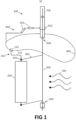
- FIG 1 diagrammatically shows a turbine system 100 according to embodiments of the present invention.
- the turbine system 100 comprises a turbine blade 200 which is coupled to a rotor shaft 300 by means of connecting rods 400.
- the rotor shaft 300 may be oriented horizontally, vertically or at an angle in-between relative to the ground and/or water surface, but preferably stands perpendicularly to the dominant flow direction of the flowing medium 500 (e.g. water).
- the rotor shaft 300 is rotatable thanks to bearings 600 of the turbine system 100.
- the turbine system 100 may be configured to be fixed or floating relative to the fluid.
- the turbine blade 200 Under the influence of the flowing medium 500, the turbine blade 200 is set in motion and rotates (e.g. on a circular path) around an axis which typically coincides with a theoretical centre line of the rotor shaft 300.
- the connecting rods 400 transfer the resulting generated torque of the turbine blade 200 to the rotor shaft 300, causing this to co-rotate.
- An energy converter 700 connected to the rotor shaft 300 converts the mechanical energy of the rotor shaft 300 and turbine blade 200 into another usable energy form (e.g. electricity).
- the connecting rods 400 are connected to the turbine blade 200 by means of rotational elements 410 (e.g. ball joints or hinges).
- rotational elements 410 e.g. ball joints or hinges.
- the turbine system 100 also contains a guide strip 800, and the turbine blade 200 is coupled to the guide strip 800 by means of a follower element 210.
- Figure 1 shows the follower element 210 as a ring 211 around the guide strip 800 at the end of a tiller 212.
- the guide strip 800 determines the orientation of the turbine blade 200: because the follower element 210 necessarily traces the guide strip 800, the variable angle of the turbine blade 200 is set by the tiller 212 at each point on the revolution.
- the guide strip 800 is here formed such that, because of the set orientation of the turbine blade 200, a higher energy yield for the turbine system 100 is obtained.
- the guide strip 800 may be firmly fixed (not shown) inside the turbine system 100 or may be positioned variably relative to the turbine system 100, e.g. via means of rotation 901 and/or translation 902.
- the variable positioning allows this to be adapted as a function of the flow conditions (e.g. flow direction and flow speed).
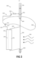
- Example 2 Turbine system with guide strip in which a segment of the turbine blade is controlled
- the turbine system 100 comprises a turbine blade 200 which is coupled to a rotor shaft 300 by means of connecting rods 400.
- the rotor shaft 300 may be oriented horizontally, vertically or at an angle in-between relative to the ground and/or water surface, but preferably stands perpendicularly to the dominant flow direction of the flowing medium 500 (e.g. water).
- the rotor shaft 300 is rotatable thanks to bearings 600 of the turbine system 100.
- the turbine system 100 may be configured to be fixed or floating relative to the fluid.
- the turbine blade 200 Under the influence of the flowing medium 500, the turbine blade 200 is set in motion and rotates (e.g. on a circular path) around an axis which typically coincides with a theoretical centre line of the rotor shaft 300.
- the connecting rods 400 transfer the resulting torque of the turbine blade 200 to the rotor shaft 300, causing this to co-rotate.
- An energy converter 700 connected to the rotor shaft 300 converts the mechanical energy of the rotor shaft 300 and turbine blade 200 into another usable energy form (e.g. electricity).
- the turbine blade 200 is divided into a first segment 201 and a second segment 202, which are connected together by means of one or more rotational elements (e.g. hinge or ball joint).
- the orientation of the second segment 202 is variable relative to the first segment 201, in the form of a variable angle between the two.
- the connecting rods 400 are here fixedly connected to the first segment 201 so that the orientation of the first segment 201 relative to the co-rotating rotor shaft 300 is here fixed.
- the turbine system 100 also comprises a guide strip 800, and the second turbine blade segment 202 is coupled to the guide strip 800 by means of a follower element 210.
- Figure 2 shows the follower element 210 as a ring 211 around the guide strip 800 at the end of a tiller 212.
- the guide strip 800 determines the orientation of the second turbine segment 202: because the follower element 210 necessarily traces the guide strip 800, the variable angle of the second turbine segment 202 is set by the tiller 212 at each point on the revolution.
- the guide strip 800 is here formed such that, because of the set orientation of the second turbine segment 202, a higher energy yield for the turbine system 100 is obtained.
- the guide strip 800 may be firmly fixed (not shown) inside the turbine system 100 or may be positioned variably 900 relative to the turbine system 100, e.g. via means of rotation 901 and/or translation 902.
- the variable positioning 211 allows this to be adapted as a function of the flow conditions (e.g. flow direction and flow speed).
- the connecting rods 400 are firmly attached to the first turbine blade segment 201 and the orientation thereof relative to the co-rotating rotor shaft 300 is thus fixed.
- the connecting rods 400 may also be connected by means of rotational elements 410 as described in example 1, so that the orientation of the first segment 201 is also variable.
- the orientation (e.g. angle) of the first segment may then be set separately relative to the second segment.
Landscapes
- Engineering & Computer Science (AREA)
- Life Sciences & Earth Sciences (AREA)
- Sustainable Development (AREA)
- Sustainable Energy (AREA)
- Chemical & Material Sciences (AREA)
- Combustion & Propulsion (AREA)
- Mechanical Engineering (AREA)
- General Engineering & Computer Science (AREA)
- Hydraulic Turbines (AREA)
- Other Liquid Machine Or Engine Such As Wave Power Use (AREA)
Claims (12)
- Turbinensystem (100) zum Erzeugen von Energie aus einem strömenden Fluid (500), das Wasser ist, wobei das Turbinensystem Folgendes umfasst:- eine Rotorwelle (300);- mindestens eine Turbinenblatt (200), die an die Rotorwelle (300) gekoppelt ist, wobei eine Ausrichtung mindestens eines Abschnitts der Turbinenblatt (200) relativ zu der Rotorwelle (300) variabel ist; und- einen Führungsstreifen (800), der an den Turbinenblattabschnitt gekoppelt ist, wobei der Führungsstreifen (800) die Ausrichtung des Turbinenblattabschnitts relativ zu der Rotorwelle (300) bestimmt, wobei der Turbinenblattabschnitt mit einem Nachläuferelement (210) zum Verfolgen des Führungsstreifens verbunden ist, wobei das Nachläuferelement eine Walze oder einen Gleitschuh umfasst,wobei der Führungsstreifen (800) ein glattes Profil, ohne Knick in dem Profil, aufweist.
- Turbinensystem (100) nach Anspruch 1, wobei die Rotorwelle (300) senkrecht zu einer Strömungsrichtung des Fluids (500) steht.
- Turbinensystem (100) nach einem der vorstehenden Ansprüche, das ein Turbinensystem vom Darrieus-Typ ist.
- Turbinensystem (100) nach einem der vorstehenden Ansprüche, wobei der Turbinenblattabschnitt die gesamte Turbinenblatt (200) ist oder wobei der Turbinenblattabschnitt nur ein Teil (202) der gesamten Turbinenblatt (200) ist oder
wobei der Turbinenblattabschnitt nur ein Teil (202) der gesamten Turbinenblatt (200) ist und wobei eine Kopplung zwischen dem Turbinenblattabschnitt (202) und dem Rest der Turbinenblatt (200) ein Drehelement (203) umfasst. - Turbinensystem (100) nach einem der vorstehenden Ansprüche, wobei eine Kopplung zwischen der Turbinenblatt (200) und der Rotorwelle (300) ein Drehelement (410) umfasst.
- Turbinensystem (100) nach einem der vorstehenden Ansprüche, wobei der Führungsstreifen (800) so gebildet ist, dass in Betrieb die Ausrichtung des Turbinenblattabschnitts (202) relativ zu der Rotorwelle (300) entlang einer Umdrehung der Turbinenblatt (200) variiert.
- Turbinensystem (100) nach Anspruch 6, wobei der Führungsstreifen (800) als nicht kreisförmige Schleife gebildet ist.
- Turbinensystem (100) nach dem vorstehenden Anspruch, wobei das Nachläuferelement (210) ein oder mehrere Führungsräder ist und wobei der Führungsstreifen eine Schiene ist.
- Turbinensystem (100) nach Anspruch 1, wobei das Nachläuferelement (210) einen Gleitschuh, einen Ring (211) oder einen Stift umfasst und/oder wobei der Führungsstreifen (800) einen Schlitz oder eine aufrechte Rippe zum Führen des Nachläuferelements (210) umfasst.
- Turbinensystem (100) nach einem der vorstehenden Ansprüche, wobei eine relative Position des Führungsstreifens (800) im Inneren des Turbinensystems (100) fixiert ist.
- Turbinensystem (100) nach einem von Anspruch 1 oder 10, weiter umfassend Mittel zur relativen Verschiebung (902) und/oder Drehung (901) des Führungsstreifens (800) im Inneren des Turbinensystems (100).
- Verwendung eines Führungsstreifens (800) in einem Turbinensystem (100) zum Ausrichten mindestens eines Abschnitts einer Turbinenblatt (200), der an den Führungsstreifen (800) gekoppelt ist, wobei das Turbinensystem Folgendes umfasst:- eine Rotorwelle (300);- mindestens eine Turbinenblatt (200), die an die Rotorwelle (300) gekoppelt ist, wobei eine Ausrichtung mindestens eines Abschnitts der Turbinenblatt (200) relativ zu der Rotorwelle (300) variabel ist; wobeider Führungsstreifen (800) an den Turbinenblattabschnitt gekoppelt ist, wobei der Führungsstreifen (800) die Ausrichtung des Turbinenblattabschnitts relativ zu der Rotorwelle (300) bestimmt, wobei der Turbinenblattabschnitt mit einem Nachläuferelement (210) zum Verfolgen des Führungsstreifens verbunden ist, wobei das Nachläuferelement eine Walze oder einen Gleitschuh umfasst, undwobei der Führungsstreifen (800) ein glattes Profil, ohne Knick in dem Profil, aufweist.
Applications Claiming Priority (1)
| Application Number | Priority Date | Filing Date | Title |
|---|---|---|---|
| BE20195252A BE1027193B1 (nl) | 2019-04-16 | 2019-04-16 | Turbinesysteem met leidband |
Publications (3)
| Publication Number | Publication Date |
|---|---|
| EP3726050A1 EP3726050A1 (de) | 2020-10-21 |
| EP3726050C0 EP3726050C0 (de) | 2024-08-21 |
| EP3726050B1 true EP3726050B1 (de) | 2024-08-21 |
Family
ID=66323608
Family Applications (1)
| Application Number | Title | Priority Date | Filing Date |
|---|---|---|---|
| EP20169990.7A Active EP3726050B1 (de) | 2019-04-16 | 2020-04-16 | Turbinensystem mit führungsleiste |
Country Status (2)
| Country | Link |
|---|---|
| EP (1) | EP3726050B1 (de) |
| BE (1) | BE1027193B1 (de) |
Cited By (1)
| Publication number | Priority date | Publication date | Assignee | Title |
|---|---|---|---|---|
| US12416283B2 (en) | 2019-12-04 | 2025-09-16 | Michael Scot Cummings | Reactive, reversible blade turbine for power generation and pumping water |
Family Cites Families (8)
| Publication number | Priority date | Publication date | Assignee | Title |
|---|---|---|---|---|
| EA002751B1 (ru) | 1999-01-06 | 2002-08-29 | Вотер Пауэр Индастриз Ас | Турбина, приводимая в действие текучей средой |
| SE0004845L (sv) * | 2000-12-27 | 2002-06-28 | Winmill As | Vind- eller vattendriven anordning för generering av elektrisk ström, drivning av pumpar och liknande |
| FR2924180A1 (fr) * | 2007-11-23 | 2009-05-29 | Patrick Marie Etienne | Moteur eolien a pales verticales orientables. |
| CN101265880B (zh) * | 2008-04-30 | 2010-06-02 | 杨晶菁 | 基于叶片转角控制的可防暴风垂直轴风力机 |
| US20130017084A1 (en) * | 2011-07-13 | 2013-01-17 | Claude Anderson | High efficiency verical axis wind turbine |
| WO2015034096A1 (ja) | 2013-09-09 | 2015-03-12 | 株式会社New Act | 羽根構造体及び発電システム |
| KR101573758B1 (ko) * | 2014-01-27 | 2015-12-02 | 디에치이앤이(주) | 수직축 풍력발전 장치 |
| CN107829876A (zh) * | 2017-10-26 | 2018-03-23 | 中国石油大学(华东) | 一种用于垂直轴风力发电装置的叶片倾角优化方法 |
-
2019
- 2019-04-16 BE BE20195252A patent/BE1027193B1/nl not_active IP Right Cessation
-
2020
- 2020-04-16 EP EP20169990.7A patent/EP3726050B1/de active Active
Cited By (1)
| Publication number | Priority date | Publication date | Assignee | Title |
|---|---|---|---|---|
| US12416283B2 (en) | 2019-12-04 | 2025-09-16 | Michael Scot Cummings | Reactive, reversible blade turbine for power generation and pumping water |
Also Published As
| Publication number | Publication date |
|---|---|
| EP3726050A1 (de) | 2020-10-21 |
| EP3726050C0 (de) | 2024-08-21 |
| BE1027193B1 (nl) | 2020-11-17 |
| BE1027193A1 (nl) | 2020-11-10 |
Similar Documents
| Publication | Publication Date | Title |
|---|---|---|
| CN100494672C (zh) | 利用扩散器从流动的流体中提取能量的方法和装置 | |
| US8664790B2 (en) | Underwater power generator with dual blade sets | |
| US10218246B2 (en) | Variable diameter and angle vertical axis turbine | |
| KR20090045225A (ko) | 수력발전장치 | |
| GB2360551A (en) | Turbine | |
| KR20140014201A (ko) | 물의 흐름에서 에너지를 얻기 위한 발전소 및 이의 작동 방법 | |
| EP3726050B1 (de) | Turbinensystem mit führungsleiste | |
| EP1960659B1 (de) | Gezeitenstromumwandlungssystem | |
| US4209281A (en) | Wind driven prime mover | |
| CN102713259A (zh) | 波浪流装置及其方法 | |
| JP2010520414A (ja) | ハブレス風車 | |
| US20220034291A1 (en) | Systems and methods for generating electrical energy | |
| MXPA06013979A (es) | Un sistema de generacion de energia subacuatica. | |
| EP4662402A1 (de) | Turbine mit beweglichen schaufeln mit flachem fluss | |
| RU2141059C1 (ru) | Крыло (лопасть) с самоустановкой угла атаки к направлению набегающего потока среды | |
| US11879423B2 (en) | Self-regulating water turbine runner, water turbine equipped with sub-runner located upstream of the main runner and water turbine comprising the same | |
| RU2044920C1 (ru) | Ветродвигатель | |
| US20240229765A1 (en) | Wind turbine | |
| WO2010012029A1 (en) | Power generator | |
| US7425773B1 (en) | Wave-powered generator | |
| GB2512110B (en) | A wave energy conversion system | |
| GB2373028A (en) | Turbines | |
| AU2013200454A1 (en) | Submerged waterwheel for oceanic power | |
| KR20200022311A (ko) | 흐르는 유체로부터 에너지를 획득하는 장치 및 방법 | |
| FR3041389A1 (fr) | Procede de pilotage d'au moins une paire d'eoliennes a axe vertical supportees par une meme structure de support et ensemble de production d'energie correspondant |
Legal Events
| Date | Code | Title | Description |
|---|---|---|---|
| PUAI | Public reference made under article 153(3) epc to a published international application that has entered the european phase |
Free format text: ORIGINAL CODE: 0009012 |
|
| STAA | Information on the status of an ep patent application or granted ep patent |
Free format text: STATUS: THE APPLICATION HAS BEEN PUBLISHED |
|
| AK | Designated contracting states |
Kind code of ref document: A1 Designated state(s): AL AT BE BG CH CY CZ DE DK EE ES FI FR GB GR HR HU IE IS IT LI LT LU LV MC MK MT NL NO PL PT RO RS SE SI SK SM TR |
|
| AX | Request for extension of the european patent |
Extension state: BA ME |
|
| STAA | Information on the status of an ep patent application or granted ep patent |
Free format text: STATUS: REQUEST FOR EXAMINATION WAS MADE |
|
| 17P | Request for examination filed |
Effective date: 20201023 |
|
| RAV | Requested validation state of the european patent: fee paid |
Extension state: KH Effective date: 20201023 |
|
| RAX | Requested extension states of the european patent have changed |
Extension state: BA Payment date: 20201023 Extension state: ME |
|
| RBV | Designated contracting states (corrected) |
Designated state(s): AL AT BE BG CH CY CZ DE DK EE ES FI FR GB GR HR HU IE IS IT LI LT LU LV MC MK MT NL NO PL PT RO RS SE SI SK SM TR |
|
| STAA | Information on the status of an ep patent application or granted ep patent |
Free format text: STATUS: EXAMINATION IS IN PROGRESS |
|
| 17Q | First examination report despatched |
Effective date: 20220705 |
|
| GRAP | Despatch of communication of intention to grant a patent |
Free format text: ORIGINAL CODE: EPIDOSNIGR1 |
|
| STAA | Information on the status of an ep patent application or granted ep patent |
Free format text: STATUS: GRANT OF PATENT IS INTENDED |
|
| INTG | Intention to grant announced |
Effective date: 20231122 |
|
| RIN1 | Information on inventor provided before grant (corrected) |
Inventor name: RIJKE, REINIER JOHANNES |
|
| GRAJ | Information related to disapproval of communication of intention to grant by the applicant or resumption of examination proceedings by the epo deleted |
Free format text: ORIGINAL CODE: EPIDOSDIGR1 |
|
| STAA | Information on the status of an ep patent application or granted ep patent |
Free format text: STATUS: EXAMINATION IS IN PROGRESS |
|
| INTC | Intention to grant announced (deleted) | ||
| GRAP | Despatch of communication of intention to grant a patent |
Free format text: ORIGINAL CODE: EPIDOSNIGR1 |
|
| STAA | Information on the status of an ep patent application or granted ep patent |
Free format text: STATUS: GRANT OF PATENT IS INTENDED |
|
| INTG | Intention to grant announced |
Effective date: 20240516 |
|
| GRAS | Grant fee paid |
Free format text: ORIGINAL CODE: EPIDOSNIGR3 |
|
| GRAA | (expected) grant |
Free format text: ORIGINAL CODE: 0009210 |
|
| STAA | Information on the status of an ep patent application or granted ep patent |
Free format text: STATUS: THE PATENT HAS BEEN GRANTED |
|
| AK | Designated contracting states |
Kind code of ref document: B1 Designated state(s): AL AT BE BG CH CY CZ DE DK EE ES FI FR GB GR HR HU IE IS IT LI LT LU LV MC MK MT NL NO PL PT RO RS SE SI SK SM TR |
|
| REG | Reference to a national code |
Ref country code: GB Ref legal event code: FG4D |
|
| REG | Reference to a national code |
Ref country code: CH Ref legal event code: EP |
|
| REG | Reference to a national code |
Ref country code: IE Ref legal event code: FG4D |
|
| REG | Reference to a national code |
Ref country code: DE Ref legal event code: R096 Ref document number: 602020036048 Country of ref document: DE |
|
| U01 | Request for unitary effect filed |
Effective date: 20240904 |
|
| U07 | Unitary effect registered |
Designated state(s): AT BE BG DE DK EE FI FR IT LT LU LV MT NL PT RO SE SI Effective date: 20241011 |
|
| PG25 | Lapsed in a contracting state [announced via postgrant information from national office to epo] |
Ref country code: NO Free format text: LAPSE BECAUSE OF FAILURE TO SUBMIT A TRANSLATION OF THE DESCRIPTION OR TO PAY THE FEE WITHIN THE PRESCRIBED TIME-LIMIT Effective date: 20241121 |
|
| PG25 | Lapsed in a contracting state [announced via postgrant information from national office to epo] |
Ref country code: PL Free format text: LAPSE BECAUSE OF FAILURE TO SUBMIT A TRANSLATION OF THE DESCRIPTION OR TO PAY THE FEE WITHIN THE PRESCRIBED TIME-LIMIT Effective date: 20240821 Ref country code: GR Free format text: LAPSE BECAUSE OF FAILURE TO SUBMIT A TRANSLATION OF THE DESCRIPTION OR TO PAY THE FEE WITHIN THE PRESCRIBED TIME-LIMIT Effective date: 20241122 |
|
| PG25 | Lapsed in a contracting state [announced via postgrant information from national office to epo] |
Ref country code: IS Free format text: LAPSE BECAUSE OF FAILURE TO SUBMIT A TRANSLATION OF THE DESCRIPTION OR TO PAY THE FEE WITHIN THE PRESCRIBED TIME-LIMIT Effective date: 20241221 |
|
| PG25 | Lapsed in a contracting state [announced via postgrant information from national office to epo] |
Ref country code: HR Free format text: LAPSE BECAUSE OF FAILURE TO SUBMIT A TRANSLATION OF THE DESCRIPTION OR TO PAY THE FEE WITHIN THE PRESCRIBED TIME-LIMIT Effective date: 20240821 |
|
| PG25 | Lapsed in a contracting state [announced via postgrant information from national office to epo] |
Ref country code: RS Free format text: LAPSE BECAUSE OF FAILURE TO SUBMIT A TRANSLATION OF THE DESCRIPTION OR TO PAY THE FEE WITHIN THE PRESCRIBED TIME-LIMIT Effective date: 20241121 Ref country code: ES Free format text: LAPSE BECAUSE OF FAILURE TO SUBMIT A TRANSLATION OF THE DESCRIPTION OR TO PAY THE FEE WITHIN THE PRESCRIBED TIME-LIMIT Effective date: 20240821 |
|
| PG25 | Lapsed in a contracting state [announced via postgrant information from national office to epo] |
Ref country code: RS Free format text: LAPSE BECAUSE OF FAILURE TO SUBMIT A TRANSLATION OF THE DESCRIPTION OR TO PAY THE FEE WITHIN THE PRESCRIBED TIME-LIMIT Effective date: 20241121 Ref country code: PL Free format text: LAPSE BECAUSE OF FAILURE TO SUBMIT A TRANSLATION OF THE DESCRIPTION OR TO PAY THE FEE WITHIN THE PRESCRIBED TIME-LIMIT Effective date: 20240821 Ref country code: NO Free format text: LAPSE BECAUSE OF FAILURE TO SUBMIT A TRANSLATION OF THE DESCRIPTION OR TO PAY THE FEE WITHIN THE PRESCRIBED TIME-LIMIT Effective date: 20241121 Ref country code: IS Free format text: LAPSE BECAUSE OF FAILURE TO SUBMIT A TRANSLATION OF THE DESCRIPTION OR TO PAY THE FEE WITHIN THE PRESCRIBED TIME-LIMIT Effective date: 20241221 Ref country code: HR Free format text: LAPSE BECAUSE OF FAILURE TO SUBMIT A TRANSLATION OF THE DESCRIPTION OR TO PAY THE FEE WITHIN THE PRESCRIBED TIME-LIMIT Effective date: 20240821 Ref country code: GR Free format text: LAPSE BECAUSE OF FAILURE TO SUBMIT A TRANSLATION OF THE DESCRIPTION OR TO PAY THE FEE WITHIN THE PRESCRIBED TIME-LIMIT Effective date: 20241122 Ref country code: ES Free format text: LAPSE BECAUSE OF FAILURE TO SUBMIT A TRANSLATION OF THE DESCRIPTION OR TO PAY THE FEE WITHIN THE PRESCRIBED TIME-LIMIT Effective date: 20240821 |
|
| PG25 | Lapsed in a contracting state [announced via postgrant information from national office to epo] |
Ref country code: SM Free format text: LAPSE BECAUSE OF FAILURE TO SUBMIT A TRANSLATION OF THE DESCRIPTION OR TO PAY THE FEE WITHIN THE PRESCRIBED TIME-LIMIT Effective date: 20240821 |
|
| PG25 | Lapsed in a contracting state [announced via postgrant information from national office to epo] |
Ref country code: CZ Free format text: LAPSE BECAUSE OF FAILURE TO SUBMIT A TRANSLATION OF THE DESCRIPTION OR TO PAY THE FEE WITHIN THE PRESCRIBED TIME-LIMIT Effective date: 20240821 |
|
| PG25 | Lapsed in a contracting state [announced via postgrant information from national office to epo] |
Ref country code: SK Free format text: LAPSE BECAUSE OF FAILURE TO SUBMIT A TRANSLATION OF THE DESCRIPTION OR TO PAY THE FEE WITHIN THE PRESCRIBED TIME-LIMIT Effective date: 20240821 |
|
| U20 | Renewal fee for the european patent with unitary effect paid |
Year of fee payment: 6 Effective date: 20250425 |
|
| PLBE | No opposition filed within time limit |
Free format text: ORIGINAL CODE: 0009261 |
|
| STAA | Information on the status of an ep patent application or granted ep patent |
Free format text: STATUS: NO OPPOSITION FILED WITHIN TIME LIMIT |
|
| PGFP | Annual fee paid to national office [announced via postgrant information from national office to epo] |
Ref country code: IE Payment date: 20250627 Year of fee payment: 6 |
|
| 26N | No opposition filed |
Effective date: 20250522 |
|
| REG | Reference to a national code |
Ref country code: CH Ref legal event code: H13 Free format text: ST27 STATUS EVENT CODE: U-0-0-H10-H13 (AS PROVIDED BY THE NATIONAL OFFICE) Effective date: 20251125 |
|
| PG25 | Lapsed in a contracting state [announced via postgrant information from national office to epo] |
Ref country code: MC Free format text: LAPSE BECAUSE OF FAILURE TO SUBMIT A TRANSLATION OF THE DESCRIPTION OR TO PAY THE FEE WITHIN THE PRESCRIBED TIME-LIMIT Effective date: 20240821 |
|
| PG25 | Lapsed in a contracting state [announced via postgrant information from national office to epo] |
Ref country code: CH Free format text: LAPSE BECAUSE OF NON-PAYMENT OF DUE FEES Effective date: 20250430 |
|
| PGFP | Annual fee paid to national office [announced via postgrant information from national office to epo] |
Ref country code: GB Payment date: 20260324 Year of fee payment: 7 |