EP3726048B1 - An auto-stop start system for a vehicle - Google Patents
An auto-stop start system for a vehicle Download PDFInfo
- Publication number
- EP3726048B1 EP3726048B1 EP19169216.9A EP19169216A EP3726048B1 EP 3726048 B1 EP3726048 B1 EP 3726048B1 EP 19169216 A EP19169216 A EP 19169216A EP 3726048 B1 EP3726048 B1 EP 3726048B1
- Authority
- EP
- European Patent Office
- Prior art keywords
- auto
- stop start
- vehicle
- control device
- start function
- Prior art date
- Legal status (The legal status is an assumption and is not a legal conclusion. Google has not performed a legal analysis and makes no representation as to the accuracy of the status listed.)
- Active
Links
Images

Classifications
-
- F—MECHANICAL ENGINEERING; LIGHTING; HEATING; WEAPONS; BLASTING
- F02—COMBUSTION ENGINES; HOT-GAS OR COMBUSTION-PRODUCT ENGINE PLANTS
- F02N—STARTING OF COMBUSTION ENGINES; STARTING AIDS FOR SUCH ENGINES, NOT OTHERWISE PROVIDED FOR
- F02N11/00—Starting of engines by means of electric motors
- F02N11/08—Circuits specially adapted for starting of engines
- F02N11/0803—Circuits specially adapted for starting of engines characterised by means for initiating engine start or stop
-
- F—MECHANICAL ENGINEERING; LIGHTING; HEATING; WEAPONS; BLASTING
- F02—COMBUSTION ENGINES; HOT-GAS OR COMBUSTION-PRODUCT ENGINE PLANTS
- F02N—STARTING OF COMBUSTION ENGINES; STARTING AIDS FOR SUCH ENGINES, NOT OTHERWISE PROVIDED FOR
- F02N11/00—Starting of engines by means of electric motors
- F02N11/08—Circuits specially adapted for starting of engines
- F02N11/0814—Circuits specially adapted for starting of engines comprising means for controlling automatic idle-start-stop
- F02N11/0818—Conditions for starting or stopping the engine or for deactivating the idle-start-stop mode
- F02N11/0822—Conditions for starting or stopping the engine or for deactivating the idle-start-stop mode related to action of the driver
-
- F—MECHANICAL ENGINEERING; LIGHTING; HEATING; WEAPONS; BLASTING
- F02—COMBUSTION ENGINES; HOT-GAS OR COMBUSTION-PRODUCT ENGINE PLANTS
- F02N—STARTING OF COMBUSTION ENGINES; STARTING AIDS FOR SUCH ENGINES, NOT OTHERWISE PROVIDED FOR
- F02N11/00—Starting of engines by means of electric motors
- F02N11/08—Circuits specially adapted for starting of engines
- F02N11/0814—Circuits specially adapted for starting of engines comprising means for controlling automatic idle-start-stop
- F02N11/0818—Conditions for starting or stopping the engine or for deactivating the idle-start-stop mode
- F02N11/0833—Vehicle conditions
-
- F—MECHANICAL ENGINEERING; LIGHTING; HEATING; WEAPONS; BLASTING
- F02—COMBUSTION ENGINES; HOT-GAS OR COMBUSTION-PRODUCT ENGINE PLANTS
- F02N—STARTING OF COMBUSTION ENGINES; STARTING AIDS FOR SUCH ENGINES, NOT OTHERWISE PROVIDED FOR
- F02N11/00—Starting of engines by means of electric motors
- F02N11/08—Circuits specially adapted for starting of engines
- F02N11/0814—Circuits specially adapted for starting of engines comprising means for controlling automatic idle-start-stop
- F02N11/0844—Circuits specially adapted for starting of engines comprising means for controlling automatic idle-start-stop with means for restarting the engine directly after an engine stop request, e.g. caused by change of driver mind
-
- F—MECHANICAL ENGINEERING; LIGHTING; HEATING; WEAPONS; BLASTING
- F02—COMBUSTION ENGINES; HOT-GAS OR COMBUSTION-PRODUCT ENGINE PLANTS
- F02N—STARTING OF COMBUSTION ENGINES; STARTING AIDS FOR SUCH ENGINES, NOT OTHERWISE PROVIDED FOR
- F02N2200/00—Parameters used for control of starting apparatus
- F02N2200/10—Parameters used for control of starting apparatus said parameters being related to driver demands or status
-
- F—MECHANICAL ENGINEERING; LIGHTING; HEATING; WEAPONS; BLASTING
- F02—COMBUSTION ENGINES; HOT-GAS OR COMBUSTION-PRODUCT ENGINE PLANTS
- F02N—STARTING OF COMBUSTION ENGINES; STARTING AIDS FOR SUCH ENGINES, NOT OTHERWISE PROVIDED FOR
- F02N2200/00—Parameters used for control of starting apparatus
- F02N2200/12—Parameters used for control of starting apparatus said parameters being related to the vehicle exterior
- F02N2200/123—Information about vehicle position, e.g. from navigation systems or GPS signals
-
- F—MECHANICAL ENGINEERING; LIGHTING; HEATING; WEAPONS; BLASTING
- F02—COMBUSTION ENGINES; HOT-GAS OR COMBUSTION-PRODUCT ENGINE PLANTS
- F02N—STARTING OF COMBUSTION ENGINES; STARTING AIDS FOR SUCH ENGINES, NOT OTHERWISE PROVIDED FOR
- F02N2300/00—Control related aspects of engine starting
- F02N2300/20—Control related aspects of engine starting characterised by the control method
-
- Y—GENERAL TAGGING OF NEW TECHNOLOGICAL DEVELOPMENTS; GENERAL TAGGING OF CROSS-SECTIONAL TECHNOLOGIES SPANNING OVER SEVERAL SECTIONS OF THE IPC; TECHNICAL SUBJECTS COVERED BY FORMER USPC CROSS-REFERENCE ART COLLECTIONS [XRACs] AND DIGESTS
- Y02—TECHNOLOGIES OR APPLICATIONS FOR MITIGATION OR ADAPTATION AGAINST CLIMATE CHANGE
- Y02T—CLIMATE CHANGE MITIGATION TECHNOLOGIES RELATED TO TRANSPORTATION
- Y02T10/00—Road transport of goods or passengers
- Y02T10/10—Internal combustion engine [ICE] based vehicles
- Y02T10/40—Engine management systems
Definitions
- the invention relates to an auto-stop start system for a vehicle and method for controlling an auto-stop start system of a vehicle.
- An auto-stop start system of a vehicle is often used for reducing fuel consumption and emissions from an internal combustion engine by reducing the time the engine is idling.
- the system will automatically stop and start the engine provided that some predetermined conditions are fulfilled.
- the engine is stopped when it is predicted that the vehicle will be stationary for a longer amount of time. For example, the engine is stopped when the vehicle is waiting at traffic lights or when the vehicle frequently comes to a stop in traffic jams.
- Document DE102008060350A1 relates to a method for automatic shutdown of an ICE in a vehicle, by means of a stop-start unit.
- a stop-start unit When the vehicle has been decelerated to a standstill, if the driver depresses the brake pedal fully within a predetermined interval of time and then releases the brake again, an automatic shutdown is prevented.
- Document JP2012127315 relates to a control device for an idle stop that automatically stops an engine during idling.
- the idle stop function is prohibited, and after the lapse of a predetermined prohibition period, the idle stop function is automatically returned to an operable state.
- An objective of the invention is to provide an auto-stop start system for a vehicle, where the use of the system can be improved.
- the invention is based on the insight that by such an auto-stop start system, the operator or driver is able to pause the auto-stop start function without turning off the auto-stop start function when the auto-stop start function would be inconvenient or inappropriate to use due to the traffic conditions.
- an automatic reactivation of the auto-stop start function by means of the control unit the risk of non-use of the function later on due to the driver is forgetting to reactivate the function is eliminated.
- the operator is able to select the duration of the temporary deactivation of the auto-stop start function, the auto-stop start function can be paused in a way adapted to the current traffic conditions.
- an operator of the vehicle can be more prone to not turning off the auto-stop start function.
- the auto stop-start system can be used efficiently when a driver knows the traffic loads. For example, when the distance of a traffic merge jam is known while the time spent in this traffic merge jam is unknown, a travelled distance-based reactivation of the auto-stop start function can be beneficial.
- the distance can be selectable within an interval from 50 meters to 1000 meters, preferably 100 to 500 meters.
- the predetermined duration of the temporary deactivation is set by one or more output signals from the control device and thereby the operator has the opportunity to adjust the predetermined duration of the temporary deactivation by manoeuvring the control device.
- the operator can use multiples of a default value or choose a value within an interval.
- the predetermined duration of the temporary deactivation is stepwise increasable by means of the control device.
- the duration of the temporary deactivation state may be adjusted by the operator to suit the predicted approaching traffic situation.
- the auto-stop start function can be turned off and on by means of the control device, and, preferably the temporary deactivation of the auto-stop start function is selectable by holding the control device, such as pressing a button, for a predetermined time period in a position for which the auto-stop start function is turned off.
- the control device such as pressing a button
- multiple presses of a button can be used for changing between an active auto-stop start function and a temporary deactivation of the auto-stop start function, and holding the button pressed for a predetermined time period may allow the auto-stop start function to be disabled.
- a further objective is to provide a method for controlling an auto-stop start system of a vehicle, by which method the use of the system can be improved.
- the invention relates to a vehicle comprising an auto-stop start system according to the invention.
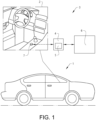
- Fig. 1 shows a vehicle 1, an enlarged part 2 of the interior of the vehicle 1 and a schematic view of an auto-stop start system 3.
- the auto-stop start system 3 has a control unit 4 with an auto-stop start function 5 controlling stop and start of an engine 6 of the vehicle 1.
- the auto-stop start function 5 is used for automatically stop and start the engine 6 provided that some predetermined conditions are fulfilled, for reducing the time the engine 6 is idling.
- the auto-stop start system 3 further comprises a control device 7 arranged in the vehicle 1 by which control device 7 the auto-stop start function 5 can be temporarily deactivated by an operator of the vehicle 1.
- control device 7 When the auto-stop start function 5 is deactivated no automatic stop or start of the vehicle 1 is performed by the control unit 4.
- the control unit 4 is configured to reactivate the auto-stop start function 5 after a predetermined duration of a temporary deactivation. Thereafter, the engine 6 is again automatically stopped and started according to the predetermined conditions.
- the predetermined duration of the temporary deactivation of the auto-stop start function 5 is selectable by means of the control device 7.
- control device 7 can be a button to be pressed for temporarily deactivate the auto-stop start function 5.
- the predetermined duration of the temporary deactivation selected and/or the remaining part of the temporary deactivation duration can be shown on a display.
- control device 7 can also be arranged for turning off and on the auto-stop start system 3 or auto-stop start function 5.
- the temporary deactivation of the auto-stop start function 5 can be selectable by holding the control device 7 for a predetermined time period in a position for which the auto-stop start function 5 is turned off.
- a short press of the button 7 will turn off the auto-stop start function 5 while pressing the button 7 longer will instead deactivate the auto-stop start function 5.
- the predetermined duration of the temporary deactivation can be stepwise increased by means of the control device, by repeatedly pressing the button 7 for instance.
- buttons 7 can be used for changing between an active auto-stop start function and a temporary deactivation of the auto-stop start function 5, and holding the button 7 pressed for a predetermined time period may allow the auto-stop start function 5 to be disabled.
- control device could instead be integrated in a touch screen where the predetermined duration of the temporary deactivation can be selected and seen on the display device.
- the control unit 4 is configured to reactivate the auto-stop start function 5 after a predetermined distance travelled by the vehicle 1 which distance is selectable by means of the control device 7.
- Fig. 2 shows a flow chart illustrating one example embodiment of a method for controlling an auto-stop start system 3 of a vehicle 1.
- Fig. 1 shows a flow chart illustrating one example embodiment of a method for controlling an auto-stop start system 3 of a vehicle 1.
- the components used for performing the method reference is also made to the description hereinabove and Fig. 1 .
- the method comprises the step of receiving 100 a request signal from a control device 7 manoeuvrable by an operator of the vehicle 1, for deactivating an auto-stop start function 5 of the auto-stop start system and selecting a predetermined duration of a temporary deactivation of the auto-stop start function 5.
- the method further comprises the step of temporarily deactivating 200 the auto-stop start function 5 of the auto-stop start system 3. Such deactivation can optionally be subject to further conditions. Thereafter, the method comprises the step of checking 300 if the predetermined duration of the temporary deactivation has passed. Provided that the predetermined duration is identified to have been passed, i.e. if "YES" in Fig. 2 , the method comprises the step of reactivating 400 the auto-stop start function 5 by a control unit 4 after the predetermined duration of the temporary deactivation. Such reactivation can optionally be subject to other conditions. Otherwise, i.e. if "NO" in Fig. 2 , the auto-stop start function 5 is maintained in the deactivated state.
- the method comprises the step of reactivating the auto-stop start function after a predetermined distance travelled by the vehicle which distance is selectable by means of the control device.
- the control unit 4 may comprise one or more microprocessors and/or one or more memory devices or any other components for executing computer programs to perform the method.
- the control unit 4 is preferably provided with a computer program comprising program code means for performing the steps of any example embodiment of the method described hereinabove.
- the control unit 4 can be a separate component or be integrated in another controller of the vehicle 1.
Landscapes
- Engineering & Computer Science (AREA)
- Chemical & Material Sciences (AREA)
- Combustion & Propulsion (AREA)
- Mechanical Engineering (AREA)
- General Engineering & Computer Science (AREA)
- Control Of Vehicle Engines Or Engines For Specific Uses (AREA)
Description
- The invention relates to an auto-stop start system for a vehicle and method for controlling an auto-stop start system of a vehicle.
- An auto-stop start system of a vehicle is often used for reducing fuel consumption and emissions from an internal combustion engine by reducing the time the engine is idling. The system will automatically stop and start the engine provided that some predetermined conditions are fulfilled. Typically, the engine is stopped when it is predicted that the vehicle will be stationary for a longer amount of time. For example, the engine is stopped when the vehicle is waiting at traffic lights or when the vehicle frequently comes to a stop in traffic jams.
- The effectiveness of such an auto-stop start system is however dependent on the traffic situation. The amount of time the vehicle actually remains stationary will have a great impact on the effectiveness of the system. Should the system stop and start to often, not only can the emissions increase, but it can cause annoyance to the driver due to a delayed power response when the driver requests acceleration. In addition, extensive stop and start repetitions will cause increased wear on several components, such as battery, starter motor and will have an impact on the lubrication of the engine.
- Document
DE102008060350A1 relates to a method for automatic shutdown of an ICE in a vehicle, by means of a stop-start unit. When the vehicle has been decelerated to a standstill, if the driver depresses the brake pedal fully within a predetermined interval of time and then releases the brake again, an automatic shutdown is prevented. - Document
JP2012127315 - An objective of the invention is to provide an auto-stop start system for a vehicle, where the use of the system can be improved.
- The objective is achieved by an auto-stop start system for a vehicle according to
claim 1. - The invention is based on the insight that by such an auto-stop start system, the operator or driver is able to pause the auto-stop start function without turning off the auto-stop start function when the auto-stop start function would be inconvenient or inappropriate to use due to the traffic conditions. By an automatic reactivation of the auto-stop start function by means of the control unit, the risk of non-use of the function later on due to the driver is forgetting to reactivate the function is eliminated. Since the operator is able to select the duration of the temporary deactivation of the auto-stop start function, the auto-stop start function can be paused in a way adapted to the current traffic conditions. By the invention, an operator of the vehicle can be more prone to not turning off the auto-stop start function. Hereby, the auto stop-start system can be used efficiently when a driver knows the traffic loads. For example, when the distance of a traffic merge jam is known while the time spent in this traffic merge jam is unknown, a travelled distance-based reactivation of the auto-stop start function can be beneficial. For example, the distance can be selectable within an interval from 50 meters to 1000 meters, preferably 100 to 500 meters.
- By "selectable by means of the control device" is meant that the predetermined duration of the temporary deactivation is set by one or more output signals from the control device and thereby the operator has the opportunity to adjust the predetermined duration of the temporary deactivation by manoeuvring the control device. For example, the operator can use multiples of a default value or choose a value within an interval.
- According to a further embodiment, the predetermined duration of the temporary deactivation is stepwise increasable by means of the control device. Hereby, the duration of the temporary deactivation state may be adjusted by the operator to suit the predicted approaching traffic situation.
- According to a further embodiment, the auto-stop start function can be turned off and on by means of the control device, and, preferably the temporary deactivation of the auto-stop start function is selectable by holding the control device, such as pressing a button, for a predetermined time period in a position for which the auto-stop start function is turned off. Hereby, the need for additional hardware can be eliminated and a user friendly control input can be provided for the operator.
- According to a further embodiment, multiple presses of a button can be used for changing between an active auto-stop start function and a temporary deactivation of the auto-stop start function, and holding the button pressed for a predetermined time period may allow the auto-stop start function to be disabled.
- According to another aspect of the invention, a further objective is to provide a method for controlling an auto-stop start system of a vehicle, by which method the use of the system can be improved.
- This objective is achieved by a method for controlling an auto-stop start system of a vehicle according to claim 9.
- In addition, the invention relates to a vehicle comprising an auto-stop start system according to the invention.
- The advantages of the method and the vehicle are similar to the advantages already discussed hereinabove with reference to the different embodiments of the auto-stop start system.
- Further advantages and advantageous features of the invention are disclosed in the following description and in the claims.
- With reference to the appended drawings, below follows a more detailed description of embodiments of the invention cited as examples.
- In the drawings:
-
Fig. 1 shows an auto-stop start system and a vehicle provided with the auto-stop start system, and -
Fig. 2 is a flow chart illustrating a method for controlling an auto-stop start system of a vehicle. -
Fig. 1 shows avehicle 1, an enlargedpart 2 of the interior of thevehicle 1 and a schematic view of an auto-stop start system 3. The auto-stop start system 3 has a control unit 4 with an auto-stop start function 5 controlling stop and start of anengine 6 of thevehicle 1. The auto-stop start function 5 is used for automatically stop and start theengine 6 provided that some predetermined conditions are fulfilled, for reducing the time theengine 6 is idling. - The auto-
stop start system 3 further comprises acontrol device 7 arranged in thevehicle 1 by whichcontrol device 7 the auto-stop start function 5 can be temporarily deactivated by an operator of thevehicle 1. When the auto-stop start function 5 is deactivated no automatic stop or start of thevehicle 1 is performed by the control unit 4. The control unit 4 is configured to reactivate the auto-stop start function 5 after a predetermined duration of a temporary deactivation. Thereafter, theengine 6 is again automatically stopped and started according to the predetermined conditions. The predetermined duration of the temporary deactivation of the auto-stop start function 5 is selectable by means of thecontrol device 7. - For example, the
control device 7 can be a button to be pressed for temporarily deactivate the auto-stop start function 5. The predetermined duration of the temporary deactivation selected and/or the remaining part of the temporary deactivation duration can be shown on a display. - Optionally, the
control device 7 can also be arranged for turning off and on the auto-stop start system 3 or auto-stop start function 5. For example, the temporary deactivation of the auto-stop start function 5 can be selectable by holding thecontrol device 7 for a predetermined time period in a position for which the auto-stop start function 5 is turned off. Thus, a short press of thebutton 7 will turn off the auto-stop start function 5 while pressing thebutton 7 longer will instead deactivate the auto-stop start function 5. - Optionally, the predetermined duration of the temporary deactivation can be stepwise increased by means of the control device, by repeatedly pressing the
button 7 for instance. - Alternatively, multiple presses of the
button 7 can be used for changing between an active auto-stop start function and a temporary deactivation of the auto-stop start function 5, and holding thebutton 7 pressed for a predetermined time period may allow the auto-stop start function 5 to be disabled. - In another embodiment, the control device could instead be integrated in a touch screen where the predetermined duration of the temporary deactivation can be selected and seen on the display device.
- The control unit 4 is configured to reactivate the auto-
stop start function 5 after a predetermined distance travelled by thevehicle 1 which distance is selectable by means of thecontrol device 7. -
Fig. 2 shows a flow chart illustrating one example embodiment of a method for controlling an auto-stop start system 3 of avehicle 1. As regards the components used for performing the method, reference is also made to the description hereinabove andFig. 1 . - The method comprises the step of receiving 100 a request signal from a
control device 7 manoeuvrable by an operator of thevehicle 1, for deactivating an auto-stop start function 5 of the auto-stop start system and selecting a predetermined duration of a temporary deactivation of the auto-stop start function 5. - The method further comprises the step of temporarily deactivating 200 the auto-
stop start function 5 of the auto-stop start system 3. Such deactivation can optionally be subject to further conditions. Thereafter, the method comprises the step of checking 300 if the predetermined duration of the temporary deactivation has passed. Provided that the predetermined duration is identified to have been passed, i.e. if "YES" inFig. 2 , the method comprises the step of reactivating 400 the auto-stop start function 5 by a control unit 4 after the predetermined duration of the temporary deactivation. Such reactivation can optionally be subject to other conditions. Otherwise, i.e. if "NO" inFig. 2 , the auto-stop start function 5 is maintained in the deactivated state. - The method comprises the step of reactivating the auto-stop start function after a predetermined distance travelled by the vehicle which distance is selectable by means of the control device.
- The control unit 4 may comprise one or more microprocessors and/or one or more memory devices or any other components for executing computer programs to perform the method. Thus, the control unit 4 is preferably provided with a computer program comprising program code means for performing the steps of any example embodiment of the method described hereinabove. The control unit 4 can be a separate component or be integrated in another controller of the
vehicle 1. - It is to be understood that the present invention is not limited to the embodiments described above and illustrated in the drawings; rather, the skilled person will recognize that many changes and modifications may be made within the scope of the appended claims.
Claims (9)
- An auto-stop start system (3) for a vehicle (1), the auto-stop start system having a control unit (4) with an auto-stop start function (5) controlling stop and start of an engine (6) of the vehicle (1), and a control device (7) by which control device the auto-stop start function (5) can be temporarily deactivated by an operator of the vehicle (1), the control unit (4) being configured to automatically reactivate the auto-stop start function (5) after a predetermined duration of a temporary deactivation, the predetermined duration of the temporary deactivation of the auto-stop start function (5) being selectable by means of the control device (7) providing one or more output signals to the control unit (4), characterized in that the control unit (4) is configured to reactivate the auto-stop start function (5) after a predetermined distance travelled by the vehicle which distance is selectable by means of the control device (7).
- An auto-stop start system for a vehicle according to claim 1, characterized in that the distance is selectable within an interval from 50 meters to 1000 meters.
- An auto-stop start system for a vehicle according to claim 1, characterized in that the distance is selectable within an interval from 100 meters to 500 meters.
- An auto-stop start system for a vehicle according to any preceding claim, characterized in that the predetermined duration of the temporary deactivation is stepwise increasable by means of the control device (7).
- An auto-stop start system for a vehicle according to any preceding claim, characterized in that the auto-stop start function (5) can be turned off and on by means of the control device (7).
- An auto-stop start system for a vehicle according to claim 5, characterized in that the temporary deactivation of the auto-stop start function (5) is selectable by holding the control device (7) for a predetermined time period in a position for which the auto-stop start function is turned off.
- An auto-stop start system for a vehicle according to any preceding claim, characterized in that the control device (7) is a button to be pressed for temporarily deactivate the auto-stop start function (5).
- A vehicle (1) comprising an auto-stop start system (3) according to any of claims 1-7.
- A method for controlling an auto-stop start system (3) of a vehicle (1), the method comprises the steps of temporarily deactivating (200) an auto-stop start function (5) of the auto-stop start system (3) by a control device (7) manoeuvrable by an operator of the vehicle (1), and automatically reactivating (400) the auto-stop start function by a control unit (4) after a predetermined duration of a temporary deactivation, selecting (100) the predetermined duration of the temporary deactivation of the auto-stop start function (5) by means of the control device (7) providing one or more control signals to the control unit (4), characterized by reactivating the auto-stop start function (5) after a predetermined distance travelled by the vehicle which distance is selectable by means of the control device (7).
Priority Applications (4)
| Application Number | Priority Date | Filing Date | Title |
|---|---|---|---|
| EP19169216.9A EP3726048B1 (en) | 2019-04-15 | 2019-04-15 | An auto-stop start system for a vehicle |
| CN202080027588.3A CN113692484A (en) | 2019-04-15 | 2020-03-24 | Automatic start-stop system for vehicle |
| PCT/CN2020/080860 WO2020211601A1 (en) | 2019-04-15 | 2020-03-24 | An auto-stop start system for a vehicle |
| US17/495,053 US11408387B2 (en) | 2019-04-15 | 2021-10-06 | Auto-stop start system for a vehicle |
Applications Claiming Priority (1)
| Application Number | Priority Date | Filing Date | Title |
|---|---|---|---|
| EP19169216.9A EP3726048B1 (en) | 2019-04-15 | 2019-04-15 | An auto-stop start system for a vehicle |
Publications (2)
| Publication Number | Publication Date |
|---|---|
| EP3726048A1 EP3726048A1 (en) | 2020-10-21 |
| EP3726048B1 true EP3726048B1 (en) | 2025-02-19 |
Family
ID=66182402
Family Applications (1)
| Application Number | Title | Priority Date | Filing Date |
|---|---|---|---|
| EP19169216.9A Active EP3726048B1 (en) | 2019-04-15 | 2019-04-15 | An auto-stop start system for a vehicle |
Country Status (4)
| Country | Link |
|---|---|
| US (1) | US11408387B2 (en) |
| EP (1) | EP3726048B1 (en) |
| CN (1) | CN113692484A (en) |
| WO (1) | WO2020211601A1 (en) |
Families Citing this family (2)
| Publication number | Priority date | Publication date | Assignee | Title |
|---|---|---|---|---|
| DE102023209835B3 (en) | 2023-10-09 | 2025-01-02 | Volkswagen Aktiengesellschaft | Method for controlling an automatic start-stop function of a motor vehicle, control device and motor vehicle |
| US12589753B2 (en) * | 2023-11-13 | 2026-03-31 | GM Global Technology Operations LLC | Protected idle system for a vehicle |
Citations (1)
| Publication number | Priority date | Publication date | Assignee | Title |
|---|---|---|---|---|
| JP2012127315A (en) * | 2010-12-17 | 2012-07-05 | Mitsubishi Motors Corp | Control device of idle stop vehicle |
Family Cites Families (10)
| Publication number | Priority date | Publication date | Assignee | Title |
|---|---|---|---|---|
| US6650993B2 (en) * | 2001-06-04 | 2003-11-18 | General Electric Company | Automatic start/stop system and method for locomotive engines |
| DE102008060350A1 (en) * | 2008-12-03 | 2010-06-10 | Bayerische Motoren Werke Aktiengesellschaft | Method for automatically switching off an internal combustion engine |
| DE102008054655A1 (en) * | 2008-12-15 | 2010-06-24 | Robert Bosch Gmbh | Method and device for operating an engine start-stop function for a drive motor of a motor vehicle |
| FR2955073B1 (en) * | 2010-01-12 | 2012-05-25 | Peugeot Citroen Automobiles Sa | VEHICLE DRIVER INFORMATION METHOD WITH AUTOMATIC MOTOR STOP AND RESTART SYSTEM, IN THE ABSENCE OF AUTOMATIC STOPPING |
| JP5037668B2 (en) * | 2010-10-21 | 2012-10-03 | 日野自動車株式会社 | Idle stop control device, vehicle, idle stop control method, and program |
| KR101251851B1 (en) * | 2011-11-30 | 2013-04-10 | 현대자동차주식회사 | Idle stop & go system and control method thereof |
| US9388750B2 (en) * | 2013-03-15 | 2016-07-12 | Ford Global Technologies, Llc | System and method for optimizing availability of vehicle energy conserving modes |
| CN106285972A (en) * | 2015-05-28 | 2017-01-04 | 上海通用汽车有限公司 | The method of the electromotor automatic start-stop of vehicle |
| US10059328B2 (en) * | 2016-08-11 | 2018-08-28 | Ford Global Technologies, Llc | System and method to control battery current during rolling stop-start events |
| JP6819483B2 (en) * | 2017-06-26 | 2021-01-27 | トヨタ自動車株式会社 | Vehicle control device |
-
2019
- 2019-04-15 EP EP19169216.9A patent/EP3726048B1/en active Active
-
2020
- 2020-03-24 WO PCT/CN2020/080860 patent/WO2020211601A1/en not_active Ceased
- 2020-03-24 CN CN202080027588.3A patent/CN113692484A/en active Pending
-
2021
- 2021-10-06 US US17/495,053 patent/US11408387B2/en active Active
Patent Citations (1)
| Publication number | Priority date | Publication date | Assignee | Title |
|---|---|---|---|---|
| JP2012127315A (en) * | 2010-12-17 | 2012-07-05 | Mitsubishi Motors Corp | Control device of idle stop vehicle |
Also Published As
| Publication number | Publication date |
|---|---|
| EP3726048A1 (en) | 2020-10-21 |
| WO2020211601A1 (en) | 2020-10-22 |
| US20220025839A1 (en) | 2022-01-27 |
| CN113692484A (en) | 2021-11-23 |
| US11408387B2 (en) | 2022-08-09 |
Similar Documents
| Publication | Publication Date | Title |
|---|---|---|
| US8323152B2 (en) | Method for automatic shutdown of an internal combustion engine | |
| US8326520B2 (en) | Process for automatically turning off and starting an internal-combustion engine | |
| JP5540804B2 (en) | Idle stop control device | |
| EP3076006A2 (en) | Automatic engine start-stop control apparatus | |
| EP2542773B1 (en) | Vehicle control apparatus and method for controlling start and stop of an engine of a vehicle, especially when a hood of the engine is open | |
| US11408387B2 (en) | Auto-stop start system for a vehicle | |
| JP6978377B2 (en) | Vehicle control device and vehicle equipped with vehicle control device | |
| JP2012127315A (en) | Control device of idle stop vehicle | |
| JP5472084B2 (en) | Vehicle control device | |
| JP2012026393A (en) | Vehicle control device | |
| EP3626963A1 (en) | Method and system for controlling engine restart of manual transmission vehicle with idle stop and go system | |
| CN106218418B (en) | A kind of response control system and method based on electric vehicle parking brake signal | |
| JP2011069303A (en) | Engine restarting device for vehicle | |
| US10549755B2 (en) | Start-stop device for initiating an automatic switch-off process of a driving machine | |
| JP2004169674A (en) | Car control device | |
| WO2020098558A1 (en) | A method for controlling an auto-stop start system of a vehicle | |
| JP2005090302A (en) | Idling stop device | |
| EP2295789B1 (en) | Engine start device | |
| CN104487700B (en) | Method for automatically shutting down an internal combustion engine | |
| JP2002276409A (en) | Idle stop control device | |
| JP2014227912A (en) | Idle stop control device | |
| JP2007223356A (en) | Power supply control unit | |
| JP2024014044A (en) | Vehicle control method and vehicle | |
| JP2000018140A (en) | Automatic starter | |
| JP2011106280A (en) | Restart control device of engine |
Legal Events
| Date | Code | Title | Description |
|---|---|---|---|
| PUAI | Public reference made under article 153(3) epc to a published international application that has entered the european phase |
Free format text: ORIGINAL CODE: 0009012 |
|
| STAA | Information on the status of an ep patent application or granted ep patent |
Free format text: STATUS: REQUEST FOR EXAMINATION WAS MADE |
|
| 17P | Request for examination filed |
Effective date: 20190415 |
|
| AK | Designated contracting states |
Kind code of ref document: A1 Designated state(s): AL AT BE BG CH CY CZ DE DK EE ES FI FR GB GR HR HU IE IS IT LI LT LU LV MC MK MT NL NO PL PT RO RS SE SI SK SM TR |
|
| AX | Request for extension of the european patent |
Extension state: BA ME |
|
| STAA | Information on the status of an ep patent application or granted ep patent |
Free format text: STATUS: EXAMINATION IS IN PROGRESS |
|
| 17Q | First examination report despatched |
Effective date: 20220722 |
|
| GRAP | Despatch of communication of intention to grant a patent |
Free format text: ORIGINAL CODE: EPIDOSNIGR1 |
|
| STAA | Information on the status of an ep patent application or granted ep patent |
Free format text: STATUS: GRANT OF PATENT IS INTENDED |
|
| INTG | Intention to grant announced |
Effective date: 20240917 |
|
| GRAS | Grant fee paid |
Free format text: ORIGINAL CODE: EPIDOSNIGR3 |
|
| GRAA | (expected) grant |
Free format text: ORIGINAL CODE: 0009210 |
|
| STAA | Information on the status of an ep patent application or granted ep patent |
Free format text: STATUS: THE PATENT HAS BEEN GRANTED |
|
| AK | Designated contracting states |
Kind code of ref document: B1 Designated state(s): AL AT BE BG CH CY CZ DE DK EE ES FI FR GB GR HR HU IE IS IT LI LT LU LV MC MK MT NL NO PL PT RO RS SE SI SK SM TR |
|
| REG | Reference to a national code |
Ref country code: GB Ref legal event code: FG4D |
|
| REG | Reference to a national code |
Ref country code: CH Ref legal event code: EP |
|
| REG | Reference to a national code |
Ref country code: DE Ref legal event code: R096 Ref document number: 602019066044 Country of ref document: DE |
|
| REG | Reference to a national code |
Ref country code: IE Ref legal event code: FG4D |
|
| REG | Reference to a national code |
Ref country code: NL Ref legal event code: MP Effective date: 20250219 |
|
| PG25 | Lapsed in a contracting state [announced via postgrant information from national office to epo] |
Ref country code: RS Free format text: LAPSE BECAUSE OF FAILURE TO SUBMIT A TRANSLATION OF THE DESCRIPTION OR TO PAY THE FEE WITHIN THE PRESCRIBED TIME-LIMIT Effective date: 20250519 |
|
| PG25 | Lapsed in a contracting state [announced via postgrant information from national office to epo] |
Ref country code: FI Free format text: LAPSE BECAUSE OF FAILURE TO SUBMIT A TRANSLATION OF THE DESCRIPTION OR TO PAY THE FEE WITHIN THE PRESCRIBED TIME-LIMIT Effective date: 20250219 |
|
| PG25 | Lapsed in a contracting state [announced via postgrant information from national office to epo] |
Ref country code: PL Free format text: LAPSE BECAUSE OF FAILURE TO SUBMIT A TRANSLATION OF THE DESCRIPTION OR TO PAY THE FEE WITHIN THE PRESCRIBED TIME-LIMIT Effective date: 20250219 |
|
| PGFP | Annual fee paid to national office [announced via postgrant information from national office to epo] |
Ref country code: DE Payment date: 20250305 Year of fee payment: 7 |
|
| PG25 | Lapsed in a contracting state [announced via postgrant information from national office to epo] |
Ref country code: ES Free format text: LAPSE BECAUSE OF FAILURE TO SUBMIT A TRANSLATION OF THE DESCRIPTION OR TO PAY THE FEE WITHIN THE PRESCRIBED TIME-LIMIT Effective date: 20250219 |
|
| REG | Reference to a national code |
Ref country code: LT Ref legal event code: MG9D |
|
| PG25 | Lapsed in a contracting state [announced via postgrant information from national office to epo] |
Ref country code: IS Free format text: LAPSE BECAUSE OF FAILURE TO SUBMIT A TRANSLATION OF THE DESCRIPTION OR TO PAY THE FEE WITHIN THE PRESCRIBED TIME-LIMIT Effective date: 20250619 Ref country code: NO Free format text: LAPSE BECAUSE OF FAILURE TO SUBMIT A TRANSLATION OF THE DESCRIPTION OR TO PAY THE FEE WITHIN THE PRESCRIBED TIME-LIMIT Effective date: 20250519 |
|
| PG25 | Lapsed in a contracting state [announced via postgrant information from national office to epo] |
Ref country code: NL Free format text: LAPSE BECAUSE OF FAILURE TO SUBMIT A TRANSLATION OF THE DESCRIPTION OR TO PAY THE FEE WITHIN THE PRESCRIBED TIME-LIMIT Effective date: 20250219 |
|
| PG25 | Lapsed in a contracting state [announced via postgrant information from national office to epo] |
Ref country code: HR Free format text: LAPSE BECAUSE OF FAILURE TO SUBMIT A TRANSLATION OF THE DESCRIPTION OR TO PAY THE FEE WITHIN THE PRESCRIBED TIME-LIMIT Effective date: 20250219 |
|
| PG25 | Lapsed in a contracting state [announced via postgrant information from national office to epo] |
Ref country code: PT Free format text: LAPSE BECAUSE OF FAILURE TO SUBMIT A TRANSLATION OF THE DESCRIPTION OR TO PAY THE FEE WITHIN THE PRESCRIBED TIME-LIMIT Effective date: 20250620 Ref country code: LV Free format text: LAPSE BECAUSE OF FAILURE TO SUBMIT A TRANSLATION OF THE DESCRIPTION OR TO PAY THE FEE WITHIN THE PRESCRIBED TIME-LIMIT Effective date: 20250219 |
|
| PG25 | Lapsed in a contracting state [announced via postgrant information from national office to epo] |
Ref country code: BG Free format text: LAPSE BECAUSE OF FAILURE TO SUBMIT A TRANSLATION OF THE DESCRIPTION OR TO PAY THE FEE WITHIN THE PRESCRIBED TIME-LIMIT Effective date: 20250219 |
|
| REG | Reference to a national code |
Ref country code: AT Ref legal event code: MK05 Ref document number: 1768479 Country of ref document: AT Kind code of ref document: T Effective date: 20250219 |
|
| PG25 | Lapsed in a contracting state [announced via postgrant information from national office to epo] |
Ref country code: SE Free format text: LAPSE BECAUSE OF FAILURE TO SUBMIT A TRANSLATION OF THE DESCRIPTION OR TO PAY THE FEE WITHIN THE PRESCRIBED TIME-LIMIT Effective date: 20250219 |
|
| PG25 | Lapsed in a contracting state [announced via postgrant information from national office to epo] |
Ref country code: SM Free format text: LAPSE BECAUSE OF FAILURE TO SUBMIT A TRANSLATION OF THE DESCRIPTION OR TO PAY THE FEE WITHIN THE PRESCRIBED TIME-LIMIT Effective date: 20250219 |
|
| PG25 | Lapsed in a contracting state [announced via postgrant information from national office to epo] |
Ref country code: DK Free format text: LAPSE BECAUSE OF FAILURE TO SUBMIT A TRANSLATION OF THE DESCRIPTION OR TO PAY THE FEE WITHIN THE PRESCRIBED TIME-LIMIT Effective date: 20250219 |
|
| PG25 | Lapsed in a contracting state [announced via postgrant information from national office to epo] |
Ref country code: IT Free format text: LAPSE BECAUSE OF FAILURE TO SUBMIT A TRANSLATION OF THE DESCRIPTION OR TO PAY THE FEE WITHIN THE PRESCRIBED TIME-LIMIT Effective date: 20250219 |
|
| PG25 | Lapsed in a contracting state [announced via postgrant information from national office to epo] |
Ref country code: AT Free format text: LAPSE BECAUSE OF FAILURE TO SUBMIT A TRANSLATION OF THE DESCRIPTION OR TO PAY THE FEE WITHIN THE PRESCRIBED TIME-LIMIT Effective date: 20250219 |
|
| PG25 | Lapsed in a contracting state [announced via postgrant information from national office to epo] |
Ref country code: EE Free format text: LAPSE BECAUSE OF FAILURE TO SUBMIT A TRANSLATION OF THE DESCRIPTION OR TO PAY THE FEE WITHIN THE PRESCRIBED TIME-LIMIT Effective date: 20250219 Ref country code: CZ Free format text: LAPSE BECAUSE OF FAILURE TO SUBMIT A TRANSLATION OF THE DESCRIPTION OR TO PAY THE FEE WITHIN THE PRESCRIBED TIME-LIMIT Effective date: 20250219 |
|
| PG25 | Lapsed in a contracting state [announced via postgrant information from national office to epo] |
Ref country code: RO Free format text: LAPSE BECAUSE OF FAILURE TO SUBMIT A TRANSLATION OF THE DESCRIPTION OR TO PAY THE FEE WITHIN THE PRESCRIBED TIME-LIMIT Effective date: 20250219 |
|
| PG25 | Lapsed in a contracting state [announced via postgrant information from national office to epo] |
Ref country code: SK Free format text: LAPSE BECAUSE OF FAILURE TO SUBMIT A TRANSLATION OF THE DESCRIPTION OR TO PAY THE FEE WITHIN THE PRESCRIBED TIME-LIMIT Effective date: 20250219 |
|
| REG | Reference to a national code |
Ref country code: DE Ref legal event code: R097 Ref document number: 602019066044 Country of ref document: DE |
|
| REG | Reference to a national code |
Ref country code: CH Ref legal event code: H13 Free format text: ST27 STATUS EVENT CODE: U-0-0-H10-H13 (AS PROVIDED BY THE NATIONAL OFFICE) Effective date: 20251125 |
|
| PG25 | Lapsed in a contracting state [announced via postgrant information from national office to epo] |
Ref country code: LU Free format text: LAPSE BECAUSE OF NON-PAYMENT OF DUE FEES Effective date: 20250415 |
|
| PG25 | Lapsed in a contracting state [announced via postgrant information from national office to epo] |
Ref country code: MC Free format text: LAPSE BECAUSE OF FAILURE TO SUBMIT A TRANSLATION OF THE DESCRIPTION OR TO PAY THE FEE WITHIN THE PRESCRIBED TIME-LIMIT Effective date: 20250219 |
|
| PLBE | No opposition filed within time limit |
Free format text: ORIGINAL CODE: 0009261 |
|
| STAA | Information on the status of an ep patent application or granted ep patent |
Free format text: STATUS: NO OPPOSITION FILED WITHIN TIME LIMIT |
|
| REG | Reference to a national code |
Ref country code: BE Ref legal event code: MM Effective date: 20250430 |
|
| PG25 | Lapsed in a contracting state [announced via postgrant information from national office to epo] |
Ref country code: BE Free format text: LAPSE BECAUSE OF NON-PAYMENT OF DUE FEES Effective date: 20250430 |
|
| PG25 | Lapsed in a contracting state [announced via postgrant information from national office to epo] |
Ref country code: CH Free format text: LAPSE BECAUSE OF NON-PAYMENT OF DUE FEES Effective date: 20250430 |
|
| 26N | No opposition filed |
Effective date: 20251120 |
|
| PGFP | Annual fee paid to national office [announced via postgrant information from national office to epo] |
Ref country code: GB Payment date: 20260203 Year of fee payment: 8 |
|
| PG25 | Lapsed in a contracting state [announced via postgrant information from national office to epo] |
Ref country code: IE Free format text: LAPSE BECAUSE OF NON-PAYMENT OF DUE FEES Effective date: 20250415 |
|
| PGFP | Annual fee paid to national office [announced via postgrant information from national office to epo] |
Ref country code: FR Payment date: 20260202 Year of fee payment: 8 |