EP3726034B1 - Fuel supply device - Google Patents
Fuel supply device Download PDFInfo
- Publication number
- EP3726034B1 EP3726034B1 EP18888452.2A EP18888452A EP3726034B1 EP 3726034 B1 EP3726034 B1 EP 3726034B1 EP 18888452 A EP18888452 A EP 18888452A EP 3726034 B1 EP3726034 B1 EP 3726034B1
- Authority
- EP
- European Patent Office
- Prior art keywords
- flow rate
- electric pump
- subtractor
- control unit
- difference
- Prior art date
- Legal status (The legal status is an assumption and is not a legal conclusion. Google has not performed a legal analysis and makes no representation as to the accuracy of the status listed.)
- Active
Links
Images

Classifications
-
- F—MECHANICAL ENGINEERING; LIGHTING; HEATING; WEAPONS; BLASTING
- F02—COMBUSTION ENGINES; HOT-GAS OR COMBUSTION-PRODUCT ENGINE PLANTS
- F02C—GAS-TURBINE PLANTS; AIR INTAKES FOR JET-PROPULSION PLANTS; CONTROLLING FUEL SUPPLY IN AIR-BREATHING JET-PROPULSION PLANTS
- F02C7/00—Features, components parts, details or accessories, not provided for in, or of interest apart form groups F02C1/00 - F02C6/00; Air intakes for jet-propulsion plants
- F02C7/22—Fuel supply systems
- F02C7/236—Fuel delivery systems comprising two or more pumps
-
- F—MECHANICAL ENGINEERING; LIGHTING; HEATING; WEAPONS; BLASTING
- F02—COMBUSTION ENGINES; HOT-GAS OR COMBUSTION-PRODUCT ENGINE PLANTS
- F02D—CONTROLLING COMBUSTION ENGINES
- F02D41/00—Electrical control of supply of combustible mixture or its constituents
- F02D41/30—Controlling fuel injection
- F02D41/3082—Control of electrical fuel pumps
-
- F—MECHANICAL ENGINEERING; LIGHTING; HEATING; WEAPONS; BLASTING
- F02—COMBUSTION ENGINES; HOT-GAS OR COMBUSTION-PRODUCT ENGINE PLANTS
- F02C—GAS-TURBINE PLANTS; AIR INTAKES FOR JET-PROPULSION PLANTS; CONTROLLING FUEL SUPPLY IN AIR-BREATHING JET-PROPULSION PLANTS
- F02C9/00—Controlling gas-turbine plants; Controlling fuel supply in air- breathing jet-propulsion plants
- F02C9/26—Control of fuel supply
- F02C9/30—Control of fuel supply characterised by variable fuel pump output
-
- F—MECHANICAL ENGINEERING; LIGHTING; HEATING; WEAPONS; BLASTING
- F02—COMBUSTION ENGINES; HOT-GAS OR COMBUSTION-PRODUCT ENGINE PLANTS
- F02D—CONTROLLING COMBUSTION ENGINES
- F02D23/00—Controlling engines characterised by their being supercharged
- F02D23/02—Controlling engines characterised by their being supercharged the engines being of fuel-injection type
-
- F—MECHANICAL ENGINEERING; LIGHTING; HEATING; WEAPONS; BLASTING
- F23—COMBUSTION APPARATUS; COMBUSTION PROCESSES
- F23R—GENERATING COMBUSTION PRODUCTS OF HIGH PRESSURE OR HIGH VELOCITY, e.g. GAS-TURBINE COMBUSTION CHAMBERS
- F23R3/00—Continuous combustion chambers using liquid or gaseous fuel
- F23R3/28—Continuous combustion chambers using liquid or gaseous fuel characterised by the fuel supply
-
- F—MECHANICAL ENGINEERING; LIGHTING; HEATING; WEAPONS; BLASTING
- F05—INDEXING SCHEMES RELATING TO ENGINES OR PUMPS IN VARIOUS SUBCLASSES OF CLASSES F01-F04
- F05D—INDEXING SCHEME FOR ASPECTS RELATING TO NON-POSITIVE-DISPLACEMENT MACHINES OR ENGINES, GAS-TURBINES OR JET-PROPULSION PLANTS
- F05D2260/00—Function
- F05D2260/84—Redundancy
-
- F—MECHANICAL ENGINEERING; LIGHTING; HEATING; WEAPONS; BLASTING
- F05—INDEXING SCHEMES RELATING TO ENGINES OR PUMPS IN VARIOUS SUBCLASSES OF CLASSES F01-F04
- F05D—INDEXING SCHEME FOR ASPECTS RELATING TO NON-POSITIVE-DISPLACEMENT MACHINES OR ENGINES, GAS-TURBINES OR JET-PROPULSION PLANTS
- F05D2270/00—Control
- F05D2270/30—Control parameters, e.g. input parameters
- F05D2270/304—Spool rotational speed
Definitions
- the disclosure relates to a fuel supply device.
- Patent Document 1 discloses a fuel pump which supplies a fuel to a gas turbine.
- the fuel pump supplies a fuel using a gear pump whose rotating shaft is connected to an output shaft of the gas turbine via a gear box.
- Patent Documents 2 to 8 disclose a fuel pump and a control device of a fuel pump.
- the fuel is supplied to the gas turbine by one fuel pump which is rotationally driven by the gas turbine. Accordingly, for example, in a case where the fuel pump or the gear box fails, the fuel cannot be supplied. For example, when the fuel cannot be supplied, this may generate a problem in a case where the gas turbine is an engine of an aircraft.
- the present disclosure is made in consideration of the above-described circumstances, and an object thereof is to provide a fuel supply device of an engine capable of securing more redundancy than that of the related art.
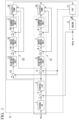
- a fuel supply device A is a device which supplies a predetermined amount of fuel to an engine X, and as shown in FIG. 1 , includes a scheduler 1, a subtractor 2, a controller 3, a subtractor 4, a flow rate control unit 5, a subtractor 6, a speed control unit 7, a subtractor 8, a current control unit 9, an electric pump 10 (first electric pump), an FPV 11 (flow rate measurement unit), a subtractor 12, a flow rate control unit 13, a subtractor 14, a speed control unit 15, a subtractor 16, a current control unit 17, and an electric pump 18 (second electric pump).
- the scheduler 1, the subtractor 2, the controller 3, the subtractor 4, the flow rate control unit 5, the subtractor 6, the speed control unit 7, the subtractor 8, and the current control unit 9 constitute a first control device C1 which controls the electric pump 10 (first electric pump).
- the scheduler 1, the subtractor 2, the controller 3, the subtractor 12, the flow rate control unit 13, the subtractor 14, the speed control unit 15, the subtractor 16, and the current control unit 17 constitute a second control device C2 which controls the electric pump 18 (second electric pump).
- the engine X is a gas turbine which is a flight power source of an aircraft, but may be another type of internal combustion engine.
- the fuel supply device A includes the electric pump 10 (first electric pump) which discharges a fuel toward the engine X at a first flow rate, the electric pump 18 (second electric pump) which discharges the fuel at a second flow rate and merges the fuel discharged at the second flow rate with the fuel discharged at the first flow rate, the first control device C1 which controls the electric pump 10 (first electric pump), and the second control device C2 which controls the electric pump 18 (second electric pump), in which the first control device C1 and the second control device C2 control the first electric pump 10 (first electric pump) and the second electric pump 18 (second electric pump) such that a total flow rate of the first flow rate and the second flow rate is a fuel flow rate target value.
- the scheduler 1 generates an engine rotational speed target value based on a power level angle (PLA) of a pilot and outputs the engine rotational speed target value to the subtractor 2.
- the subtractor 2 is an arithmetic element which calculates a first difference (rotational speed error) between an actual engine rotational speed obtained from the engine X and the engine rotational speed target value input from the scheduler 1, and the subtractor 2 outputs the rotational speed error to the controller 3.
- the controller 3 generates the fuel flow rate target value to be supplied to the engine X based on the rotational speed error input from the subtractor 2, and outputs the fuel flow rate target value to the two subtractors 4 and 12.
- the subtractor 4 is an arithmetic element which calculates a second difference (flow rate error) between the fuel flow rate target value input from the controller 3 and a measured value (actual flow rate of fuel) of an FPV 11 described later, and the subtractor 4 outputs the flow rate error to the flow rate control unit 5.
- the flow rate control unit 5 performs a predetermined control operation on the flow rate error input from the subtractor 4 to generate a rotational speed target value of the electric pump 10, and outputs the rotational speed target value to the subtractor 6.
- the subtractor 6 calculates a third difference (rotational speed error) between the rotational speed target value input from the flow rate control unit 5 and an actual rotational speed (pump rotational speed) input from the electric pump 10, and outputs the rotational speed error to the speed control unit 7.
- the electric pump 10 may include a function of a tachometer which measures the pump rotational speed, or a tachometer (not shown) which measures the pump rotational speed may be provided separately from the electric pump 10.
- the predetermined control operation may be any one of a PID calculation, a PI calculation, a P calculation, or the like, or may be control operations based on other control operation rules.
- the speed control unit 7 performs a predetermined control operation on the rotational speed error input from the subtractor 6 to generate a drive current target value of the electric pump 10, and outputs the drive current target value to the subtractor 8.
- the subtractor 8 calculates a fourth difference (drive current error) between the drive current target value input from the speed control unit 7 and an actual drive current value (pump drive current) input from the electric pump 10, and outputs the drive current error to the current control unit 9.
- the current control unit 9 performs a predetermined control operation on the drive current error input from the subtractor 8 to generate a current operation amount indicating a drive current of the electrically connected electric pump 10, and outputs the current operation amount to the electric pump 10.
- the electric pump 10 is a positive displacement pump which is rotationally driven by an electric motor.
- the electric pump 10 discharges the fuel to the engine X in a rotation state corresponding to the current operation amount.
- a drive circuit (current amplification circuit) is provided between the current control unit 9 and the electric pump 10.
- the drive circuit supplies the drive current corresponding to the current operation amount to the electric pump 10.
- the FPV 11 is a flow rate measurement unit which measures the total flow rate of the fuel discharged at the first flow rate which is a discharge flow rate of the electric pump 10 (first electric pump) and the fuel discharged at the second flow rate which is a discharge flow rate of the electric pump 18 (second electric pump).
- the FPV 11 is provided in a fuel supply flow path, that is, a fuel supply pipe through which the fuel is supplied to the engine X, and the FPV 11 measures a flow rate of the fuel flowing through the fuel supply pipe, that is, the total flow rate, and outputs a measured value to the two subtractors 4 and 12.
- the subtractor 12 is an arithmetic element which calculates the second difference (flow rate error) between the fuel flow rate target value input from the controller 3 and the measured value (fuel flow rate) of the FPV 11, and the subtractor 12 outputs the flow rate error to the flow rate control unit 13.
- the flow rate control unit 13 performs a predetermined control operation on the flow rate error input from the subtractor 12 to generate a rotational speed target value of the electric pump 18, and outputs the rotational speed target value to the subtractor 14.
- the subtractor 14 calculates a fifth difference (rotational speed error) between the rotational speed target value input from the flow rate control unit 13 and an actual rotational speed (pump rotational speed) input from the electric pump 18 and outputs the rotational speed error to the speed control unit 15.
- the electric pump 18 may include a function of a tachometer which measures the pump rotational speed, or a tachometer (not shown) which measures the pump rotational speed may be provided separately from the electric pump 18.
- the speed control unit 15 performs a predetermined control operation on the rotational speed error input from the subtractor 14 to generate a drive current target value of the electric pump 18, and outputs the drive current target value to the subtractor 16.
- the subtractor 16 calculates a sixth difference (drive current error) between the current target value input from the speed control unit 15 and an actual current value (pump drive current) input from the electric pump 18, and outputs the drive current error to the current control unit 17.
- the current control unit 17 performs a predetermined control operation on the drive current error input from the subtractor 16 to generate a current operation amount indicating a drive current of the electrically connected electric pump 18, and outputs the current operation amount to the electric pump 18.
- the electric pump 18 is a positive displacement pump which is rotationally driven by an electric motor. When a drive current corresponding to the current operation amount is input to the electric pump 18, the electric pump 18 discharges the fuel to the engine X in a rotation state corresponding to the current operation amount.
- a drive circuit (current amplification circuit) is provided between the current control unit 17 and the electric pump 18. This drive circuit supplies a drive current corresponding to the current operation amount to the electric pump 18.
- the scheduler 1, the subtractor 2, the controller 3, the subtractor 4, the flow rate control unit 5, the subtractor 6, the speed control unit 7, the subtractor 8, the current control unit 9, the subtractor 12, the flow rate control unit 13, the subtractor 14, the speed control unit 15, the subtractor 16, and the current control unit 17 may be a known computer including a CPU, a RAM, a ROM, or the like capable of performing the above-described calculations and controls. Details of the calculations and controls may be defined by software which can be optionally changed or updated by a user. As shown in FIG. 1 , the members are electrically or electronically connected to each other so that signals can be transmitted and received.
- each of the first control device C1 controlling the electric pump 10 (first electric pump) and the second control device C2 controlling the electric pump 18 (second electric pump) has a quadruple feedback loop, that is, feedback loops related to the engine rotational speed, the fuel flow rate, the pump rotational speed, and the pump drive current.
- the scheduler 1, the subtractor 2, the controller 3, the subtractor 4, the flow rate control unit 5, the subtractor 6, the speed control unit 7, the subtractor 8, and the current control unit 9 constitute the first control device C1 which controls the electric pump 10
- the scheduler 1, the subtractor 2, the controller 3, the subtractor 12, the flow rate control unit 13, the subtractor 14, the speed control unit 15, the subtractor 16, and the current control unit 17 constitute a second control device C2 which controls the electric pump 18.
- the first control device C1 and the second control device C2 control the electric pump 10 and the electric pump 18 based on the first difference (rotational speed error) between the engine rotational speed obtained from the engine X and the engine rotational speed target value.
- the first control device C1 controls the electric pump 10 based on the fourth difference (drive current error) between the actual drive current value of the electric pump 10 and the drive current target value
- the second control device C2 controls the electric pump 18 based on the sixth difference (drive current error) between the actual drive current value of the electric pump 18 and the drive current target value.
- the first control device C1 controls the electric pump 10 based on the third difference (rotational speed error) between the actual rotational speed of the electric pump 10 and the rotational speed target value
- the second control device C2 controls the electric pump 18 based on the fifth difference (rotational speed error) between the actual rotational speed of the electric pump 18 and the rotational speed target value.
- the FPV 11 which measures the total flow rate is further provided, and the first control device C1 and the second control device C2 control the electric pump 10 and the electric pump 18 based on the second difference (flow rate error) between the actual fuel flow rate measured by the FPV 11 and the fuel flow rate target value.
- the fuel supply device A controls the electric pump 10 and the electric pump 18 such that the engine rotational speed, the flow rate of the fuel supplied to the engine X, the pump rotational speed, and the pump drive current are the same as the engine rotational speed target value, the fuel flow rate target value, the rotational speed target value, and the drive current target value, respectively.
- This control is a so-called feedback control.
- the total flow rate of the first flow rate and the second flow rate measured by the FPV 11 are input to the subtractor 4 of the first control device C 1 and the subtractor 12 of the second control device C2. Accordingly, for example, if the first flow rate decreases, the second flow rate increases so that the total flow rate is maintained at the fuel flow rate target value.
- the fuel supply device A of the first embodiment even when any one of the electric pump 10 (first electric pump) and the electric pump 18 (second electric pump) fails and any one of the first flow rate and the second flow rate is "zero", the total flow rate is maintained at the fuel flow rate target value. Therefore, according to the first embodiment, it is possible to provide the fuel supply device of the engine X capable of securing more redundancy than that of the related art.
- a fuel supply device B according to a second embodiment of the present disclosure will be described with reference to FIG. 2 .
- the same reference signs are assigned to the same components as those of the fuel supply device A according to the above-described first embodiment, and repeated descriptions are omitted.
- the fuel supply device B includes the scheduler 1, the subtractor 2, the controller 3, the subtractor 4, the flow rate control unit 5, the subtractor 6, the speed control unit 7, the subtractor 8, the current control unit 9, the electric pump 10 (first electric pump), the subtractor 12, the flow rate control unit 13, the subtractor 14, the speed control unit 15, the subtractor 16, the current control unit 17, the electric pump 18 (second electric pump), a flow rate conversion unit (first flow rate estimation unit) 19, an adder 20, a flow rate conversion unit (second flow rate estimation unit) 21, and an adder 22.
- the scheduler 1, the subtractor 2, the controller 3, the subtractor 4, the flow rate control unit 5, the subtractor 6, the speed control unit 7, the subtractor 8, the current control unit 9, the flow rate conversion unit 19, and the adder 20 constitute a first control device C11 which controls the electric pump 10 (first electric pump).
- the scheduler 1, the subtractor 2, the controller 3, the subtractor 12, the flow rate control unit 13, the subtractor 14, the speed control unit 15, the subtractor 16, the current control unit 17, the flow rate conversion unit 21, and the adder 22 constitute a second control device C22 which controls the electric pump 18 (second electric pump).
- the fuel supply device B has a configuration in which the FPV 11 is deleted in the fuel supply device A and the flow rate conversion unit 19 (first flow rate estimation unit), the adder 20, the flow rate conversion unit 21 (second flow rate estimation unit), and the adder 22 are added instead of the FPV 11.
- the flow rate conversion unit 19 is the first flow rate estimation unit which acquires an estimated first flow rate which is an estimated value of the first flow rate supplied to the engine X based on the actual rotational speed (pump rotational speed) input from the electrically connected electric pump 10.
- the flow rate conversion unit 19 includes a flow rate conversion table indicating a relative relationship between the pump rotational speed and the first flow rate, and the flow rate conversion unit 19 searches the flow rate conversion table using the pump rotational speed input from the electric pump 10 to output the estimated first flow rate corresponding to the pump rotational speed to the two adders 20 and 22.
- the adder 20 calculates a total value of the estimated first flow rate input from the flow rate conversion unit 19 and an estimated second flow rate input from the flow rate conversion unit 21 described later, and outputs this total value to the subtractor 4 as an estimated fuel flow rate.
- the subtractor 4 calculates the second difference (flow rate error) between the fuel flow rate target value input from the controller 3 and the estimated fuel flow rate input from the adder 20, and outputs the second difference to the flow rate control unit 5.
- the subsequent steps are the same as those of the first embodiment.
- the flow rate conversion unit 21 is the second flow rate estimation unit which acquires an estimated second flow rate which is an estimated value of the second flow rate supplied to the engine X based on the actual rotational speed (pump rotational speed) input from the electrically connected electric pump 18.
- the flow rate conversion unit 21 includes a flow rate conversion table indicating a relative relationship between the pump rotational speed and the second flow rate, and the flow rate conversion unit 21 searches the flow rate conversion table using the pump rotational speed input from the electric pump 18 to output the estimated second flow rate corresponding to the pump rotational speed to the two adders 20 and 22.
- the adder 22 calculates a total value of the estimated first flow rate input from the flow rate conversion unit 19 and the estimated second flow rate input from the flow rate conversion unit 21, and outputs this total value to the subtractor 12 as an estimated fuel flow rate.
- the subtractor 12 calculates the fifth difference (flow rate error) between the fuel flow rate target value input from the controller 3 and the estimated fuel flow rate input from the adder 22, and outputs the fifth difference to the flow rate control unit 13.
- the subsequent steps are the same as those of the first embodiment.
- the flow rate conversion unit (first flow rate estimation unit) 19 which acquires the estimated first flow rate which is the estimated value of the first flow rate from the rotational speed of the electric pump 10 and the flow rate conversion unit (second flow rate estimation unit) 21 which acquires the estimated second flow rate which is the estimated value of the second flow rate from the rotational speed of the electric pump 18 are further provided, and the first control device C11 and the second control device C22 control the electric pump 10 and the electric pump 18 based on a difference between the total flow rate of the estimated first flow rate and the estimated second flow rate and the fuel flow rate target value.
- the flow rate conversion unit 19, the adder 20, the flow rate conversion unit 21, and the adder 22 may be a known computer including a CPU, a RAM, a ROM, or the like capable of performing the above-described calculations and controls. Details of the calculations and controls may be defined by software which can be optionally changed or updated by a user. As shown in FIG. 2 , the members are electrically or electronically connected to each other so that signals can be transmitted and received.
- the fuel supply device B controls the electric pump 10 and the electric pump 18 such that the engine rotational speed, the estimated fuel flow rate supplied to the engine X, the pump rotational speed, and the pump drive current are the same as the engine rotational speed target value, the fuel flow rate target value, the rotational speed target value, and the drive current target value, respectively.
- This control is a so-called feedback control.
- the estimated fuel flow rate which is the total flow rate of the estimated first flow rate calculated by the flow rate conversion unit 19 and the estimated second flow rate calculated by the flow rate conversion unit 21 is input to the subtractor 4 of the first control device C11 and the subtractor 12 of the second control device C22. Accordingly, for example, if the first flow rate decreases, the second flow rate increases so that the total flow rate is maintained at the fuel flow rate target value.
- the fuel supply device B of the second embodiment even when any one of the electric pump 10 (first electric pump) and the electric pump 18 (second electric pump) fails and any one of the first flow rate and the second flow rate is "zero", the total flow rate is maintained at the fuel flow rate target value. Therefore, according to the second embodiment, it is possible to provide the fuel supply device of the gas turbine X capable of securing more redundancy than that of the related art.
- each of the first control device C11 and the second control device C22 has a quadruple feedback loop, that is, feedback loops related to the engine rotational speed, the fuel flow rate, the pump rotational speed, and the pump drive current.
- the FPV 11 is adopted as the flow rate measurement unit.
- the present disclosure is not limited to this.
- the flow rate measurement unit is a flow meter for a liquid
- the flow rate measurement unit may adopt another type of flow meter.
- the fuel supply device it is possible to provide a fuel supply device of an engine capable of securing more redundancy than that of the related art.
Landscapes
- Engineering & Computer Science (AREA)
- Chemical & Material Sciences (AREA)
- Combustion & Propulsion (AREA)
- Mechanical Engineering (AREA)
- General Engineering & Computer Science (AREA)
- Control Of Positive-Displacement Pumps (AREA)
- Combined Controls Of Internal Combustion Engines (AREA)
Description
- The disclosure relates to a fuel supply device.
- Priority is claimed on
Japanese Patent Application No. 2017-239676, filed on December 14, 2017 - The following
Patent Document 1 discloses a fuel pump which supplies a fuel to a gas turbine. The fuel pump supplies a fuel using a gear pump whose rotating shaft is connected to an output shaft of the gas turbine via a gear box. -
Patent Documents 2 to 8 disclose a fuel pump and a control device of a fuel pump. -
- Patent Document 1: Japanese Unexamined Patent Application, First Publication No.
JP 2005-232980 - Patent Document 2: Japanese Unexamined Patent Application, First Publication No.
JP H05-157013 - Patent Document 3: Japanese Unexamined Patent Application, First Publication No.
JP 2001-107751 - Patent Document 4: Japanese Unexamined Patent Application, First Publication No.
JP H10-89667 - Patent Document 5: European Patent Publication No.
EP 1344 917 B1 - Patent Document 6: United States Patent Application Publication No.
US 2005/241,318 A1 - Patent Document 7: International Patent Application Publication No.
WO 2015/033 786 A1 - Patent Document 8: German Patent Application Publication No.
DE 699 03 623 T2 - In the above-described fuel supply devices of the related art, the fuel is supplied to the gas turbine by one fuel pump which is rotationally driven by the gas turbine. Accordingly, for example, in a case where the fuel pump or the gear box fails, the fuel cannot be supplied. For example, when the fuel cannot be supplied, this may generate a problem in a case where the gas turbine is an engine of an aircraft.
- The present disclosure is made in consideration of the above-described circumstances, and an object thereof is to provide a fuel supply device of an engine capable of securing more redundancy than that of the related art.
-
- (1) According to a first aspect of the present invention, there is provided a fuel supply device according to
claim 1. According to a second aspect of the present invention, there is provided a fuel supply device according toclaim 5. Further aspects of the present invention are set forth in the dependent claims, the drawings and the following description of embodiments. - (2) In the fuel supply device of (1), the first control device and the second control device may be configured to control the first electric pump and the second electric pump according to a difference between an engine rotational speed obtained from the engine and an engine rotational speed target value.
- (3) In the fuel supply device of (1), the first control device may be configured to control the first electric pump according to a difference between a drive current and a drive current target value of the first electric pump, and the second control device may be configured to control the second electric pump according to a difference between a drive current and a drive current target value of the second electric pump.
- (4) In the fuel supply device of (1), the first control device may be configured to control the first electric pump according to a difference between a rotational speed and a rotational speed target value of the first electric pump, and the second control device may be configured to control the second electric pump according to a difference between a rotational speed and a rotational speed target value of the second electric pump.
- According to the present disclosure, it is possible to provide a fuel supply device of an engine capable of securing more redundancy than that of the related art.
-
-
FIG. 1 is a block diagram showing a system configuration of a fuel supply device according to a first embodiment of the present disclosure. -
FIG. 2 is a block diagram showing a system configuration of a fuel supply device according to a second embodiment of the present disclosure. - Hereinafter, embodiments of the present disclosure will be described with reference to the drawings.
- First, a first embodiment of the present disclosure will be described with reference to
FIG. 1 . A fuel supply device A according to the first embodiment is a device which supplies a predetermined amount of fuel to an engine X, and as shown inFIG. 1 , includes ascheduler 1, asubtractor 2, acontroller 3, asubtractor 4, a flowrate control unit 5, asubtractor 6, aspeed control unit 7, asubtractor 8, a current control unit 9, an electric pump 10 (first electric pump), an FPV 11 (flow rate measurement unit), asubtractor 12, a flowrate control unit 13, a subtractor 14, aspeed control unit 15, asubtractor 16, acurrent control unit 17, and an electric pump 18 (second electric pump). - Among the components, the
scheduler 1, thesubtractor 2, thecontroller 3, thesubtractor 4, the flowrate control unit 5, thesubtractor 6, thespeed control unit 7, thesubtractor 8, and the current control unit 9 constitute a first control device C1 which controls the electric pump 10 (first electric pump). In addition, thescheduler 1, thesubtractor 2, thecontroller 3, thesubtractor 12, the flowrate control unit 13, the subtractor 14, thespeed control unit 15, thesubtractor 16, and thecurrent control unit 17 constitute a second control device C2 which controls the electric pump 18 (second electric pump). For example, the engine X is a gas turbine which is a flight power source of an aircraft, but may be another type of internal combustion engine. - Although details will be described later, the fuel supply device A according to the first embodiment includes the electric pump 10 (first electric pump) which discharges a fuel toward the engine X at a first flow rate, the electric pump 18 (second electric pump) which discharges the fuel at a second flow rate and merges the fuel discharged at the second flow rate with the fuel discharged at the first flow rate, the first control device C1 which controls the electric pump 10 (first electric pump), and the second control device C2 which controls the electric pump 18 (second electric pump), in which the first control device C1 and the second control device C2 control the first electric pump 10 (first electric pump) and the second electric pump 18 (second electric pump) such that a total flow rate of the first flow rate and the second flow rate is a fuel flow rate target value.
- The
scheduler 1 generates an engine rotational speed target value based on a power level angle (PLA) of a pilot and outputs the engine rotational speed target value to thesubtractor 2. Thesubtractor 2 is an arithmetic element which calculates a first difference (rotational speed error) between an actual engine rotational speed obtained from the engine X and the engine rotational speed target value input from thescheduler 1, and thesubtractor 2 outputs the rotational speed error to thecontroller 3. Thecontroller 3 generates the fuel flow rate target value to be supplied to the engine X based on the rotational speed error input from thesubtractor 2, and outputs the fuel flow rate target value to the twosubtractors - The
subtractor 4 is an arithmetic element which calculates a second difference (flow rate error) between the fuel flow rate target value input from thecontroller 3 and a measured value (actual flow rate of fuel) of anFPV 11 described later, and thesubtractor 4 outputs the flow rate error to the flowrate control unit 5. - The flow
rate control unit 5 performs a predetermined control operation on the flow rate error input from thesubtractor 4 to generate a rotational speed target value of theelectric pump 10, and outputs the rotational speed target value to thesubtractor 6. - The
subtractor 6 calculates a third difference (rotational speed error) between the rotational speed target value input from the flowrate control unit 5 and an actual rotational speed (pump rotational speed) input from theelectric pump 10, and outputs the rotational speed error to thespeed control unit 7. Here, theelectric pump 10 may include a function of a tachometer which measures the pump rotational speed, or a tachometer (not shown) which measures the pump rotational speed may be provided separately from theelectric pump 10. - Moreover, in the present specification, for example, the predetermined control operation may be any one of a PID calculation, a PI calculation, a P calculation, or the like, or may be control operations based on other control operation rules.
- The
speed control unit 7 performs a predetermined control operation on the rotational speed error input from thesubtractor 6 to generate a drive current target value of theelectric pump 10, and outputs the drive current target value to thesubtractor 8. - The
subtractor 8 calculates a fourth difference (drive current error) between the drive current target value input from thespeed control unit 7 and an actual drive current value (pump drive current) input from theelectric pump 10, and outputs the drive current error to the current control unit 9. - The current control unit 9 performs a predetermined control operation on the drive current error input from the
subtractor 8 to generate a current operation amount indicating a drive current of the electrically connectedelectric pump 10, and outputs the current operation amount to theelectric pump 10. - The
electric pump 10 is a positive displacement pump which is rotationally driven by an electric motor. When a drive current corresponding to the current operation amount is input to theelectric pump 10, theelectric pump 10 discharges the fuel to the engine X in a rotation state corresponding to the current operation amount. - In addition, although not shown, a drive circuit (current amplification circuit) is provided between the current control unit 9 and the
electric pump 10. The drive circuit supplies the drive current corresponding to the current operation amount to theelectric pump 10. - The
FPV 11 is a flow rate measurement unit which measures the total flow rate of the fuel discharged at the first flow rate which is a discharge flow rate of the electric pump 10 (first electric pump) and the fuel discharged at the second flow rate which is a discharge flow rate of the electric pump 18 (second electric pump). TheFPV 11 is provided in a fuel supply flow path, that is, a fuel supply pipe through which the fuel is supplied to the engine X, and theFPV 11 measures a flow rate of the fuel flowing through the fuel supply pipe, that is, the total flow rate, and outputs a measured value to the twosubtractors - The
subtractor 12 is an arithmetic element which calculates the second difference (flow rate error) between the fuel flow rate target value input from thecontroller 3 and the measured value (fuel flow rate) of theFPV 11, and thesubtractor 12 outputs the flow rate error to the flowrate control unit 13. - The flow
rate control unit 13 performs a predetermined control operation on the flow rate error input from thesubtractor 12 to generate a rotational speed target value of theelectric pump 18, and outputs the rotational speed target value to the subtractor 14. - The subtractor 14 calculates a fifth difference (rotational speed error) between the rotational speed target value input from the flow
rate control unit 13 and an actual rotational speed (pump rotational speed) input from theelectric pump 18 and outputs the rotational speed error to thespeed control unit 15. Here, theelectric pump 18 may include a function of a tachometer which measures the pump rotational speed, or a tachometer (not shown) which measures the pump rotational speed may be provided separately from theelectric pump 18. - The
speed control unit 15 performs a predetermined control operation on the rotational speed error input from the subtractor 14 to generate a drive current target value of theelectric pump 18, and outputs the drive current target value to thesubtractor 16. - The
subtractor 16 calculates a sixth difference (drive current error) between the current target value input from thespeed control unit 15 and an actual current value (pump drive current) input from theelectric pump 18, and outputs the drive current error to thecurrent control unit 17. - The
current control unit 17 performs a predetermined control operation on the drive current error input from thesubtractor 16 to generate a current operation amount indicating a drive current of the electrically connectedelectric pump 18, and outputs the current operation amount to theelectric pump 18. - The
electric pump 18 is a positive displacement pump which is rotationally driven by an electric motor. When a drive current corresponding to the current operation amount is input to theelectric pump 18, theelectric pump 18 discharges the fuel to the engine X in a rotation state corresponding to the current operation amount. - In addition, although not shown, a drive circuit (current amplification circuit) is provided between the
current control unit 17 and theelectric pump 18. This drive circuit supplies a drive current corresponding to the current operation amount to theelectric pump 18. - Here, the
scheduler 1, thesubtractor 2, thecontroller 3, thesubtractor 4, the flowrate control unit 5, thesubtractor 6, thespeed control unit 7, thesubtractor 8, the current control unit 9, thesubtractor 12, the flowrate control unit 13, the subtractor 14, thespeed control unit 15, thesubtractor 16, and thecurrent control unit 17 may be a known computer including a CPU, a RAM, a ROM, or the like capable of performing the above-described calculations and controls. Details of the calculations and controls may be defined by software which can be optionally changed or updated by a user. As shown inFIG. 1 , the members are electrically or electronically connected to each other so that signals can be transmitted and received. - That is, in the fuel supply device A according to the first embodiment, each of the first control device C1 controlling the electric pump 10 (first electric pump) and the second control device C2 controlling the electric pump 18 (second electric pump) has a quadruple feedback loop, that is, feedback loops related to the engine rotational speed, the fuel flow rate, the pump rotational speed, and the pump drive current.
- Moreover, as described above, in the present disclosure, the
scheduler 1, thesubtractor 2, thecontroller 3, thesubtractor 4, the flowrate control unit 5, thesubtractor 6, thespeed control unit 7, thesubtractor 8, and the current control unit 9 constitute the first control device C1 which controls theelectric pump 10, and thescheduler 1, thesubtractor 2, thecontroller 3, thesubtractor 12, the flowrate control unit 13, the subtractor 14, thespeed control unit 15, thesubtractor 16, and thecurrent control unit 17 constitute a second control device C2 which controls theelectric pump 18. - Therefore, in the present disclosure having the above-described configuration, the first control device C1 and the second control device C2 control the
electric pump 10 and theelectric pump 18 based on the first difference (rotational speed error) between the engine rotational speed obtained from the engine X and the engine rotational speed target value. - Further, in the present disclosure, the first control device C1 controls the
electric pump 10 based on the fourth difference (drive current error) between the actual drive current value of theelectric pump 10 and the drive current target value, and the second control device C2 controls theelectric pump 18 based on the sixth difference (drive current error) between the actual drive current value of theelectric pump 18 and the drive current target value. - Further, in the present disclosure, the first control device C1 controls the
electric pump 10 based on the third difference (rotational speed error) between the actual rotational speed of theelectric pump 10 and the rotational speed target value, and the second control device C2 controls theelectric pump 18 based on the fifth difference (rotational speed error) between the actual rotational speed of theelectric pump 18 and the rotational speed target value. - Further, in the present disclosure, the
FPV 11 which measures the total flow rate is further provided, and the first control device C1 and the second control device C2 control theelectric pump 10 and theelectric pump 18 based on the second difference (flow rate error) between the actual fuel flow rate measured by theFPV 11 and the fuel flow rate target value. - Subsequently, an operation of the fuel supply device A according to the first embodiment will be described in detail.
- As a basic operation, the fuel supply device A controls the
electric pump 10 and theelectric pump 18 such that the engine rotational speed, the flow rate of the fuel supplied to the engine X, the pump rotational speed, and the pump drive current are the same as the engine rotational speed target value, the fuel flow rate target value, the rotational speed target value, and the drive current target value, respectively. This control is a so-called feedback control. - Here, the total flow rate of the first flow rate and the second flow rate measured by the
FPV 11 are input to thesubtractor 4 of the firstcontrol device C 1 and thesubtractor 12 of the second control device C2. Accordingly, for example, if the first flow rate decreases, the second flow rate increases so that the total flow rate is maintained at the fuel flow rate target value. - That is, according to the fuel supply device A of the first embodiment, even when any one of the electric pump 10 (first electric pump) and the electric pump 18 (second electric pump) fails and any one of the first flow rate and the second flow rate is "zero", the total flow rate is maintained at the fuel flow rate target value. Therefore, according to the first embodiment, it is possible to provide the fuel supply device of the engine X capable of securing more redundancy than that of the related art.
- Next, a fuel supply device B according to a second embodiment of the present disclosure will be described with reference to
FIG. 2 . In addition, in the following descriptions, in the fuel supply device B according to the second embodiment, the same reference signs are assigned to the same components as those of the fuel supply device A according to the above-described first embodiment, and repeated descriptions are omitted. - As shown in
FIG. 2 , the fuel supply device B according to the second embodiment includes thescheduler 1, thesubtractor 2, thecontroller 3, thesubtractor 4, the flowrate control unit 5, thesubtractor 6, thespeed control unit 7, thesubtractor 8, the current control unit 9, the electric pump 10 (first electric pump), thesubtractor 12, the flowrate control unit 13, the subtractor 14, thespeed control unit 15, thesubtractor 16, thecurrent control unit 17, the electric pump 18 (second electric pump), a flow rate conversion unit (first flow rate estimation unit) 19, anadder 20, a flow rate conversion unit (second flow rate estimation unit) 21, and anadder 22. - In the second embodiment, the
scheduler 1, thesubtractor 2, thecontroller 3, thesubtractor 4, the flowrate control unit 5, thesubtractor 6, thespeed control unit 7, thesubtractor 8, the current control unit 9, the flowrate conversion unit 19, and theadder 20 constitute a first control device C11 which controls the electric pump 10 (first electric pump). Moreover, thescheduler 1, thesubtractor 2, thecontroller 3, thesubtractor 12, the flowrate control unit 13, the subtractor 14, thespeed control unit 15, thesubtractor 16, thecurrent control unit 17, the flowrate conversion unit 21, and theadder 22 constitute a second control device C22 which controls the electric pump 18 (second electric pump). - That is, the fuel supply device B has a configuration in which the
FPV 11 is deleted in the fuel supply device A and the flow rate conversion unit 19 (first flow rate estimation unit), theadder 20, the flow rate conversion unit 21 (second flow rate estimation unit), and theadder 22 are added instead of theFPV 11. - The flow
rate conversion unit 19 is the first flow rate estimation unit which acquires an estimated first flow rate which is an estimated value of the first flow rate supplied to the engine X based on the actual rotational speed (pump rotational speed) input from the electrically connectedelectric pump 10. - For example, the flow
rate conversion unit 19 includes a flow rate conversion table indicating a relative relationship between the pump rotational speed and the first flow rate, and the flowrate conversion unit 19 searches the flow rate conversion table using the pump rotational speed input from theelectric pump 10 to output the estimated first flow rate corresponding to the pump rotational speed to the twoadders adder 20 calculates a total value of the estimated first flow rate input from the flowrate conversion unit 19 and an estimated second flow rate input from the flowrate conversion unit 21 described later, and outputs this total value to thesubtractor 4 as an estimated fuel flow rate. - The
subtractor 4 calculates the second difference (flow rate error) between the fuel flow rate target value input from thecontroller 3 and the estimated fuel flow rate input from theadder 20, and outputs the second difference to the flowrate control unit 5. The subsequent steps are the same as those of the first embodiment. - The flow
rate conversion unit 21 is the second flow rate estimation unit which acquires an estimated second flow rate which is an estimated value of the second flow rate supplied to the engine X based on the actual rotational speed (pump rotational speed) input from the electrically connectedelectric pump 18. - For example, the flow
rate conversion unit 21 includes a flow rate conversion table indicating a relative relationship between the pump rotational speed and the second flow rate, and the flowrate conversion unit 21 searches the flow rate conversion table using the pump rotational speed input from theelectric pump 18 to output the estimated second flow rate corresponding to the pump rotational speed to the twoadders adder 22 calculates a total value of the estimated first flow rate input from the flowrate conversion unit 19 and the estimated second flow rate input from the flowrate conversion unit 21, and outputs this total value to thesubtractor 12 as an estimated fuel flow rate. - The
subtractor 12 calculates the fifth difference (flow rate error) between the fuel flow rate target value input from thecontroller 3 and the estimated fuel flow rate input from theadder 22, and outputs the fifth difference to the flowrate control unit 13. The subsequent steps are the same as those of the first embodiment. - That is, in the second embodiment, the flow rate conversion unit (first flow rate estimation unit) 19 which acquires the estimated first flow rate which is the estimated value of the first flow rate from the rotational speed of the
electric pump 10 and the flow rate conversion unit (second flow rate estimation unit) 21 which acquires the estimated second flow rate which is the estimated value of the second flow rate from the rotational speed of theelectric pump 18 are further provided, and the first control device C11 and the second control device C22 control theelectric pump 10 and theelectric pump 18 based on a difference between the total flow rate of the estimated first flow rate and the estimated second flow rate and the fuel flow rate target value. - Here, the flow
rate conversion unit 19, theadder 20, the flowrate conversion unit 21, and theadder 22 may be a known computer including a CPU, a RAM, a ROM, or the like capable of performing the above-described calculations and controls. Details of the calculations and controls may be defined by software which can be optionally changed or updated by a user. As shown inFIG. 2 , the members are electrically or electronically connected to each other so that signals can be transmitted and received. - Subsequently, an operation of the fuel supply device B according to the second embodiment will be described in detail.
- As a basic operation, the fuel supply device B controls the
electric pump 10 and theelectric pump 18 such that the engine rotational speed, the estimated fuel flow rate supplied to the engine X, the pump rotational speed, and the pump drive current are the same as the engine rotational speed target value, the fuel flow rate target value, the rotational speed target value, and the drive current target value, respectively. This control is a so-called feedback control. - Here, the estimated fuel flow rate which is the total flow rate of the estimated first flow rate calculated by the flow
rate conversion unit 19 and the estimated second flow rate calculated by the flowrate conversion unit 21 is input to thesubtractor 4 of the first control device C11 and thesubtractor 12 of the second control device C22. Accordingly, for example, if the first flow rate decreases, the second flow rate increases so that the total flow rate is maintained at the fuel flow rate target value. - That is, according to the fuel supply device B of the second embodiment, even when any one of the electric pump 10 (first electric pump) and the electric pump 18 (second electric pump) fails and any one of the first flow rate and the second flow rate is "zero", the total flow rate is maintained at the fuel flow rate target value. Therefore, according to the second embodiment, it is possible to provide the fuel supply device of the gas turbine X capable of securing more redundancy than that of the related art.
- In addition, the present disclosure is not limited to the embodiments, and for example, the following modification examples are considered. (1) In the embodiments, each of the first control device C11 and the second control device C22 has a quadruple feedback loop, that is, feedback loops related to the engine rotational speed, the fuel flow rate, the pump rotational speed, and the pump drive current.
- (2) In the first embodiment, the
FPV 11 is adopted as the flow rate measurement unit. However, the present disclosure is not limited to this. For example, as long as the flow rate measurement unit is a flow meter for a liquid, the flow rate measurement unit may adopt another type of flow meter. - According to the fuel supply device according to the present disclosure, it is possible to provide a fuel supply device of an engine capable of securing more redundancy than that of the related art.
-
- A, B: fuel supply device
- 1: scheduler
- 2, 4, 6, 8, 12, 14, 16: subtractor
- 3: controller
- 5, 13: flow rate control unit
- 7, 15: speed control unit
- 9: current control unit
- 10: electric pump (first electric pump)
- 11: FPV (flow rate measurement unit)
- 18: electric pump (second electric pump)
- 19: flow rate conversion unit (first flow rate estimation unit)
- 20, 22: adder
- 21: flow rate conversion unit (second flow rate estimation unit)
Claims (8)
- A fuel supply device (A) comprising:a first electric pump (10) which discharges a fuel toward an engine (X) at a first flow rate;a second electric pump (18) which discharges the fuel toward the engine (X) at a second flow rate;a first control device (C1) which is configured to control the first electric pump (10);a second control device (C2) which is configured to control the second electric pump (18); anda flow rate measurement unit (FPV) which measures a total flow rate of the first flow rate and the second flow rate,wherein the fuel discharged at the first flow rate and the fuel discharged at the second flow rate are configured to be merged, the first control device (C1) and the second control device (C2) are configured to control the first electric pump (10) and the second electric pump (18) such that the total flow rate of the first flow rate and the second flow rate is a fuel flow rate target value,the first control device (C1) and the second control device (C2) are configured to control the first electric pump (10) and the second electric pump (18) according to a difference between a measured value of the flow rate measurement unit (FPV) and the fuel flow rate target value, characterized in that:the first control device (C1) includes a scheduler (1), a first subtractor (2) which is electrically connected to the scheduler (1) and the engine (X), a controller (3) which is electrically connected to the first subtractor (2), a second subtractor (4) which is electrically connected to the controller (3) and the flow rate measurement unit (FPV), a first flow rate control unit (5) which is electrically connected to the second subtractor (4), a third subtractor (6) which is electrically connected to the first flow rate control unit (5) and the first electric pump (10), a first speed control unit (7) which is electrically connected to the third subtractor (6), a fourth subtractor (8) which is electrically connected to the first speed control unit (7) and the first electric pump (10), and a first current control unit (9) which is electrically connected to the fourth subtractor (8), andthe second control device (2) includes the scheduler (1), the first subtractor (2), the controller (3), a fifth subtractor (12) which is electrically connected to the controller (3) and the flow rate measurement unit (FPV), a second flow rate control unit (13) which is electrically connected to the fifth subtractor (12), a sixth subtractor (14) which is electrically connected to the second flow rate control unit (13) and the second electric pump (18), a second speed control unit (15) which is electrically connected to the sixth subtractor (14), a seventh subtractor (16) which is electrically connected to the second speed control unit (15) and the second electric pump (18), and a second current control unit (17) which is electrically connected to the seventh subtractor (16),the first subtractor (2) is configured to calculate a first difference between an engine rotational speed target value input from the scheduler (1) and an engine rotational speed input from the engine (X) and output the first difference to the controller (3), the second subtractor (4) is configured to calculate a second difference between the fuel flow rate target value input from the controller (3) and a fuel flow rate input from the flow rate measurement unit (FPV), and output the second difference to the first flow rate control unit (5),the third subtractor (6) is configured to calculate a third difference between a rotational speed target value input from the first flow rate control unit (5) and a pump rotational speed input from the first electric pump (10), and output the third difference to the first speed control unit (7),the fourth subtractor (8) is configured to calculate a fourth difference between a drive current target value of the first electric pump (10) input from the first speed control unit (7) and a pump drive current input from the first electric pump (10), and output the fourth difference to the first current control unit (9),the fifth subtractor (12) is configured to calculate the second difference between the fuel flow rate target value input from the controller (3) and the fuel flow rate input from the flow rate measurement unit (FPV), and output the second difference to the second flow rate control unit (13),the sixth subtractor (14) is configured to calculate a fifth difference between a rotational speed target value input from the second flow rate control unit (13) and a pump rotational speed input from the second electric pump (18), and output the fifth difference to the second speed control unit (15), andthe seventh subtractor (16) is configured to calculate a sixth difference between a drive current target value of the second electric pump (18) input from the second speed control unit (15) and a pump drive current input from the second electric pump (18), and output the sixth difference to the second current control unit (17).
- The fuel supply device (A) according to claim 1,
wherein the first control device (C1) and the second control device (C2) are configured to control the first electric pump (10) and the second electric pump (18) according to the first difference between the engine rotational speed obtained from the engine (X) and the engine rotational speed target value. - The fuel supply device (A) according to claim 1 or 2,wherein the first control device (C1) is configured to control the first electric pump (10) according to the fourth difference between the drive current and the drive current target value of the first electric pump (10), andwherein the second control device (C2) is configured to control the second electric pump (18) according to the sixth difference between the drive current and the drive current target value of the second electric pump (18).
- The fuel supply device (A) according to any one of claims 1 to 3,wherein the first control device (C1) is configured to control the first electric pump (10) according to the third difference between the rotational speed and the rotational speed target value of the first electric pump (10), andwherein the second control device (C2) is configured to control the second electric pump (18) according to the fifth difference between the rotational speed and the rotational speed target value of the second electric pump (18).
- A fuel supply device (B) comprising:a first electric pump (10) which discharges a fuel toward an engine (X) at a first flow rate;a second electric pump (18) which discharges the fuel toward the engine (X) at a second flow rate;a first control device (C11) which is configured to control the first electric pump (10);a second control device (C22) which is configured to control the second electric pump (18);a first flow rate estimation unit (19) which acquires an estimated first flow rate which is an estimated value of the first flow rate, from a rotational speed of the first electric pump (10); anda second flow rate estimation unit (21) which acquires an estimated second flow rate which is an estimated value of the second flow rate, from a rotational speed of the second electric pump (18), wherein:the fuel discharged at the first flow rate and the fuel discharged at the second flow rate are configured tobe merged, the first control device (C11) and the second control device (C22) are configured to control the first electric pump (10) and the second electric pump (18) such that the total flow rate of the first flow rate and the second flow rate is a fuel flow rate target value,the first control device (C11) and the second control device (C22) are configured to control the first electric pump (10) and the second electric pump (18) according to a difference between a total flow rate of the estimated first flow rate and the estimated second flow rate, and the fuel flow rate target value, characterized in that:the first control device (C11) includes a scheduler (1), a first subtractor (2) which is electrically connected to the scheduler (1) and the engine (X), a controller (3) which is electrically connected to the first subtractor (2), a second subtractor (4) which is electrically connected to the controller (3) and a first adder (20), a first flow rate control unit (5) which is electrically connected to the second subtractor (4), a third subtractor (6) which is electrically connected to the first flow rate control unit (5) and the first electric pump (10), a first speed control unit (7) which is electrically connected to the third subtractor (6), a fourth subtractor (6) which is electrically connected to the first speed control unit (7) and the first electric pump (10), a first current control unit (9) which is electrically connected to the fourth subtractor (6), the first flow rate estimation unit (19) which is electrically connected to the first electric pump (10), and the first adder (20) which is electrically connected to the first flow rate estimation unit (19) and the second flow rate estimation unit (21), andthe second control device (C22) includes the scheduler (1), the first subtractor (2), the controller (3), a fifth subtractor (12) which is electrically connected to the controller (3) and a second adder (22), a second flow rate control unit (13) which is electrically connected to the fifth subtractor (12), a sixth subtractor (14) which is electrically connected to the second flow rate control unit (13) and the second electric pump (18), a second speed control unit (15) which is electrically connected to the sixth subtractor (14), a seventh subtractor (16) which is electrically connected to the second speed control unit (15) and the second electric pump (18), a second current control unit (17) which is electrically connected to the seventh subtractor (16), the second flow rate estimation unit (21) which is electrically connected to the second electric pump (18), and the second adder (22) which is electrically connected the second flow rate estimation unit (21) and the first flow rate estimation unit (19),the first subtractor (2) is configured to calculate a first difference between an engine rotational speed target value input from the scheduler (1) and an engine rotational speed input from the engine (X), and output the first difference to the controller (3), the second subtractor (4) is configured to calculate a second difference between the fuel flow rate target value input from the controller (3) and an estimated fuel flow rate input from the first adder (20), and output the second difference to the first flow rate control unit (5),the third subtractor (6) is configured to calculate a third difference between a rotational speed target value input from the first flow rate control unit (5) and a pump rotational speed input from the first electric pump (10), and output the third difference to the first speed control unit (7),the fourth subtractor (8) is configured to calculate a fourth difference between a drive current target value of the first electric pump (10) input from the first speed control unit (7) and a pump drive current input from the first electric pump (10), and output the fourth difference to the first current control unit (9),the first adder (20) is configured to calculate a total value of the estimated first flow rate input from the first flow rate estimation unit (19) and the estimated second flow rate input from the second flow rate estimation unit (21), and input the total value to the second subtractor (4),the fifth subtractor (12) is configured to calculate a fifth difference between the fuel flow rate target value input from the controller (3) and an estimated fuel flow rate input from the second adder (22), and output the fifth difference to the second flow rate control unit (13),the sixth subtractor (14) is configured to calculate a sixth difference between a rotational speed target value input from the second flow rate control unit (13) and a pump rotational speed input from the second electric pump (18), and output the sixth difference to the second speed control unit (15),the seventh subtractor (16) is configured to calculate a seventh difference between a drive current target value of the second electric pump (18) input from the second speed control unit (15) and a pump drive current input from the second electric pump (18), and output the seventh difference to the second current control unit (17), andthe second adder (22) is configured to calculate the total value of the estimated second flow rate input from the second flow rate estimation unit (21) and the estimated first flow rate input from the first flow rate estimation unit (19), and input the total value to the fifth subtractor (12).
- The fuel supply device (B) according to claim 5, wherein the first control device (C11) and the second control device (C22) are configured to control the first electric pump (10) and the second electric pump (18) according to the first difference between the engine rotational speed obtained from the engine (X) and the engine rotational speed target value.
- The fuel supply device (B) according to claim 5 or 6, wherein:the first control device (C11) is configured to control the first electric pump (10) according to the fourth difference between the drive current and the drive current target value of the first electric pump (10), andthe second control device (C22) is configured to control the second electric pump (18) according to the seventh difference between the drive current and the drive current target value of the second electric pump (18).
- The fuel supply device (B) according to any one of claims 5 to 7, wherein:the first control device (C11) is configured to control the first electric pump (10) according to the third difference between the rotational speed and the rotational speed target value of the first electric pump (10), andthe second control device (C22) is configured to control the second electric pump (18) according to the sixth difference between the rotational speed and the rotational speed target value of the second electric pump (18).
Applications Claiming Priority (2)
| Application Number | Priority Date | Filing Date | Title |
|---|---|---|---|
| JP2017239676 | 2017-12-14 | ||
| PCT/JP2018/045478 WO2019117135A1 (en) | 2017-12-14 | 2018-12-11 | Fuel supply device |
Publications (3)
| Publication Number | Publication Date |
|---|---|
| EP3726034A1 EP3726034A1 (en) | 2020-10-21 |
| EP3726034A4 EP3726034A4 (en) | 2021-09-01 |
| EP3726034B1 true EP3726034B1 (en) | 2024-05-01 |
Family
ID=66820914
Family Applications (1)
| Application Number | Title | Priority Date | Filing Date |
|---|---|---|---|
| EP18888452.2A Active EP3726034B1 (en) | 2017-12-14 | 2018-12-11 | Fuel supply device |
Country Status (5)
| Country | Link |
|---|---|
| US (1) | US11761382B2 (en) |
| EP (1) | EP3726034B1 (en) |
| JP (1) | JP6891977B2 (en) |
| CA (1) | CA3085284C (en) |
| WO (1) | WO2019117135A1 (en) |
Families Citing this family (1)
| Publication number | Priority date | Publication date | Assignee | Title |
|---|---|---|---|---|
| FR3128198A1 (en) * | 2021-10-20 | 2023-04-21 | Zipair | Method for controlling a thrust unit for a propulsion device |
Family Cites Families (16)
| Publication number | Priority date | Publication date | Assignee | Title |
|---|---|---|---|---|
| FR2571780B1 (en) * | 1984-10-17 | 1987-01-02 | Snecma | FUEL DOSING DEVICE, FOR EXAMPLE FOR A GAS TURBINE |
| JPH05157013A (en) | 1991-06-25 | 1993-06-22 | Nissan Motor Co Ltd | Fuel supply device for multi-fuel engine |
| EP1067282A2 (en) | 1993-03-03 | 2001-01-10 | KETEMA AEROSPACE & ELECTRONICS DIVISION | Integrated engine control system for a gas turbine engine |
| JPH1089667A (en) | 1996-09-13 | 1998-04-10 | Ishikawajima Harima Heavy Ind Co Ltd | Fuel pump service-in / service-out circuit |
| SE521324C2 (en) * | 1998-05-15 | 2003-10-21 | Abb Ab | Apparatus for supplying a liquid fuel to a burner means |
| JP2001107751A (en) | 1999-10-05 | 2001-04-17 | Honda Motor Co Ltd | Aircraft gas turbine engine controller |
| GB0023727D0 (en) * | 2000-09-27 | 2000-11-08 | Lucas Industries Ltd | Control system |
| GB0206222D0 (en) * | 2002-03-15 | 2002-05-01 | Lucas Industries Ltd | Control system |
| JP3975232B2 (en) | 2002-10-22 | 2007-09-12 | 川崎重工業株式会社 | Control method and control system for gas turbine engine |
| US6996970B2 (en) | 2003-09-30 | 2006-02-14 | Honeywell International Inc. | High accuracy fuel metering system for turbine engines |
| JP4200919B2 (en) | 2004-02-17 | 2008-12-24 | 株式会社Ihi | Gear pump |
| US7197879B2 (en) * | 2004-04-29 | 2007-04-03 | Honeywell International, Inc. | Multiple electric fuel metering systems for gas turbine applications |
| US8646313B2 (en) * | 2009-06-22 | 2014-02-11 | Ford Global Technologies, Llc | System and method to provide lubrication for a plug-in hybrid |
| JP6131785B2 (en) * | 2013-08-30 | 2017-05-24 | 株式会社Ihi | Aircraft engine fuel supply system |
| JP2015052315A (en) * | 2013-09-09 | 2015-03-19 | 株式会社Ihi | Fuel supply system for gas turbine engine |
| US9512783B2 (en) * | 2014-11-14 | 2016-12-06 | Hamilton Sundstrand Corporation | Aircraft fuel system |
-
2018
- 2018-12-11 EP EP18888452.2A patent/EP3726034B1/en active Active
- 2018-12-11 JP JP2019559654A patent/JP6891977B2/en active Active
- 2018-12-11 CA CA3085284A patent/CA3085284C/en active Active
- 2018-12-11 WO PCT/JP2018/045478 patent/WO2019117135A1/en not_active Ceased
-
2020
- 2020-06-05 US US16/893,534 patent/US11761382B2/en active Active
Also Published As
| Publication number | Publication date |
|---|---|
| CA3085284C (en) | 2022-07-19 |
| US11761382B2 (en) | 2023-09-19 |
| JPWO2019117135A1 (en) | 2020-04-02 |
| EP3726034A1 (en) | 2020-10-21 |
| US20200300170A1 (en) | 2020-09-24 |
| CA3085284A1 (en) | 2019-06-20 |
| EP3726034A4 (en) | 2021-09-01 |
| JP6891977B2 (en) | 2021-06-18 |
| WO2019117135A1 (en) | 2019-06-20 |
Similar Documents
| Publication | Publication Date | Title |
|---|---|---|
| JP4741606B2 (en) | Pump control device for hydraulic working machine, pump control method, and construction machine | |
| US11352959B2 (en) | Fuel supply control device | |
| RU2599414C2 (en) | Method and device for monitoring servo-valve actuation system | |
| WO2008026544A1 (en) | Hydraulic unit and method of controlling speed of motor in hydraulic unit | |
| EP2479107B1 (en) | Aircraft flight control system | |
| WO2016017674A1 (en) | Shovel | |
| EP3244040B1 (en) | Multivariable fuel control and estimator (mfce) for preventing combustor blowout | |
| EP3399155B1 (en) | Method and system for accommodating loss of a torque signal | |
| EP3726034B1 (en) | Fuel supply device | |
| CN113167179B (en) | System and method for controlling aircraft turbine engine speed with fault management | |
| US20180163862A1 (en) | Control system for hydraulically powered ac generator | |
| CN103502093B (en) | Marine propulsion system and possess the boats and ships of this marine propulsion system | |
| WO2014002435A1 (en) | Horsepower limiting device and horsepower limiting method | |
| KR20160007430A (en) | Method for the control and protection of a gas turbine and gas turbine using such method | |
| CN113646521B (en) | Method and system for controlling turbine engine with control saturation management | |
| RU2542631C1 (en) | System to control dual-shaft gas turbine compressor stator position | |
| EP4553310A1 (en) | Blended n-dot and ratio unit reference acceleration control architecture for gas turbine engine | |
| RU2564747C2 (en) | Method and device for automatic control over expansion engine speed | |
| KR101891276B1 (en) | Apparatus for controling velocity | |
| CN120265872A (en) | Idle speed maintenance control method and device | |
| JP2011135652A (en) | Motor control device and motor control method | |
| US20130315753A1 (en) | Speed control of engine pump via summing differential |
Legal Events
| Date | Code | Title | Description |
|---|---|---|---|
| STAA | Information on the status of an ep patent application or granted ep patent |
Free format text: STATUS: THE INTERNATIONAL PUBLICATION HAS BEEN MADE |
|
| PUAI | Public reference made under article 153(3) epc to a published international application that has entered the european phase |
Free format text: ORIGINAL CODE: 0009012 |
|
| STAA | Information on the status of an ep patent application or granted ep patent |
Free format text: STATUS: REQUEST FOR EXAMINATION WAS MADE |
|
| 17P | Request for examination filed |
Effective date: 20200714 |
|
| AK | Designated contracting states |
Kind code of ref document: A1 Designated state(s): AL AT BE BG CH CY CZ DE DK EE ES FI FR GB GR HR HU IE IS IT LI LT LU LV MC MK MT NL NO PL PT RO RS SE SI SK SM TR |
|
| AX | Request for extension of the european patent |
Extension state: BA ME |
|
| DAV | Request for validation of the european patent (deleted) | ||
| DAX | Request for extension of the european patent (deleted) | ||
| A4 | Supplementary search report drawn up and despatched |
Effective date: 20210730 |
|
| RIC1 | Information provided on ipc code assigned before grant |
Ipc: F02D 23/02 20060101AFI20210726BHEP Ipc: F02C 7/236 20060101ALI20210726BHEP Ipc: F02C 9/30 20060101ALI20210726BHEP Ipc: F23R 3/28 20060101ALI20210726BHEP Ipc: F02D 41/30 20060101ALI20210726BHEP Ipc: F02C 9/26 20060101ALI20210726BHEP Ipc: F02C 9/34 20060101ALI20210726BHEP |
|
| GRAP | Despatch of communication of intention to grant a patent |
Free format text: ORIGINAL CODE: EPIDOSNIGR1 |
|
| STAA | Information on the status of an ep patent application or granted ep patent |
Free format text: STATUS: GRANT OF PATENT IS INTENDED |
|
| INTG | Intention to grant announced |
Effective date: 20231215 |
|
| GRAS | Grant fee paid |
Free format text: ORIGINAL CODE: EPIDOSNIGR3 |
|
| GRAA | (expected) grant |
Free format text: ORIGINAL CODE: 0009210 |
|
| STAA | Information on the status of an ep patent application or granted ep patent |
Free format text: STATUS: THE PATENT HAS BEEN GRANTED |
|
| AK | Designated contracting states |
Kind code of ref document: B1 Designated state(s): AL AT BE BG CH CY CZ DE DK EE ES FI FR GB GR HR HU IE IS IT LI LT LU LV MC MK MT NL NO PL PT RO RS SE SI SK SM TR |
|
| REG | Reference to a national code |
Ref country code: GB Ref legal event code: FG4D |
|
| REG | Reference to a national code |
Ref country code: CH Ref legal event code: EP |
|
| REG | Reference to a national code |
Ref country code: DE Ref legal event code: R096 Ref document number: 602018069101 Country of ref document: DE |
|
| REG | Reference to a national code |
Ref country code: IE Ref legal event code: FG4D |
|
| REG | Reference to a national code |
Ref country code: LT Ref legal event code: MG9D |
|
| REG | Reference to a national code |
Ref country code: NL Ref legal event code: MP Effective date: 20240501 |
|
| PG25 | Lapsed in a contracting state [announced via postgrant information from national office to epo] |
Ref country code: IS Free format text: LAPSE BECAUSE OF FAILURE TO SUBMIT A TRANSLATION OF THE DESCRIPTION OR TO PAY THE FEE WITHIN THE PRESCRIBED TIME-LIMIT Effective date: 20240901 |
|
| PG25 | Lapsed in a contracting state [announced via postgrant information from national office to epo] |
Ref country code: BG Free format text: LAPSE BECAUSE OF FAILURE TO SUBMIT A TRANSLATION OF THE DESCRIPTION OR TO PAY THE FEE WITHIN THE PRESCRIBED TIME-LIMIT Effective date: 20240501 |
|
| PG25 | Lapsed in a contracting state [announced via postgrant information from national office to epo] |
Ref country code: HR Free format text: LAPSE BECAUSE OF FAILURE TO SUBMIT A TRANSLATION OF THE DESCRIPTION OR TO PAY THE FEE WITHIN THE PRESCRIBED TIME-LIMIT Effective date: 20240501 Ref country code: FI Free format text: LAPSE BECAUSE OF FAILURE TO SUBMIT A TRANSLATION OF THE DESCRIPTION OR TO PAY THE FEE WITHIN THE PRESCRIBED TIME-LIMIT Effective date: 20240501 |
|
| PG25 | Lapsed in a contracting state [announced via postgrant information from national office to epo] |
Ref country code: GR Free format text: LAPSE BECAUSE OF FAILURE TO SUBMIT A TRANSLATION OF THE DESCRIPTION OR TO PAY THE FEE WITHIN THE PRESCRIBED TIME-LIMIT Effective date: 20240802 |
|
| PG25 | Lapsed in a contracting state [announced via postgrant information from national office to epo] |
Ref country code: PT Free format text: LAPSE BECAUSE OF FAILURE TO SUBMIT A TRANSLATION OF THE DESCRIPTION OR TO PAY THE FEE WITHIN THE PRESCRIBED TIME-LIMIT Effective date: 20240902 |
|
| REG | Reference to a national code |
Ref country code: AT Ref legal event code: MK05 Ref document number: 1682621 Country of ref document: AT Kind code of ref document: T Effective date: 20240501 |
|
| PG25 | Lapsed in a contracting state [announced via postgrant information from national office to epo] |
Ref country code: NL Free format text: LAPSE BECAUSE OF FAILURE TO SUBMIT A TRANSLATION OF THE DESCRIPTION OR TO PAY THE FEE WITHIN THE PRESCRIBED TIME-LIMIT Effective date: 20240501 |
|
| PG25 | Lapsed in a contracting state [announced via postgrant information from national office to epo] |
Ref country code: ES Free format text: LAPSE BECAUSE OF FAILURE TO SUBMIT A TRANSLATION OF THE DESCRIPTION OR TO PAY THE FEE WITHIN THE PRESCRIBED TIME-LIMIT Effective date: 20240501 |
|
| PG25 | Lapsed in a contracting state [announced via postgrant information from national office to epo] |
Ref country code: AT Free format text: LAPSE BECAUSE OF FAILURE TO SUBMIT A TRANSLATION OF THE DESCRIPTION OR TO PAY THE FEE WITHIN THE PRESCRIBED TIME-LIMIT Effective date: 20240501 |
|
| PG25 | Lapsed in a contracting state [announced via postgrant information from national office to epo] |
Ref country code: PL Free format text: LAPSE BECAUSE OF FAILURE TO SUBMIT A TRANSLATION OF THE DESCRIPTION OR TO PAY THE FEE WITHIN THE PRESCRIBED TIME-LIMIT Effective date: 20240501 |
|
| PG25 | Lapsed in a contracting state [announced via postgrant information from national office to epo] |
Ref country code: LV Free format text: LAPSE BECAUSE OF FAILURE TO SUBMIT A TRANSLATION OF THE DESCRIPTION OR TO PAY THE FEE WITHIN THE PRESCRIBED TIME-LIMIT Effective date: 20240501 |
|
| PG25 | Lapsed in a contracting state [announced via postgrant information from national office to epo] |
Ref country code: PT Free format text: LAPSE BECAUSE OF FAILURE TO SUBMIT A TRANSLATION OF THE DESCRIPTION OR TO PAY THE FEE WITHIN THE PRESCRIBED TIME-LIMIT Effective date: 20240902 Ref country code: PL Free format text: LAPSE BECAUSE OF FAILURE TO SUBMIT A TRANSLATION OF THE DESCRIPTION OR TO PAY THE FEE WITHIN THE PRESCRIBED TIME-LIMIT Effective date: 20240501 Ref country code: NO Free format text: LAPSE BECAUSE OF FAILURE TO SUBMIT A TRANSLATION OF THE DESCRIPTION OR TO PAY THE FEE WITHIN THE PRESCRIBED TIME-LIMIT Effective date: 20240801 Ref country code: NL Free format text: LAPSE BECAUSE OF FAILURE TO SUBMIT A TRANSLATION OF THE DESCRIPTION OR TO PAY THE FEE WITHIN THE PRESCRIBED TIME-LIMIT Effective date: 20240501 Ref country code: LV Free format text: LAPSE BECAUSE OF FAILURE TO SUBMIT A TRANSLATION OF THE DESCRIPTION OR TO PAY THE FEE WITHIN THE PRESCRIBED TIME-LIMIT Effective date: 20240501 Ref country code: IS Free format text: LAPSE BECAUSE OF FAILURE TO SUBMIT A TRANSLATION OF THE DESCRIPTION OR TO PAY THE FEE WITHIN THE PRESCRIBED TIME-LIMIT Effective date: 20240901 Ref country code: HR Free format text: LAPSE BECAUSE OF FAILURE TO SUBMIT A TRANSLATION OF THE DESCRIPTION OR TO PAY THE FEE WITHIN THE PRESCRIBED TIME-LIMIT Effective date: 20240501 Ref country code: GR Free format text: LAPSE BECAUSE OF FAILURE TO SUBMIT A TRANSLATION OF THE DESCRIPTION OR TO PAY THE FEE WITHIN THE PRESCRIBED TIME-LIMIT Effective date: 20240802 Ref country code: FI Free format text: LAPSE BECAUSE OF FAILURE TO SUBMIT A TRANSLATION OF THE DESCRIPTION OR TO PAY THE FEE WITHIN THE PRESCRIBED TIME-LIMIT Effective date: 20240501 Ref country code: ES Free format text: LAPSE BECAUSE OF FAILURE TO SUBMIT A TRANSLATION OF THE DESCRIPTION OR TO PAY THE FEE WITHIN THE PRESCRIBED TIME-LIMIT Effective date: 20240501 Ref country code: BG Free format text: LAPSE BECAUSE OF FAILURE TO SUBMIT A TRANSLATION OF THE DESCRIPTION OR TO PAY THE FEE WITHIN THE PRESCRIBED TIME-LIMIT Effective date: 20240501 Ref country code: AT Free format text: LAPSE BECAUSE OF FAILURE TO SUBMIT A TRANSLATION OF THE DESCRIPTION OR TO PAY THE FEE WITHIN THE PRESCRIBED TIME-LIMIT Effective date: 20240501 Ref country code: RS Free format text: LAPSE BECAUSE OF FAILURE TO SUBMIT A TRANSLATION OF THE DESCRIPTION OR TO PAY THE FEE WITHIN THE PRESCRIBED TIME-LIMIT Effective date: 20240801 |
|
| PG25 | Lapsed in a contracting state [announced via postgrant information from national office to epo] |
Ref country code: DK Free format text: LAPSE BECAUSE OF FAILURE TO SUBMIT A TRANSLATION OF THE DESCRIPTION OR TO PAY THE FEE WITHIN THE PRESCRIBED TIME-LIMIT Effective date: 20240501 |
|
| PG25 | Lapsed in a contracting state [announced via postgrant information from national office to epo] |
Ref country code: EE Free format text: LAPSE BECAUSE OF FAILURE TO SUBMIT A TRANSLATION OF THE DESCRIPTION OR TO PAY THE FEE WITHIN THE PRESCRIBED TIME-LIMIT Effective date: 20240501 |
|
| PG25 | Lapsed in a contracting state [announced via postgrant information from national office to epo] |
Ref country code: CZ Free format text: LAPSE BECAUSE OF FAILURE TO SUBMIT A TRANSLATION OF THE DESCRIPTION OR TO PAY THE FEE WITHIN THE PRESCRIBED TIME-LIMIT Effective date: 20240501 |
|
| PG25 | Lapsed in a contracting state [announced via postgrant information from national office to epo] |
Ref country code: RO Free format text: LAPSE BECAUSE OF FAILURE TO SUBMIT A TRANSLATION OF THE DESCRIPTION OR TO PAY THE FEE WITHIN THE PRESCRIBED TIME-LIMIT Effective date: 20240501 Ref country code: SK Free format text: LAPSE BECAUSE OF FAILURE TO SUBMIT A TRANSLATION OF THE DESCRIPTION OR TO PAY THE FEE WITHIN THE PRESCRIBED TIME-LIMIT Effective date: 20240501 |
|
| PG25 | Lapsed in a contracting state [announced via postgrant information from national office to epo] |
Ref country code: SM Free format text: LAPSE BECAUSE OF FAILURE TO SUBMIT A TRANSLATION OF THE DESCRIPTION OR TO PAY THE FEE WITHIN THE PRESCRIBED TIME-LIMIT Effective date: 20240501 |
|
| PG25 | Lapsed in a contracting state [announced via postgrant information from national office to epo] |
Ref country code: SM Free format text: LAPSE BECAUSE OF FAILURE TO SUBMIT A TRANSLATION OF THE DESCRIPTION OR TO PAY THE FEE WITHIN THE PRESCRIBED TIME-LIMIT Effective date: 20240501 Ref country code: SK Free format text: LAPSE BECAUSE OF FAILURE TO SUBMIT A TRANSLATION OF THE DESCRIPTION OR TO PAY THE FEE WITHIN THE PRESCRIBED TIME-LIMIT Effective date: 20240501 Ref country code: RO Free format text: LAPSE BECAUSE OF FAILURE TO SUBMIT A TRANSLATION OF THE DESCRIPTION OR TO PAY THE FEE WITHIN THE PRESCRIBED TIME-LIMIT Effective date: 20240501 Ref country code: EE Free format text: LAPSE BECAUSE OF FAILURE TO SUBMIT A TRANSLATION OF THE DESCRIPTION OR TO PAY THE FEE WITHIN THE PRESCRIBED TIME-LIMIT Effective date: 20240501 Ref country code: DK Free format text: LAPSE BECAUSE OF FAILURE TO SUBMIT A TRANSLATION OF THE DESCRIPTION OR TO PAY THE FEE WITHIN THE PRESCRIBED TIME-LIMIT Effective date: 20240501 Ref country code: CZ Free format text: LAPSE BECAUSE OF FAILURE TO SUBMIT A TRANSLATION OF THE DESCRIPTION OR TO PAY THE FEE WITHIN THE PRESCRIBED TIME-LIMIT Effective date: 20240501 |
|
| REG | Reference to a national code |
Ref country code: DE Ref legal event code: R097 Ref document number: 602018069101 Country of ref document: DE |
|
| PG25 | Lapsed in a contracting state [announced via postgrant information from national office to epo] |
Ref country code: IT Free format text: LAPSE BECAUSE OF FAILURE TO SUBMIT A TRANSLATION OF THE DESCRIPTION OR TO PAY THE FEE WITHIN THE PRESCRIBED TIME-LIMIT Effective date: 20240501 |
|
| PLBE | No opposition filed within time limit |
Free format text: ORIGINAL CODE: 0009261 |
|
| STAA | Information on the status of an ep patent application or granted ep patent |
Free format text: STATUS: NO OPPOSITION FILED WITHIN TIME LIMIT |
|
| 26N | No opposition filed |
Effective date: 20250204 |
|
| PG25 | Lapsed in a contracting state [announced via postgrant information from national office to epo] |
Ref country code: SI Free format text: LAPSE BECAUSE OF FAILURE TO SUBMIT A TRANSLATION OF THE DESCRIPTION OR TO PAY THE FEE WITHIN THE PRESCRIBED TIME-LIMIT Effective date: 20240501 |
|
| REG | Reference to a national code |
Ref country code: DE Ref legal event code: R119 Ref document number: 602018069101 Country of ref document: DE |
|
| PG25 | Lapsed in a contracting state [announced via postgrant information from national office to epo] |
Ref country code: MC Free format text: LAPSE BECAUSE OF FAILURE TO SUBMIT A TRANSLATION OF THE DESCRIPTION OR TO PAY THE FEE WITHIN THE PRESCRIBED TIME-LIMIT Effective date: 20240501 |
|
| REG | Reference to a national code |
Ref country code: CH Ref legal event code: PL |
|
| PG25 | Lapsed in a contracting state [announced via postgrant information from national office to epo] |
Ref country code: LU Free format text: LAPSE BECAUSE OF NON-PAYMENT OF DUE FEES Effective date: 20241211 |
|
| PG25 | Lapsed in a contracting state [announced via postgrant information from national office to epo] |
Ref country code: SE Free format text: LAPSE BECAUSE OF FAILURE TO SUBMIT A TRANSLATION OF THE DESCRIPTION OR TO PAY THE FEE WITHIN THE PRESCRIBED TIME-LIMIT Effective date: 20240501 |
|
| REG | Reference to a national code |
Ref country code: BE Ref legal event code: MM Effective date: 20241231 |
|
| PG25 | Lapsed in a contracting state [announced via postgrant information from national office to epo] |
Ref country code: DE Free format text: LAPSE BECAUSE OF NON-PAYMENT OF DUE FEES Effective date: 20250701 |
|
| PG25 | Lapsed in a contracting state [announced via postgrant information from national office to epo] |
Ref country code: BE Free format text: LAPSE BECAUSE OF NON-PAYMENT OF DUE FEES Effective date: 20241231 |
|
| PG25 | Lapsed in a contracting state [announced via postgrant information from national office to epo] |
Ref country code: FR Free format text: LAPSE BECAUSE OF NON-PAYMENT OF DUE FEES Effective date: 20241231 |
|
| PG25 | Lapsed in a contracting state [announced via postgrant information from national office to epo] |
Ref country code: CH Free format text: LAPSE BECAUSE OF NON-PAYMENT OF DUE FEES Effective date: 20241231 |
|
| PG25 | Lapsed in a contracting state [announced via postgrant information from national office to epo] |
Ref country code: IE Free format text: LAPSE BECAUSE OF NON-PAYMENT OF DUE FEES Effective date: 20241211 |
|
| PGFP | Annual fee paid to national office [announced via postgrant information from national office to epo] |
Ref country code: GB Payment date: 20251218 Year of fee payment: 8 |