EP3726031A1 - Mechanical gear for aircraft turbine engine - Google Patents
Mechanical gear for aircraft turbine engine Download PDFInfo
- Publication number
- EP3726031A1 EP3726031A1 EP20169893.3A EP20169893A EP3726031A1 EP 3726031 A1 EP3726031 A1 EP 3726031A1 EP 20169893 A EP20169893 A EP 20169893A EP 3726031 A1 EP3726031 A1 EP 3726031A1
- Authority
- EP
- European Patent Office
- Prior art keywords
- teeth
- crown
- reduction gear
- toothing
- satellite
- Prior art date
- Legal status (The legal status is an assumption and is not a legal conclusion. Google has not performed a legal analysis and makes no representation as to the accuracy of the status listed.)
- Granted
Links
- 230000009467 reduction Effects 0.000 claims abstract description 34
- 238000011144 upstream manufacturing Methods 0.000 claims description 22
- 239000003638 chemical reducing agent Substances 0.000 description 19
- 238000005516 engineering process Methods 0.000 description 4
- 208000031968 Cadaver Diseases 0.000 description 3
- 239000000243 solution Substances 0.000 description 3
- 238000012550 audit Methods 0.000 description 2
- 238000004519 manufacturing process Methods 0.000 description 2
- 238000000034 method Methods 0.000 description 2
- 238000005096 rolling process Methods 0.000 description 2
- 239000000969 carrier Substances 0.000 description 1
- 238000002485 combustion reaction Methods 0.000 description 1
- 150000001875 compounds Chemical class 0.000 description 1
- 230000008878 coupling Effects 0.000 description 1
- 238000010168 coupling process Methods 0.000 description 1
- 238000005859 coupling reaction Methods 0.000 description 1
- 238000010790 dilution Methods 0.000 description 1
- 239000012895 dilution Substances 0.000 description 1
- 230000008034 disappearance Effects 0.000 description 1
- 230000005489 elastic deformation Effects 0.000 description 1
- 229940082150 encore Drugs 0.000 description 1
- 239000007789 gas Substances 0.000 description 1
- 230000014509 gene expression Effects 0.000 description 1
- 230000006872 improvement Effects 0.000 description 1
- 238000007689 inspection Methods 0.000 description 1
- 238000002955 isolation Methods 0.000 description 1
- 230000008439 repair process Effects 0.000 description 1
Images

Classifications
-
- F—MECHANICAL ENGINEERING; LIGHTING; HEATING; WEAPONS; BLASTING
- F02—COMBUSTION ENGINES; HOT-GAS OR COMBUSTION-PRODUCT ENGINE PLANTS
- F02C—GAS-TURBINE PLANTS; AIR INTAKES FOR JET-PROPULSION PLANTS; CONTROLLING FUEL SUPPLY IN AIR-BREATHING JET-PROPULSION PLANTS
- F02C7/00—Features, components parts, details or accessories, not provided for in, or of interest apart form groups F02C1/00 - F02C6/00; Air intakes for jet-propulsion plants
- F02C7/36—Power transmission arrangements between the different shafts of the gas turbine plant, or between the gas-turbine plant and the power user
-
- F—MECHANICAL ENGINEERING; LIGHTING; HEATING; WEAPONS; BLASTING
- F02—COMBUSTION ENGINES; HOT-GAS OR COMBUSTION-PRODUCT ENGINE PLANTS
- F02C—GAS-TURBINE PLANTS; AIR INTAKES FOR JET-PROPULSION PLANTS; CONTROLLING FUEL SUPPLY IN AIR-BREATHING JET-PROPULSION PLANTS
- F02C7/00—Features, components parts, details or accessories, not provided for in, or of interest apart form groups F02C1/00 - F02C6/00; Air intakes for jet-propulsion plants
-
- F—MECHANICAL ENGINEERING; LIGHTING; HEATING; WEAPONS; BLASTING
- F01—MACHINES OR ENGINES IN GENERAL; ENGINE PLANTS IN GENERAL; STEAM ENGINES
- F01D—NON-POSITIVE DISPLACEMENT MACHINES OR ENGINES, e.g. STEAM TURBINES
- F01D25/00—Component parts, details, or accessories, not provided for in, or of interest apart from, other groups
- F01D25/16—Arrangement of bearings; Supporting or mounting bearings in casings
-
- F—MECHANICAL ENGINEERING; LIGHTING; HEATING; WEAPONS; BLASTING
- F02—COMBUSTION ENGINES; HOT-GAS OR COMBUSTION-PRODUCT ENGINE PLANTS
- F02C—GAS-TURBINE PLANTS; AIR INTAKES FOR JET-PROPULSION PLANTS; CONTROLLING FUEL SUPPLY IN AIR-BREATHING JET-PROPULSION PLANTS
- F02C3/00—Gas-turbine plants characterised by the use of combustion products as the working fluid
- F02C3/04—Gas-turbine plants characterised by the use of combustion products as the working fluid having a turbine driving a compressor
-
- F—MECHANICAL ENGINEERING; LIGHTING; HEATING; WEAPONS; BLASTING
- F16—ENGINEERING ELEMENTS AND UNITS; GENERAL MEASURES FOR PRODUCING AND MAINTAINING EFFECTIVE FUNCTIONING OF MACHINES OR INSTALLATIONS; THERMAL INSULATION IN GENERAL
- F16H—GEARING
- F16H1/00—Toothed gearings for conveying rotary motion
- F16H1/28—Toothed gearings for conveying rotary motion with gears having orbital motion
-
- F—MECHANICAL ENGINEERING; LIGHTING; HEATING; WEAPONS; BLASTING
- F16—ENGINEERING ELEMENTS AND UNITS; GENERAL MEASURES FOR PRODUCING AND MAINTAINING EFFECTIVE FUNCTIONING OF MACHINES OR INSTALLATIONS; THERMAL INSULATION IN GENERAL
- F16H—GEARING
- F16H57/00—General details of gearing
- F16H57/08—General details of gearing of gearings with members having orbital motion
-
- F—MECHANICAL ENGINEERING; LIGHTING; HEATING; WEAPONS; BLASTING
- F05—INDEXING SCHEMES RELATING TO ENGINES OR PUMPS IN VARIOUS SUBCLASSES OF CLASSES F01-F04
- F05D—INDEXING SCHEME FOR ASPECTS RELATING TO NON-POSITIVE-DISPLACEMENT MACHINES OR ENGINES, GAS-TURBINES OR JET-PROPULSION PLANTS
- F05D2220/00—Application
- F05D2220/30—Application in turbines
- F05D2220/32—Application in turbines in gas turbines
- F05D2220/323—Application in turbines in gas turbines for aircraft propulsion, e.g. jet engines
-
- F—MECHANICAL ENGINEERING; LIGHTING; HEATING; WEAPONS; BLASTING
- F05—INDEXING SCHEMES RELATING TO ENGINES OR PUMPS IN VARIOUS SUBCLASSES OF CLASSES F01-F04
- F05D—INDEXING SCHEME FOR ASPECTS RELATING TO NON-POSITIVE-DISPLACEMENT MACHINES OR ENGINES, GAS-TURBINES OR JET-PROPULSION PLANTS
- F05D2260/00—Function
- F05D2260/40—Transmission of power
- F05D2260/403—Transmission of power through the shape of the drive components
- F05D2260/4031—Transmission of power through the shape of the drive components as in toothed gearing
- F05D2260/40311—Transmission of power through the shape of the drive components as in toothed gearing of the epicyclical, planetary or differential type
-
- F—MECHANICAL ENGINEERING; LIGHTING; HEATING; WEAPONS; BLASTING
- F16—ENGINEERING ELEMENTS AND UNITS; GENERAL MEASURES FOR PRODUCING AND MAINTAINING EFFECTIVE FUNCTIONING OF MACHINES OR INSTALLATIONS; THERMAL INSULATION IN GENERAL
- F16H—GEARING
- F16H1/00—Toothed gearings for conveying rotary motion
- F16H1/28—Toothed gearings for conveying rotary motion with gears having orbital motion
- F16H2001/2881—Toothed gearings for conveying rotary motion with gears having orbital motion comprising two axially spaced central gears, i.e. ring or sun gear, engaged by at least one common orbital gear wherein one of the central gears is forming the output
-
- F—MECHANICAL ENGINEERING; LIGHTING; HEATING; WEAPONS; BLASTING
- F16—ENGINEERING ELEMENTS AND UNITS; GENERAL MEASURES FOR PRODUCING AND MAINTAINING EFFECTIVE FUNCTIONING OF MACHINES OR INSTALLATIONS; THERMAL INSULATION IN GENERAL
- F16H—GEARING
- F16H1/00—Toothed gearings for conveying rotary motion
- F16H1/28—Toothed gearings for conveying rotary motion with gears having orbital motion
- F16H2001/289—Toothed gearings for conveying rotary motion with gears having orbital motion comprising two or more coaxial and identical sets of orbital gears, e.g. for distributing torque between the coaxial sets
Landscapes
- Engineering & Computer Science (AREA)
- General Engineering & Computer Science (AREA)
- Mechanical Engineering (AREA)
- Chemical & Material Sciences (AREA)
- Combustion & Propulsion (AREA)
- Retarders (AREA)
Abstract
Réducteur mécanique (60) de turbomachine (1), en particulier d'aéronef, ce réducteur comportant un solaire (70) ayant un axe de rotation (X), une couronne (90) qui s'étend autour du solaire et qui est configurée pour être immobile en rotation autour dudit axe, des satellites (80) qui sont engrenés avec le solaire et la couronne et qui sont maintenus par un porte-satellites (100) qui est configuré pour être immobile ou en rotation autour dudit axe, chaque satellite comportant une première denture (82) de diamètre moyen D1 pour l'engrènement avec le solaire, et une seconde denture (84) de diamètre moyen D2, différent de D1, pour l'engrènement avec la couronne, immobile ou en rotation, caractérisé en ce que les première et seconde dentures de chaque satellite comprennent des dents en chevron et présentent une symétrie par rapport à un plan (H) perpendiculaire audit axe et passant sensiblement au milieu du satellite.

Description
La présente invention concerne le domaine des réducteurs mécaniques pour des turbomachines en particulier d'aéronef.The present invention relates to the field of mechanical reducers for turbomachines, in particular aircraft.
L'état de l'art comprend notamment les documents
Le rôle d'un réducteur mécanique est de modifier le rapport de vitesse et de couple entre l'axe d'entrée et l'axe de sortie d'un système mécanique.The role of a mechanical reducer is to modify the speed and torque ratio between the input axis and the output axis of a mechanical system.
Les nouvelles générations de turbomachines à double flux, notamment celles ayant un haut taux de dilution, comportent un réducteur mécanique pour entraîner l'arbre d'une soufflante (aussi appelé « fan »). De manière usuelle, le réducteur a pour but de transformer la vitesse de rotation dite rapide de l'arbre d'une turbine de puissance en une vitesse de rotation plus lente pour l'arbre entraînant la soufflante.The new generations of double-flow turbomachines, in particular those having a high dilution rate, include a mechanical reduction gear to drive the shaft of a fan (also called “fan”). Usually, the purpose of the reduction gear is to transform the so-called fast speed of rotation of the shaft of a power turbine into a slower speed of rotation for the shaft driving the fan.
Un tel réducteur comprend un pignon central, appelé solaire, une couronne et des pignons appelés satellites, qui sont en prise entre le solaire et la couronne. Les satellites sont maintenus par un châssis appelé porte-satellites. Le solaire, la couronne et le porte-satellites sont des planétaires car leurs axes de révolution coïncident avec l'axe longitudinal X de la turbomachine. Les satellites ont chacun un axe de révolution différents équirépartis sur le même diamètre de fonctionnement autour de l'axe des planétaires. Ces axes sont parallèles à l'axe longitudinal X.Such a reduction gear comprises a central pinion, called solar, a crown and pinions called satellites, which are engaged between the solar and the crown. The satellites are held by a frame called a planet carrier. The solar, the crown and the planet carrier are planetary because their axes of revolution coincide with the longitudinal axis X of the turbomachine. The satellites each have a different axis of revolution evenly distributed on the same operating diameter around the axis of the planetary. These axes are parallel to the longitudinal axis X.
Il existe plusieurs architectures de réducteur. Dans l'état de l'art des turbomachines à double flux, les réducteurs sont de type planétaire ou épicycloïdal. Il existe dans d'autres applications similaires, des architectures dites différentielles ou « compound ».
- Sur un réducteur planétaire, le porte-satellites est fixe et la couronne constitue l'arbre de sortie du dispositif qui tourne dans le sens inverse du solaire.
- Sur un réducteur épicycloïdal, la couronne est fixe et le porte-satellites constitue l'arbre de sortie du dispositif qui tourne dans le même sens que le solaire.
- Sur un réducteur différentiel, aucun élément n'est fixé en rotation. La couronne tourne dans le sens contraire du solaire et du porte-satellites. Les réducteurs peuvent être composés de un ou plusieurs étages d'engrènement. Cet engrènement est assuré de différentes façons comme par contact, par friction ou encore par champs magnétique. Il existe plusieurs types d'engrènement par contact comme avec des dentures droites, hélicoïdales ou en chevron.
- On a planetary gearbox, the planet carrier is fixed and the ring gear constitutes the output shaft of the device which rotates in the opposite direction to solar.
- On an epicyclic reduction gear, the crown is fixed and the planet carrier constitutes the output shaft of the device which rotates in the same direction as the solar.
- On a differential reducer, no element is fixed in rotation. The crown rotates in the opposite direction of the solar and the planet carrier. Reducers can be made up of one or more meshing stages. This engagement is ensured in different ways such as by contact, by friction or by magnetic fields. There are several types of contact meshing, such as straight, helical or chevron teeth.
L'augmentation des rapports de réduction des architectures des moteurs cibles pousse à utiliser des réducteurs dits « double étage ». En effet, au-delà d'un rapport de l'ordre de 7, la technologie dite « simple étage » perd son intérêt car n'est plus assez compacte. Il faut alors utiliser des réducteurs dits « double étage ».The increase in reduction ratios in the architectures of the target engines leads to the use of so-called “double-stage” reducers. Indeed, beyond a ratio of the order of 7, the so-called “single stage” technology loses its interest because it is no longer compact enough. So-called “double-stage” reducers must be used.
Dans une technologie simple étage, c'est la même denture d'un satellite qui coopère avec le solaire et la couronne. Dans une technologie double étage, la denture du satellite qui coopère avec le solaire est différente de la denture du satellite qui coopère avec la couronne. En général, les dentures d'un satellite qui coopèrent respectivement avec le solaire et la couronne ont des diamètres moyens différents.In a single stage technology, it is the same toothing of a satellite which cooperates with the solar and the corona. In a double-stage technology, the toothing of the satellite which cooperates with the solar is different from the toothing of the satellite which cooperates with the crown. In general, the teeth of a satellite which cooperate respectively with the solar and the crown have different average diameters.
La principale problématique des réducteurs double étage réside dans le fait qu'ils sont asymétriques par rapport à un plan perpendiculaire à l'axe X. Ainsi, la puissance rentrant à l'aval par l'intérieur et ressortant à l'amont par l'extérieur génère des moments non négligeables au niveau des satellites (les expressions « amont » et « aval » faisant référence à l'écoulement général des gaz dans la turbomachine). Egalement, pour gagner en compacité et en qualité d'engrènement, il est préférable d'utiliser des dentures hélicoïdales.The main problem with double-stage reducers lies in the fact that they are asymmetrical with respect to a plane perpendicular to the X axis. Thus, the power entering downstream through the interior and emerging upstream through the exterior generates significant moments at the satellites (the expressions “upstream” and “downstream” referring to the general flow of gases in the turbomachine). Also, to gain in compactness and in quality of engagement, it is preferable to use helical teeth.
Les dentures hélicoïdales génèrent des efforts axiaux non négligeables, au niveau des interfaces entre le réducteur et le moteur.The helical teeth generate significant axial forces at the interfaces between the reduction gear and the motor.
L'utilisation de dentures en chevron pourrait résoudre ces problématiques d'effort axial. Cependant, cela ne résout pas les moments aux paliers et complexifie le montage et la fabrication du réducteur.The use of chevron teeth could solve these problems of axial force. However, this does not resolve the moments at the bearings and complicates the assembly and manufacture of the reducer.
La présente invention propose un perfectionnement à cette technologie qui est simple, efficace et économique.The present invention provides an improvement to this technology which is simple, efficient and economical.
L'invention concerne un réducteur mécanique de turbomachine, en particulier d'aéronef, ce réducteur comportant :
- un solaire ayant un axe de rotation,
- une couronne qui s'étend autour du solaire,
- des satellites qui sont engrenés avec le solaire et la couronne et qui sont maintenus par un porte-satellites, chaque satellite comportant une première denture de diamètre moyen D1 pour l'engrènement avec le solaire, et une seconde denture de diamètre moyen D2, inférieur à D1, pour l'engrènement avec la couronne,
caractérisé en ce que les première et seconde dentures de chaque satellite présentent une symétrie par rapport à un plan perpendiculaire audit axe et passant sensiblement au milieu du satellite,
et en ce que chacune des première et seconde dentures comprend des dents en chevron, le chevron de la première denture étant formé par des dents amont de la première denture séparées de dents aval de la première denture en étant disposées de part et d'autre du plan, et les dents amont de la seconde denture étant séparées des dents aval de la seconde denture par la première denture.
- a solar having an axis of rotation,
- a crown that extends around the solar,
- satellites which are meshed with the sun and the crown and which are held by a planet carrier, each satellite comprising a first toothing of average diameter D1 for engagement with the solar, and a second toothing of average diameter D2, less than D1, for the mesh with the crown,
characterized in that the first and second teeth of each satellite have symmetry with respect to a plane perpendicular to said axis and passing substantially through the middle of the satellite,
and in that each of the first and second toothings comprises chevron teeth, the chevron of the first toothing being formed by teeth upstream of the first toothing separated from downstream teeth of the first toothing being arranged on either side of the plane, and the upstream teeth of the second set of teeth being separated from the downstream teeth of the second set of teeth by the first set of teeth.
L'utilisation de satellites à dentures symétriques permet de résoudre le problème précité de moments aux paliers des satellites. Par ailleurs, les dentures des satellites sont en chevron pour optimiser la compacité et l'engrènement du réducteur.The use of planet wheels with symmetrical teeth makes it possible to solve the aforementioned problem of moments at the bearings of the planet wheels. In addition, the teeth of the satellites are chevron-shaped to optimize the compactness and the engagement of the reduction gear.
Dans la présente demande, on entend par une denture à dents en chevron, une denture comportant deux séries de dents orientées dans des directions différentes. Les dents de la première série sont inclinées par rapport à l'axe autour duquel s'étend cette première série, et les dents de la seconde série sont inclinées différemment par rapport à son axe. Les dents des deux séries sont ainsi inclinées les unes par rapport aux autres pour former des chevrons.In the present application, a set of teeth with chevron teeth means a set of teeth comprising two series of teeth oriented in different directions. The teeth of the first series are inclined relative to the axis around which this first series extends, and the teeth of the second series are inclined differently with respect to its axis. The teeth of the two series are thus inclined with respect to each other to form rafters.
Le réducteur selon l'invention peut comprendre une ou plusieurs des caractéristiques suivantes, prises isolément les unes des autres, ou en combinaison les unes avec les autres :
- les dents amont de la première denture sont séparées par une rainure annulaire des dents aval de cette première denture ;
- chaque satellite comprend un corps cylindrique et un voile annulaire s'étendant sensiblement radialement vers l'extérieur depuis le milieu de ce corps, les dents de la seconde denture étant situées aux extrémités axiales du corps, et les dents de la première denture étant situées à la périphérie externe du voile ;
- le solaire comprend une denture à dents en chevron et comportant des dents amont et aval situées respectivement de part et d'autre dudit plan ;
- la couronne comprend une denture à dents en chevron et comportant des dents amont et aval situées respectivement de part et d'autre dudit plan et séparées l'une de l'autre par la seconde denture ;
- les dents de la couronne sont portées respectivement par deux anneaux fixés l'un et l'autre sur un porte-couronne ;
- le porte-couronne a une forme générale biconique et sensiblement symétrique par rapport audit plan qui passe par le milieu de plus grand diamètre du porte-couronne ;
- le porte-couronne comprend à ses extrémités des paliers pour guider le porte-satellites ou un arbre d'entraînement du porte-satellites ;
- la couronne est configurée pour être immobile en rotation autour dudit axe, et le porte-satellites est configuré pour être mobile en rotation autour de cet axe.
- the upstream teeth of the first set of teeth are separated by an annular groove from the downstream teeth of this first set of teeth;
- each satellite comprises a cylindrical body and an annular veil extending substantially radially outwards from the middle of this body, the teeth of the second set of teeth being located at the axial ends of the body, and the teeth of the first set of teeth being located at the outer periphery of the veil;
- the sun comprises a toothed set of chevron teeth and comprising upstream and downstream teeth located respectively on either side of said plane;
- the ring gear comprises a set of teeth with chevron teeth and comprising upstream and downstream teeth located respectively on either side of said plane and separated from one another by the second set of teeth;
- the teeth of the crown are carried respectively by two rings fixed one and the other on a crown holder;
- the crown holder has a general biconical shape and substantially symmetrical with respect to said plane which passes through the medium of the largest diameter of the crown holder;
- the crown carrier comprises at its ends bearings for guiding the planet carrier or a drive shaft of the planet carrier;
- the ring gear is configured to be stationary in rotation about said axis, and the planet carrier is configured to be mobile in rotation about this axis.
L'invention concerne en outre une turbomachine, en particulier d'aéronef, comportant un réducteur mécanique tel que décrit ci-dessus.The invention further relates to a turbomachine, in particular for an aircraft, comprising a mechanical reduction gear as described above.
D'autres caractéristiques et avantages ressortiront de la description qui suit d'un mode de réalisation non limitatif de l'invention en référence aux dessins annexés sur lesquels :
- [
Fig.1 ] lafigure 1 est une vue schématique en coupe axiale d'une turbomachine utilisant l'invention, - [
Fig.2 ] lafigure 2 est une vue partielle en coupe axiale d'un réducteur mécanique, - [
Fig.3 ] lafigure 3 est une autre vue partielle en coupe axiale d'un réducteur mécanique, et illustre la technique antérieure à la présente invention, - [
Fig.4 ] lafigure 4 est une vue schématique en coupe axiale et en perspective d'un réducteur selon l'invention, et - [
Fig.5 ] lafigure 5 est une autre vue schématique en coupe axiale du réducteur de lafigure 4 .
- [
Fig. 1 ] thefigure 1 is a schematic view in axial section of a turbomachine using the invention, - [
Fig. 2 ] thefigure 2 is a partial view in axial section of a mechanical reducer, - [
Fig. 3 ] thefigure 3 is another partial view in axial section of a mechanical reduction gear, and illustrates the technique prior to the present invention, - [
Fig. 4 ] thefigure 4 is a schematic view in axial section and in perspective of a reduction gear according to the invention, and - [
Fig. 5 ] thefigure 5 is another schematic view in axial section of the reducer of thefigure 4 .
La
Le compresseur haute pression 1b et la turbine haute pression 1d sont reliés par un arbre haute pression 2 et forment avec lui un corps haute pression (HP). Le compresseur basse pression 1a et la turbine basse pression 1e sont reliés par un arbre basse pression 3 et forment avec lui un corps basse pression (BP).The
La soufflante S est entraînée par un arbre de soufflante 4 qui est entrainé par l'arbre BP 3 au moyen d'un réducteur 6. Ce réducteur 6 est généralement de type planétaire ou épicycloïdal.The fan S is driven by a fan shaft 4 which is driven by the
La description qui suit concerne un réducteur du type épicycloïdal, dont le porte-satellites et le solaire sont mobiles en rotation, la couronne du réducteur étant fixe dans le repère du moteur.The following description relates to a reduction gear of the epicyclic type, of which the planet carrier and the sun are movable in rotation, the crown of the reduction gear being fixed in the reference frame of the motor.
Le réducteur 6 est positionné dans la partie amont de la turbomachine. Une structure fixe comportant schématiquement, ici, une partie amont 5a et une partie aval 5b qui compose le carter moteur ou stator 5 est agencée de manière à former une enceinte E entourant le réducteur 6. Cette enceinte E est ici fermée en amont par des joints au niveau d'un palier permettant la traversée de l'arbre de soufflante 4, et en aval par des joints au niveau de la traversée de l'arbre BP 3.The
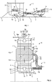
La
L'ensemble des satellites 8 est maintenu par un châssis appelé porte-satellites 10. Chaque satellite 8 tourne autour de son propre axe Y, et engrène avec la couronne 9.The set of
En sortie nous avons :
- ▪ Dans cette configuration épicycloïdale, l'ensemble des
satellites 8 entraine en rotation le porte-satellite 10 autour de l'axe X de la turbomachine. La couronne est fixée au cartermoteur ou stator 5 via un porte-couronne 12 et le porte-satellites 10 est fixé à l'arbre de soufflante 4. - ▪ Dans une autre configuration planétaire, l'ensemble des
satellites 8 est maintenu par un porte-satellites 10 qui est fixé au cartermoteur ou stator 5. Chaque satellite entraine la couronne qui est rapportée à l'arbre de soufflante 4 via un porte-couronne 12. - ▪ Dans une autre configuration différentielle, l'ensemble des
satellites 8 est maintenu par un porte-satellites 10 qui est relié à un premier arbre de soufflante 5. Chaque satellite entraine la couronne qui est rapportée à un second arbre de soufflante contrarotatif 4 via un porte-couronne 12.
- ▪ In this epicyclic configuration, the set of
planet wheels 8 drives theplanet carrier 10 in rotation around the X axis of the turbomachine. The ring gear is fixed to the motor casing orstator 5 via aring gear carrier 12 and theplanet gear carrier 10 is fixed to the fan shaft 4. - ▪ In another planetary configuration, all of the
planet gear 8 is held by aplanet gear carrier 10 which is fixed to the motor housing orstator 5. Each planet gear drives the ring gear which is attached to the fan shaft 4 via a carrier.crown 12. - ▪ In another differential configuration, all of the
planet gear 8 is held by aplanet carrier 10 which is connected to afirst fan shaft 5. Each planet gear drives the ring gear which is attached to a second contra-rotating fan shaft 4 via acrown holder 12.
Chaque satellite 8 est monté libre en rotation à l'aide d'un palier 11, par exemple de type roulement ou palier hydrodynamique. Chaque palier 11 est monté sur un des axes 10b du porte-satellites 10 et tous les axes sont positionnés les uns par rapport aux autres à l'aide d'un ou plusieurs châssis structurels 10a du porte-satellites 10. Il existe un nombre d'axes 10b et de paliers 11 égal au nombre de satellites. Pour des raisons de fonctionnement, de montage, de fabrication, de contrôle, de réparation ou de rechange, les axes 10b et le châssis 10a peuvent être séparés en plusieurs pièces.Each
Pour les mêmes raisons citées précédemment, la denture d'un satellite peut être séparée en plusieurs hélices ou dents présentant chacun un plan médian P, P'. Dans notre exemple, nous détaillons le fonctionnement d'un réducteur dont chaque satellite comprend deux séries de dents en chevron coopérant avec une couronne séparée en deux demi-couronnes:
- ▪ Une demi-
couronne amont 9a constituée d'une jante 9aa et d'une demi-bride de fixation 9ab. Sur la jante 9aa se trouve l'hélice avant engrenée avec une hélice de ladenture 8d de chaquesatellite 8. L'hélice de ladenture 8d engrène également avec celle du solaire 7. - ▪ Une demi-
couronne aval 9b constituée d'une jante 9ba et d'une demi-bride de fixation 9bb. Sur la jante 9ba se trouve l'hélice arrière engrenée avec une hélice de ladenture 8d de chaquesatellite 8. L'hélice de ladenture 8d engrène également avec celle du solaire 7.
- ▪ An upstream half-
ring 9a consisting of a rim 9aa and a fixing half-flange 9ab. On the rim 9aa is the front propeller meshed with a propeller of theteeth 8d of eachsatellite 8. The propeller of theteeth 8d also meshes with that of thesun 7. - ▪ A downstream half-
ring 9b made up of a rim 9ba and a fixing half-flange 9bb. On the rim 9ba is the rear propeller meshed with a propeller of theteeth 8d of eachsatellite 8. The propeller of theteeth 8d also meshes with that of thesun 7.
Si les largeurs d'hélice varient entre le solaire 7, les satellites 8 et la couronne 9 à cause des recouvrements de denture, elles sont toutes centrées sur un plan médian P pour les dents amont et sur un autre plan médian P' pour les dents aval.If the helix widths vary between solar 7,
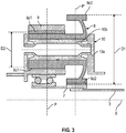
La
La demi-bride de fixation 9ab de la couronne amont 9a et la demi-bride de fixation 9bb de la couronne aval 9b forment la bride de fixation 9c de la couronne. La couronne 9 est fixée à un porte-couronne en assemblant la bride de fixation 9c de la couronne et la bride de fixation 12a du porte-couronne à l'aide d'un montage boulonné par exemple.The fixing half-flange 9ab of the
Les flèches de la
La
Dans cette
La denture 8d1 d'engrènement avec la couronne 9 a un diamètre moyen noté D2 et est situé dans un plan médian P. La denture 8d2 d'engrènement avec le solaire 7 a un diamètre moyen noté D1 et est situé dans un autre plan médian P'. Les plans médians P, P' sont parallèles entre eux et perpendiculaires à l'axe X. Le diamètre D2 est inférieur au diamètre D1. Enfin, chaque denture 8d1, 8d2 comprend ici une seule hélice.The gear 8d1 meshing with the
Comme évoqué dans ce qui précède, cette architecture « double étage » génère des moments non négligeables au niveau des satellites 8.As mentioned above, this “double-stage” architecture generates significant moments at the level of the
La présente invention propose de résoudre ce problème grâce à des satellites à double étage et à dentures symétriques, un mode préféré de réalisation de l'invention étant représenté aux
Le réducteur 60 des
- un solaire 70 ayant un axe de rotation X,
une couronne 90 qui s'étend autour du solaire et qui est configurée pour être immobile en rotation autour de l'axe X, et- des
satellites 80 qui sont engrenés avec le solaire 70 et la couronne 90 et qui sont maintenus par un porte-satellites 100 qui est configuré pour être mobile en rotation autour de l'axe X.
- a solar 70 having an axis of rotation X,
- a
ring 90 which extends around the solar and which is configured to be stationary in rotation around the X axis, and -
satellites 80 which are meshed with solar 70 andcrown 90 and which are held by aplanet carrier 100 which is configured to be movable in rotation about the X axis.
On définit le plan H comme étant un plan médian perpendiculaire à l'axe X et passant sensiblement au milieu du réducteur 60 (
Le solaire 70 comprend des cannelures internes 70a d'accouplement avec l'arbre BP 30 ainsi qu'une denture externe 70b d'engrènement avec les satellites 80. La denture 70b présente deux séries de dents adjacentes en chevron, séparées l'une de l'autre par une rainure annulaire 72 orientée radialement vers l'extérieur. La denture 70b est symétrique par rapport au plan H, ses dents étant situées de part et d'autre du plan H qui passe par la rainure 72.The solar 70 comprises
La couronne 90 est formée par deux anneaux indépendants 90a, 90b et comprend une denture qui est séparée en deux séries de dents 90d1, 90d2 en chevron portées respectivement par les deux anneaux.The
Les anneaux 90a, 90b sont disposés de manière symétrique par rapport au plan H qui s'étend donc entre ces anneaux. Les anneaux sont reliés et fixés à un porte-couronne 120 par l'intermédiaire de flasques annulaires 122 de liaison. Les flasques 122 sont indépendants l'un de l'autre, chaque flasque ayant en demi section axiale une forme générale en S lui procurant une certaine souplesse radiale par déformation élastique en fonctionnement. Chaque anneau 90a, 90b s'étend autour de l'axe X et est fixé au flasque 122 correspondant par sa périphérie externe. Sa périphérie interne comprend une des dents 90d1, 90d2.The
Dans l'exemple représenté qui n'est pas limitatif, le porte couronne 120 a une forme générale annulaire autour de l'axe X et plus particulièrement biconique. Il comprend ainsi un premier tronçon amont ou à gauche sur le dessin, avec une extrémité amont de plus petit diamètre, et une extrémité aval de plus grand diamètre qui est reliée à l'extrémité amont de plus grand diamètre de l'autre tronçon, aval ou à droite sur le dessin. Les extrémités de plus grand diamètre des tronçons sont donc reliées entre elles, et leurs extrémités de plus petits diamètres forment les extrémités axiales du porte-couronne.In the example shown which is not limiting, the
L'extrémité amont du porte-couronne 120 s'étend autour du porte-satellites 100 ou d'un arbre relié à ce porte-satellites, et est centré et guidé en rotation sur le porte-satellite ou l'arbre par l'intermédiaire d'au moins un palier 124. De la même façon, l'extrémité aval du porte-couronne 120 s'étend autour du porte-satellites 100 ou d'un arbre relié à ce porte-satellites, et est centré et guidé en rotation sur le porte-satellite ou l'arbre par l'intermédiaire d'au moins un autre palier 126.The upstream end of the
Comme c'est le cas de la couronne 90, le porte-couronne 120 présente une symétrie par rapport au plan H qui coupe le porte-couronne en son milieu et passe donc par les extrémités de plus grand diamètre des tronçons précités. Chaque satellite 80 comporte une première denture 82 de diamètre moyen D1 pour l'engrènement avec le solaire 70, et une seconde denture 84 de diamètre moyen D2, différent de D1 et en particulier inférieur à D1, pour l'engrènement avec la couronne 90. Les diamètres moyens sont mesurés depuis l'axe Y de chaque satellite et représente la moyenne entre le diamètre maximal et le diamètre minimal d'une denture de ce satellite.As is the case with the
Chaque satellite 80 comprend un corps cylindrique 86 et un voile annulaire 88 s'étendant sensiblement radialement vers l'extérieur depuis le milieu de ce corps 86. La denture 84 est séparée en deux séries de dents 84d1, 84d2 en chevron qui sont situées respectivement sur les extrémités axiales du corps 86. La denture 82 comprend deux séries de dents 82d1, 82d2 en chevron qui sont situées à la périphérie externe du voile 88 et qui sont séparées l'une de l'autre par une rainure annulaire 89 débouchant radialement vers l'extérieur par rapport à l'axe Y.Each
La denture 82 est traversée en son milieu par le plan H qui passe par la rainure 89, les dents 82d1, 82d2 étant donc disposées de part et d'autre du plan H. Les dents 84d1, 84d2 sont également disposées de manière symétrique par rapport au plan H.The
La denture 82 et la périphérie externe du voile 88 ont une dimension axiale qui est inférieure à la distance axiale entre les anneaux 90a, 90b, ainsi qu'entre les flasques 122, de façon à ce que chaque satellite 80 puisse librement tourner dans le porte-couronne 120 et entre les anneaux 90a, 90b et les flasques 122.The
La solution propose ainsi de « symétriser » des dentures des satellites du réducteur afin de symétriser les efforts axiaux ainsi que les moments auxquels les satellites sont soumis en fonctionnement. Cette solution permet en outre de gagner en longueur ou dimension axiale vis-à-vis d'une denture chevron par disparition de la gorge inter-denture de l'étage d'engrènement avec la couronne.The solution thus proposes to "symmetrize" the teeth of the gear wheels in order to symmetrize the axial forces as well as the moments. to which the satellites are subjected in operation. This solution also makes it possible to gain in length or axial dimension vis-à-vis a chevron set of teeth by disappearance of the inter-tooth groove of the stage of engagement with the ring gear.
Cette solution est notamment compatible :
- d'une utilisation « épicycloïdale » à porte-satellites tournant et couronne fixe ;
- d'une utilisation « planétaire » à couronne tournante et porte-satellites fixe
- d'une utilisation « différentiel » à couronne et porte-satellites tournants.
- de paliers à éléments roulants et également de paliers hydrodynamiques
- d'un porte-satellite monobloc ou en plusieurs parties.
- "epicyclic" use with rotating planet gear and fixed crown;
- a "planetary" use with rotating crown and fixed planet carrier
- a "differential" use with crown wheel and rotating planet carriers.
- rolling element bearings and also hydrodynamic bearings
- a one-piece or multi-part planet gear carrier.
Claims (10)
caractérisé en ce que les première et seconde dentures (82, 84) de chaque satellite (80) présentent une symétrie par rapport à un plan (H) perpendiculaire audit axe (X) et passant au milieu du satellite (80),
et en ce que le chevron de la première denture est formé par des dents amont (82d1) de la première denture (82) séparées de dents aval (82d2) de la première denture (82) en étant disposées de part et d'autre du plan (H), et les dents amont (84d1) de la seconde denture (84) sont séparées des dents aval (84d2) de la seconde denture (84) par la première denture (82).
characterized in that the first and second teeth (82, 84) of each satellite (80) have a symmetry with respect to a plane (H) perpendicular to said axis (X) and passing through the middle of the satellite (80),
and in that the chevron of the first set of teeth is formed by upstream teeth (82d1) of the first set of teeth (82) separated from downstream teeth (82d2) of the first set of teeth (82) being arranged on either side of the plane (H), and the upstream teeth (84d1) of the second set of teeth (84) are separated from the downstream teeth (84d2) of the second set of teeth (84) by the first set of teeth (82).
Applications Claiming Priority (1)
| Application Number | Priority Date | Filing Date | Title |
|---|---|---|---|
| FR1904052A FR3095251B1 (en) | 2019-04-16 | 2019-04-16 | AIRCRAFT TURBOMACHINE MECHANICAL REDUCER |
Publications (2)
| Publication Number | Publication Date |
|---|---|
| EP3726031A1 true EP3726031A1 (en) | 2020-10-21 |
| EP3726031B1 EP3726031B1 (en) | 2022-01-12 |
Family
ID=67262735
Family Applications (1)
| Application Number | Title | Priority Date | Filing Date |
|---|---|---|---|
| EP20169893.3A Active EP3726031B1 (en) | 2019-04-16 | 2020-04-16 | Mechanical gear for aircraft turbine engine |
Country Status (5)
| Country | Link |
|---|---|
| US (1) | US11339725B2 (en) |
| EP (1) | EP3726031B1 (en) |
| JP (1) | JP2020176721A (en) |
| CN (1) | CN111828174B (en) |
| FR (1) | FR3095251B1 (en) |
Cited By (10)
| Publication number | Priority date | Publication date | Assignee | Title |
|---|---|---|---|---|
| EP3825575A1 (en) * | 2019-11-20 | 2021-05-26 | Raytheon Technologies Corporation | Geared architecture for gas turbine engine |
| IT202000014206A1 (en) * | 2020-06-15 | 2021-12-15 | Ge Avio Srl | TURBOMACHINES AND PLANETARY GEAR SETS WITH SYMMETRICAL COMPOUND ARRANGEMENT |
| EP3922831A1 (en) | 2020-06-11 | 2021-12-15 | Safran Transmission Systems | Mechanical gear for aircraft turbine engine |
| EP3995681A1 (en) | 2020-11-10 | 2022-05-11 | Safran Transmission Systems | Mechanical gear for aircraft turbine engine |
| FR3116096A1 (en) * | 2020-11-12 | 2022-05-13 | Safran Transmission Systems | AIRCRAFT TURBOMACHINE MECHANICAL REDUCER |
| IT202100028244A1 (en) * | 2021-11-05 | 2023-05-05 | Ge Avio Srl | COMPOUND SYMMETRICAL GEAR BOX FOR A TURBOMACHINE |
| US11643972B2 (en) | 2020-06-15 | 2023-05-09 | Ge Avio S.R.L. | Turbomachines and epicyclic gear assemblies with symmetrical compound arrangement |
| FR3136532A1 (en) | 2022-06-13 | 2023-12-15 | Safran Transmission Systems | Compact gear train for turbomachine reducer |
| FR3136531A1 (en) | 2022-06-13 | 2023-12-15 | Safran Transmission Systems | Compact gear train for turbomachine reducer |
| US11971085B2 (en) | 2022-07-22 | 2024-04-30 | Ge Avio S.R.L. | Gearbox assembly |
Families Citing this family (8)
| Publication number | Priority date | Publication date | Assignee | Title |
|---|---|---|---|---|
| US11415064B2 (en) * | 2019-11-20 | 2022-08-16 | Raytheon Technologies Corporation | Geared architecture for gas turbine engine |
| IT202000002272A1 (en) * | 2020-02-05 | 2021-08-05 | Ge Avio Srl | GEAR BOX FOR AN ENGINE |
| US11542829B2 (en) * | 2020-05-06 | 2023-01-03 | Ge Avio S.R.L. | Turbomachines and epicyclic gear assemblies with axially offset sun and ring gears |
| FR3111400B1 (en) * | 2020-06-11 | 2022-05-13 | Safran Trans Systems | AIRCRAFT TURBOMACHINE MECHANICAL REDUCER |
| IT202100015386A1 (en) * | 2021-06-11 | 2022-12-11 | Ge Avio Srl | TURBOMACHINES AND PLANETARY GEAR SETS WITH LUBRICATION CHANNELS |
| US11873767B2 (en) * | 2021-10-22 | 2024-01-16 | Ge Avio S.R.L. | Gearbox configurations for clockwise and counterclockwise propeller rotation |
| FR3134867A1 (en) | 2022-04-22 | 2023-10-27 | Safran Transmission Systems | MECHANICAL AIRCRAFT TURBOMACHINE REDUCER |
| US11787551B1 (en) * | 2022-10-06 | 2023-10-17 | Archer Aviation, Inc. | Vertical takeoff and landing aircraft electric engine configuration |
Citations (8)
| Publication number | Priority date | Publication date | Assignee | Title |
|---|---|---|---|---|
| DE814981C (en) * | 1949-05-01 | 1951-09-27 | Wilhelm Dipl-Ing Stoeckicht | Planetary gear with herringbone teeth |
| US3188888A (en) | 1958-01-31 | 1965-06-15 | Renk Ag Zahnraeder | Epicyclic transmission |
| WO2010092263A1 (en) | 2009-02-16 | 2010-08-19 | Snecma | Lubrication and cooling of a reduction gear with epicyclic gear train |
| US20130192264A1 (en) * | 2012-01-31 | 2013-08-01 | Michael E. McCune | Turbine engine gearbox |
| FR2987416A1 (en) | 2012-02-23 | 2013-08-30 | Snecma | DEVICE FOR LUBRICATING AN EPICYCLOIDAL REDUCER. |
| FR3008462A1 (en) | 2013-07-10 | 2015-01-16 | Hispano Suiza Sa | INTEGRATION OF A GEAR TRAIN IN A DRIVE GEAR FOR DRIVE HOUSING FOR TURBOMACHINE |
| FR3041054A1 (en) | 2015-09-15 | 2017-03-17 | Hispano-Suiza | OIL SUPPLY DEVICE FOR AN EPICYCLOIDAL TRAIN REDUCER. |
| EP3361122A1 (en) * | 2017-02-10 | 2018-08-15 | Pratt & Whitney Canada Corp. | Planetary gearbox for gas turbine engine |
Family Cites Families (8)
| Publication number | Priority date | Publication date | Assignee | Title |
|---|---|---|---|---|
| US3307433A (en) * | 1963-12-02 | 1967-03-07 | Curtiss Wright Corp | Compound planetary speed reducer with adjustable gearing |
| US3640150A (en) * | 1970-06-25 | 1972-02-08 | Curtiss Wright Corp | Power driven actuator of the compound planetary gear type |
| US4742730A (en) * | 1982-09-30 | 1988-05-10 | The Boeing Company | Failsafe rotary actuator |
| DE10254527A1 (en) * | 2002-11-22 | 2004-06-09 | Multibrid Entwicklungsges. Mbh | Process for low-loss torque transmission in planetary gears |
| US8622869B2 (en) * | 2011-12-28 | 2014-01-07 | George Dimitri Mourani | Drive train transmission |
| EP2610461B1 (en) * | 2011-12-30 | 2019-10-23 | United Technologies Corporation | Turbine engine |
| FR2987417B1 (en) * | 2012-02-23 | 2014-03-28 | Snecma | DEVICE FOR RECOVERING THE LUBRICATING OIL OF AN EPICYCLOIDAL REDUCER. |
| WO2018035190A1 (en) * | 2016-08-16 | 2018-02-22 | Sikorsky Aircraft Corporation | Asymmetric gear teeth |
-
2019
- 2019-04-16 FR FR1904052A patent/FR3095251B1/en not_active Expired - Fee Related
-
2020
- 2020-04-14 JP JP2020072120A patent/JP2020176721A/en active Pending
- 2020-04-14 US US16/848,642 patent/US11339725B2/en active Active
- 2020-04-15 CN CN202010296519.4A patent/CN111828174B/en active Active
- 2020-04-16 EP EP20169893.3A patent/EP3726031B1/en active Active
Patent Citations (8)
| Publication number | Priority date | Publication date | Assignee | Title |
|---|---|---|---|---|
| DE814981C (en) * | 1949-05-01 | 1951-09-27 | Wilhelm Dipl-Ing Stoeckicht | Planetary gear with herringbone teeth |
| US3188888A (en) | 1958-01-31 | 1965-06-15 | Renk Ag Zahnraeder | Epicyclic transmission |
| WO2010092263A1 (en) | 2009-02-16 | 2010-08-19 | Snecma | Lubrication and cooling of a reduction gear with epicyclic gear train |
| US20130192264A1 (en) * | 2012-01-31 | 2013-08-01 | Michael E. McCune | Turbine engine gearbox |
| FR2987416A1 (en) | 2012-02-23 | 2013-08-30 | Snecma | DEVICE FOR LUBRICATING AN EPICYCLOIDAL REDUCER. |
| FR3008462A1 (en) | 2013-07-10 | 2015-01-16 | Hispano Suiza Sa | INTEGRATION OF A GEAR TRAIN IN A DRIVE GEAR FOR DRIVE HOUSING FOR TURBOMACHINE |
| FR3041054A1 (en) | 2015-09-15 | 2017-03-17 | Hispano-Suiza | OIL SUPPLY DEVICE FOR AN EPICYCLOIDAL TRAIN REDUCER. |
| EP3361122A1 (en) * | 2017-02-10 | 2018-08-15 | Pratt & Whitney Canada Corp. | Planetary gearbox for gas turbine engine |
Cited By (19)
| Publication number | Priority date | Publication date | Assignee | Title |
|---|---|---|---|---|
| US11215122B2 (en) | 2019-11-20 | 2022-01-04 | Raytheon Technologies Corporation | Geared architecture for gas turbine engine |
| EP3825575A1 (en) * | 2019-11-20 | 2021-05-26 | Raytheon Technologies Corporation | Geared architecture for gas turbine engine |
| EP3922831A1 (en) | 2020-06-11 | 2021-12-15 | Safran Transmission Systems | Mechanical gear for aircraft turbine engine |
| FR3111390A1 (en) * | 2020-06-11 | 2021-12-17 | Safran Transmission Systems | AIRCRAFT TURBOMACHINE MECHANICAL REDUCER |
| US11591972B2 (en) | 2020-06-11 | 2023-02-28 | Safran Transmission Systems | Mechanical gearbox for aircraft turbomachine |
| US11643972B2 (en) | 2020-06-15 | 2023-05-09 | Ge Avio S.R.L. | Turbomachines and epicyclic gear assemblies with symmetrical compound arrangement |
| IT202000014206A1 (en) * | 2020-06-15 | 2021-12-15 | Ge Avio Srl | TURBOMACHINES AND PLANETARY GEAR SETS WITH SYMMETRICAL COMPOUND ARRANGEMENT |
| EP3995681A1 (en) | 2020-11-10 | 2022-05-11 | Safran Transmission Systems | Mechanical gear for aircraft turbine engine |
| FR3116095A1 (en) * | 2020-11-10 | 2022-05-13 | Safran Transmission Systems | AIRCRAFT TURBOMACHINE MECHANICAL REDUCER |
| US11867259B2 (en) | 2020-11-10 | 2024-01-09 | Safran Transmission Systems | Mechanical gearbox for an aircraft turbomachine |
| EP4001619A1 (en) | 2020-11-12 | 2022-05-25 | Safran Transmission Systems | Mechanical gear for aircraft turbine engine |
| US11739829B2 (en) | 2020-11-12 | 2023-08-29 | Safran Transmission Systems | Mechanical reduction gear for an aircraft turbomachine |
| FR3116096A1 (en) * | 2020-11-12 | 2022-05-13 | Safran Transmission Systems | AIRCRAFT TURBOMACHINE MECHANICAL REDUCER |
| IT202100028244A1 (en) * | 2021-11-05 | 2023-05-05 | Ge Avio Srl | COMPOUND SYMMETRICAL GEAR BOX FOR A TURBOMACHINE |
| FR3136532A1 (en) | 2022-06-13 | 2023-12-15 | Safran Transmission Systems | Compact gear train for turbomachine reducer |
| FR3136531A1 (en) | 2022-06-13 | 2023-12-15 | Safran Transmission Systems | Compact gear train for turbomachine reducer |
| WO2023242506A1 (en) | 2022-06-13 | 2023-12-21 | Safran Transmission Systems | Compact gear train for turbomachine reducer |
| WO2023242507A1 (en) | 2022-06-13 | 2023-12-21 | Safran Transmission Systems | Compact gear train for turbomachine reducer |
| US11971085B2 (en) | 2022-07-22 | 2024-04-30 | Ge Avio S.R.L. | Gearbox assembly |
Also Published As
| Publication number | Publication date |
|---|---|
| JP2020176721A (en) | 2020-10-29 |
| US20200332721A1 (en) | 2020-10-22 |
| FR3095251A1 (en) | 2020-10-23 |
| CN111828174B (en) | 2023-11-21 |
| CN111828174A (en) | 2020-10-27 |
| US11339725B2 (en) | 2022-05-24 |
| EP3726031B1 (en) | 2022-01-12 |
| FR3095251B1 (en) | 2021-05-07 |
Similar Documents
| Publication | Publication Date | Title |
|---|---|---|
| EP3726031B1 (en) | Mechanical gear for aircraft turbine engine | |
| EP3922886B1 (en) | Mechanical gear for aircraft turbine engine | |
| EP4001619B1 (en) | Mechanical gear for aircraft turbine engine | |
| EP3922831B1 (en) | Mechanical gear for aircraft turbine engine | |
| EP3705705B1 (en) | Mechanical gear of an aircraft turbine engine | |
| EP3995681A1 (en) | Mechanical gear for aircraft turbine engine | |
| EP4108899A1 (en) | Planet carrier for a speed reducer of an aircraft turbine engine | |
| EP3892895A1 (en) | Mechanical gear for aircraft turbine engine | |
| EP3992494B1 (en) | Mechanical gear for aircraft turbine engine | |
| EP3982009B1 (en) | Mechanical gear for aircraft turbine engine | |
| EP4033086B1 (en) | Turbine engine for aircraft with triple flow provided with a power transmission module | |
| EP4339484A1 (en) | Aircraft turbine engine with mechanical reduction gear | |
| EP4336070A1 (en) | Drive assembly for a mechanical reduction gear of an aircraft turbine engine | |
| EP4265940A1 (en) | Mechanical reduction gear for an aircraft turbine engine | |
| EP4093992A1 (en) | Planet carrier for a mechanical reduction gear of an aircraft turbomachine | |
| EP4242489A1 (en) | Mechanical reduction gear for an aircraft turbine engine | |
| EP4339098A1 (en) | Device for driving at least one wheel of an aircraft landing gear | |
| EP4290097A1 (en) | Planet carrier for a mechanical gearbox of an aircraft turbomachine | |
| EP4303468A1 (en) | Sun gear for a reduction gearbox of an aircraft turbine engine | |
| EP4151846A1 (en) | Aircraft turbine engine | |
| EP4123190A1 (en) | Mechanical gearbox for a longitudinal axis gas turbine engine | |
| FR3139870A1 (en) | TRANSMISSION ASSEMBLY FOR AN AIRCRAFT TURBOMACHINE MECHANICAL REDUCER | |
| EP3974677A1 (en) | Improved reducer for supporting a crown |
Legal Events
| Date | Code | Title | Description |
|---|---|---|---|
| PUAI | Public reference made under article 153(3) epc to a published international application that has entered the european phase |
Free format text: ORIGINAL CODE: 0009012 |
|
| STAA | Information on the status of an ep patent application or granted ep patent |
Free format text: STATUS: REQUEST FOR EXAMINATION WAS MADE |
|
| 17P | Request for examination filed |
Effective date: 20200416 |
|
| AK | Designated contracting states |
Kind code of ref document: A1 Designated state(s): AL AT BE BG CH CY CZ DE DK EE ES FI FR GB GR HR HU IE IS IT LI LT LU LV MC MK MT NL NO PL PT RO RS SE SI SK SM TR |
|
| AX | Request for extension of the european patent |
Extension state: BA ME |
|
| GRAP | Despatch of communication of intention to grant a patent |
Free format text: ORIGINAL CODE: EPIDOSNIGR1 |
|
| STAA | Information on the status of an ep patent application or granted ep patent |
Free format text: STATUS: GRANT OF PATENT IS INTENDED |
|
| RIC1 | Information provided on ipc code assigned before grant |
Ipc: F02C 7/36 20060101AFI20210719BHEP Ipc: F16H 1/28 20060101ALN20210719BHEP |
|
| INTG | Intention to grant announced |
Effective date: 20210812 |
|
| GRAS | Grant fee paid |
Free format text: ORIGINAL CODE: EPIDOSNIGR3 |
|
| GRAA | (expected) grant |
Free format text: ORIGINAL CODE: 0009210 |
|
| STAA | Information on the status of an ep patent application or granted ep patent |
Free format text: STATUS: THE PATENT HAS BEEN GRANTED |
|
| AK | Designated contracting states |
Kind code of ref document: B1 Designated state(s): AL AT BE BG CH CY CZ DE DK EE ES FI FR GB GR HR HU IE IS IT LI LT LU LV MC MK MT NL NO PL PT RO RS SE SI SK SM TR |
|
| REG | Reference to a national code |
Ref country code: GB Ref legal event code: FG4D Free format text: NOT ENGLISH |
|
| REG | Reference to a national code |
Ref country code: CH Ref legal event code: EP |
|
| REG | Reference to a national code |
Ref country code: DE Ref legal event code: R096 Ref document number: 602020001583 Country of ref document: DE |
|
| REG | Reference to a national code |
Ref country code: IE Ref legal event code: FG4D Free format text: LANGUAGE OF EP DOCUMENT: FRENCH |
|
| REG | Reference to a national code |
Ref country code: AT Ref legal event code: REF Ref document number: 1462538 Country of ref document: AT Kind code of ref document: T Effective date: 20220215 |
|
| REG | Reference to a national code |
Ref country code: LT Ref legal event code: MG9D |
|
| REG | Reference to a national code |
Ref country code: NL Ref legal event code: MP Effective date: 20220112 |
|
| REG | Reference to a national code |
Ref country code: AT Ref legal event code: MK05 Ref document number: 1462538 Country of ref document: AT Kind code of ref document: T Effective date: 20220112 |
|
| PG25 | Lapsed in a contracting state [announced via postgrant information from national office to epo] |
Ref country code: NL Free format text: LAPSE BECAUSE OF FAILURE TO SUBMIT A TRANSLATION OF THE DESCRIPTION OR TO PAY THE FEE WITHIN THE PRESCRIBED TIME-LIMIT Effective date: 20220112 |
|
| PG25 | Lapsed in a contracting state [announced via postgrant information from national office to epo] |
Ref country code: SE Free format text: LAPSE BECAUSE OF FAILURE TO SUBMIT A TRANSLATION OF THE DESCRIPTION OR TO PAY THE FEE WITHIN THE PRESCRIBED TIME-LIMIT Effective date: 20220112 Ref country code: RS Free format text: LAPSE BECAUSE OF FAILURE TO SUBMIT A TRANSLATION OF THE DESCRIPTION OR TO PAY THE FEE WITHIN THE PRESCRIBED TIME-LIMIT Effective date: 20220112 Ref country code: PT Free format text: LAPSE BECAUSE OF FAILURE TO SUBMIT A TRANSLATION OF THE DESCRIPTION OR TO PAY THE FEE WITHIN THE PRESCRIBED TIME-LIMIT Effective date: 20220512 Ref country code: NO Free format text: LAPSE BECAUSE OF FAILURE TO SUBMIT A TRANSLATION OF THE DESCRIPTION OR TO PAY THE FEE WITHIN THE PRESCRIBED TIME-LIMIT Effective date: 20220412 Ref country code: LT Free format text: LAPSE BECAUSE OF FAILURE TO SUBMIT A TRANSLATION OF THE DESCRIPTION OR TO PAY THE FEE WITHIN THE PRESCRIBED TIME-LIMIT Effective date: 20220112 Ref country code: HR Free format text: LAPSE BECAUSE OF FAILURE TO SUBMIT A TRANSLATION OF THE DESCRIPTION OR TO PAY THE FEE WITHIN THE PRESCRIBED TIME-LIMIT Effective date: 20220112 Ref country code: ES Free format text: LAPSE BECAUSE OF FAILURE TO SUBMIT A TRANSLATION OF THE DESCRIPTION OR TO PAY THE FEE WITHIN THE PRESCRIBED TIME-LIMIT Effective date: 20220112 Ref country code: BG Free format text: LAPSE BECAUSE OF FAILURE TO SUBMIT A TRANSLATION OF THE DESCRIPTION OR TO PAY THE FEE WITHIN THE PRESCRIBED TIME-LIMIT Effective date: 20220412 |
|
| PG25 | Lapsed in a contracting state [announced via postgrant information from national office to epo] |
Ref country code: PL Free format text: LAPSE BECAUSE OF FAILURE TO SUBMIT A TRANSLATION OF THE DESCRIPTION OR TO PAY THE FEE WITHIN THE PRESCRIBED TIME-LIMIT Effective date: 20220112 Ref country code: LV Free format text: LAPSE BECAUSE OF FAILURE TO SUBMIT A TRANSLATION OF THE DESCRIPTION OR TO PAY THE FEE WITHIN THE PRESCRIBED TIME-LIMIT Effective date: 20220112 Ref country code: GR Free format text: LAPSE BECAUSE OF FAILURE TO SUBMIT A TRANSLATION OF THE DESCRIPTION OR TO PAY THE FEE WITHIN THE PRESCRIBED TIME-LIMIT Effective date: 20220413 Ref country code: FI Free format text: LAPSE BECAUSE OF FAILURE TO SUBMIT A TRANSLATION OF THE DESCRIPTION OR TO PAY THE FEE WITHIN THE PRESCRIBED TIME-LIMIT Effective date: 20220112 Ref country code: AT Free format text: LAPSE BECAUSE OF FAILURE TO SUBMIT A TRANSLATION OF THE DESCRIPTION OR TO PAY THE FEE WITHIN THE PRESCRIBED TIME-LIMIT Effective date: 20220112 |
|
| PG25 | Lapsed in a contracting state [announced via postgrant information from national office to epo] |
Ref country code: IS Free format text: LAPSE BECAUSE OF FAILURE TO SUBMIT A TRANSLATION OF THE DESCRIPTION OR TO PAY THE FEE WITHIN THE PRESCRIBED TIME-LIMIT Effective date: 20220512 |
|
| REG | Reference to a national code |
Ref country code: DE Ref legal event code: R097 Ref document number: 602020001583 Country of ref document: DE |
|
| PG25 | Lapsed in a contracting state [announced via postgrant information from national office to epo] |
Ref country code: SM Free format text: LAPSE BECAUSE OF FAILURE TO SUBMIT A TRANSLATION OF THE DESCRIPTION OR TO PAY THE FEE WITHIN THE PRESCRIBED TIME-LIMIT Effective date: 20220112 Ref country code: SK Free format text: LAPSE BECAUSE OF FAILURE TO SUBMIT A TRANSLATION OF THE DESCRIPTION OR TO PAY THE FEE WITHIN THE PRESCRIBED TIME-LIMIT Effective date: 20220112 Ref country code: RO Free format text: LAPSE BECAUSE OF FAILURE TO SUBMIT A TRANSLATION OF THE DESCRIPTION OR TO PAY THE FEE WITHIN THE PRESCRIBED TIME-LIMIT Effective date: 20220112 Ref country code: EE Free format text: LAPSE BECAUSE OF FAILURE TO SUBMIT A TRANSLATION OF THE DESCRIPTION OR TO PAY THE FEE WITHIN THE PRESCRIBED TIME-LIMIT Effective date: 20220112 Ref country code: DK Free format text: LAPSE BECAUSE OF FAILURE TO SUBMIT A TRANSLATION OF THE DESCRIPTION OR TO PAY THE FEE WITHIN THE PRESCRIBED TIME-LIMIT Effective date: 20220112 Ref country code: CZ Free format text: LAPSE BECAUSE OF FAILURE TO SUBMIT A TRANSLATION OF THE DESCRIPTION OR TO PAY THE FEE WITHIN THE PRESCRIBED TIME-LIMIT Effective date: 20220112 |
|
| PLBE | No opposition filed within time limit |
Free format text: ORIGINAL CODE: 0009261 |
|
| STAA | Information on the status of an ep patent application or granted ep patent |
Free format text: STATUS: NO OPPOSITION FILED WITHIN TIME LIMIT |
|
| PG25 | Lapsed in a contracting state [announced via postgrant information from national office to epo] |
Ref country code: AL Free format text: LAPSE BECAUSE OF FAILURE TO SUBMIT A TRANSLATION OF THE DESCRIPTION OR TO PAY THE FEE WITHIN THE PRESCRIBED TIME-LIMIT Effective date: 20220112 |
|
| 26N | No opposition filed |
Effective date: 20221013 |
|
| REG | Reference to a national code |
Ref country code: BE Ref legal event code: MM Effective date: 20220430 |
|
| PG25 | Lapsed in a contracting state [announced via postgrant information from national office to epo] |
Ref country code: MC Free format text: LAPSE BECAUSE OF FAILURE TO SUBMIT A TRANSLATION OF THE DESCRIPTION OR TO PAY THE FEE WITHIN THE PRESCRIBED TIME-LIMIT Effective date: 20220112 Ref country code: LU Free format text: LAPSE BECAUSE OF NON-PAYMENT OF DUE FEES Effective date: 20220416 |
|
| PG25 | Lapsed in a contracting state [announced via postgrant information from national office to epo] |
Ref country code: BE Free format text: LAPSE BECAUSE OF NON-PAYMENT OF DUE FEES Effective date: 20220430 Ref country code: SI Free format text: LAPSE BECAUSE OF FAILURE TO SUBMIT A TRANSLATION OF THE DESCRIPTION OR TO PAY THE FEE WITHIN THE PRESCRIBED TIME-LIMIT Effective date: 20220112 |
|
| PG25 | Lapsed in a contracting state [announced via postgrant information from national office to epo] |
Ref country code: IE Free format text: LAPSE BECAUSE OF NON-PAYMENT OF DUE FEES Effective date: 20220416 |
|
| PGFP | Annual fee paid to national office [announced via postgrant information from national office to epo] |
Ref country code: FR Payment date: 20230321 Year of fee payment: 4 |
|
| PG25 | Lapsed in a contracting state [announced via postgrant information from national office to epo] |
Ref country code: IT Free format text: LAPSE BECAUSE OF FAILURE TO SUBMIT A TRANSLATION OF THE DESCRIPTION OR TO PAY THE FEE WITHIN THE PRESCRIBED TIME-LIMIT Effective date: 20220112 |
|
| PGFP | Annual fee paid to national office [announced via postgrant information from national office to epo] |
Ref country code: DE Payment date: 20230321 Year of fee payment: 4 |
|
| REG | Reference to a national code |
Ref country code: CH Ref legal event code: PL |
|
| PG25 | Lapsed in a contracting state [announced via postgrant information from national office to epo] |
Ref country code: LI Free format text: LAPSE BECAUSE OF NON-PAYMENT OF DUE FEES Effective date: 20230430 Ref country code: CH Free format text: LAPSE BECAUSE OF NON-PAYMENT OF DUE FEES Effective date: 20230430 |