EP3726025B1 - Modules de puissance dotés de roues de compresseur régénératif - Google Patents
Modules de puissance dotés de roues de compresseur régénératif Download PDFInfo
- Publication number
- EP3726025B1 EP3726025B1 EP19216265.9A EP19216265A EP3726025B1 EP 3726025 B1 EP3726025 B1 EP 3726025B1 EP 19216265 A EP19216265 A EP 19216265A EP 3726025 B1 EP3726025 B1 EP 3726025B1
- Authority
- EP
- European Patent Office
- Prior art keywords
- turbine
- compressor wheel
- regenerative
- air bearing
- compressor
- Prior art date
- Legal status (The legal status is an assumption and is not a legal conclusion. Google has not performed a legal analysis and makes no representation as to the accuracy of the status listed.)
- Active
Links
- 230000001172 regenerating effect Effects 0.000 title claims description 50
- 239000003570 air Substances 0.000 claims description 112
- 239000000446 fuel Substances 0.000 claims description 60
- 238000004891 communication Methods 0.000 claims description 32
- 239000012530 fluid Substances 0.000 claims description 31
- 239000007788 liquid Substances 0.000 claims description 14
- 238000000034 method Methods 0.000 claims description 14
- 239000012080 ambient air Substances 0.000 claims description 9
- 239000002826 coolant Substances 0.000 claims description 5
- 238000004804 winding Methods 0.000 claims description 5
- 238000001816 cooling Methods 0.000 claims description 4
- 230000008878 coupling Effects 0.000 claims description 3
- 238000010168 coupling process Methods 0.000 claims description 3
- 238000005859 coupling reaction Methods 0.000 claims description 3
- 239000007789 gas Substances 0.000 description 32
- 238000002485 combustion reaction Methods 0.000 description 8
- 239000007800 oxidant agent Substances 0.000 description 8
- 239000003350 kerosene Substances 0.000 description 4
- 230000001590 oxidative effect Effects 0.000 description 4
- IJGRMHOSHXDMSA-UHFFFAOYSA-N Atomic nitrogen Chemical compound N#N IJGRMHOSHXDMSA-UHFFFAOYSA-N 0.000 description 2
- 239000000284 extract Substances 0.000 description 2
- 241000238631 Hexapoda Species 0.000 description 1
- 238000010586 diagram Methods 0.000 description 1
- 239000002283 diesel fuel Substances 0.000 description 1
- 230000000694 effects Effects 0.000 description 1
- 238000007667 floating Methods 0.000 description 1
- 238000007689 inspection Methods 0.000 description 1
- 239000000314 lubricant Substances 0.000 description 1
- 238000013507 mapping Methods 0.000 description 1
- 239000000463 material Substances 0.000 description 1
- 238000005259 measurement Methods 0.000 description 1
- 238000012986 modification Methods 0.000 description 1
- 230000004048 modification Effects 0.000 description 1
- 229910052757 nitrogen Inorganic materials 0.000 description 1
- 238000010248 power generation Methods 0.000 description 1
- 238000005086 pumping Methods 0.000 description 1
- 239000007858 starting material Substances 0.000 description 1
Images


Classifications
-
- F—MECHANICAL ENGINEERING; LIGHTING; HEATING; WEAPONS; BLASTING
- F02—COMBUSTION ENGINES; HOT-GAS OR COMBUSTION-PRODUCT ENGINE PLANTS
- F02C—GAS-TURBINE PLANTS; AIR INTAKES FOR JET-PROPULSION PLANTS; CONTROLLING FUEL SUPPLY IN AIR-BREATHING JET-PROPULSION PLANTS
- F02C3/00—Gas-turbine plants characterised by the use of combustion products as the working fluid
- F02C3/04—Gas-turbine plants characterised by the use of combustion products as the working fluid having a turbine driving a compressor
- F02C3/08—Gas-turbine plants characterised by the use of combustion products as the working fluid having a turbine driving a compressor the compressor comprising at least one radial stage
-
- B—PERFORMING OPERATIONS; TRANSPORTING
- B64—AIRCRAFT; AVIATION; COSMONAUTICS
- B64C—AEROPLANES; HELICOPTERS
- B64C27/00—Rotorcraft; Rotors peculiar thereto
- B64C27/04—Helicopters
- B64C27/08—Helicopters with two or more rotors
-
- B—PERFORMING OPERATIONS; TRANSPORTING
- B64—AIRCRAFT; AVIATION; COSMONAUTICS
- B64U—UNMANNED AERIAL VEHICLES [UAV]; EQUIPMENT THEREFOR
- B64U50/00—Propulsion; Power supply
- B64U50/30—Supply or distribution of electrical power
- B64U50/33—Supply or distribution of electrical power generated by combustion engines
-
- F—MECHANICAL ENGINEERING; LIGHTING; HEATING; WEAPONS; BLASTING
- F01—MACHINES OR ENGINES IN GENERAL; ENGINE PLANTS IN GENERAL; STEAM ENGINES
- F01D—NON-POSITIVE DISPLACEMENT MACHINES OR ENGINES, e.g. STEAM TURBINES
- F01D15/00—Adaptations of machines or engines for special use; Combinations of engines with devices driven thereby
- F01D15/08—Adaptations for driving, or combinations with, pumps
-
- F—MECHANICAL ENGINEERING; LIGHTING; HEATING; WEAPONS; BLASTING
- F01—MACHINES OR ENGINES IN GENERAL; ENGINE PLANTS IN GENERAL; STEAM ENGINES
- F01D—NON-POSITIVE DISPLACEMENT MACHINES OR ENGINES, e.g. STEAM TURBINES
- F01D15/00—Adaptations of machines or engines for special use; Combinations of engines with devices driven thereby
- F01D15/10—Adaptations for driving, or combinations with, electric generators
-
- F—MECHANICAL ENGINEERING; LIGHTING; HEATING; WEAPONS; BLASTING
- F01—MACHINES OR ENGINES IN GENERAL; ENGINE PLANTS IN GENERAL; STEAM ENGINES
- F01D—NON-POSITIVE DISPLACEMENT MACHINES OR ENGINES, e.g. STEAM TURBINES
- F01D25/00—Component parts, details, or accessories, not provided for in, or of interest apart from, other groups
- F01D25/18—Lubricating arrangements
- F01D25/22—Lubricating arrangements using working-fluid or other gaseous fluid as lubricant
-
- F—MECHANICAL ENGINEERING; LIGHTING; HEATING; WEAPONS; BLASTING
- F02—COMBUSTION ENGINES; HOT-GAS OR COMBUSTION-PRODUCT ENGINE PLANTS
- F02C—GAS-TURBINE PLANTS; AIR INTAKES FOR JET-PROPULSION PLANTS; CONTROLLING FUEL SUPPLY IN AIR-BREATHING JET-PROPULSION PLANTS
- F02C6/00—Plural gas-turbine plants; Combinations of gas-turbine plants with other apparatus; Adaptations of gas-turbine plants for special use
- F02C6/04—Gas-turbine plants providing heated or pressurised working fluid for other apparatus, e.g. without mechanical power output
- F02C6/06—Gas-turbine plants providing heated or pressurised working fluid for other apparatus, e.g. without mechanical power output providing compressed gas
- F02C6/08—Gas-turbine plants providing heated or pressurised working fluid for other apparatus, e.g. without mechanical power output providing compressed gas the gas being bled from the gas-turbine compressor
-
- F—MECHANICAL ENGINEERING; LIGHTING; HEATING; WEAPONS; BLASTING
- F02—COMBUSTION ENGINES; HOT-GAS OR COMBUSTION-PRODUCT ENGINE PLANTS
- F02C—GAS-TURBINE PLANTS; AIR INTAKES FOR JET-PROPULSION PLANTS; CONTROLLING FUEL SUPPLY IN AIR-BREATHING JET-PROPULSION PLANTS
- F02C7/00—Features, components parts, details or accessories, not provided for in, or of interest apart form groups F02C1/00 - F02C6/00; Air intakes for jet-propulsion plants
- F02C7/06—Arrangements of bearings; Lubricating
-
- F—MECHANICAL ENGINEERING; LIGHTING; HEATING; WEAPONS; BLASTING
- F02—COMBUSTION ENGINES; HOT-GAS OR COMBUSTION-PRODUCT ENGINE PLANTS
- F02C—GAS-TURBINE PLANTS; AIR INTAKES FOR JET-PROPULSION PLANTS; CONTROLLING FUEL SUPPLY IN AIR-BREATHING JET-PROPULSION PLANTS
- F02C7/00—Features, components parts, details or accessories, not provided for in, or of interest apart form groups F02C1/00 - F02C6/00; Air intakes for jet-propulsion plants
- F02C7/12—Cooling of plants
- F02C7/16—Cooling of plants characterised by cooling medium
- F02C7/18—Cooling of plants characterised by cooling medium the medium being gaseous, e.g. air
-
- F—MECHANICAL ENGINEERING; LIGHTING; HEATING; WEAPONS; BLASTING
- F04—POSITIVE - DISPLACEMENT MACHINES FOR LIQUIDS; PUMPS FOR LIQUIDS OR ELASTIC FLUIDS
- F04D—NON-POSITIVE-DISPLACEMENT PUMPS
- F04D23/00—Other rotary non-positive-displacement pumps
- F04D23/008—Regenerative pumps
-
- F—MECHANICAL ENGINEERING; LIGHTING; HEATING; WEAPONS; BLASTING
- F04—POSITIVE - DISPLACEMENT MACHINES FOR LIQUIDS; PUMPS FOR LIQUIDS OR ELASTIC FLUIDS
- F04D—NON-POSITIVE-DISPLACEMENT PUMPS
- F04D25/00—Pumping installations or systems
- F04D25/02—Units comprising pumps and their driving means
- F04D25/04—Units comprising pumps and their driving means the pump being fluid-driven
-
- B—PERFORMING OPERATIONS; TRANSPORTING
- B64—AIRCRAFT; AVIATION; COSMONAUTICS
- B64U—UNMANNED AERIAL VEHICLES [UAV]; EQUIPMENT THEREFOR
- B64U10/00—Type of UAV
- B64U10/10—Rotorcrafts
-
- B—PERFORMING OPERATIONS; TRANSPORTING
- B64—AIRCRAFT; AVIATION; COSMONAUTICS
- B64U—UNMANNED AERIAL VEHICLES [UAV]; EQUIPMENT THEREFOR
- B64U20/00—Constructional aspects of UAVs
- B64U20/90—Cooling
-
- B—PERFORMING OPERATIONS; TRANSPORTING
- B64—AIRCRAFT; AVIATION; COSMONAUTICS
- B64U—UNMANNED AERIAL VEHICLES [UAV]; EQUIPMENT THEREFOR
- B64U50/00—Propulsion; Power supply
- B64U50/10—Propulsion
- B64U50/13—Propulsion using external fans or propellers
- B64U50/14—Propulsion using external fans or propellers ducted or shrouded
-
- B—PERFORMING OPERATIONS; TRANSPORTING
- B64—AIRCRAFT; AVIATION; COSMONAUTICS
- B64U—UNMANNED AERIAL VEHICLES [UAV]; EQUIPMENT THEREFOR
- B64U50/00—Propulsion; Power supply
- B64U50/10—Propulsion
- B64U50/19—Propulsion using electrically powered motors
-
- F—MECHANICAL ENGINEERING; LIGHTING; HEATING; WEAPONS; BLASTING
- F05—INDEXING SCHEMES RELATING TO ENGINES OR PUMPS IN VARIOUS SUBCLASSES OF CLASSES F01-F04
- F05D—INDEXING SCHEME FOR ASPECTS RELATING TO NON-POSITIVE-DISPLACEMENT MACHINES OR ENGINES, GAS-TURBINES OR JET-PROPULSION PLANTS
- F05D2220/00—Application
- F05D2220/70—Application in combination with
- F05D2220/76—Application in combination with an electrical generator
- F05D2220/768—Application in combination with an electrical generator equipped with permanent magnets
-
- F—MECHANICAL ENGINEERING; LIGHTING; HEATING; WEAPONS; BLASTING
- F05—INDEXING SCHEMES RELATING TO ENGINES OR PUMPS IN VARIOUS SUBCLASSES OF CLASSES F01-F04
- F05D—INDEXING SCHEME FOR ASPECTS RELATING TO NON-POSITIVE-DISPLACEMENT MACHINES OR ENGINES, GAS-TURBINES OR JET-PROPULSION PLANTS
- F05D2240/00—Components
- F05D2240/50—Bearings
- F05D2240/53—Hydrodynamic or hydrostatic bearings
-
- F—MECHANICAL ENGINEERING; LIGHTING; HEATING; WEAPONS; BLASTING
- F05—INDEXING SCHEMES RELATING TO ENGINES OR PUMPS IN VARIOUS SUBCLASSES OF CLASSES F01-F04
- F05D—INDEXING SCHEME FOR ASPECTS RELATING TO NON-POSITIVE-DISPLACEMENT MACHINES OR ENGINES, GAS-TURBINES OR JET-PROPULSION PLANTS
- F05D2250/00—Geometry
- F05D2250/80—Size or power range of the machines
Definitions
- the present disclosure generally relates to electrical power generation, and more particularly to power modules employing regenerative compressor wheels to generate electrical power.
- Unmanned aerial vehicles are commonly used in military and commercial applications for purposes of surveillance, mapping, infrastructure inspection, law enforcement, agriculture, delivery, search and rescue, and recreation by way of non-limiting example.
- Unmanned aerial vehicles come in a variety of sizes, form micro surveillance drones the size of an insect to large aircraft-scale unmanned aerial vehicles.
- the power supply for an unmanned vehicle generally corresponds to the size of the unmanned aerial vehicle.
- large unmanned aerial vehicles typically employ jet engines, turboprops, or reciprocating internal combustion engines for power.
- Mini and micro unmanned aerial vehicles typically employ battery power to provide energy during missions.
- Medium-sized unmanned aerial vehicles e.g., those requiring between 1 kilowatt and 30 kilowatts of power
- tethered unmanned vehicles i.e., unmanned vehicles tethered to a remote power source
- the tether can limit the operating height and distance over which a tethered unmanned aerial vehicle can operate.
- US 2018/156112A1 relates to a micro-CHP gas fired boiler
- JPH11311243A relates to an air bearing and hybrid charger
- US 2010/219638A1 relates to a turbomachinery electric generator arrangement.
- a generator arrangement comprising a power module is defined in claim 1.
- the power module includes a turbine arranged along a rotation axis, an interconnect shaft fixed in rotation relative to the turbine, and a compressor.
- the compressor includes a regenerative compressor wheel fixed in rotation relative to the interconnect shaft supported for rotation with the turbine about the rotation axis.
- further embodiments may include that the power modules has a permanent magnet generator operably connected to the turbine and arranged axially between the turbine and the regenerative compressor wheel.
- further embodiments may include that the permanent magnet generator has one or more permanent magnet fixed relative to the interconnect shaft.
- further embodiments may include that the permanent magnet generator has a stator coil or winding arranged radially outward of the interconnect shaft and in fluid communication with the regenerative compressor wheel to receive coolant therefrom.
- an air bearing is arranged axially between turbine and the regenerative compressor wheel, the air bearing supporting the turbine and the regenerative compressor wheel for rotation about the rotation axis.
- further embodiments may include that the air bearing is in fluid communication with the regenerative compressor wheel to receive a flow of compressed air from the regenerative compressor wheel.
- further embodiments may include that the air bearing is a first air bearing and that the power module includes a second air bearing supporting the turbine and the regenerative compressor wheel for rotation about the rotation axis; and a permanent magnet generator arranged axially between the first air bearing and the second air bearing, wherein the second air bearing is in fluid communication with the regenerative compressor wheel through both the first air bearing and the permanent magnet generator.
- the power module includes a radial compressor in fluid communication with the regenerative compressor wheel, the radial compressor arranged on a side of the regenerative compressor wheel axially opposite the turbine.
- the power module has a gas generator fluidly coupling the regenerative compressor wheel to the turbine.
- further embodiments may include a blowdown fuel module in fluid communication with the gas generator, the fuel module having a liquid fuel charge contained within a fuel pressure vessel; and a compressed air charge in fluid communication with the turbine through the fuel pressure vessel, the compressed air charge pressurizing the liquid fuel charge.
- further embodiments may include that the turbine is a microturbine or an impulse turbine.
- further embodiments may include that the turbine includes a single turbine stage.
- the power module has an outlet port in fluid communication with the regenerative compressor wheel, the outlet port defined by the power module between the regenerative compressor wheel and the turbine.
- the unmanned aerial vehicle includes an airframe carrying an electrical load; a generator arrangement as described above, wherein the power module is carried by the unmanned aerial vehicle and is electrically connected to the electrical load; and a fuel module in fluid communication with the power module.
- a method of generating electrical power includes receiving ambient air at a generator arrangement having a turbine arranged along a rotation axis, an interconnect shaft fixed in rotation relative to the turbine, and a compressor having a regenerative compressor wheel fixed to the interconnect shaft; supporting the compressor and the turbine with a first portion of compressed air from the compressor; compressing a second portion of compressed air from the compressor; and communicating the second portion of compressed air to the turbine to generate electrical power with the power module.
- further embodiments may include that the method also includes cooling a permanent magnet generator arranged axially between the compressor and the turbine with the first portion of compressed air from the compressor.
- the power module has greater power density than battery-powered systems.
- the power module can be refueled relatively quickly, e.g., more rapidly than the time required to recharge a battery module. It is also contemplated that the power module not include a fuel pumping system, reducing the cost and/or complexity of the power module. It is additionally contemplated that the power module employ a relatively common fuel, such as a liquid fuel like JP-8, kerosene, or diesel fuel.
- FIG. 1 a partial view of an exemplary embodiment of power module in accordance with the disclosure is shown in FIG. 1 and is designated generally by reference character 100.
- FIGS. 2-7 Other embodiments of power modules, generator arrangements and unmanned aerial vehicles with power modules, and methods of generating electrical power in accordance with the present disclosure, or aspects thereof, are provided in FIGS. 2-7 , as will be described.
- the systems and methods described herein can be used generating electrical power in unmanned aerial vehicles, such as in medium sized autonomous vehicles, though the present disclosure is not limited to autonomous aerial vehicles or to autonomous aerial vehicles in general.
- the unmanned aerial vehicle 100 includes an airframe 102, an electrical load 103 including a plurality of electric motors 104 with a plurality of rotors 106, and a generator arrangement 108.
- the rotors 106 operably associated with the electric motors 104.
- the electric motors 104 are affixed the airframe 102 and are electrically connected to the generator arrangement 108.
- the generator arrangement 108 is carried by the airframe 102 and is configured to provide electric power to the electric motors 104. More specifically, the generator arrangement 108 is configured to provide electric power to the electric motors 104 by cooperation of a power module 110 and a fuel module 112 carried by the airframe 102, as will be described.
- the unmanned aerial vehicle 100 is a medium-sized unmanned aerial vehicle, e.g., having a weight of about 300 pounds (about 136 kilograms).
- the generator arrangement 108 has a power generating capability of about seven (7) kilowatts for about ten (10) hours. It is also contemplated that, in accordance with certain embodiments, that the generator arrangement 108 have a total mass inclusive of fuel of less than about 80 pounds (about 36 kilograms).
- the fuel module 112 is in fluid communication with the power module 110 and is arranged to provide a flow of liquid fuel 114 to the power module 110.
- the fuel module 112 is configured as a blowdown fuel module including a compressed gas pressure vessel 116, a compressed gas header 118, and first fuel pressure vessel 120.
- the fuel module 112 also includes a second fuel pressure vessel 122, a fuel header 124, and turbine speed control valve 126.
- a charge of liquid fuel 128 is contained in the first fuel pressure vessel 120 and the second fuel pressure vessel 122, and a charge of compressed gas 130 is contained in the compressed gas pressure vessel 116.
- the charge of compressed gas 130 can include, for example air or substantially pure nitrogen.
- the compressed gas pressure vessel 116 is connected to the compressed gas header 118.
- the compressed gas header 118 is connected to the first fuel pressure vessel 120 and the second fuel pressure vessel 122.
- the first fuel pressure vessel 120 and the second fuel pressure vessel 122 are connected to the fuel header 124 and therethrough to the power module 110 through the turbine speed control valve 126.
- Connection of the compressed gas pressure vessel 116 to the first fuel pressure vessel 120 and the second fuel pressure vessel 122 through the compressed gas header 118 allow the compressed gas 130 within the compressed gas pressure vessel 116 to pressurize the liquid fuel 128 communicated to the turbine speed control valve 126, simplifying the arrangement of the generator arrangement 108 by allowing the generator arrangement 108 to operate without a mechanical fuel pump.
- the turbine speed control valve 126 include a variable orifice or similar constant-pressure fuel metering apparatus.
- the liquid fuel 128 is a kerosene-based fuel, such as JP-8.
- the compressed gas 130 is air.
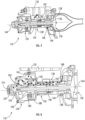
- the power module 110 is shown.
- the power module 110 is in fluid communication with the fuel module 112 (shown in FIG. 1 ) to receive a flow of liquid fuel 128 (shown in FIG. 4 ) and includes a gas generator 132, a compressor 134, and a turbine 136.
- the power module 110 also includes a permanent magnet generator 138, an interconnect shaft 140 (shown in FIG. 5 ), a first air bearing 142 (shown in FIG. 5 ), and a second air bearing 144 (shown in FIG. 5 ).
- the compressor 134 is configured to compress ambient air 129 ingested from the external environment and is operatively associated with the turbine 136.
- a first compressed air portion 146 is provided to the gas generator 132 as an oxidizer for a flow of liquid fuel 128 provided thereto by the turbine speed control valve 126 (shown in FIG. 2 ).
- a second compressed air portion 148 is provided to the first air bearing 142 (shown in FIG. 5 ) and the second air bearing 144 (shown in FIG. 5 ) for supporting the turbine 136 and the compressor for rotation about a rotation axis 164.
- the second compressed air portion 148 is also provided to the permanent magnet generator 138 for purposes of cooling the permanent magnet generator 138.
- the gas generator 132 is configured and adapted to generate a flow of high pressure combustion products 150 and is in fluid communication with fuel module 112, the compressor 134, and the turbine 136.
- the gas generator 132 includes a combustor 152 and a glow-plug or igniter element 154.
- the glow-plug or igniter element 154 is fixed to the combustor 152.
- the combustor 152 is disposed in fluid communication with the turbine speed control valve 126 to receive a flow of the liquid fuel 128, is also disposed in fluid communication with the compressor to receive the second compressed air portion 148 from the compressor 134, and is additionally in fluid communication with the turbine 136 to communicate the flow of high pressure combustion products 150 thereto.
- the turbine 136 is in fluid communication with the gas generator 132 to receive the flow of high pressure combustion products 150 (shown in FIG. 4 ) therefrom, and is operably connected to the permanent magnet generator 138 and the compressor 134 by the interconnect shaft 140.
- the turbine 136 is configured to expand the flow of high pressure combustion products 150 received from the gas generator 132, extract mechanical work therefrom, and communicate the mechanical work to the permanent magnet generator 138 and the compressor 134 to generate electric power and compress air ingested from the from the ambient environment, respectively.
- the turbine 136 is a micro turbine, e.g., is on the order of about four (4) inches (10.2 centimeters) in diameter.
- the turbine 136 includes an impulse turbine 156 operably connected to the compressor 134 and the permanent magnet generator 138, providing radial compactness to the turbine 136. It is also contemplated that, in accordance with certain embodiments, the turbine 136 include a single turbine stage 158 to provide axial compactness to the turbine 136.
- the permanent magnet generator 138 is configured and adapted for generating a flow of variable frequency alternating current (AC) power and is arranged axially between the turbine 136 and the compressor 134.
- the permanent magnet generator 138 includes one or more permanent magnet 160 and a coil or winding 162.
- the permanent magnet 160 is fixed in rotation relative to the interconnect shaft 140 for rotation therewith about a rotation axis 164.
- the stator coil or winding 162 is fixed relative to the gas generator 132, is magnetically coupled the permanent magnet 160, and is electrically connected to a power converter 186 (shown in FIG. 3 ), which is in turn configured to convert the variable frequency AC power into constant frequency power, e.g., direct current (DC) power, for provision to the electric motors 104.
- DC direct current
- the permanent magnet generator 138 is an alternator-type generator, providing the generator arrangement 108 with power density suitable for medium-sized unmanned aerial vehicles.
- the permanent magnet generator 138 can be used as a starter motor for the power module 110.
- the first air bearing 142 and the second air bearing 144 are arranged along the rotation axis 164 on axially opposite ends of the permanent magnet generator 138. More specifically, the first air bearing 142 is arranged axially between the compressor 134 and the permanent magnet generator 138 and the second air bearing 144 is arranged axially between the permanent magnet generator 138 and the turbine 136. This provides a balanced and axially compact arrangement to the power module 110.
- the first air bearing 142 includes a foil-air bearing 170.
- the second air bearing 144 includes a foil-air bearing 172.
- Foil-air bearings allow the power module 110 to operate at high rotational speeds and without a lubricant by floating the rotary member, e.g., the interconnect shaft 140 and/or the compressor 134 and the turbine 136, using the first compressed air portion 146.
- first air bearing 142 and the second air bearing 144 each be in fluid communication with the compressor 134 for supporting the interconnect shaft 140, and therethrough the compressor 134 and the turbine 136, for rotation about the rotation axis 164.
- the compressor 134 is in fluid communication with the first air bearing 142.
- the first air bearing 142 is in turn in fluid communication with the permanent magnet generator 138.
- the permanent magnet generator 138 is in fluid communication with the second air bearing 144, and the second air bearing 144 is in turn in fluid communication with the ambient environment through an outlet port 168.
- the first air bearing 142 receives a flow of compressed air, e.g., a first compressed air portion 146, from the compressor 134.
- the first compressed air portion 146 is relatively low pressure and is communicated from the radially inner first stage of the compressor 134, which also forms the inlet of the radially outer second stage of the compressor 134, to the first air bearing 142.
- the first air bearing 142 in turn communicates the first compressed air portion 146 to the permanent magnet generator 138, wherein the first compressed air portion 146 cools the stator coil or winding 162 of the permanent magnet generator 138 prior to communication therefrom to the second air bearing 144.
- the second air bearing 144 thereafter communicates the first compressed air portion 146 to the ambient environment through a outlet port 168, which is arranged axially between the second air bearing 144 and the turbine 136 and is fluidly coupled to the external environment.
- a heated coolant i.e. the first compressed air portion 146
- the outlet port 168 thermally separates the turbine 136 from the permanent magnet generator 138, allowing the turbine 136 to be arranged close to the permanent magnet generator 138 notwithstanding its high operating temperature without limiting the reliability of the permanent magnet generator 138.
- the compressor 134 is arranged along the rotation axis 164 opposite the turbine 136, is spaced apart therefrom by the permanent magnet generator 138 and the interconnect shaft 140, and is configured to provide compress the ambient air 129 ingested from the external environment to the generate the first compressed air portion 146 and the second compressed air portion 148.
- the compressor 134 includes an inlet 174, a radial compressor 176, and a diffuser 178.
- the compressor 134 also includes a a regenerative compressor wheel 182.
- the inlet 174 is arranged along the rotation axis 164 on an end of the power module 110 opposite the turbine 136.
- the radial compressor 176 is arranged axially between the inlet 174 and the diffuser 178 and is configured to pressurize the ambient air 129 ingested from the ambient environment to a first pressure.
- the diffuser 178 is arranged axially between the radial compressor 176 and the regenerative compressor wheel 182 and is configured to guide the air pressurized to the first pressure to a collection channel 184 of the regenerative compressor wheel 182.
- the regenerative compressor wheel 182 is in turn arranged between the diffuser 178 and the first air bearing 142, and is configured to divide the air pressurized to the first pressure received from the diffuser 178 into the first compressed air portion 146 and the second compressed air portion 148.
- the first compressed air portion 146 is communicated to the outlet port 168 through the first air bearing 142, the permanent magnet generator 138, and the second air bearing 144.
- the second compressed air portion 148 is further compressed by the regenerative compressor wheel 182 and communicated to the gas generator 132 to a second pressure suitable for oxidizing the liquid fuel 114 received thereby in the gas generator 132. It is contemplated that the second pressure be such that turbine 136 operate as a supersonic partial admission turbine or a supersonic full admission turbine.
- the pressure ratio provided by the compressor 134, and more specifically the regenerative compressor wheel 182 radially outer second stage, is about 50:1, which allows the power module 110 to operate without requiring an on-board oxidizer, e.g., using the ambient air 129.
- the method 200 includes receiving ambient air at a power module having a turbine arranged along a rotation axis, an interconnect shaft fixed in rotation relative to the turbine, and a compressor having a regenerative compressor wheel fixed to the interconnect shaft, e.g., the ambient air 129 (shown in FIG. 4 ) at the power module 110 (shown in FIG. 1 ), as shown with box 210.
- the ambient air is compressed by the radial compressor and divided into a first compressed air portion and a second air portion, e.g., the first compressed air portion 146 (shown in FIG. 4 ) and the second compressed air portion 148 (shown in FIG. 4 ), by the regenerative compressor wheel.
- the compressor and the turbine are supported with the first compressed air portion from the radial compressor.
- the first compressed air portion is communicated to a first air bearing, e.g., the first air bearing 142 (shown in FIG. 5 ), as shown with box 222.
- the compressed air portion thereafter communicated to a second air bearing, e.g., the second air bearing 144 (shown in FIG. 5 ), as shown with box 224.
- the first air portion be communicated to a permanent magnet generator, e.g., the permanent magnet generator 138 (shown in FIG. 3 ), as shown with box 230, the first compressed air portion cooling the permanent magnet generator as the first compressed air portion traverses the permanent magnet generator.
- the second compressed air portion from the compressor is further compressed by the regenerative compressor wheel. Once further compressed the second compressed air portion is communicated to the turbine. Specifically, the second compressed air portion is communicated to a gas generator, e.g., the gas generator 132, where it oxidizes liquid fuel to generate a flow of high pressure combustion produces, which the gas generator provides to the turbine. The turbine in turn expands the high pressure combustion products, extracts work therefrom, and applies the work to the permanent magnet generator and the compressor as mechanical rotation.
- a gas generator e.g., the gas generator 132
- Medium-sized unmanned aerial vehicles such as those with power levels between about one (1) kilowatt and about thirty (30) kilowatts, can have relatively short mission times. This is because the energy density of batteries is generally too low to work as these power levels and internal combustion engines and jet engines is generally too low at these energy levels. While unmanned aerial vehicles having power levels within this range can be powered by remote power supplies by tethering, the operational constraints imposed by a tether in terms of limited range and height generally limit the utility of the unmanned aerial vehicle.
- a regenerative compressor wheel is used to generate a very high compressor ratio within a single compressor stage to generate electrical power a turbine.
- a lightweight, high efficiency Brayton cycle-based, micro turbine is used to operate an alternator.
- the turbine utilizes a kerosene-based fuel, such as JP-8, a primary fuel and atmospheric air as the fuel oxidizer.
- a micro turbo alternator achieved high efficiency by operating a supersonic partial admission turbine at a very high pressure ratio, e.g., with a pressure ratio of about 50:1.
- a high pressure ratio Brayton cycle-based micro turbo alternator provides relatively long operating time to a generator arrangement for a fixed volume of fuel and compressed air. In certain embodiments this is accomplished by using atmospheric air as the primary oxidant for a kerosene-based fuel, such as JP-8. Use of atmospheric air as the oxidant eliminates the need to carry an oxidant in a dedicated storage vessel.
Landscapes
- Engineering & Computer Science (AREA)
- Mechanical Engineering (AREA)
- General Engineering & Computer Science (AREA)
- Chemical & Material Sciences (AREA)
- Combustion & Propulsion (AREA)
- Aviation & Aerospace Engineering (AREA)
- Structures Of Non-Positive Displacement Pumps (AREA)
Claims (9)
- Agencement de générateur (108), comprenant :un module de puissance (110), comprenant :une turbine (136) agencée le long d'un axe de rotation ;un arbre d'interconnexion (140) fixe en rotation par rapport à la turbine (136) ; etun compresseur (134) avec une roue de compresseur régénératif (182) fixe en rotation par rapport à l'arbre d'interconnexion (140) supporté pour rotation avec la turbine (136) autour de l'axe de rotation ; dans lequel la turbine est une turbine à impulsion (156) ;un palier à air (142) agencé axialement entre la turbine (136) et la roue de compresseur régénératif (182), le palier à air (142) supportant la turbine (136) et la roue de compresseur régénératif (182) pour une rotation autour de l'axe de rotation ; etun générateur de gaz (132) couplant fluidiquement la roue de compresseur régénératif (182) à la turbine (136) ;caractérisé en ce qu'il comprend en outre :un compresseur radial (176) en communication fluidique avec la roue de compresseur régénératif (182), le compresseur radial (176) étant agencé sur un côté de la roue de compresseur régénératif (182) axialement opposé à la turbine (136) ;un module de carburant de purge (112) en communication fluidique avec le générateur de gaz ; etun orifice de sortie (168) en communication fluidique avec la roue de compresseur régénératif (182),dans lequel l'orifice de sortie (168) est défini axialement entre la roue de compresseur régénératif (182) et la turbine (136) .
- Agencement de générateur (108) selon la revendication 1, comprenant en outre un générateur à aimants permanents (138) relié de manière fonctionnelle à la turbine (136) et agencé axialement entre la turbine (136) et la roue de compresseur régénératif (182).
- Agencement de générateur (108) selon la revendication 2, comprenant en outre un ou plusieurs aimants permanents fixés par rapport à l'arbre d'interconnexion (140), ou comprenant en outre une bobine ou un enroulement de stator agencé radialement à l'extérieur de l'arbre d'interconnexion (140) et en communication fluidique avec la roue de compresseur régénératif (182) pour en recevoir le réfrigérant.
- Agencement de générateur (108) selon une quelconque revendication précédente, dans lequel le palier à air (142) est en communication fluidique avec la roue de compresseur régénératif (182) pour recevoir un flux d'air comprimé provenant de la roue de compresseur régénératif (182), ou dans lequel le palier à air (142) est un premier palier à air (142) et comprenant en outre :un second palier à air (144) supportant la turbine (136) et la roue de compresseur régénératif (182) pour une rotation autour de l'axe de rotation ; etun générateur à aimants permanents (138) agencé axialement entre le premier palier à air (142) et le second palier à air (144), dans lequel le second palier à air (144) est en communication fluidique avec la roue de compresseur régénératif (182) à travers à la fois le premier palier à air (142) et le générateur à aimants permanents (138).
- Agencement de générateur selon une quelconque revendication précédente,
dans lequel le module de carburant de purge (112) comprend :une charge de carburant liquide contenue à l'intérieur d'un réservoir de carburant sous pression (120) ; etune charge de gaz comprimé en communication fluidique avec la turbine à travers le réservoir de carburant sous pression (120), la charge de gaz comprimé pressurisant la charge de carburant liquide. - Agencement de générateur selon une quelconque revendication précédente, dans lequel la turbine (136) comporte un seul étage de turbine.
- Véhicule aérien sans pilote (100), comprenant :une cellule (102) supportant une charge électrique (103) ;un agencement de générateur (108) selon l'une quelconque des revendications 1 à 6, dans lequel le module de puissance (110) est porté par le véhicule aérien sans pilote (100) et est électriquement relié à la charge électrique (103) ; etle module de carburant de purge (112) est en communication fluidique avec le module de puissance.
- Procédé de génération d'énergie électrique, comprenant :la réception d'air ambiant au niveau d'un agencement de générateur (108) ; qui comporte :
un module de puissance (110) ayant une turbine (136) agencée le long d'un axe de rotation, un arbre d'interconnexion (140) fixe en rotation par rapport à la turbine (136), et un compresseur (134) ayant une roue de compresseur régénératif (182) fixe à l'arbre d'interconnexion (140) ; dans lequel la turbine est une turbine à impulsion (156) ;le module de puissance (110) comprenant en outre :un palier à air (142) agencé axialement entre la turbine (136) et la roue de compresseur régénératif (182), le palier à air (142) supportant la turbine (136) et la roue de compresseur régénératif (182) pour une rotation autour de l'axe de rotation ;un compresseur radial (176) en communication fluidique avec la roue de compresseur régénératif (182), le compresseur radial (176) étant agencé sur un côté de la roue de compresseur régénératif (182) axialement opposé à la turbine (136) ;un générateur de gaz (132) couplant fluidiquement la roue de compresseur régénératif (182) à la turbine (136) ;un module de carburant de purge (112) en communication fluidique avec le générateur de gaz ; etun orifice de sortie (168) en communication fluidique avec la roue de compresseur régénératif (182),dans lequel l'orifice de sortie (168) est défini axialement entre la roue de compresseur régénératif (182) et la turbine (136) ;le procédé comprenant en outre :le support du compresseur (134) et de la turbine (136) avec une première partie d'air comprimé provenant du compresseur (134) ;la compression d'une seconde partie d'air comprimé avec le compresseur (134) ; etla communication de la seconde partie d'air comprimé à la turbine (136) pour générer de l'énergie électrique avec le module de puissance (110). - Procédé selon la revendication 8, comprenant en outre le refroidissement d'un générateur à aimants permanents agencé axialement entre le compresseur (134) et la turbine (136) avec la première partie d'air comprimé provenant du compresseur (134) .
Applications Claiming Priority (1)
| Application Number | Priority Date | Filing Date | Title |
|---|---|---|---|
| US16/383,628 US11359635B2 (en) | 2019-04-14 | 2019-04-14 | Power modules with regenerative compressor wheels |
Publications (2)
| Publication Number | Publication Date |
|---|---|
| EP3726025A1 EP3726025A1 (fr) | 2020-10-21 |
| EP3726025B1 true EP3726025B1 (fr) | 2023-03-22 |
Family
ID=68917417
Family Applications (1)
| Application Number | Title | Priority Date | Filing Date |
|---|---|---|---|
| EP19216265.9A Active EP3726025B1 (fr) | 2019-04-14 | 2019-12-13 | Modules de puissance dotés de roues de compresseur régénératif |
Country Status (2)
| Country | Link |
|---|---|
| US (2) | US11359635B2 (fr) |
| EP (1) | EP3726025B1 (fr) |
Families Citing this family (5)
| Publication number | Priority date | Publication date | Assignee | Title |
|---|---|---|---|---|
| US11359635B2 (en) | 2019-04-14 | 2022-06-14 | Hamilton Sundstrand Corporation | Power modules with regenerative compressor wheels |
| US11530705B2 (en) * | 2020-11-17 | 2022-12-20 | Hamilton Sundstrand Corporation | Bearing cooling schemes for aircraft fans |
| US20230089729A1 (en) * | 2021-09-10 | 2023-03-23 | Hamilton Sundstrand Corporation | Stress relieving compressor shroud compression rings |
| US12060799B2 (en) | 2022-04-01 | 2024-08-13 | Hamilton Sundstrand Corporation | Turbine thermal isolation system for micro-turbine alternator |
| US12055156B2 (en) * | 2022-04-01 | 2024-08-06 | Hamilton Sundstrand Corporation | High speed turbo-alternator with integrated cooling fan |
Citations (1)
| Publication number | Priority date | Publication date | Assignee | Title |
|---|---|---|---|---|
| US5899673A (en) * | 1996-10-16 | 1999-05-04 | Capstone Turbine Corporation | Helical flow compressor/turbine permanent magnet motor/generator |
Family Cites Families (27)
| Publication number | Priority date | Publication date | Assignee | Title |
|---|---|---|---|---|
| EP0567874B1 (fr) * | 1992-04-27 | 1995-09-06 | Gebrüder Becker GmbH & Co. | Machine à courant pour la compression d'un gaz |
| US5497615A (en) * | 1994-03-21 | 1996-03-12 | Noe; James C. | Gas turbine generator set |
| US5932940A (en) | 1996-07-16 | 1999-08-03 | Massachusetts Institute Of Technology | Microturbomachinery |
| TW390936B (en) | 1997-12-20 | 2000-05-21 | Allied Signal Inc | Microturbine power generating system |
| JPH11311243A (ja) | 1998-03-27 | 1999-11-09 | Aisin Seiki Co Ltd | エアベアリングおよびエアベアリングを備えたハイブリッドチャ―ジャ |
| GB2366333B (en) | 2000-08-31 | 2005-02-23 | Turbo Genset Company Ltd | Radial regenerative turbomachine |
| US7001162B2 (en) | 2001-02-01 | 2006-02-21 | Ewan Choroszylow | Compressor assembly |
| US6920895B2 (en) | 2001-04-16 | 2005-07-26 | Alan Avis | Combination surge supression and safety shut-off valve |
| US6574950B2 (en) | 2001-10-01 | 2003-06-10 | Ingersoll-Rand Energy Systems Corporation | Thermally responsive recuperator housing |
| US7313916B2 (en) | 2002-03-22 | 2008-01-01 | Philip Morris Usa Inc. | Method and apparatus for generating power by combustion of vaporized fuel |
| US7047722B2 (en) | 2002-10-02 | 2006-05-23 | Claudio Filippone | Small scale hybrid engine (SSHE) utilizing fossil fuels |
| GB2410982A (en) * | 2004-02-14 | 2005-08-17 | Richard Julius Gozdawa | Turbomachinery electric generator arrangement with component cooling |
| US7013636B2 (en) | 2004-04-22 | 2006-03-21 | The Boeing Company | System and method for controlling the temperature and infrared signature of an engine |
| US7575192B1 (en) | 2005-12-16 | 2009-08-18 | Locust Usa, Inc. | Transmission system for use in microturbine-powered applications |
| BRPI0821737A8 (pt) | 2007-12-21 | 2018-12-18 | Green Prtners Tech Holdings Gmbh | sistemas de turbina a gás de ciclo aberto e fechado e semi-fechado para geração de energia e de turbina de expansão e compressor de pistão fechado, turbocompressor e métodos de produção de energia com turbina de gás de ciclo aberto, de compressão de gás de operação em turbocompressor e de operação de sistema de motor |
| US8191571B2 (en) | 2008-07-30 | 2012-06-05 | Hamilton Sundstrand Corporation | Fluid circuit breaker quick disconnect coupling |
| US8636247B2 (en) | 2011-04-19 | 2014-01-28 | Raytheon Company | Closed gas generator and micro power unit including the same |
| FR2978728B1 (fr) | 2011-08-03 | 2014-07-04 | Eads Europ Aeronautic Defence | Architecture de propulsion d'aeronef integrant un systeme de recuperation d'energie |
| CA2853360A1 (fr) * | 2011-10-24 | 2013-05-02 | Hybrid Turbine Group | Turbine a reaction et turbine hybride a reaction et impulsion |
| US9024460B2 (en) | 2012-01-04 | 2015-05-05 | General Electric Company | Waste heat recovery system generator encapsulation |
| DE102012204403A1 (de) * | 2012-03-20 | 2013-09-26 | Man Diesel & Turbo Se | Radialverdichtereinheit |
| US9376214B2 (en) | 2014-09-28 | 2016-06-28 | Reebeez, Inc. | Hybrid propulsion power system for aerial vehicles |
| US20160176534A1 (en) | 2014-12-19 | 2016-06-23 | Hamilton Sundstrand Corporation | Emergency power sources for propulsion systems |
| GB201509458D0 (en) * | 2015-06-01 | 2015-07-15 | Samad Power Ltd | Micro-CHP gas fired boiler with gas turbine assembly |
| US20180023472A1 (en) | 2016-07-22 | 2018-01-25 | Brent Wei-Teh LEE | Engine, rotary device, power generator, power generation system, and methods of making and using the same |
| US10641123B1 (en) * | 2018-03-22 | 2020-05-05 | Florida Turbine Technologies, Inc. | Generator cooling impeller and bearing/rotor cooling |
| US11359635B2 (en) | 2019-04-14 | 2022-06-14 | Hamilton Sundstrand Corporation | Power modules with regenerative compressor wheels |
-
2019
- 2019-04-14 US US16/383,628 patent/US11359635B2/en active Active
- 2019-12-13 EP EP19216265.9A patent/EP3726025B1/fr active Active
-
2022
- 2022-06-13 US US17/838,732 patent/US11732723B2/en active Active
Patent Citations (1)
| Publication number | Priority date | Publication date | Assignee | Title |
|---|---|---|---|---|
| US5899673A (en) * | 1996-10-16 | 1999-05-04 | Capstone Turbine Corporation | Helical flow compressor/turbine permanent magnet motor/generator |
Also Published As
| Publication number | Publication date |
|---|---|
| US20200325904A1 (en) | 2020-10-15 |
| US20220316486A1 (en) | 2022-10-06 |
| US20240133388A1 (en) | 2024-04-25 |
| EP3726025A1 (fr) | 2020-10-21 |
| US20240229807A9 (en) | 2024-07-11 |
| US11732723B2 (en) | 2023-08-22 |
| US11359635B2 (en) | 2022-06-14 |
Similar Documents
| Publication | Publication Date | Title |
|---|---|---|
| EP3726022B1 (fr) | Modules de récupération d'énergie, agencements de générateur et procédés de récupération d'énergie dans des agencements de générateur | |
| EP3726025B1 (fr) | Modules de puissance dotés de roues de compresseur régénératif | |
| US20200355117A1 (en) | Multi-stage turbocharging compressor for fuel cell systems | |
| US5831341A (en) | Turboalternator for hybrid motor vehicle | |
| US20150285165A1 (en) | Unmanned Aircraft and Operation Method for the Same | |
| US5893423A (en) | Integration of turboalternator for hybrid motor vehicle | |
| CN109139268A (zh) | 用于起动涡轮发动机的系统和方法 | |
| EP3726024B1 (fr) | Séparateur de saletés cyclonique pour micro-turboalternateur basé sur cycle de brayton haute efficacité | |
| EP4159990A2 (fr) | Système combiné intégré de récupération de chaleur perdue et d'amplification de pression d'entrée | |
| US20240002066A1 (en) | Simultaneous air cooling of multiple elements of a hybrid powerplant | |
| US12104606B2 (en) | Power modules with regenerative compressor wheels | |
| US5789824A (en) | Cooling of turboalternator for hybrid motor vehicle | |
| EP4148281A1 (fr) | Anneaux de compression de virole de compresseur à relaxation de contrainte | |
| EP3736427B1 (fr) | Modules de puissance pour véhicules hypersoniques | |
| US11920510B2 (en) | Interstage electric alternator for micro-turbine alternator applications | |
| US5796173A (en) | Hydraulic fit of turboalternator for hybrid motor vehicle | |
| EP4148243A1 (fr) | Turbine multi-étages de générateur de micro-turbine dotée d'un convertisseur catalytique inter-étages | |
| US11459945B1 (en) | Micro-turbine generator multi-stage turbine with integrated reheat cycle | |
| EP4148232B1 (fr) | Palier de butée à isolation thermique, préchargé magnétiquement et couplé, et ensemble support radial et arbre | |
| EP3726011A1 (fr) | Module de puissance doté d'un système d'alimentation de propergol et de carburant par purge | |
| WO2023249660A1 (fr) | Dérivation de compresseur pour opérations à basse altitude |
Legal Events
| Date | Code | Title | Description |
|---|---|---|---|
| PUAI | Public reference made under article 153(3) epc to a published international application that has entered the european phase |
Free format text: ORIGINAL CODE: 0009012 |
|
| STAA | Information on the status of an ep patent application or granted ep patent |
Free format text: STATUS: THE APPLICATION HAS BEEN PUBLISHED |
|
| AK | Designated contracting states |
Kind code of ref document: A1 Designated state(s): AL AT BE BG CH CY CZ DE DK EE ES FI FR GB GR HR HU IE IS IT LI LT LU LV MC MK MT NL NO PL PT RO RS SE SI SK SM TR |
|
| STAA | Information on the status of an ep patent application or granted ep patent |
Free format text: STATUS: REQUEST FOR EXAMINATION WAS MADE |
|
| 17P | Request for examination filed |
Effective date: 20210421 |
|
| RBV | Designated contracting states (corrected) |
Designated state(s): AL AT BE BG CH CY CZ DE DK EE ES FI FR GB GR HR HU IE IS IT LI LT LU LV MC MK MT NL NO PL PT RO RS SE SI SK SM TR |
|
| GRAP | Despatch of communication of intention to grant a patent |
Free format text: ORIGINAL CODE: EPIDOSNIGR1 |
|
| STAA | Information on the status of an ep patent application or granted ep patent |
Free format text: STATUS: GRANT OF PATENT IS INTENDED |
|
| INTG | Intention to grant announced |
Effective date: 20220928 |
|
| GRAS | Grant fee paid |
Free format text: ORIGINAL CODE: EPIDOSNIGR3 |
|
| GRAA | (expected) grant |
Free format text: ORIGINAL CODE: 0009210 |
|
| STAA | Information on the status of an ep patent application or granted ep patent |
Free format text: STATUS: THE PATENT HAS BEEN GRANTED |
|
| AK | Designated contracting states |
Kind code of ref document: B1 Designated state(s): AL AT BE BG CH CY CZ DE DK EE ES FI FR GB GR HR HU IE IS IT LI LT LU LV MC MK MT NL NO PL PT RO RS SE SI SK SM TR |
|
| REG | Reference to a national code |
Ref country code: GB Ref legal event code: FG4D |
|
| REG | Reference to a national code |
Ref country code: CH Ref legal event code: EP |
|
| REG | Reference to a national code |
Ref country code: IE Ref legal event code: FG4D |
|
| REG | Reference to a national code |
Ref country code: DE Ref legal event code: R096 Ref document number: 602019026620 Country of ref document: DE |
|
| REG | Reference to a national code |
Ref country code: AT Ref legal event code: REF Ref document number: 1555419 Country of ref document: AT Kind code of ref document: T Effective date: 20230415 |
|
| REG | Reference to a national code |
Ref country code: LT Ref legal event code: MG9D |
|
| P01 | Opt-out of the competence of the unified patent court (upc) registered |
Effective date: 20230603 |
|
| REG | Reference to a national code |
Ref country code: NL Ref legal event code: MP Effective date: 20230322 |
|
| PG25 | Lapsed in a contracting state [announced via postgrant information from national office to epo] |
Ref country code: RS Free format text: LAPSE BECAUSE OF FAILURE TO SUBMIT A TRANSLATION OF THE DESCRIPTION OR TO PAY THE FEE WITHIN THE PRESCRIBED TIME-LIMIT Effective date: 20230322 Ref country code: NO Free format text: LAPSE BECAUSE OF FAILURE TO SUBMIT A TRANSLATION OF THE DESCRIPTION OR TO PAY THE FEE WITHIN THE PRESCRIBED TIME-LIMIT Effective date: 20230622 Ref country code: LV Free format text: LAPSE BECAUSE OF FAILURE TO SUBMIT A TRANSLATION OF THE DESCRIPTION OR TO PAY THE FEE WITHIN THE PRESCRIBED TIME-LIMIT Effective date: 20230322 Ref country code: LT Free format text: LAPSE BECAUSE OF FAILURE TO SUBMIT A TRANSLATION OF THE DESCRIPTION OR TO PAY THE FEE WITHIN THE PRESCRIBED TIME-LIMIT Effective date: 20230322 Ref country code: HR Free format text: LAPSE BECAUSE OF FAILURE TO SUBMIT A TRANSLATION OF THE DESCRIPTION OR TO PAY THE FEE WITHIN THE PRESCRIBED TIME-LIMIT Effective date: 20230322 |
|
| REG | Reference to a national code |
Ref country code: AT Ref legal event code: MK05 Ref document number: 1555419 Country of ref document: AT Kind code of ref document: T Effective date: 20230322 |
|
| PG25 | Lapsed in a contracting state [announced via postgrant information from national office to epo] |
Ref country code: SE Free format text: LAPSE BECAUSE OF FAILURE TO SUBMIT A TRANSLATION OF THE DESCRIPTION OR TO PAY THE FEE WITHIN THE PRESCRIBED TIME-LIMIT Effective date: 20230322 Ref country code: NL Free format text: LAPSE BECAUSE OF FAILURE TO SUBMIT A TRANSLATION OF THE DESCRIPTION OR TO PAY THE FEE WITHIN THE PRESCRIBED TIME-LIMIT Effective date: 20230322 Ref country code: GR Free format text: LAPSE BECAUSE OF FAILURE TO SUBMIT A TRANSLATION OF THE DESCRIPTION OR TO PAY THE FEE WITHIN THE PRESCRIBED TIME-LIMIT Effective date: 20230623 Ref country code: FI Free format text: LAPSE BECAUSE OF FAILURE TO SUBMIT A TRANSLATION OF THE DESCRIPTION OR TO PAY THE FEE WITHIN THE PRESCRIBED TIME-LIMIT Effective date: 20230322 |
|
| PG25 | Lapsed in a contracting state [announced via postgrant information from national office to epo] |
Ref country code: SM Free format text: LAPSE BECAUSE OF FAILURE TO SUBMIT A TRANSLATION OF THE DESCRIPTION OR TO PAY THE FEE WITHIN THE PRESCRIBED TIME-LIMIT Effective date: 20230322 Ref country code: RO Free format text: LAPSE BECAUSE OF FAILURE TO SUBMIT A TRANSLATION OF THE DESCRIPTION OR TO PAY THE FEE WITHIN THE PRESCRIBED TIME-LIMIT Effective date: 20230322 Ref country code: PT Free format text: LAPSE BECAUSE OF FAILURE TO SUBMIT A TRANSLATION OF THE DESCRIPTION OR TO PAY THE FEE WITHIN THE PRESCRIBED TIME-LIMIT Effective date: 20230724 Ref country code: ES Free format text: LAPSE BECAUSE OF FAILURE TO SUBMIT A TRANSLATION OF THE DESCRIPTION OR TO PAY THE FEE WITHIN THE PRESCRIBED TIME-LIMIT Effective date: 20230322 Ref country code: EE Free format text: LAPSE BECAUSE OF FAILURE TO SUBMIT A TRANSLATION OF THE DESCRIPTION OR TO PAY THE FEE WITHIN THE PRESCRIBED TIME-LIMIT Effective date: 20230322 Ref country code: AT Free format text: LAPSE BECAUSE OF FAILURE TO SUBMIT A TRANSLATION OF THE DESCRIPTION OR TO PAY THE FEE WITHIN THE PRESCRIBED TIME-LIMIT Effective date: 20230322 |
|
| PG25 | Lapsed in a contracting state [announced via postgrant information from national office to epo] |
Ref country code: SK Free format text: LAPSE BECAUSE OF FAILURE TO SUBMIT A TRANSLATION OF THE DESCRIPTION OR TO PAY THE FEE WITHIN THE PRESCRIBED TIME-LIMIT Effective date: 20230322 Ref country code: PL Free format text: LAPSE BECAUSE OF FAILURE TO SUBMIT A TRANSLATION OF THE DESCRIPTION OR TO PAY THE FEE WITHIN THE PRESCRIBED TIME-LIMIT Effective date: 20230322 Ref country code: IS Free format text: LAPSE BECAUSE OF FAILURE TO SUBMIT A TRANSLATION OF THE DESCRIPTION OR TO PAY THE FEE WITHIN THE PRESCRIBED TIME-LIMIT Effective date: 20230722 |
|
| REG | Reference to a national code |
Ref country code: DE Ref legal event code: R097 Ref document number: 602019026620 Country of ref document: DE |
|
| PGFP | Annual fee paid to national office [announced via postgrant information from national office to epo] |
Ref country code: GB Payment date: 20231121 Year of fee payment: 5 |
|
| PLBE | No opposition filed within time limit |
Free format text: ORIGINAL CODE: 0009261 |
|
| STAA | Information on the status of an ep patent application or granted ep patent |
Free format text: STATUS: NO OPPOSITION FILED WITHIN TIME LIMIT |
|
| PG25 | Lapsed in a contracting state [announced via postgrant information from national office to epo] |
Ref country code: SI Free format text: LAPSE BECAUSE OF FAILURE TO SUBMIT A TRANSLATION OF THE DESCRIPTION OR TO PAY THE FEE WITHIN THE PRESCRIBED TIME-LIMIT Effective date: 20230322 Ref country code: DK Free format text: LAPSE BECAUSE OF FAILURE TO SUBMIT A TRANSLATION OF THE DESCRIPTION OR TO PAY THE FEE WITHIN THE PRESCRIBED TIME-LIMIT Effective date: 20230322 Ref country code: CZ Free format text: LAPSE BECAUSE OF FAILURE TO SUBMIT A TRANSLATION OF THE DESCRIPTION OR TO PAY THE FEE WITHIN THE PRESCRIBED TIME-LIMIT Effective date: 20230322 |
|
| PGFP | Annual fee paid to national office [announced via postgrant information from national office to epo] |
Ref country code: FR Payment date: 20231122 Year of fee payment: 5 Ref country code: DE Payment date: 20231121 Year of fee payment: 5 |
|
| 26N | No opposition filed |
Effective date: 20240102 |
|
| PG25 | Lapsed in a contracting state [announced via postgrant information from national office to epo] |
Ref country code: IT Free format text: LAPSE BECAUSE OF FAILURE TO SUBMIT A TRANSLATION OF THE DESCRIPTION OR TO PAY THE FEE WITHIN THE PRESCRIBED TIME-LIMIT Effective date: 20230322 |
|
| REG | Reference to a national code |
Ref country code: CH Ref legal event code: PL |
|
| PG25 | Lapsed in a contracting state [announced via postgrant information from national office to epo] |
Ref country code: LU Free format text: LAPSE BECAUSE OF NON-PAYMENT OF DUE FEES Effective date: 20231213 |
|
| PG25 | Lapsed in a contracting state [announced via postgrant information from national office to epo] |
Ref country code: MC Free format text: LAPSE BECAUSE OF FAILURE TO SUBMIT A TRANSLATION OF THE DESCRIPTION OR TO PAY THE FEE WITHIN THE PRESCRIBED TIME-LIMIT Effective date: 20230322 |
|
| REG | Reference to a national code |
Ref country code: BE Ref legal event code: MM Effective date: 20231231 |
|
| PG25 | Lapsed in a contracting state [announced via postgrant information from national office to epo] |
Ref country code: MC Free format text: LAPSE BECAUSE OF FAILURE TO SUBMIT A TRANSLATION OF THE DESCRIPTION OR TO PAY THE FEE WITHIN THE PRESCRIBED TIME-LIMIT Effective date: 20230322 Ref country code: LU Free format text: LAPSE BECAUSE OF NON-PAYMENT OF DUE FEES Effective date: 20231213 |