EP3725993B1 - Brandschutzverglasung - Google Patents
Brandschutzverglasung Download PDFInfo
- Publication number
- EP3725993B1 EP3725993B1 EP19169424.9A EP19169424A EP3725993B1 EP 3725993 B1 EP3725993 B1 EP 3725993B1 EP 19169424 A EP19169424 A EP 19169424A EP 3725993 B1 EP3725993 B1 EP 3725993B1
- Authority
- EP
- European Patent Office
- Prior art keywords
- fire protection
- panes
- fire
- profile elements
- glazing
- Prior art date
- Legal status (The legal status is an assumption and is not a legal conclusion. Google has not performed a legal analysis and makes no representation as to the accuracy of the status listed.)
- Active
Links
Images


Classifications
-
- E—FIXED CONSTRUCTIONS
- E06—DOORS, WINDOWS, SHUTTERS, OR ROLLER BLINDS IN GENERAL; LADDERS
- E06B—FIXED OR MOVABLE CLOSURES FOR OPENINGS IN BUILDINGS, VEHICLES, FENCES OR LIKE ENCLOSURES IN GENERAL, e.g. DOORS, WINDOWS, BLINDS, GATES
- E06B5/00—Doors, windows, or like closures for special purposes; Border constructions therefor
- E06B5/10—Doors, windows, or like closures for special purposes; Border constructions therefor for protection against air-raid or other war-like action; for other protective purposes
- E06B5/16—Fireproof doors or similar closures; Adaptations of fixed constructions therefor
-
- E—FIXED CONSTRUCTIONS
- E04—BUILDING
- E04B—GENERAL BUILDING CONSTRUCTIONS; WALLS, e.g. PARTITIONS; ROOFS; FLOORS; CEILINGS; INSULATION OR OTHER PROTECTION OF BUILDINGS
- E04B2/00—Walls, e.g. partitions, for buildings; Wall construction with regard to insulation; Connections specially adapted to walls
- E04B2/74—Removable non-load-bearing partitions; Partitions with a free upper edge
- E04B2/7407—Removable non-load-bearing partitions; Partitions with a free upper edge assembled using frames with infill panels or coverings only; made-up of panels and a support structure incorporating posts
- E04B2/7453—Removable non-load-bearing partitions; Partitions with a free upper edge assembled using frames with infill panels or coverings only; made-up of panels and a support structure incorporating posts with panels and support posts, extending from floor to ceiling
- E04B2/7455—Glazing details
-
- E—FIXED CONSTRUCTIONS
- E06—DOORS, WINDOWS, SHUTTERS, OR ROLLER BLINDS IN GENERAL; LADDERS
- E06B—FIXED OR MOVABLE CLOSURES FOR OPENINGS IN BUILDINGS, VEHICLES, FENCES OR LIKE ENCLOSURES IN GENERAL, e.g. DOORS, WINDOWS, BLINDS, GATES
- E06B3/00—Window sashes, door leaves, or like elements for closing wall or like openings; Layout of fixed or moving closures, e.g. windows in wall or like openings; Features of rigidly-mounted outer frames relating to the mounting of wing frames
- E06B3/54—Fixing of glass panes or like plates
- E06B3/56—Fixing of glass panes or like plates by means of putty, cement, or adhesives only
-
- E—FIXED CONSTRUCTIONS
- E04—BUILDING
- E04B—GENERAL BUILDING CONSTRUCTIONS; WALLS, e.g. PARTITIONS; ROOFS; FLOORS; CEILINGS; INSULATION OR OTHER PROTECTION OF BUILDINGS
- E04B2/00—Walls, e.g. partitions, for buildings; Wall construction with regard to insulation; Connections specially adapted to walls
- E04B2/74—Removable non-load-bearing partitions; Partitions with a free upper edge
- E04B2/7407—Removable non-load-bearing partitions; Partitions with a free upper edge assembled using frames with infill panels or coverings only; made-up of panels and a support structure incorporating posts
- E04B2/7409—Removable non-load-bearing partitions; Partitions with a free upper edge assembled using frames with infill panels or coverings only; made-up of panels and a support structure incorporating posts special measures for sound or thermal insulation, including fire protection
- E04B2/7411—Details for fire protection
-
- E—FIXED CONSTRUCTIONS
- E06—DOORS, WINDOWS, SHUTTERS, OR ROLLER BLINDS IN GENERAL; LADDERS
- E06B—FIXED OR MOVABLE CLOSURES FOR OPENINGS IN BUILDINGS, VEHICLES, FENCES OR LIKE ENCLOSURES IN GENERAL, e.g. DOORS, WINDOWS, BLINDS, GATES
- E06B3/00—Window sashes, door leaves, or like elements for closing wall or like openings; Layout of fixed or moving closures, e.g. windows in wall or like openings; Features of rigidly-mounted outer frames relating to the mounting of wing frames
- E06B3/54—Fixing of glass panes or like plates
- E06B3/5427—Fixing of glass panes or like plates the panes mounted flush with the surrounding frame or with the surrounding panes
-
- E—FIXED CONSTRUCTIONS
- E06—DOORS, WINDOWS, SHUTTERS, OR ROLLER BLINDS IN GENERAL; LADDERS
- E06B—FIXED OR MOVABLE CLOSURES FOR OPENINGS IN BUILDINGS, VEHICLES, FENCES OR LIKE ENCLOSURES IN GENERAL, e.g. DOORS, WINDOWS, BLINDS, GATES
- E06B3/00—Window sashes, door leaves, or like elements for closing wall or like openings; Layout of fixed or moving closures, e.g. windows in wall or like openings; Features of rigidly-mounted outer frames relating to the mounting of wing frames
- E06B3/66—Units comprising two or more parallel glass or like panes permanently secured together
Definitions
- the present invention relates to a fire protection glazing for preventing the passage of fire and smoke from one room to another room in the event of fire, having at least two, vertically, adjacent and coplanar arranged fire protection panes, which are held at their vertical edges by means of two profile elements, at least one profile element is arranged at each of the vertical edges of the fire protection panes, a joint opening being defined between the adjacent horizontal edges of the fire protection panes.
- the present invention further relates to a method for establishing such a fire protection glazing.
- Fire protection glazings are translucent components that prevent the spread of fire and smoke from one room to another, and also prevents the impermissible transition of heat between rooms, within the scope of a certain fire resistance duration. According to the DIN EN 13501 standard, especially the fire resistance classes El and EW are normalized and explained with regard to the requirements, especially for fire classification of construction products and building elements.
- Fire protection panes used for fire protection glazing are normally constructed in multiple layers of glass panes with a fire protection layer arranged in between. In case of fire, a protective material contained in this fire protection layer is activated, whereby the fire protection pane absorbs heat radiation and forms a highly effective insulation layer. As a result the originally transparent glazing creates a practically opaque fire protection wall.
- the fire protection panes used for fire protection glazing are normally fixed by a support construction, especially in frames, which are matched in size and their fire protection properties to the fire protection panes used.
- the frames normally comprise vertically and/or horizontally arranged profile elements which hold respectively carry the fire protection panes and realize load transfer. Since fire protection panes used for fire protection glazings can have a very high weight (especially depending on the requirements according to DIN EN 13501), secure fastening respectively fixing of fire protection panes to support construction is necessary, and correspondingly effortful and expensive. Moreover, the so far known support constructions used for such fire protection glazings can affect the optical appearance and limit the light transmission of these glazings.
- US4500572A and BE1012820A3 disclose glazings having a plurality of panes being vertically, adjacent and coplanar arranged.
- a fire protection glazing for preventing the passage of fire and smoke from one room to another room in the event of fire, which is improved with regard to the mentioned disadvantages and can especially be manufactured respectively established easily and cost-effectively and furthermore especially allows an easy and cost-effective repair respectively replacement of fire protection panes.
- a fire protection glazing according to claim 1 is provided.
- the joint opening between two fire protection panes is closed by sealant only, all along the adjacent horizontal edges of the fire protection panes.
- the at least two, vertically, adjacent and coplanar arranged fire protection panes are held at and all along their vertical edges by means of at least two profile elements.
- the joint opening between two fire protection panes is closed by a silicon paste only.
- the invention is based on the knowledge made through experiments that adhering of fire protection panes to profile elements by means of glue, advantageously by means of glue only, allows respectively enables an easy and cost-effective establishment of fire protection glazing and furthermore an easily and cost-effectively replacement of fire protection panes of the fire protection glazing, whereby the fire protection glazing advantageously fulfils fire protection requirements, especially the requirements according to DIN EN 13501, preferred the fire resistance classes El or EW.
- fire protection panes are adhered only to profile elements which extend vertically between the floor and the ceiling of the rooms.
- the fire protection glazing only comprises profile elements which extend vertically between the floor and the ceiling of the rooms.
- the glue strip may have a width of more than 10mm, such as more than or equal to 12mm or more than or equal to 15mm or even more than or equal to 20mm. In some embodiments of the present invention the glue strip may have width of less than or equal to 50mm, such as less than or equal to 45mm or even less than or equal to 40mm.
- the glue strip may have a thickness of more than or equal to 0.8mm, such as more than or equal to 1.5mm. In some embodiments of the present invention the glue strip may have a thickness of less than or equal to 4mm, such as less than or equal to 3mm. Too thick glue strips may fail under shear stress causing the fire protection panes to loosen from the profile elements when the joint opening is closed by a sealant only.
- At least one glue strip is present along the length of the interface between the surface of the fire protection pane and the profile element.
- the glue strip being continuous along the length of the interface between the surface of the fire protection pane and the profile element.
- the glue strip may be interrupted along the length of the interface between the surface of the fire protection pane and the profile element. In the latter case, two glue strips may partially overlap along the length of the interface between the surface of the fire protection pane and the profile element.
- the glue advantageously may be a silicon glue.
- the joint between two fire protection panes is provided by a silicon paste only. This may result in an improved optical appearance and the light transmission of such inventive fire protection glazing may be further improved.
- the joint opening, or space or gap, between two fire protection panes may be more than or equal to 1mm, or even more than or equal to 2mm, such as more than or equal to 3mm. In some embodiments of the present invention, the joint opening, or space or gap, between two fire protection panes may be less than or equal to 10mm, e.g. less than or equal to 7mm, such as less than or equal to 6mm, e.g. less than or equal to 5mm.
- the profile element may have a cross section which is substantially rectangular, substantially rectangular hollow, substantially U-shaped, substantially H-shaped or substantially L-shaped.
- the profile element may be made of wood, steel, aluminium or concrete. This allows to design the optical appearance of an inventive fire protection glazing with numerous options.
- each fire protection pane is a compound structure of at least two glass panes arranged in parallel to each other, between which in each case at least one fire protection layer is arranged.
- the fire protection pane may be build according to the so-called water-glass-technology or according to the so-called gel-technology.
- a fire protection pane according to the water-glass technology as a fire protection layer between a multiplicity, at least two glass panes are used materials, which in particular comprises an alkali silicate mass, which acts as a foaming agent in the event of fire and lathers up.
- the fire protection layer arranged between two glass panes, which is activated in the event of fire is formed of gelatinous materials, in particular of organic polymers.
- the at least two glass panes of the fire protection pane may be spaced apart from each other by means of a spacer providing an edge-compound, which spacer preferably is arranged between the at least two glass panes of the fire protection pane and particularly preferred extends along the side edges of the fire protection pane.
- the fire protection pane may have a height in a range of more than or equal to 1 meter, such as more than or equal to 1.5m. In some embodiments of the present invention, the fire protection pane may have a width in a range of more than 2 meter, such as more than or equal to 3 meter, even more than or equal to 4m.
- a further embodiment of the present invention is characterized in that the fire protection pane has a weight in a range of ⁇ 25 kg/m 2 and ⁇ 180 kg/m 2 .
- a method for establishing a fire protection glazing according to the first aspect of the invention.
- the method for establishing a fire protection glazing for preventing the passage of fire and smoke from one room to another room in the event of fire comprises the steps of
- the method may comprise, the steps of
- the methods according to the second aspect of the invention may be used to provide a fire protection glazing according to the first aspect of the invention. All preferred features described in relation to the fire protection glazing according to the first aspect of the invention can be used in methods according to the second aspect of the invention.
- the fire protection glazings according to the invention have the advantage that the load transferring setting blocks are not necessarily to be present, hence a load transfer setting block free fire protection glazing can be provided.
- this defect pane of the fire protection glazing can be removed from the glazing by cutting it out of the glazing.
- the sealant along the edge of the remaining panes in the glazing can be removed and a new pane can easily be installed without the need to dismantle all elements and panes of the fire protection glazing.
- Fig. 1 and Fig. 2 show a schematic embodiment of a fire protection glazing 1 for preventing the passage of fire and smoke from one room to another room in the event of fire.
- two, vertically, adjacent and coplanar arranged fire protection panes 2 are held at each of their vertical edges by means of two profile elements 3.
- Each of the profile elements 3 is arranged at each of the vertical edges of the fire protection panes 2.
- the profile elements 3 extend vertically between the floor F and the ceiling C of the rooms.
- Each of the profile elements 3 has a cross section which is substantially rectangular hollow. Between the adjacent horizontal edges of the fire protection panes 2 a joint opening 7a is defined.
- the profile elements 3 are made of wood, steel, aluminium and/or concrete.
- the fire protection pane 2 is adhered to the profile element 3 - in the present embodiment to at least one of the two substantially rectangular hollow profile elements 3, preferably to both of the substantially rectangular hollow profile elements 3 - by means of glue 6.
- the glue 6 being present all the length of the interface 4 between the surface 5 of the fire protection pane 2 and the profile element 3 such that it provides a glue strip 6a.
- the glue strip 6a has a width W of more than or equal to 10mm and a thickness D of less than 4mm, along the length of the interface 4 between the surface 5 of the fire protection pane 2 and the profile element 3.
- the joint opening 7a between the two fire protection panes 2 is closed by sealant 8 only, along the adjacent horizontal edges of the fire protection panes 2.
- the glue strip 6a being continuous along the length of the interface 4 between the surface 5 of the fire protection pane 2 and the profile element 3.
- the glue 6 is a silicon glue with an adhesive force sufficient to keep the fire protective pane to the profile.
- Suitable glue is Promat-SYSTEMGLASS-silicone.
- the joint opening 7a between the two fire protection panes 2 is closed by a sealant 8 only, which is present along the adjacent horizontal edges of the fire protection panes 2.
- the sealant 8 is a silicon paste.
- the joint 7a between the two fire protection panes 2 is provided by a silicon paste 8 only.
- the joint opening 7 between the two fire protection panes 2 has a space/gap T which is in the range of 2 to 7 mm.
- Each fire protection pane 2 is a compound structure of at least two glass panes 9 arranged in parallel to each other, between which in each case at least one fire protection layer 10 is arranged.
- a fire protection pane 2 comprises two glass panes 9 which are spaced apart from each other by means of a spacer 11 providing an edge-compound.
- the spacer 11 is arranged between the two glass panes 9 and extends along the side edges of the fire protection pane 2.
- the edges of the fire protection pane are sealed with a sealing 12.
- two glass panes of 3 meter by 1.4 meter, and having a surface weight of ca. 70 kg/m 2 were glued to a rectangular hollow section profiled element using Promat-SYSTEMGLASS-silicone applied as glue strips all along the interfaced between the vertically oriented profiles.
- the glue strips had a width of about 10 mm and a thickness of about 1.2mm.
- the joint opening between the two fire protection panes is closed by Promat-SYSTEMGLASS-silicone, which is present along the adjacent horizontal edges of the fire protection panes.
- the joint opening between the two fire protection panes has a space/gap T which is about 4 mm.
- Fig. 3a to Fig. 3d show a schematic embodiment of a steps of a method for establishing a fire protection glazing 1 for preventing the passage of fire and smoke from one room to another room in the event of fire.
- Fig. 3a shows providing at least two profile elements 3 in substantial vertical direction. This comprises especially the steps of
- Fig. 3b shows adhering in substantially vertical direction a first of at least two provided fire protection panes 2 to the two profile elements 3 by providing a glue strip 6a along the length of the interface 4 between the surface 5 of the fire protection pane 2 and the profile elements 3.
- the glue strip 6a has a width W of more than or equal to 10mm and a thickness D of less than 4mm. This comprises especially the steps of
- Fig. 3c shows adhering in substantially vertical direction and coplanar with the first of the at least two fire protection panes 2 a second of the at least two fire protection panes 2 to the two profile elements 3 by providing a glue strip 6a along the length of the interface 4 between the surface 5 of the fire protection pane 2 and the profile elements 3, thereby providing a joint opening 7 between the adjacent horizontal edges of the two fire protection panes 2.
- the glue strip 6a has a width W of more than or equal to 10mm and a thickness D of less than 4mm, This may comprise the steps of
- Fig. 3d shows closing the joint opening 7 by a sealant 8, preferably closing the joint opening 7 by a sealant 8 only. This comprises especially the steps of
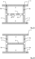
- Fig. 4 and Fig. 5 show a schematic embodiment of a further fire protection glazing 1 for preventing the passage of fire and smoke from one room to another room in the event of fire.
- a plurality of vertically, adjacent and coplanar arranged fire protection panes 2 are each held at their vertical edges by means of two profile elements 3 respectively 3a.
- Each of the profile elements 3 respectively 3a is arranged at each of the vertical edges of the fire protection panes 2.
- the profile elements 3 respectively 3a extend vertically between the floor F and the ceiling C of the rooms.
- Each of the profile elements 3 has a cross section which is substantially rectangular hollow.
- Each of the profile elements 3a has a cross section which is substantially H-shaped. Between the adjacent horizontal edges of the fire protection panes 2 a joint opening 7 is defined.
- the profile elements 3 respectively 3a are made of wood, steel, aluminium and/or concrete.
- the fire protection pane 2 is adhered to the profile element 3 respectively 3a - in the present embodiment to at least one of the two substantially rectangular hollow profile elements 3, preferably to both rectangular hollow profile elements 3 and respectively to at least one of the four free legs of the substantially H-shaped profile elements 3a - by means of glue 6.
- the glue 6 being present all the length of the interface 4 between the surface 5 of the fire protection pane 2 and the profile element 3 respectively 3a such that it provides a glue strip 6a.
- the glue strip 6a has a width W of more than or equal to 10mm and a thickness D of less than 4mm along the length of the interface 4 between the surface 5 of the fire protection pane 2 and the profile element 3 respectively 3a.
- the joint opening 7 between two fire protection panes 2 is closed by sealant 8 only, along the adjacent horizontal edges of the fire protection panes 2.
- the glue strip 6a being continuous along the length of the interface 4 between the surface 5 of a fire protection pane 2 and the profile element 3 respectively 3a.
- the glue 6 is a silicon glue.
- the joint opening 7 between two fire protection panes 2 is closed by a sealant 8 only, which is present along the adjacent horizontal edges of the fire protection panes 2.
- the sealant 8 is a silicon paste.
- the joint 7a between two fire protection panes 2 is provided by a silicon paste 8 only.
- Each fire protection pane 2 is a compound structure of at least two glass panes 9 arranged in parallel to each other, between which in each case at least one fire protection layer 10 is arranged.
- a fire protection pane 2 comprises two glass panes 9 which are spaced apart from each other by means of a spacer 11 providing an edge-compound.
- the spacer 11 is arranged between the two glass panes 9 and extends along the side edges of the fire protection pane 2.
- the edges of the fire protection pane are sealed with a sealing 12.
- the method steps described above in the context of the steps of a method according to Fig. 3a to Fig. 3d are - if needed partly and with other sequences - repeated with/for a further fire protection pane 2, profile element 3 respectively 3a, glue 6, glue strip 6a and/or sealant 8, preferably until the fire protection glazing 1 is present, especially in a way that is reasonably and observant for the person skilled in the art, especially with regard to the parts and/or sequences of the method steps.
Landscapes
- Engineering & Computer Science (AREA)
- Civil Engineering (AREA)
- Structural Engineering (AREA)
- Architecture (AREA)
- Physics & Mathematics (AREA)
- Electromagnetism (AREA)
- Joining Of Glass To Other Materials (AREA)
- Securing Of Glass Panes Or The Like (AREA)
Claims (11)
- Eine Brandschutzverglasung (1) zur Verhinderung des Durchdringens von Feuer und Rauch von einem Raum in einen anderen Raum im Brandfall, mit mindestens zwei Brandschutzscheiben (2) und mindestens zwei Profilelemente (3, 3a),wobei jede Brandschutzscheibe (2) eine Verbundkonstruktion aus mindestens zwei parallel zueinander angeordneten Glasscheiben (9) ist, zwischen denen jeweils mindestens eine Brandschutzschicht (10) angeordnet ist, wobei die Brandschutzscheiben vertikal, nebeneinander und koplanar angeordnet sind und mit nebeneinanderliegenden horizontalen Kanten und mit vertikalen Kanten versehen sind,wobei zwischen den nebeneinanderliegenden horizontalen Kanten der Brandschutzscheiben (2) eine Fugenöffnung (7) definiert ist und die Fugenöffnung (7) zwischen zwei Brandschutzscheiben (2) nur durch Dichtungsmittel (8) entlang der nebeneinanderliegenden horizontalen Kanten der Brandschutzscheiben (2) verschlossen ist,wobei die Brandschutzscheiben (2) an und entlang ihrer vertikalen Kanten mittels der mindestens zwei Profilelemente (3, 3a) gehalten sind, wobei jedes Profilelement (3, 3a) sich in vertikaler Richtung erstreckt und an einer vertikalen Kante einer Brandschutzscheibe (2) angeordnet ist,an jeder Schnittstelle (4) zwischen der Oberfläche (5) einer Brandschutzscheibe (2) und einem Profilelement (3) die Brandschutzscheibe (2) mittels Klebstoff (6) an das Profilelement (3, 3a) angehaftet ist, wobei der Klebstoff (6) über die gesamte Länge der Schnittstelle (4) zwischen der Oberfläche (5) der Brandschutzscheibe (2) und dem Profilelement (3, 3a) vorhanden ist, so dass er einen Klebstoffstreifen (6a) mit einer Breite von mehr als oder gleich 10 mm entlang der Länge der Schnittstelle (4) zwischen der Oberfläche (5) der Brandschutzscheibe (2) und dem Profilelement (3, 3a) bereitstellt,wobei die Brandschutzverglasung nur Profilelemente umfasst, die sich vertikal zwischen dem Boden und der Decke der Räume erstrecken.
- Brandschutzverglasung (1) nach Anspruch 1, dadurch gekennzeichnet, dass der Kleber (6) einen Kleberstreifen (6a) mit einer Breite von mehr als oder gleich 12 mm bildet.
- Brandschutzverglasung (1) nach Anspruch 1 oder 2, dadurch gekennzeichnet, dass der Kleber (6) einen Kleberstreifen (6a) mit einer Breite von 50 mm oder weniger bildet.
- Brandschutzverglasung (1) nach einem der Ansprüche 1 bis 3, dadurch gekennzeichnet, dass der Kleber (6) einen Kleberstreifen (6a) mit einer Dicke von kleiner oder gleich 4mm bildet.
- Brandschutzverglasung (1) nach einem der Ansprüche 1 bis 4, dadurch gekennzeichnet, dass der Klebestreifen (6a) über die gesamte Länge der Schnittstelle (4) zwischen der Oberfläche (5) der Brandschutzscheibe (2) und dem Profilelement (3) durchgehend ist.
- Brandschutzverglasung (1) nach einem der Ansprüche 1 bis 5, dadurch gekennzeichnet, dass die Fugenöffnung (7) zwischen zwei Brandschutzscheiben (2) lediglich durch eine Silikonpaste verschlossen ist.
- Brandschutzverglasung (1) nach Anspruch 1, wobei jedes der Profilelemente (3) einen im Wesentlichen rechteckig-hohlförmigen Querschnitt aufweist.
- Brandschutzverglasung (1) nach Anspruch 1, wobei- die Brandschutzverglasung eine Vielzahl von Brandschutzscheiben umfasst, die in einer ersten und einer zweiten Reihe vertikal benachbarter und koplanarer Brandschutzscheiben mit Profilelementen an und entlang ihrer vertikalen Kanten angeordnet sind,- die Profilelemente (3, 3a) Profilelemente (3) mit einem im Wesentlichen rechteckigen Hohlquerschnitt und Profilelemente (3a) mit einem im Wesentlichen H-förmigen Querschnitt umfassen.
- Brandschutzverglasung (1) nach einem der vorhergehenden Ansprüche, wobei die Brandschutzscheiben an ihren beiden Oberflächen (5) an einer vertikalen Kante mittels mindestens einem Profilelement gehalten sind.
- Verfahren zum Herstellen einer Brandschutzverglasung (1) nach einem der vorhergehenden Ansprüche zum Verhindern des Durchdringens von Feuer und Rauch von einem Raum in einen anderen Raum im Brandfall, umfassend die Schritte:- Bereitstellen von mindestens zwei Profilelementen (3), die sich im Wesentlichen in vertikaler Richtung erstrecken,- Bereitstellen von mindestens zwei Brandschutzscheiben (2),- Anhaften einer ersten der mindestens zwei Brandschutzscheiben (2) in im Wesentlichen vertikaler Richtung an den zwei Profilelementen (3) durch Anbringen eines Klebestreifens (6a) mit einer Breite von mehr als oder gleich 10 mm entlang der Länge der Schnittstelle (4) zwischen der Oberfläche (5) der Brandschutzscheibe (2) und den Profilelementen (3),- Anhaften einer zweiten der mindestens zwei Brandschutzscheiben (2) in im Wesentlichen vertikaler Richtung und koplanar mit der ersten der mindestens zwei Brandschutzscheiben (2) an den zwei Profilelementen (3) durch Anbringen eines Klebestreifens (6a) mit einer Breite von mehr als oder gleich 10 mm entlang der Länge der Schnittstelle (4) zwischen der Oberfläche (5) der Brandschutzscheibe (2) und der Profilelemente (3), wodurch eine Fugenöffnung (7) zwischen den benachbarten horizontalen Kanten der beiden Brandschutzscheiben (2) entsteht,- Verschließen der Fugenöffnung (7) durch ein Dichtmittel (8).
- Verfahren nach Anspruch 10, wobei das Verfahren weiterhin die Schritte umfasst:- vor dem Schritt des Anhaften der zweiten der mindestens zwei Brandschutzscheiben an den mindestens zwei Profilen Anbringen von lastübertragenden Setzklötzen an der horizontalen Kante der ersten der mindestens zwei Brandschutzscheiben und Anbringen der zweiten der mindestens zwei Brandschutzscheiben in Kontakt mit diesen Klötzen,- nach dem Schritt des Anbringens der zweiten der mindestens zwei Brandschutzscheiben (2) an den zwei Profilelementen (3), aber vor dem Schritt des Schließens der Fugenöffnung, Entfernen der lastübertragenden Setzklötze aus dem Inneren der Fugenöffnung.
Priority Applications (1)
| Application Number | Priority Date | Filing Date | Title |
|---|---|---|---|
| EP19169424.9A EP3725993B1 (de) | 2019-04-16 | 2019-04-16 | Brandschutzverglasung |
Applications Claiming Priority (1)
| Application Number | Priority Date | Filing Date | Title |
|---|---|---|---|
| EP19169424.9A EP3725993B1 (de) | 2019-04-16 | 2019-04-16 | Brandschutzverglasung |
Publications (2)
| Publication Number | Publication Date |
|---|---|
| EP3725993A1 EP3725993A1 (de) | 2020-10-21 |
| EP3725993B1 true EP3725993B1 (de) | 2025-04-02 |
Family
ID=66217738
Family Applications (1)
| Application Number | Title | Priority Date | Filing Date |
|---|---|---|---|
| EP19169424.9A Active EP3725993B1 (de) | 2019-04-16 | 2019-04-16 | Brandschutzverglasung |
Country Status (1)
| Country | Link |
|---|---|
| EP (1) | EP3725993B1 (de) |
Family Cites Families (3)
| Publication number | Priority date | Publication date | Assignee | Title |
|---|---|---|---|---|
| US4500572A (en) * | 1983-06-30 | 1985-02-19 | Francis Geoffrey V | Structural spacer glazing with connecting spacer device |
| BE1012820A3 (nl) * | 1998-05-18 | 2001-03-06 | Carlos Desmedt | Modulair bouwsysteem op basis van kunststofelementen en vlakglas of vlakglas-elementen. |
| DE202009002800U1 (de) * | 2009-02-26 | 2009-05-14 | Promat Gmbh | Brandschutzverglasung |
-
2019
- 2019-04-16 EP EP19169424.9A patent/EP3725993B1/de active Active
Also Published As
| Publication number | Publication date |
|---|---|
| EP3725993A1 (de) | 2020-10-21 |
Similar Documents
| Publication | Publication Date | Title |
|---|---|---|
| EP2668360B1 (de) | Anordnungen für eine struktur | |
| EP0136064A2 (de) | Glasverband | |
| US5551195A (en) | Fire-retarding window assembly | |
| NL9401956A (nl) | Beglazingseenheid en werkwijze voor de vervaardiging ervan. | |
| SE501974C2 (sv) | Glasningssystem för byggnader | |
| CN1153889C (zh) | 配有至少两块透光防火玻璃板的止火面积单元 | |
| JPWO2014168219A1 (ja) | 防火複層ガラス | |
| GB2531757A (en) | Spacer Bar to Improve Gas Barrier in Insulated Glass Unit | |
| RU2463429C2 (ru) | Огнеупорное остекление | |
| CA2918653C (en) | Insulating glass with load-bearing properties | |
| TW201814135A (zh) | 強化絕熱玻璃單元 | |
| EP3725993B1 (de) | Brandschutzverglasung | |
| EP3152379B1 (de) | Feuerfeste glasscheibe | |
| AU2016316448B2 (en) | Component made of hollow glass blocks | |
| JP2016142012A (ja) | 複層ガラス体と建具 | |
| JP2019533779A (ja) | シート材料のフレームアセンブリ | |
| US20250020017A1 (en) | Flood Barrier and Method of Use | |
| EP3561189B1 (de) | Trennwand, insbesondere zur schaffung eines brandabschnitts in gebäuderäumen | |
| EP1537288B1 (de) | Satz von rahmen- und flügelabschnitten und elementen in brandsichereren bauten | |
| NO155409B (no) | Innfatningssystem, saerlig til bruk for glass i brannskillevegger. | |
| EP3698001B1 (de) | Gasgefüllte isolierende verglasungseinheit | |
| SE539797C2 (sv) | Anordning vid ett distanselement för åstadkommande av en förbättrad brandisolering vid en skivenhet | |
| JP2008106602A (ja) | 耐火窓 | |
| US20240229471A9 (en) | Building façade constructed of curtain wall panels including fire-safing insulation and method of installation | |
| Rushton | 4.3 Cladding |
Legal Events
| Date | Code | Title | Description |
|---|---|---|---|
| PUAI | Public reference made under article 153(3) epc to a published international application that has entered the european phase |
Free format text: ORIGINAL CODE: 0009012 |
|
| STAA | Information on the status of an ep patent application or granted ep patent |
Free format text: STATUS: THE APPLICATION HAS BEEN PUBLISHED |
|
| AK | Designated contracting states |
Kind code of ref document: A1 Designated state(s): AL AT BE BG CH CY CZ DE DK EE ES FI FR GB GR HR HU IE IS IT LI LT LU LV MC MK MT NL NO PL PT RO RS SE SI SK SM TR |
|
| AX | Request for extension of the european patent |
Extension state: BA ME |
|
| STAA | Information on the status of an ep patent application or granted ep patent |
Free format text: STATUS: REQUEST FOR EXAMINATION WAS MADE |
|
| 17P | Request for examination filed |
Effective date: 20210421 |
|
| RBV | Designated contracting states (corrected) |
Designated state(s): AL AT BE BG CH CY CZ DE DK EE ES FI FR GB GR HR HU IE IS IT LI LT LU LV MC MK MT NL NO PL PT RO RS SE SI SK SM TR |
|
| STAA | Information on the status of an ep patent application or granted ep patent |
Free format text: STATUS: EXAMINATION IS IN PROGRESS |
|
| 17Q | First examination report despatched |
Effective date: 20230626 |
|
| GRAP | Despatch of communication of intention to grant a patent |
Free format text: ORIGINAL CODE: EPIDOSNIGR1 |
|
| STAA | Information on the status of an ep patent application or granted ep patent |
Free format text: STATUS: GRANT OF PATENT IS INTENDED |
|
| INTG | Intention to grant announced |
Effective date: 20241104 |
|
| GRAS | Grant fee paid |
Free format text: ORIGINAL CODE: EPIDOSNIGR3 |
|
| GRAA | (expected) grant |
Free format text: ORIGINAL CODE: 0009210 |
|
| STAA | Information on the status of an ep patent application or granted ep patent |
Free format text: STATUS: THE PATENT HAS BEEN GRANTED |
|
| AK | Designated contracting states |
Kind code of ref document: B1 Designated state(s): AL AT BE BG CH CY CZ DE DK EE ES FI FR GB GR HR HU IE IS IT LI LT LU LV MC MK MT NL NO PL PT RO RS SE SI SK SM TR |
|
| REG | Reference to a national code |
Ref country code: GB Ref legal event code: FG4D |
|
| REG | Reference to a national code |
Ref country code: CH Ref legal event code: EP |
|
| REG | Reference to a national code |
Ref country code: IE Ref legal event code: FG4D |
|
| REG | Reference to a national code |
Ref country code: DE Ref legal event code: R096 Ref document number: 602019068010 Country of ref document: DE |
|
| PGFP | Annual fee paid to national office [announced via postgrant information from national office to epo] |
Ref country code: DE Payment date: 20250422 Year of fee payment: 7 |
|
| PGFP | Annual fee paid to national office [announced via postgrant information from national office to epo] |
Ref country code: GB Payment date: 20250527 Year of fee payment: 7 |
|
| PGFP | Annual fee paid to national office [announced via postgrant information from national office to epo] |
Ref country code: FR Payment date: 20250530 Year of fee payment: 7 |
|
| REG | Reference to a national code |
Ref country code: NL Ref legal event code: MP Effective date: 20250402 |
|
| P01 | Opt-out of the competence of the unified patent court (upc) registered |
Free format text: CASE NUMBER: UPC_APP_1640_3725993/2025 Effective date: 20250731 |
|
| PG25 | Lapsed in a contracting state [announced via postgrant information from national office to epo] |
Ref country code: NL Free format text: LAPSE BECAUSE OF FAILURE TO SUBMIT A TRANSLATION OF THE DESCRIPTION OR TO PAY THE FEE WITHIN THE PRESCRIBED TIME-LIMIT Effective date: 20250402 |
|
| REG | Reference to a national code |
Ref country code: AT Ref legal event code: MK05 Ref document number: 1781418 Country of ref document: AT Kind code of ref document: T Effective date: 20250402 |
|
| PG25 | Lapsed in a contracting state [announced via postgrant information from national office to epo] |
Ref country code: PT Free format text: LAPSE BECAUSE OF FAILURE TO SUBMIT A TRANSLATION OF THE DESCRIPTION OR TO PAY THE FEE WITHIN THE PRESCRIBED TIME-LIMIT Effective date: 20250804 Ref country code: FI Free format text: LAPSE BECAUSE OF FAILURE TO SUBMIT A TRANSLATION OF THE DESCRIPTION OR TO PAY THE FEE WITHIN THE PRESCRIBED TIME-LIMIT Effective date: 20250402 Ref country code: ES Free format text: LAPSE BECAUSE OF FAILURE TO SUBMIT A TRANSLATION OF THE DESCRIPTION OR TO PAY THE FEE WITHIN THE PRESCRIBED TIME-LIMIT Effective date: 20250402 |
|
| REG | Reference to a national code |
Ref country code: LT Ref legal event code: MG9D |
|
| PG25 | Lapsed in a contracting state [announced via postgrant information from national office to epo] |
Ref country code: GR Free format text: LAPSE BECAUSE OF FAILURE TO SUBMIT A TRANSLATION OF THE DESCRIPTION OR TO PAY THE FEE WITHIN THE PRESCRIBED TIME-LIMIT Effective date: 20250703 Ref country code: NO Free format text: LAPSE BECAUSE OF FAILURE TO SUBMIT A TRANSLATION OF THE DESCRIPTION OR TO PAY THE FEE WITHIN THE PRESCRIBED TIME-LIMIT Effective date: 20250702 |
|
| PG25 | Lapsed in a contracting state [announced via postgrant information from national office to epo] |
Ref country code: PL Free format text: LAPSE BECAUSE OF FAILURE TO SUBMIT A TRANSLATION OF THE DESCRIPTION OR TO PAY THE FEE WITHIN THE PRESCRIBED TIME-LIMIT Effective date: 20250402 |
|
| PG25 | Lapsed in a contracting state [announced via postgrant information from national office to epo] |
Ref country code: BG Free format text: LAPSE BECAUSE OF FAILURE TO SUBMIT A TRANSLATION OF THE DESCRIPTION OR TO PAY THE FEE WITHIN THE PRESCRIBED TIME-LIMIT Effective date: 20250402 |
|
| PG25 | Lapsed in a contracting state [announced via postgrant information from national office to epo] |
Ref country code: HR Free format text: LAPSE BECAUSE OF FAILURE TO SUBMIT A TRANSLATION OF THE DESCRIPTION OR TO PAY THE FEE WITHIN THE PRESCRIBED TIME-LIMIT Effective date: 20250402 |
|
| PG25 | Lapsed in a contracting state [announced via postgrant information from national office to epo] |
Ref country code: AT Free format text: LAPSE BECAUSE OF FAILURE TO SUBMIT A TRANSLATION OF THE DESCRIPTION OR TO PAY THE FEE WITHIN THE PRESCRIBED TIME-LIMIT Effective date: 20250402 |
|
| PG25 | Lapsed in a contracting state [announced via postgrant information from national office to epo] |
Ref country code: RS Free format text: LAPSE BECAUSE OF FAILURE TO SUBMIT A TRANSLATION OF THE DESCRIPTION OR TO PAY THE FEE WITHIN THE PRESCRIBED TIME-LIMIT Effective date: 20250702 |
|
| PG25 | Lapsed in a contracting state [announced via postgrant information from national office to epo] |
Ref country code: IS Free format text: LAPSE BECAUSE OF FAILURE TO SUBMIT A TRANSLATION OF THE DESCRIPTION OR TO PAY THE FEE WITHIN THE PRESCRIBED TIME-LIMIT Effective date: 20250802 |
|
| PG25 | Lapsed in a contracting state [announced via postgrant information from national office to epo] |
Ref country code: LV Free format text: LAPSE BECAUSE OF FAILURE TO SUBMIT A TRANSLATION OF THE DESCRIPTION OR TO PAY THE FEE WITHIN THE PRESCRIBED TIME-LIMIT Effective date: 20250402 |
|
| REG | Reference to a national code |
Ref country code: CH Ref legal event code: H13 Free format text: ST27 STATUS EVENT CODE: U-0-0-H10-H13 (AS PROVIDED BY THE NATIONAL OFFICE) Effective date: 20251125 |
|
| PG25 | Lapsed in a contracting state [announced via postgrant information from national office to epo] |
Ref country code: LU Free format text: LAPSE BECAUSE OF NON-PAYMENT OF DUE FEES Effective date: 20250416 |
|
| REG | Reference to a national code |
Ref country code: BE Ref legal event code: MM Effective date: 20250430 |
|
| PG25 | Lapsed in a contracting state [announced via postgrant information from national office to epo] |
Ref country code: SM Free format text: LAPSE BECAUSE OF FAILURE TO SUBMIT A TRANSLATION OF THE DESCRIPTION OR TO PAY THE FEE WITHIN THE PRESCRIBED TIME-LIMIT Effective date: 20250402 Ref country code: DK Free format text: LAPSE BECAUSE OF FAILURE TO SUBMIT A TRANSLATION OF THE DESCRIPTION OR TO PAY THE FEE WITHIN THE PRESCRIBED TIME-LIMIT Effective date: 20250402 |
|
| PG25 | Lapsed in a contracting state [announced via postgrant information from national office to epo] |
Ref country code: BE Free format text: LAPSE BECAUSE OF NON-PAYMENT OF DUE FEES Effective date: 20250430 |
|
| PG25 | Lapsed in a contracting state [announced via postgrant information from national office to epo] |
Ref country code: CH Free format text: LAPSE BECAUSE OF NON-PAYMENT OF DUE FEES Effective date: 20250430 |
|
| PG25 | Lapsed in a contracting state [announced via postgrant information from national office to epo] |
Ref country code: CZ Free format text: LAPSE BECAUSE OF FAILURE TO SUBMIT A TRANSLATION OF THE DESCRIPTION OR TO PAY THE FEE WITHIN THE PRESCRIBED TIME-LIMIT Effective date: 20250402 |
|
| PG25 | Lapsed in a contracting state [announced via postgrant information from national office to epo] |
Ref country code: EE Free format text: LAPSE BECAUSE OF FAILURE TO SUBMIT A TRANSLATION OF THE DESCRIPTION OR TO PAY THE FEE WITHIN THE PRESCRIBED TIME-LIMIT Effective date: 20250402 |
|
| PG25 | Lapsed in a contracting state [announced via postgrant information from national office to epo] |
Ref country code: RO Free format text: LAPSE BECAUSE OF FAILURE TO SUBMIT A TRANSLATION OF THE DESCRIPTION OR TO PAY THE FEE WITHIN THE PRESCRIBED TIME-LIMIT Effective date: 20250402 Ref country code: SK Free format text: LAPSE BECAUSE OF FAILURE TO SUBMIT A TRANSLATION OF THE DESCRIPTION OR TO PAY THE FEE WITHIN THE PRESCRIBED TIME-LIMIT Effective date: 20250402 |
|
| PG25 | Lapsed in a contracting state [announced via postgrant information from national office to epo] |
Ref country code: IT Free format text: LAPSE BECAUSE OF FAILURE TO SUBMIT A TRANSLATION OF THE DESCRIPTION OR TO PAY THE FEE WITHIN THE PRESCRIBED TIME-LIMIT Effective date: 20250402 |
|
| PG25 | Lapsed in a contracting state [announced via postgrant information from national office to epo] |
Ref country code: MC Free format text: LAPSE BECAUSE OF FAILURE TO SUBMIT A TRANSLATION OF THE DESCRIPTION OR TO PAY THE FEE WITHIN THE PRESCRIBED TIME-LIMIT Effective date: 20250402 |
|
| PLBE | No opposition filed within time limit |
Free format text: ORIGINAL CODE: 0009261 |
|
| STAA | Information on the status of an ep patent application or granted ep patent |
Free format text: STATUS: NO OPPOSITION FILED WITHIN TIME LIMIT |
|
| REG | Reference to a national code |
Ref country code: CH Ref legal event code: L10 Free format text: ST27 STATUS EVENT CODE: U-0-0-L10-L00 (AS PROVIDED BY THE NATIONAL OFFICE) Effective date: 20260211 |