EP3725668B1 - Energiespeicherponton, schiff, schifffahrtssystem und verfahren zum betreiben des schifffahrtssystems - Google Patents
Energiespeicherponton, schiff, schifffahrtssystem und verfahren zum betreiben des schifffahrtssystems Download PDFInfo
- Publication number
- EP3725668B1 EP3725668B1 EP20170050.7A EP20170050A EP3725668B1 EP 3725668 B1 EP3725668 B1 EP 3725668B1 EP 20170050 A EP20170050 A EP 20170050A EP 3725668 B1 EP3725668 B1 EP 3725668B1
- Authority
- EP
- European Patent Office
- Prior art keywords
- anolyte
- catholyte
- tank
- ship
- pontoon
- Prior art date
- Legal status (The legal status is an assumption and is not a legal conclusion. Google has not performed a legal analysis and makes no representation as to the accuracy of the status listed.)
- Active
Links
Images


Classifications
-
- B—PERFORMING OPERATIONS; TRANSPORTING
- B63—SHIPS OR OTHER WATERBORNE VESSELS; RELATED EQUIPMENT
- B63H—MARINE PROPULSION OR STEERING
- B63H21/00—Use of propulsion power plant or units on vessels
- B63H21/12—Use of propulsion power plant or units on vessels the vessels being motor-driven
- B63H21/17—Use of propulsion power plant or units on vessels the vessels being motor-driven by electric motor
-
- H—ELECTRICITY
- H01—ELECTRIC ELEMENTS
- H01M—PROCESSES OR MEANS, e.g. BATTERIES, FOR THE DIRECT CONVERSION OF CHEMICAL ENERGY INTO ELECTRICAL ENERGY
- H01M8/00—Fuel cells; Manufacture thereof
- H01M8/04—Auxiliary arrangements, e.g. for control of pressure or for circulation of fluids
- H01M8/04082—Arrangements for control of reactant parameters, e.g. pressure or concentration
- H01M8/04186—Arrangements for control of reactant parameters, e.g. pressure or concentration of liquid-charged or electrolyte-charged reactants
-
- H—ELECTRICITY
- H01—ELECTRIC ELEMENTS
- H01M—PROCESSES OR MEANS, e.g. BATTERIES, FOR THE DIRECT CONVERSION OF CHEMICAL ENERGY INTO ELECTRICAL ENERGY
- H01M8/00—Fuel cells; Manufacture thereof
- H01M8/04—Auxiliary arrangements, e.g. for control of pressure or for circulation of fluids
- H01M8/04082—Arrangements for control of reactant parameters, e.g. pressure or concentration
- H01M8/04201—Reactant storage and supply, e.g. means for feeding, pipes
-
- H—ELECTRICITY
- H01—ELECTRIC ELEMENTS
- H01M—PROCESSES OR MEANS, e.g. BATTERIES, FOR THE DIRECT CONVERSION OF CHEMICAL ENERGY INTO ELECTRICAL ENERGY
- H01M8/00—Fuel cells; Manufacture thereof
- H01M8/04—Auxiliary arrangements, e.g. for control of pressure or for circulation of fluids
- H01M8/04276—Arrangements for managing the electrolyte stream, e.g. heat exchange
-
- H—ELECTRICITY
- H01—ELECTRIC ELEMENTS
- H01M—PROCESSES OR MEANS, e.g. BATTERIES, FOR THE DIRECT CONVERSION OF CHEMICAL ENERGY INTO ELECTRICAL ENERGY
- H01M8/00—Fuel cells; Manufacture thereof
- H01M8/18—Regenerative fuel cells, e.g. redox flow batteries or secondary fuel cells
- H01M8/184—Regeneration by electrochemical means
- H01M8/188—Regeneration by electrochemical means by recharging of redox couples containing fluids; Redox flow type batteries
-
- B—PERFORMING OPERATIONS; TRANSPORTING
- B63—SHIPS OR OTHER WATERBORNE VESSELS; RELATED EQUIPMENT
- B63B—SHIPS OR OTHER WATERBORNE VESSELS; EQUIPMENT FOR SHIPPING
- B63B35/00—Vessels or similar floating structures specially adapted for specific purposes and not otherwise provided for
- B63B35/44—Floating buildings, stores, drilling platforms, or workshops, e.g. carrying water-oil separating devices
- B63B2035/4433—Floating structures carrying electric power plants
-
- B—PERFORMING OPERATIONS; TRANSPORTING
- B63—SHIPS OR OTHER WATERBORNE VESSELS; RELATED EQUIPMENT
- B63J—AUXILIARIES ON VESSELS
- B63J3/00—Driving of auxiliaries
- B63J2003/001—Driving of auxiliaries characterised by type of power supply, or power transmission, e.g. by using electric power or steam
- B63J2003/002—Driving of auxiliaries characterised by type of power supply, or power transmission, e.g. by using electric power or steam by using electric power
-
- B—PERFORMING OPERATIONS; TRANSPORTING
- B63—SHIPS OR OTHER WATERBORNE VESSELS; RELATED EQUIPMENT
- B63J—AUXILIARIES ON VESSELS
- B63J3/00—Driving of auxiliaries
- B63J3/04—Driving of auxiliaries from power plant other than propulsion power plant
- B63J2003/043—Driving of auxiliaries from power plant other than propulsion power plant using shore connectors for electric power supply from shore-borne mains, or other electric energy sources external to the vessel, e.g. for docked, or moored vessels
-
- H—ELECTRICITY
- H01—ELECTRIC ELEMENTS
- H01M—PROCESSES OR MEANS, e.g. BATTERIES, FOR THE DIRECT CONVERSION OF CHEMICAL ENERGY INTO ELECTRICAL ENERGY
- H01M2220/00—Batteries for particular applications
- H01M2220/20—Batteries in motive systems, e.g. vehicle, ship, plane
-
- Y—GENERAL TAGGING OF NEW TECHNOLOGICAL DEVELOPMENTS; GENERAL TAGGING OF CROSS-SECTIONAL TECHNOLOGIES SPANNING OVER SEVERAL SECTIONS OF THE IPC; TECHNICAL SUBJECTS COVERED BY FORMER USPC CROSS-REFERENCE ART COLLECTIONS [XRACs] AND DIGESTS
- Y02—TECHNOLOGIES OR APPLICATIONS FOR MITIGATION OR ADAPTATION AGAINST CLIMATE CHANGE
- Y02E—REDUCTION OF GREENHOUSE GAS [GHG] EMISSIONS, RELATED TO ENERGY GENERATION, TRANSMISSION OR DISTRIBUTION
- Y02E60/00—Enabling technologies; Technologies with a potential or indirect contribution to GHG emissions mitigation
- Y02E60/10—Energy storage using batteries
-
- Y—GENERAL TAGGING OF NEW TECHNOLOGICAL DEVELOPMENTS; GENERAL TAGGING OF CROSS-SECTIONAL TECHNOLOGIES SPANNING OVER SEVERAL SECTIONS OF THE IPC; TECHNICAL SUBJECTS COVERED BY FORMER USPC CROSS-REFERENCE ART COLLECTIONS [XRACs] AND DIGESTS
- Y02—TECHNOLOGIES OR APPLICATIONS FOR MITIGATION OR ADAPTATION AGAINST CLIMATE CHANGE
- Y02E—REDUCTION OF GREENHOUSE GAS [GHG] EMISSIONS, RELATED TO ENERGY GENERATION, TRANSMISSION OR DISTRIBUTION
- Y02E60/00—Enabling technologies; Technologies with a potential or indirect contribution to GHG emissions mitigation
- Y02E60/30—Hydrogen technology
- Y02E60/50—Fuel cells
Definitions
- the invention relates to a shipping system including an energy storage pontoon and a ship as well as to a method for the operating of the shipping system.
- KR20170092783 relates to a ship of modular construction which is provided with a first block and a second block each containing an electrolyte tank. Further, the ship is provided with a block which is provided with a flow battery and a screw propeller. This drive block is detachably connectible with the first and the second block.
- AU2011101353 discloses in Figure 3 a system of a number of ships which includes tanks with anolyte and catholyte. These ships sail back and forth between an oil rig and the shore. At the oil rig lies a ship which is provided with cell stacks which are connected to a gas turbine generator with which waste gas from the oil rig is converted into electricity and with which the anolyte and the catholyte can be electrically charged. Onshore, there is also a so-called onshore discharge cell stack which anolyte and catholyte from the ship are passed through for generating electric power which is fed into the public electricity grid or a load.
- KR20180104354 relates to a ship which is provided with electrolyte tanks movable on rails, for these tanks to serve as ballast tanks with which the ship can be trimmed.
- gases that are released on the ship for example in oil storage tanks, can be converted in a fuel cell into electricity which can be supplied to the public electricity grid. Also, power may be drawn from this public electricity grid to charge the electrolytes again via the stacks.
- CN108565486 describes a ship which is provided with electrolyte tanks. When the electrolytes in them are discharged, they can be pumped from the tanks to a shore-based charging platform. The electrolytes are therefore not recharged onboard the ship but onshore in an installation which is on shore to that end.
- the object of the invention is to provide a solution to the above-described issues.
- the invention provides shipping system according to claim 1.
- One element of the shipping system of the invention is at least one energy storage pontoon which comprises a floating pontoon shell with:
- Such an energy storage pontoon can in fact be placed anywhere without prolonged permit procedures needing to be traversed for this. None of the publications mentioned above in the background section describes a pontoon for storing anolyte and catholyte and for electrically charging or electrically discharging the anolyte and catholyte with the aid of a flow battery, while the pontoon is connected with the quay only via a power cable and for the rest no liquid lines or like connections with the shore are necessary.
- a pontoon is a floating shell which is not provided with a drive of its own such as a screw driven by a motor. Pontoons are generally conveyed to a point of destination with the aid of a towboat or like vessel and moored there.
- KR'783 and KR'354 describe ships - no pontoons - where charging the electrolytes takes place on the ship. In consequence, for a longer time, the ship is not available for transporting cargo.
- AU'353 en CN'486 describe ships that are provided with facilities for filling or emptying the electrolyte tanks present therein by pumping.
- the electric charging or discharging of the electrolytes takes place on shore. That, accordingly, requires an extensive installation on shore, which moreover cannot be realized just anywhere. This is due both to practical considerations based on technical problems - not everywhere is there a suitable quay on which the cell stacks can be placed - and to issues connected with permits - in many places no permit will be issued to construct a stack onshore. It is to be borne in mind here that a cell stack with a fair capacity takes up a substantial floor surface. Moreover, the processing, such as the pumping, of electrolytes onshore requires special safety measures in view of the environment.
- the only thing that needs to be provided from the shore is an electric cable which is connectible to the electric connection of the energy storage pontoon.
- the electric cable is obviously preferred for the electric cable to be connected with an electric source of the sustainable type, such as, for example, a windmill park, a photovoltaic source, such as for example a solar panel meadow, a water turbine which is for instance incorporated in a lock, or a like source of clean energy.
- the electric cable is connected with the general electricity grid. Also combinations of the two are among the options.
- a single anolyte tank and a single catholyte tank there can be a single anolyte tank and a single catholyte tank.
- anolyte is withdrawn on a first side of the anolyte tank and recirculated via the anode chamber to a second side of the anolyte tank.
- a similar kind of recirculation, in this variant, is also carried out with the catholyte which is passed from a first side of the catholyte tank via the cathode chamber to a second side of the catholyte tank.
- anolyte will be pumped from the first anolyte tank to the second anolyte tank via the anode chamber of the flow battery and the second anolyte tank is filled with liquid, charged anolyte.
- discharged catholyte will be pumped from the first catholyte tank to the second catholyte tank via the cathode chamber of the flow battery and the second catholyte tank is filled with liquid, charged catholyte.
- the energy storage pontoon can also be used in support of the electricity grid. For instance, in days of little wind and/or little sunshine, the charged anolyte and charged catholyte stored in the tanks can be pumped again via respectively the anode chamber and the cathode chamber of the flow battery. With the first above-discussed variant, there will be recirculation then too. With the second above-discussed variant, the anolyte will then be pumped from the second anolyte tank to the first anolyte tank and the catholyte will be pumped from the second catholyte tank to the first catholyte tank.
- the electric energy thereby released can be delivered to the electricity grid, for example to serve as a primary reserve or Frequency Containment Reserve (FCR) for stabilizing the electricity grid and for peak shaving.
- FCR Frequency Containment Reserve
- the anolyte and the catholyte are stored in tanks in an energy storage pontoon because such a pontoon can in fact be moored anywhere, so long as an electricity cable is available from the shore to feed electric energy given a surplus of electricity production and possibly carry off electricity given a demand for electricity in the electricity grid.
- the anolyte and the catholyte can then serve as fuel for electrically driven ships which are provided with a flow battery.
- Another part of the shipping system of the invention is at least one ship. More particularly, the ship of the shipping system is provided with a hull with:
- Such a ship functions in virtually the same way as a ship which is provided with a diesel engine. Also for the ship of the shipping system according to the invention, it holds there can be two variants.
- the ship has per flow battery one anolyte tank and one catholyte tank.
- the anolyte is recirculated by the anolyte pump from a first side of the anolyte tank via the anode chamber to a second side of the anolyte tank.
- the catholyte is recirculated by the catholyte pump from a first side of the catholyte tank via the cathode chamber to a second side of the catholyte tank.
- the ship has at least one first anolyte tank for holding charged anolyte and at least one second anolyte tank for holding discharged anolyte. Moreover, in that second variant, the ship has at least one first catholyte tank for holding charged catholyte and at least one second catholyte tank for holding discharged catholyte.
- this filling up consists in first pumping out the anolyte tank and catholyte tank, so that the discharged anolyte and catholyte are removed therefrom and then refilling the anolyte tank and catholyte tank with charged anolyte and charged catholyte.
- filling up means that not only the at least one first anolyte tank and the at least one first catholyte tank are filled with charged anolyte and catholyte respectively, but also that the at least one second anolyte tank with discharged anolyte and the at least one second catholyte tank with discharged catholyte is emptied.
- a shipping system may be provided including a bunker ship.
- the bunker ship of this shipping system embodiment may be provided with a bunker ship supply tank for holding charged anolyte, a bunker ship supply tank for holding charged catholyte, a bunker ship supply tank for holding discharged anolyte, and a bunker ship supply tank for holding discharged catholyte.
- the bunker ship supply tanks for charged anolyte and charged catholyte can be filled from, respectively, the at least one anolyte tank and the at least one catholyte tank of the energy storage pontoon which are filled with charged anolyte and charged catholyte.
- bunker ship supply tanks for charged anolyte and charged catholyte will generally be emptied at ships that need to be provided with new "fuel”.
- the bunker ship supply tanks for discharged anolyte and discharged catholyte will generally be filled at ships and be emptied at the energy storage pontoon.
- a shipping system according to the invention it is possible to sail entirely CO 2 -neutrally, for example for the purpose of transporting containers or bulk material.
- a shipping system is particularly favorable.
- Such inland vessels or barges have sufficient space for storing anolyte and catholyte in the associated anolyte tank and catholyte tank.
- the shipping system according to the invention constitutes a considerable contribution to the realization of the climate targets which are currently greatly valued.
- the shipping system is also applicable to ocean shipping, short sea shipping and the like.
- the invention provides a method according to claim 15 for the operating of shipping system.
- the method comprises for the purpose of charging the anolyte and the catholyte:
- the method according to the invention therefore describes the charging of the discharged anolyte and the discharged catholyte and the filling of the at least one anolyte tank and the at least one catholyte tank of the energy storage pontoon with charged anolyte and charged catholyte.
- This method is carried out when electric power is available for this.
- the electric power is furnished by renewable energy sources, such as wind and solar energy.
- the method can, for the purpose of supplying electric power, further comprise:
- the energy storage pontoon then serves as a primary reserve or frequency containment reserve (FCR).
- FCR frequency containment reserve
- the pontoon can also be applied for peak shaving.
- the energy storage pontoon and the method according to the invention can make a contribution to the stabilization of the electricity grid and also supply fuel for the ships according to the invention which are part of a shipping system according to the invention.
- the invention provides a shipping system including an energy storage pontoon 10 which comprises a floating pontoon shell 12.
- An example of an energy storage pontoon 10 is represented in Figures 1 , 2 , 5 , and 6 .
- the energy storage pontoon 10 further comprises at least one flow battery 22 which includes an anode chamber 24 provided with an anode 26, a cathode chamber 28 provided with a cathode 30, and a membrane 32 which separates the anode chamber 24 from the cathode chamber 28.
- the energy storage pontoon 10 has an anolyte fill opening 34 via which the at least one anolyte tank 14 is fillable with a liquid, discharged anolyte, and the energy storage pontoon 10 has a catholyte fill opening 36 via which the at least one catholyte tank 16 is fillable with a liquid, discharged catholyte.
- the energy storage pontoon 10 further has an anolyte delivery provision 38 via which charged anolyte can be delivered from the at least one anolyte tank 14 or 18, as well as a catholyte delivery provision 40 via which charged catholyte can be delivered from the at least one catholyte tank 16 or 20.
- At least one anolyte line 42 connects the at least one anolyte tank 14 with the anode chamber 24.
- At least one catholyte line 44 connects the at least one catholyte tank 16 with the cathode chamber 28.
- At least one anolyte pump 46 is included with the aid of which anolyte is pumpable from the at least one anolyte tank 14 via the anode chamber 24 of the flow battery 22 to the at least one anolyte tank 14 or 18.
- At least one catholyte pump 48 is included with the aid of which anolyte is pumpable from the at least one catholyte tank 16 via the cathode chamber 28 of the flow battery 22 to the at least one catholyte tank 16 or 20.
- the energy storage pontoon 10 is provided with at least one electric connection 50 for electrically connecting the flow battery 22 with an electric source P and/or electric load L.
- the at least one flow battery 22 is associated with a single anolyte tank 14 and a single catholyte tank 16.
- the anolyte is pumped around through the circuit which is formed by the anolyte line 42 having included therein the anolyte tank 14, the anode chamber 24 and the anolyte pump 46.
- the catholyte is pumped around through the circuit which is formed by the catholyte line 44 having included therein the catholyte tank 18, cathode chamber 28 and catholyte pump 48.
- the at least one anolyte tank 14, 18 comprises at least one first anolyte tank 14 for holding liquid, discharged anolyte and at least one second anolyte tank 18 for holding liquid, charged anolyte.
- the at least one catholyte tank 16, 20 comprises at least one first catholyte tank 16 for holding liquid, discharged catholyte and at least one second catholyte tank 20 for holding liquid, charged catholyte.
- the anolyte fill opening 34 is connected to the at least one first anolyte tank 14 which is fillable with a liquid, discharged anolyte.
- the catholyte fill opening 36 is connected to the at least one first catholyte tank 16 which is fillable with a liquid discharged catholyte.
- the anolyte delivery provision 38 is connected to the at least one second anolyte tank 18.
- the catholyte delivery provision 40 is connected to the at least one second catholyte tank 20.
- the at least one anolyte line 42 connects the at least one first anolyte tank 14 via the anode chamber 24 with the at least one second anolyte tank 18.
- the at least one catholyte line 44 connects the at least one first catholyte tank 16 via the cathode chamber 28 with the at least one second catholyte tank 20.
- anolyte is pumpable from the at least one first anolyte tank 14 via the anode chamber 24 of the flow battery 22 to the at least one second anolyte tank 18.
- catholyte is pumpable from the at least one first catholyte tank 16 via the cathode chamber 28 of the flow battery 22 to the at least one second catholyte tank 20.
- An advantage of this embodiment is that the filling of the at least one first anolyte tank 14 and the at least one first catholyte tank 16 with discharged anolyte and catholyte can take place concurrently with the delivery of charged anolyte and charged catholyte from the at least one second anolyte tank 18 and the at least one second catholyte tank 20.
- the at least one anolyte tank 14 and if present 18 and the at least one catholyte tank 16 and if present 20 of the energy storage pontoon 10 are provided on an inner side with a coating, for example a dielectric coating.
- Such a coating protects the tanks, which may be made, for example, from metal, against corrosion by the anolyte and the catholyte. Moreover, leaking away of charge is minimized by the dielectric coating.
- the at least one anolyte tank 14 and if present 18 and the at least one catholyte tank 16 and if present 20 of the energy storage pontoon 10 are made from plastic. It is then preferred that the plastic is dielectric.
- plastic tanks have the advantage of the electricity-insulating action, so that leaking away of charge is minimized.
- the energy storage pontoon 10 of the shipping system may be further provided with a storage area for battery containers and with electric connections with the aid of which battery containers can be connected with the general electric connection 50 of the energy storage pontoon 10. It is possible with this embodiment to charge battery containers with the aid of the energy storage pontoon 10. This charging can take place directly from the electric source P, but it is also possible that the electric charge for the purpose of the charging of the battery containers is withdrawn from the charged anolyte and catholyte by pumping the charged anolyte through the anode chamber 24 and by pumping the charged catholyte through the cathode chamber 28. The electric energy thereby released can thereupon be stored in the battery containers.
- the storage area may be formed, for example, by an upper deck of the energy storage pontoon 10.
- the energy storage pontoon 10 may be displaced with the aid of a tugboat and possibly may itself be provided with a drive so that it can move itself without help of tugboats.
- the pontoon is provided with spud poles 52 connected in a manner movable up and down with the pontoon shell 12.
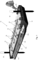
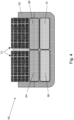
- the shipping system further comprises at least one ship 60 of which an example is shown in Figures 3 , 4 , 5 and 6 .
- the ship 60 In the hull 62 of the ship 60 are at least one anolyte tank 64 for holding liquid anolyte and at least one catholyte tank 66 for holding liquid catholyte.
- the ship 60 further comprises at least one flow battery 72 which includes an anode chamber 74 provided with an anode 76, a cathode chamber 78 provided with a cathode 80, and a membrane 82 which separates the anode chamber 74 from the cathode chamber 78.
- the ship 60 has an anolyte fill opening 84 via which the at least one anolyte tank 64 is fillable with a liquid charged anolyte, and the ship 60 has a catholyte fill opening 86 via which the at least one catholyte tank 66 is fillable with a liquid charged catholyte.
- the ship 60 also has an anolyte removal provision 88 via which discharged anolyte can be removed from the at least one anolyte tank 64 or 68, and has a catholyte removal provision 90 via which discharged catholyte can be removed from the at least one catholyte tank 66 or 70.
- the ship 60 is provided with at least one anolyte line 92 which connects the at least one anolyte tank 64 with the anode chamber 74.
- the ship 60 also has at least one catholyte line 94 which connects the at least one catholyte tank 66 with the cathode chamber 78.
- at least one anolyte pump 96 is included, with the aid of which anolyte is pumpable from the at least one anolyte tank 64 via the anode chamber 74 of the flow battery 72 to one of the at least one anolyte tank 64 or 68.
- the ship 60 has at least one electric motor 100 for driving of at least one screw of the ship 60.
- the electric motor 100 is electrically connected with the flow battery 72.
- the at least one flow battery 72 of the ship 60 is associated with a single anolyte tank 64 and a single catholyte tank 66 of the ship.
- the anolyte is pumped around through the circuit which is formed by the anolyte line 92 having included therein the anolyte tank 64, the anode chamber 74 and the anolyte pump 96
- the catholyte is pumped around through the circuit which is formed by the catholyte line 94 having included therein the catholyte tank 66, cathode chamber 78 and catholyte pump 98.
- the at least one anolyte tank of the ship 60 comprises at least one first anolyte tank 64 for holding liquid, charged anolyte and at least one second anolyte tank 68 for holding liquid, discharged anolyte.
- the at least one catholyte tank of the ship 60 comprises at least one first catholyte tank 66 for holding liquid, charged catholyte and at least one second catholyte tank 70 for holding liquid, discharged catholyte.
- the anolyte fill opening 84 is connected to the at least one first anolyte tank 64 of the ship 60 which is fillable with a liquid charged anolyte.
- the catholyte fill opening 86 is connected to the at least one first catholyte tank 66 of the ship 60 which is fillable with a liquid charged catholyte.
- the anolyte removal provision 88 is connected to the at least one second anolyte tank 68 of the ship 60, whereby with the aid of the anolyte removal provision 88, discharged anolyte can be removed from the at least one second anolyte tank 68.
- the catholyte removal provision 90 is connected to the at least one second catholyte tank 70 of the ship 60, whereby with the aid of the catholyte removal provision 90, discharged catholyte can be removed from the at least one second catholyte tank 70 of the ship 60.
- the at least one anolyte line 92 connects the at least one first anolyte tank 64 via the anode chamber 74 with the at least one second anolyte tank 68 of the ship 60.
- the at least one catholyte line 94 connects the at least one first catholyte tank 66 via the cathode chamber 78 with the at least one second catholyte tank 70 of the ship 60.
- anolyte is pumpable from the at least one first anolyte tank 64 via the anode chamber 74 of the flow battery 72 to the at least one second anolyte tank 68.
- catholyte is pumpable from the at least one first catholyte tank 66 via the cathode chamber 78 of the flow battery 72 to the at least one second catholyte tank 70.
- An advantage of this embodiment is that removal of discharged anolyte and catholyte from the at least one second anolyte tank 68 and the at least one second catholyte tank 70 can take place concurrently with the filling of the at least one first anolyte tank 64 and the at least one first catholyte tank 66 with charged anolyte and charged catholyte.
- the ship 60 can hence continue on its way more quickly.
- the at least one anolyte tank 64 and if present 68 of the ship 60 and the at least one catholyte tank 66 and if present 70 of the ship 60 may be provided on an inner side with a coating, for example a dielectric coating.
- the at least one anolyte tank 64 and if present 68 of the ship 60, and the at least one catholyte tank 66 and if present 70 of the ship 60 are made from plastic.
- the plastic may then be dielectric.
- Both embodiments have the advantage that leaking away of electric charge from the charged anolyte and the charged catholyte is kept to the minimum in the ship 60 and that, moreover, corrosion of the tanks is hindered.
- the ship 60 may be provided with a connection 102 for electrically connecting the flow battery 72 of the ship 60 with an electric source P and/or electric load L.
- This embodiment provides the advantage that when no bunker ship 110 or energy storage pontoon 10 is available, the "fuel" of the ship can yet be brought into a usable condition again by connecting the electric connection 102 with an electric source P, for example on shore. A voltage is thereby applied to the anode 76 and the cathode 80 of the flow battery 72. The discharged anolyte and catholyte can then be pumped through the flow battery 72 of the ship 60. During the passage of respectively the anode chamber 74 and the cathode chamber 78 of the flow battery 72 of the ship, the anolyte and the catholyte are brought from the discharged into the charged condition. Thereupon, the ship 60 can continue its journey without having tanked up liquid but instead the ship has tanked up electric power and converted it into chemical potential energy which is stored in the charged anolyte and catholyte.
- the ship can be an inland vessel or barge 60.
- Especially barges 60 have sufficient storage space for accommodating the at least one anolyte tank 64 and if present 68 and the catholyte tanks 66 and if present 70.
- such tanks 64, 66, 68, 70 only account for a small part of the space that is available in an inland barge 60.
- a ship of the shipping system can be a bunker ship 110.
- An example of such a bunker ship 110 is shown in Figures 1 and 5 .
- the bunker ship 110 comprises a bunker ship supply tank 112 for holding charged anolyte, a bunker ship supply tank 114 for holding charged catholyte, a bunker ship supply tank 116 for holding discharged anolyte, and a bunker ship supply tank 118 for holding discharged catholyte.
- the bunker ship 110 may be provided with an anolyte delivery provision which comprises a second anolyte line 120 and a second anolyte pump 122 for pumping charged anolyte from the bunker ship supply tank 112 for charged anolyte to an anolyte tank 64 of a user.
- the bunker ship may then further have a catholyte delivery provision which comprises a second catholyte line 124 and a second catholyte pump 126 for pumping charged catholyte from the bunker ship supply tank 114 for charged catholyte to a catholyte tank 66 of a user.
- a thus-implemented bunker ship 110 has the advantage that no external pumps are necessary to be able to deliver charged anolyte and charged catholyte to, for example, the first anolyte tank 64 and the first catholyte tank 66 of a ship 60.
- the bunker ship 110 according to this embodiment can therefore function in exactly the same manner as a conventional bunker ship which delivers diesel oil to ships.
- the bunker ship may be provided with an anolyte receiving provision which comprises a third anolyte line 128 and a third anolyte pump 130 for pumping discharged anolyte from an anolyte tank 68 of a user to the bunker ship supply tank 116 for discharged anolyte.
- the bunker ship 110 may then further have a catholyte receiving provision which comprises a third catholyte line 132 and a third catholyte pump 134 for pumping discharged catholyte from a catholyte tank of a user to the bunker ship supply tank 118 for discharged catholyte.
- a thus-implemented bunker ship 110 can pump out the at least one anolyte tank 64 and if present 68 and the at least one catholyte tank 66 and if present 70.
- the ship 60 itself does not need to have a pump to pump out the at least one anolyte tank 64 and if present 68 and the at least one catholyte tank 66 and if present 70.
- the invention does not exclude a ship 60 being provided with its own pumps for emptying the at least one anolyte tank 64 or 68 and the at least one catholyte tank 66 or 70.
- the shipping system comprises a bunker ship 110
- fuel that is, charged anolyte and charged catholyte
- ships 60 that cannot reach the energy storage pontoon 10 or in respect of which it is found unfavorable to have them navigate to the energy storage pontoon 10, for example for economic reasons or accessibility reasons.
- the invention provides a method for the operating of shipping system.
- the method comprises for the purpose of charging the anolyte and the catholyte:
- the method comprises for the purpose of supplying electric power:
- the energy storage pontoon 10 there is provided to the energy storage pontoon 10 an additional function besides the function of production and supply of fuel for ships 60.
- the energy storage pontoon 10 can meet this extra demand with the aid of the application of the present embodiment of the method.
- the method comprises:
- the method further comprises:
- This embodiment in fact describes supplying of charged anolyte and catholyte to a ship 60 or a bunker ship 110.
- the method can further comprise:
- This embodiment describes the taking up of discharged anolyte and discharged catholyte from, for example, a ship 60.
- the method can further comprise:
- This embodiment concerns supplying of charged anolyte and charged catholyte from the bunker ship 110.
- the method can further comprise:
- This embodiment concerns the bunker ship 110 receiving discharged anolyte and discharged catholyte.
Landscapes
- Chemical & Material Sciences (AREA)
- Engineering & Computer Science (AREA)
- Chemical Kinetics & Catalysis (AREA)
- Sustainable Development (AREA)
- Sustainable Energy (AREA)
- Manufacturing & Machinery (AREA)
- Life Sciences & Earth Sciences (AREA)
- Electrochemistry (AREA)
- General Chemical & Material Sciences (AREA)
- Combustion & Propulsion (AREA)
- Mechanical Engineering (AREA)
- Ocean & Marine Engineering (AREA)
- Fuel Cell (AREA)
Claims (22)
- Schifffahrtssystem, das Folgendes umfasst:- mindestens einen Energiespeicherponton (10) und- mindestens ein Schiff (60);wobei der mindestens eine Energiespeicherponton (10) des Schifffahrtssystems Folgendes umfasst:- eine schwimmende Pontonhülle (12) mit:wobei der Energiespeicherponton ferner Folgendes umfasst:• mindestens einem Anolyttank (14; 14, 18) zum Aufnehmen flüssigen Anolyts;• mindestens einen Katholyttank (16; 16, 20) zum Aufnehmen flüssigen Katholyts;- mindestens eine Flow-Batterie (22), die Folgendes beinhaltet:wobei der Energiespeicherponton (10) ferner mit Folgendem versehen ist:• eine Anodenkammer (24), die mit einer Anode (26)) versehen ist;• eine Kathodenkammer (28), die mit einer Kathode (30) versehen ist;• eine Membran (32), die die Anodenkammer (24) von der Kathodenkammer (28) trennt;- eine Anolytfüllöffnung (34), über die der mindestens eine Anolyttank (14; 14, 18) mit einem flüssigen, entladenen Anolyt befüllbar ist;- eine Katholytfüllöffnung (36), über die mindestens ein Katholyttank (16; 16, 20) mit einem flüssigen, entladenen Katholyt befüllbar ist;- eine Anolytabgabevorrichtung (38), über die aufgeladener Anolyt aus dem mindestens einen Anolyttank (14; 18) abgegeben werden kann; und- eine Katholytabgabevorrichtung (40), über die aufgeladener Katholyt aus dem mindestens einen Katholyttank (16; 20) abgegeben werden kann;- mindestens eine Katholytleitung (42), die den mindestens einen Anolyttank (14; 14, 18) mit der Anodenkammer (24) verbindet;- mindestens eine Katholytleitung (44), die den mindestens einen Katholyttank (16; 16, 20) mit der Kathodenkammer (28) verbindet;- mindestens eine Anolytpumpe (46), die in der Anolytleitung (42) beinhaltet ist und mit deren Hilfe der Anolyt aus dem mindestens einen Anolyttank (14) über die Anodenkammer (24) der Flow-Batterie (22) zu dem mindestens einen Anolyttank (14; 18) pumpbar ist;- mindestens eine Katholytpumpe (48), die in der Katholytleitung (44) beinhaltet ist und mit deren Hilfe der Katholyt aus dem mindestens einen Katholyttank (16) über die Kathodenkammer (28) der Flow-Batterie (22) zu dem mindestens einen Katholyttank (16; 20) pumpbar ist; und- mindestens eine Stromverbindung (50), um die Flow-Batterie mit einer Stromquelle (22) und/oder einem Stromverbraucher (L) zu verbinden;- wobei der mindestens eine Energiespeicherponton mit einer Stromquelle (P) über die mindestens eine Stromverbindung (50) verbunden ist, wobei die Stromquelle (P) beispielsweise das Elektrizitätsnetz oder ein Kraftwerk ist,wobei das mindestens eine Schiff des Schifffahrtssystems Folgendes umfasst:- einen Rumpf (62) mit:wobei das Schiff (60) ferner Folgendes umfasst:• mindestens einem Anolyttank (64; 64, 68) zum Aufnehmen flüssigen Anolyts;• mindestens einem Katholyttank (66; 66, 70) zum Aufnehmen flüssigen Katholyts;- mindestens eine Flow-Batterie (72), die Folgendes beinhaltet:wobei das Schiff ferner mit Folgendem versehen ist:• eine Anodenkammer (74), die mit einer Anode (76)) versehen ist;• eine Kathodenkammer (78), die mit einer Kathode (80) versehen ist;• eine Membran (82), die die Anodenkammer (74) von der Kathodenkammer (78) trennt;- eine Anolytfüllöffnung (84), über die der mindestens eine Anolyttank (64) mit einem flüssigen, aufgeladenen Anolyt befüllbar ist;- eine Katholytfüllöffnung (86), über die der mindestens eine Katholyttank (66) mit einem flüssigen, aufgeladenen Katholyt befüllbar ist;- eine Anolytentfernungsvorrichtung (88), über die entladener Anolyt aus dem mindestens einen Anolyttank (64; 68) entfernt werden kann; und- eine Katholytentfernungsvorrichtung (90), über die entladener Katholyt aus dem mindestens einen Katholyttank (66; 70) entfernt werden kann;- mindestens eine Anolytleitung (92), die den mindestens einen Anolyttank (64; 64, 68) mit der Anodenkammer (74) verbindet;- mindestens eine Katholytleitung (94), die den mindestens einen Katholyttank (66; 66, 70) mit der Kathodenkammer (78) verbindet;- mindestens eine Anolytpumpe (96), die in der Anolytleitung (92) beinhaltet ist und mit deren Hilfe der Anolyt aus dem mindestens einen Anolyttank (64) über die Anodenkammer (74) der Flow-Batterie (72) zu einem des mindestens einen Anolyttanks (64; 68) pumpbar ist; und- mindestens eine Katholytpumpe (98), die in der Katholytleitung (94) beinhaltet ist und mit deren Hilfe der Katholyt aus dem mindestens einen Katholyttank (66) über die Kathodenkammer (78) der Flow-Batterie (72) zu einem des mindestens einen Katholyttanks (66; 70) pumpbar ist;- mindestens einen Elektromotor (100) zum Antreiben mindestens einer Schraube des Schiffs (60), wobei der Elektromotor (100) mit der Flow-Batterie (72) verbunden ist.
- Schifffahrtssystem nach Anspruch 1, wobei der mindestens eine Anolyttank (14; 18) des Energiespeicherpontons (10) Folgendes umfasst:- mindestens einen ersten Anolyttank (14) zum Aufnehmen flüssigen, entladenen Anolyts;- mindestens einen zweiten Anolyttank (18) zum Aufnehmen flüssigen, aufgeladenen Anolyts;und wobei der mindestens eine Katholyttanks (16, 20) des Energiespeicherpontons (10) Folgendes umfasst:- mindestens einen ersten Katholyttank (16) zum Aufnehmen flüssigen, entladenen Katholyts;- mindestens einen zweiten Katholyttank (20) zum Aufnehmen flüssigen, aufgeladenen Katholyts;wobei die Anolytfüllöffnung (34) mit dem mindestens einen ersten Anolyttank (14) verbunden ist, der mit einem flüssigen entladenen Anolyt befüllbar ist;wobei die Katholytfüllöffnung (36) mit dem mindestens einen ersten Katholyttank (16) verbunden ist, der mit einem flüssigen, entladenen Katholyt befüllbar ist;wobei die Anolytabgabevorrichtung (38) mit dem mindestens einen zweiten Anolyttank (18) verbunden ist; undwobei die Kathodenabgabevorrichtung (40) mit dem mindestens einen zweiten Katholyttank (20) verbunden ist;wobei die mindestens eine Anolytleitung (42) den mindestens einen ersten Anolyttank (14) über die Anodenkammer (24) mit dem mindestens einen zweiten Anolyttank (18) verbindet;wobei die mindestens eine Katholytleitung (44) den mindestens einen ersten Katholyttank (16) über die Kathodenkammer (28) mit dem mindestens einen zweiten Katholyttank (20) verbindet;wobei mit Hilfe der mindestens einen Anolytpumpe (46) Anolyt aus dem mindestens einen ersten Anolyttank (14) über die Anodenkammer (24) der Flow-Batterie (22) zu dem mindestens einen zweiten Anolyttank (18) pumpbar ist;wobei mit Hilfe der mindestens einen Katholytpumpe (48) Katholyt aus dem mindestens einen ersten Katholyttank (16) über die Kathodenkammer (28) der Flow-Batterie (22) zu dem mindestens einen zweiten Katholyttank (20) pumpbar ist.
- Schifffahrtssystem nach Anspruch 1 oder 2, wobei der mindestens eine Anolyttank (14; 14, 18) des Energiespeicherpontons (10) und der mindestens eine Katholyttank (16; 16, 20) des Energiespeicherpontons (10) an einer Innenseite mit einer Beschichtung, beispielsweise einer dielektrischen Beschichtung, versehen sind.
- Schifffahrtssystem nach Anspruch 1 oder 2, wobei der mindestens eine Anolyttank (14; 14, 18) und der mindestens eine Katholyttank (16; 16, 20) des Energiespeicherpontons (10) aus Kunststoff hergestellt sind.
- Schifffahrtssystem nach Anspruch 4, wobei der Kunststoff dielektrisch ist.
- Schifffahrtssystem nach einem der Ansprüche 1 bis 5, wobei der mindestens eine Anolyttank des Schiffs Folgendes umfasst:- mindestens einen ersten Anolyttank (64) zum Aufnehmen flüssigen, aufgeladenen Anolyts;- mindestens einen zweiten Anolyttank (68) zum Aufnehmen flüssigen, entladenen Anolyts;und wobei der mindestens eine Katholyttank des Schiffs Folgendes umfasst:- mindestens einen ersten Katholyttank (66) zum Aufnehmen flüssigen, aufgeladenen Katholyts;- mindestens einen zweiten Katholyttank (70) zum Aufnehmen flüssigen, entladenen Katholyts;wobei die Anolytfüllöffnung (84) des Schiffs mit dem mindestens einen ersten Anolyttank (64) des Schiffs verbunden ist, der mit einem flüssigen aufgeladenen Anolyt befüllbar ist;wobei die Katholytfüllöffnung (86) des Schiffs mit dem mindestens einen ersten Katholyttank (66) des Schiffs verbunden ist, der mit einem flüssigen aufgeladenen Katholyt befüllbar ist;wobei die Anolytentfernungsvorrichtung (88) mit dem mindestens einen zweiten Anolyttank (68) des Schiffs verbunden ist, wobei mit Hilfe der Anolytentfernungsvorrichtung (88) entladener Anolyt aus dem mindestens einen zweiten Anolyttank (68) des Schiffs entfernt werden kann; undwobei die Katholytentfernungsvorrichtung (90) mit dem zweiten Katholyttank (70) des Schiffs verbunden ist, wobei mit Hilfe der Katholytentfernungsvorrichtung (90) entladener Katholyt aus dem mindestens einen zweiten Katholyttank (70) des Schiffs entfernt werden kann;wobei die mindestens eine Anolytleitung (92) den mindestens einen ersten Anolyttank (64) über die Anodenkammer (74) mit dem mindestens einen zweiten Anolyttank (68) des Schiffs verbindet;wobei die mindestens eine Katholytleitung (94) den mindestens einen ersten Katholyttank (66) über die Kathodenkammer (78) mit dem mindestens einen zweiten Katholyttank (70) des Schiffs verbindet;wobei mit Hilfe der mindestens einen Anolytpumpe (96) Anolyt aus dem mindestens einen ersten Anolyttank (64) über die Anodenkammer (74) der Flow-Batterie (72) zu dem mindestens einen zweiten Anolyttank (68) des Schiffs pumpbar ist; undwobei mit Hilfe der mindestens einen Katholytpumpe (98) Katholyt aus dem mindestens einen ersten Katholyttank (66) über die Kathodenkammer (78) der Flow-Batterie (72) zu dem mindestens einen zweiten Katholyttank (70) pumpbar ist.
- Schifffahrtssystem nach einem der Ansprüche 1 bis 6, wobei der mindestens eine Anolyttank (64; 64, 68) des Schiffs und der mindestens eine Katholyttank (66; 66, 70) des Schiffs an einer Innenseite mit einer Beschichtung, beispielsweise einer dielektrischen Beschichtung, versehen sind.
- Schifffahrtssystem nach einem der Ansprüche 1 bis 7, wobei der mindestens eine Anolyttank (64; 64, 68) und der mindestens eine Katholyttank (66; 66, 70) aus Kunststoff hergestellt sind.
- Schifffahrtssystem nach Anspruch 8, wobei der Kunststoff dielektrisch ist.
- Schifffahrtssystem nach einem der Ansprüche 1 bis 9, wobei das Schiff (60) mit einer Verbindung (102) zum elektrischen Verbinden der Flow-Batterie (72) des Schiffs (60) mit einer Stromquelle (P) und/oder einem Stromverbraucher (L) versehen ist.
- Schifffahrtssystem nach einem der Ansprüche 1 bis 10, wobei das Schiff ein Binnenschiff (60) ist.
- Schifffahrtssystem nach einem der Ansprüche 1 bis 11, wobei das mindestens eine Schiff mindestens zwei Schiffe umfasst, von welchen mindestens ein Schiff ein Bunkerschiff (110) ist, wobei das Bunkerschiff (110) Folgendes umfasst:- einen Bunkerschiff-Versorgungstank (112) zum Aufnehmen aufgeladenen Anolyts,- einen Bunkerschiff-Versorgungstank (114) zum Aufnehmen aufgeladenen Katholyts,- einen Bunkerschiff-Versorgungstank (116) zum Aufnehmen entladenen Anolyts, und- einen Bunkerschiff-Versorgungstank (118) zum Aufnehmen entladenen Katholyts.
- Schifffahrtssystem nach Anspruch 12, wobei das Schifffahrtssystem (110) Folgendes umfasst:- eine Anolytabgabevorrichtung, die eine zweite Anolytleitung (120) und eine zweite Anolytpumpe (122) zum Pumpen aufgeladenen Anolyts aus dem Bunkerschiff-Versorgungstank (112) für aufgeladenen Anolyt zu einem Anolyttank (64) für einen Benutzer umfasst.- eine Katholytabgabevorrichtung, die eine zweite Katholytleitung (124) und eine zweite Katholytpumpe (126) zum Pumpen aufgeladenen Katholyts aus dem Bunkerschiff-Versorgungstank (114) für aufgeladenen Katholyt zu einem Katholyttank (66) eines Benutzers umfasst.
- Schifffahrtssystem nach Anspruch 13, wobei das Bunkerschiff (110) Folgendes umfasst:- eine Anolytempfangsvorrichtung, die eine dritte Anolytleitung (128) und eine dritte Anolytpumpe (130) zum Pumpen entladenen Anolyts aus einem Anolyttank eines Benutzers zu dem Bunkerschiff-Versorgungstank (116) für entladenen Anolyts umfasst; und- eine Katholytempfangsvorrichtung, die eine dritte Katholytleitung (132) und eine dritte Katholytpumpe (134) zum Pumpen entladenen Katholyts aus einem Katholyttank eines Benutzers zu dem Bunkerschiff-Versorgungstank (118) für entladenen Katholyt umfasst.
- Schifffahrtbetriebsverfahren, wobei das Verfahren zum Zweck des Aufladens des Anolyts und des Katholyts Folgendes umfasst:- das Bereitstellen eines erfindungsgemäßen Schifffahrtssystems nach einem der Ansprüche 1 bis 14, wobei von dem Energiespeicherponton (10) der mindestens eine Anolyttank (14; 14, 18) mindestens teilweise mit flüssigen Anolyt befüllt wird, und wobei der mindestens eine Katholyttank (16; 16, 20) mindestens teilweise mit flüssigem Katholyt befüllt wird;- das Verbinden der Stromverbindung (50) des Energiespeicherpontons (10) mit einer Stromquelle (P);- mit Hilfe der Anolytpumpe (46), das Pumpen von Anolyt aus dem mindestens einen Anolyttank (14) über die Anodenkammer (24) der mindestens einen Flow-Batterie (22) zu einem des mindestens einen Anolyttanks (14; 18);- mit Hilfe der Katholytpumpe (48), das Pumpen von Katholyt aus dem mindestens einen Katholyttank (16) über die Kathodenkammer (28) der mindestens einen Flow-Batterie (22) zu einem des mindestens einen Katholyttanks (16; 20).
- Verfahren nach Anspruch 15, wobei das Verfahren zum Zweck des Zuführens von elektrischem Strom Folgendes umfasst:- das Verbinden der Stromverbindung (50) des Energiespeicherpontons (10) mit einem Stromverbraucher (L);- mit Hilfe der Anolytpumpe (46), das Pumpen von Anolyt aus dem mindestens einen Anolyttank (14) über die Anodenkammer (24) der mindestens einen Flow-Batterie (22) zu einem des mindestens einen Anolyttanks (14; 18);- mit Hilfe der Katholytpumpe (48), das Pumpen von Katholyt aus dem mindestens einen Katholyttank (16) über die Kathodenkammer (28) der mindestens einen Flow-Batterie (22) zu einem des mindestens einen Katholyttanks (16; 20).
- Verfahren nach Anspruch 15 oder 16, wobei das Schifffahrtssystem nach Anspruch 2 implementiert wird, wobei der mindestens eine erste Anolyttank (14) des Energiespeicherpontons (10) mindestens teilweise mit flüssigem, entladenem Anolyt, befüllt wird, der mindestens eine erste Katholyttank (16) des Energiespeicherpontons (10) mindestens teilweise mit flüssigem, entladenem Katholyt befüllt wird, der mindestens eine zweite Anolyttank (18) des Energiespeicherpontons (10) mindestens teilweise mit flüssigem, aufgeladenem Anolyt befüllt wird, und der mindestens eine zweite Katholyttank (20) des Energiespeicherponton (10) mindestens teilweise mit flüssigem, aufgeladenem Katholyt befüllt wird;
wobei das Verfahren Folgendes umfasst:- mit Hilfe der Anolytpumpe (46), Pumpen entladenen Anolyts aus dem ersten Anolyttank (14) über die Anodenkammer (24) der mindestens einen Flow-Batterie (22) zu dem zweiten Anolyttank (18), wenn über die Stromverbindung (50) elektrischer Strom von der Stromquelle (P) verfügbar ist;- mit Hilfe der Katholytpumpe (48), Pumpen entladenen Katholyts aus dem ersten Katholyttank (16) über die Kathodenkammer (28) der mindestens einen Flow-Batterie (22) zu dem zweiten Katholyttank (20), wenn über die Stromverbindung (50) elektrischer Strom von der Stromquelle (P) verfügbar ist. - Verfahren nach Anspruch 17, das ferner Folgendes umfasst:- mit Hilfe der Anolytpumpe (46) des Energiespeicherpontons (10), Pumpen aufgeladenen Anolyts aus dem zweiten Anolyttank (18) über die Anodenkammer (24) der mindestens einen Flow-Batterie (22) zu dem ersten Anolyttank (14) des Energiespeicherpontons (10), wenn Strom über die Stromverbindung (50) von dem Stromverbraucher (L) verlangt wird;- mit Hilfe der Katholytpumpe (48) des Energiespeicherpontons (10), Pumpen aufgeladenen Katholyts aus dem zweiten Anolyttank (20) über die Kathodenkammer (28) der mindestens einen Flow-Batterie (22) zu dem ersten Katholyttank (16) des Energiespeicherpontons (10), wenn elektrischer Strom über die Stromverbindung (50) von dem Stromverbraucher (L) verlangt wird.
- Verfahren nach einem der Ansprüche 15 bis 18, das ferner Folgendes umfasst:- über die Anolytabgabevorrichtung (38), Zuführen aufgeladenen Anolyts zu einem Anolyttank (64) eines Schiffs (60) oder zu einem Bunkerschiff-Versorgungstank (112) für aufgeladenen Anolyt;- über die Kathodenabgabevorrichtung (40), Zuführen aufgeladenen Katholyts zu einem Katholyttank (66) eines Schiffs (60) oder zu einem Bunkerschiff-Versorgungstank (114) für aufgeladenen Katholyt.
- Verfahren nach einem der Ansprüche 15 bis 19, das ferner Folgendes umfasst:- über die Anolytfüllöffnung (34), Einspeisen entladenen Anolyts zu dem mindestens einen Anolyttank (14) des Energiespeicherpontons (10); und- über die Katholytfüllöffnung (36), Einspeisen entladenen Katholyts zu dem mindestens einen Katholyttank (16) des Energiespeicherpontons (10).
- Verfahren nach einem der Ansprüche 15 bis 20, wobei das Schifffahrtssystem einem der Ansprüche 13-14 entspricht, einschließlich des Verwendens des Bunkerschiffs (110), wobei das Verfahren ferner Folgendes umfasst:- mit Hilfe der zweiten Anolytpumpe (122), über die zweite Anolytleitung (120), Pumpen aufgeladenen Anolyts aus dem Bunkerschiff-Versorgungstank (112) zu dem Anolyttank (64) eines Schiffs (60) des Schifffahrtssystems; und- mit Hilfe der zweiten Katholytpumpe (126), über die zweite Katholytleitung (124), Pumpen aufgeladenen Katholyts aus dem Bunkerschiff-Versorgungstank (114) für aufgeladenen Katholyt zu dem Katholyttank (66) eines Schiffs (60) des Schifffahrtssystems.
- Verfahren nach einem der Ansprüche 15 bis 21, wobei das Schifffahrtssystem Anspruch 14 entspricht, einschließlich des Verwendens des Bunkerschiffs (110), wobei das Verfahren ferner Folgendes umfasst:- mit Hilfe der dritten Anolytpumpe (130), über die dritte Anolytleitung (128), Pumpen entladenen Anolyts aus dem Anolyttank (64) oder (68) des Schiffs (60) zu dem Bunkerschiff-Versorgungstank (116) für entladenen Anolyt;- mit Hilfe der dritten Katholytpumpe (134), über die dritte Katholytleitung (132), Pumpen entladenen Katholyts aus dem Katholyttank (66 oder 70) des Schiffs (60) zu dem Bunkerschiff-Versorgungstank (118) für entladenen Katholyt.
Applications Claiming Priority (1)
| Application Number | Priority Date | Filing Date | Title |
|---|---|---|---|
| NL2022980A NL2022980B1 (nl) | 2019-04-18 | 2019-04-18 | Een energie-opslag-ponton, een schip, een scheepvaartsysteem en een werkwijze voor het bedrijven van het scheepvaartsystem. |
Publications (3)
| Publication Number | Publication Date |
|---|---|
| EP3725668A1 EP3725668A1 (de) | 2020-10-21 |
| EP3725668B1 true EP3725668B1 (de) | 2024-09-18 |
| EP3725668C0 EP3725668C0 (de) | 2024-09-18 |
Family
ID=66380103
Family Applications (1)
| Application Number | Title | Priority Date | Filing Date |
|---|---|---|---|
| EP20170050.7A Active EP3725668B1 (de) | 2019-04-18 | 2020-04-17 | Energiespeicherponton, schiff, schifffahrtssystem und verfahren zum betreiben des schifffahrtssystems |
Country Status (2)
| Country | Link |
|---|---|
| EP (1) | EP3725668B1 (de) |
| NL (1) | NL2022980B1 (de) |
Families Citing this family (3)
| Publication number | Priority date | Publication date | Assignee | Title |
|---|---|---|---|---|
| DK202100447A1 (en) * | 2021-04-30 | 2022-11-21 | A P Moeller Mærsk As | Bunker system and bunker station |
| DK202100446A1 (en) * | 2021-04-30 | 2022-11-16 | A P Moeller Mærsk As | Battery system and hull assembly |
| WO2023229548A1 (en) * | 2022-05-25 | 2023-11-30 | Yenice Aylin | Improvement of the portable floating trimaran caravan |
Family Cites Families (6)
| Publication number | Priority date | Publication date | Assignee | Title |
|---|---|---|---|---|
| CN101257121B (zh) * | 2007-03-02 | 2012-08-22 | 新南创新私人有限公司 | 用于钒液流电池组的电极和电解液的制备方法以及再平衡方法 |
| ES2429359T3 (es) | 2010-04-27 | 2013-11-14 | Sumitomo Electric Industries, Ltd. | Batería de flujo redox |
| AU2011101353A4 (en) * | 2011-10-21 | 2012-02-02 | Jayaram, Narsimhan Mr | Method of capturing stranded natural gas and flare gas energy by means of redox electrolyte transfer |
| KR20170092783A (ko) * | 2016-02-04 | 2017-08-14 | 삼성중공업 주식회사 | 블록형 바지선 |
| KR101933682B1 (ko) * | 2017-03-13 | 2018-12-31 | 삼성중공업 주식회사 | 선박 |
| CN108565486B (zh) * | 2018-04-28 | 2021-01-01 | 湖南省银峰新能源有限公司 | 一种钒电池货轮储电系统及充电方法 |
-
2019
- 2019-04-18 NL NL2022980A patent/NL2022980B1/nl active
-
2020
- 2020-04-17 EP EP20170050.7A patent/EP3725668B1/de active Active
Also Published As
| Publication number | Publication date |
|---|---|
| EP3725668C0 (de) | 2024-09-18 |
| NL2022980B1 (nl) | 2020-10-26 |
| EP3725668A1 (de) | 2020-10-21 |
Similar Documents
| Publication | Publication Date | Title |
|---|---|---|
| EP3626598B1 (de) | Emissionsfreies stromerzeugungssegelschiff | |
| EP3725668B1 (de) | Energiespeicherponton, schiff, schifffahrtssystem und verfahren zum betreiben des schifffahrtssystems | |
| AU2011356248B2 (en) | Floating or submerging device with an electrolyser | |
| Hasvold et al. | The alkaline aluminium/hydrogen peroxide power source in the Hugin II unmanned underwater vehicle | |
| CN101842566B (zh) | 能漂浮的港口电源 | |
| US10577067B1 (en) | Zero emission power generation sailing ship | |
| EP3922545A1 (de) | Wasserfahrzeug zur herstellung von wasserstoff an bord aus erneuerbaren quellen | |
| EP3919369A1 (de) | Behälter zur entsalzung von salzwasser, umwandlung desselben in trinkwasser und erzeugung von elektrischer energie | |
| KR20190058117A (ko) | 선박의 발전 시스템 및 방법 | |
| NL2027667B1 (en) | Floatable wind turbine for producing hydrogen | |
| US20060071630A1 (en) | Hybrid power system | |
| GB2383204A (en) | Offshore wind driven generator | |
| Cherchi et al. | Electrification of commercial vessels: Pilot projects and open issues | |
| KR20100105902A (ko) | 자율형 동적 항해 선체 | |
| KR20170012015A (ko) | 발전 범선 및 수소 생산 공급 시스템 | |
| CN115347549B (zh) | 一种电动船舶上液流电池储能系统及控制方法 | |
| CN115056958B (zh) | 一种以全钒液流电池为动力的运输船舶及其运行方法 | |
| KR102517199B1 (ko) | 해양그린수소의 생산, 저장 및 이송을 위한 해상플랫폼 | |
| CN115276195B (zh) | 一种以全钒液流电池为动力的运输船舶的充电系统及其运行方法 | |
| CN109703727A (zh) | 一种大容量浮式电池储能船 | |
| US20240213503A1 (en) | Bunker system and bunker station | |
| KR20260045255A (ko) | 컨테이너 배터리 및 연료 모듈 교체형 하이브리드 전기 추진 선박 | |
| WO2018208143A1 (en) | System for transferring energy | |
| KR20240004393A (ko) | 배터리 시스템 및 선체 조립체 | |
| JP2026021355A (ja) | 海洋再生可能エネルギー収穫システム |
Legal Events
| Date | Code | Title | Description |
|---|---|---|---|
| PUAI | Public reference made under article 153(3) epc to a published international application that has entered the european phase |
Free format text: ORIGINAL CODE: 0009012 |
|
| STAA | Information on the status of an ep patent application or granted ep patent |
Free format text: STATUS: THE APPLICATION HAS BEEN PUBLISHED |
|
| AK | Designated contracting states |
Kind code of ref document: A1 Designated state(s): AL AT BE BG CH CY CZ DE DK EE ES FI FR GB GR HR HU IE IS IT LI LT LU LV MC MK MT NL NO PL PT RO RS SE SI SK SM TR |
|
| AX | Request for extension of the european patent |
Extension state: BA ME |
|
| STAA | Information on the status of an ep patent application or granted ep patent |
Free format text: STATUS: REQUEST FOR EXAMINATION WAS MADE |
|
| 17P | Request for examination filed |
Effective date: 20210421 |
|
| RBV | Designated contracting states (corrected) |
Designated state(s): AL AT BE BG CH CY CZ DE DK EE ES FI FR GB GR HR HU IE IS IT LI LT LU LV MC MK MT NL NO PL PT RO RS SE SI SK SM TR |
|
| STAA | Information on the status of an ep patent application or granted ep patent |
Free format text: STATUS: EXAMINATION IS IN PROGRESS |
|
| 17Q | First examination report despatched |
Effective date: 20221201 |
|
| P01 | Opt-out of the competence of the unified patent court (upc) registered |
Effective date: 20230508 |
|
| GRAP | Despatch of communication of intention to grant a patent |
Free format text: ORIGINAL CODE: EPIDOSNIGR1 |
|
| STAA | Information on the status of an ep patent application or granted ep patent |
Free format text: STATUS: GRANT OF PATENT IS INTENDED |
|
| INTG | Intention to grant announced |
Effective date: 20240416 |
|
| GRAS | Grant fee paid |
Free format text: ORIGINAL CODE: EPIDOSNIGR3 |
|
| GRAA | (expected) grant |
Free format text: ORIGINAL CODE: 0009210 |
|
| STAA | Information on the status of an ep patent application or granted ep patent |
Free format text: STATUS: THE PATENT HAS BEEN GRANTED |
|
| AK | Designated contracting states |
Kind code of ref document: B1 Designated state(s): AL AT BE BG CH CY CZ DE DK EE ES FI FR GB GR HR HU IE IS IT LI LT LU LV MC MK MT NL NO PL PT RO RS SE SI SK SM TR |
|
| REG | Reference to a national code |
Ref country code: GB Ref legal event code: FG4D |
|
| REG | Reference to a national code |
Ref country code: CH Ref legal event code: EP |
|
| REG | Reference to a national code |
Ref country code: DE Ref legal event code: R096 Ref document number: 602020037798 Country of ref document: DE |
|
| REG | Reference to a national code |
Ref country code: IE Ref legal event code: FG4D |
|
| U01 | Request for unitary effect filed |
Effective date: 20241014 |
|
| P04 | Withdrawal of opt-out of the competence of the unified patent court (upc) registered |
Free format text: CASE NUMBER: APP_58875/2024 Effective date: 20241028 |
|
| U07 | Unitary effect registered |
Designated state(s): AT BE BG DE DK EE FI FR IT LT LU LV MT NL PT RO SE SI Effective date: 20241031 |
|
| PG25 | Lapsed in a contracting state [announced via postgrant information from national office to epo] |
Ref country code: NO Free format text: LAPSE BECAUSE OF FAILURE TO SUBMIT A TRANSLATION OF THE DESCRIPTION OR TO PAY THE FEE WITHIN THE PRESCRIBED TIME-LIMIT Effective date: 20241218 |
|
| PG25 | Lapsed in a contracting state [announced via postgrant information from national office to epo] |
Ref country code: GR Free format text: LAPSE BECAUSE OF FAILURE TO SUBMIT A TRANSLATION OF THE DESCRIPTION OR TO PAY THE FEE WITHIN THE PRESCRIBED TIME-LIMIT Effective date: 20241219 |
|
| PG25 | Lapsed in a contracting state [announced via postgrant information from national office to epo] |
Ref country code: HR Free format text: LAPSE BECAUSE OF FAILURE TO SUBMIT A TRANSLATION OF THE DESCRIPTION OR TO PAY THE FEE WITHIN THE PRESCRIBED TIME-LIMIT Effective date: 20240918 |
|
| PG25 | Lapsed in a contracting state [announced via postgrant information from national office to epo] |
Ref country code: RS Free format text: LAPSE BECAUSE OF FAILURE TO SUBMIT A TRANSLATION OF THE DESCRIPTION OR TO PAY THE FEE WITHIN THE PRESCRIBED TIME-LIMIT Effective date: 20241218 |
|
| PG25 | Lapsed in a contracting state [announced via postgrant information from national office to epo] |
Ref country code: RS Free format text: LAPSE BECAUSE OF FAILURE TO SUBMIT A TRANSLATION OF THE DESCRIPTION OR TO PAY THE FEE WITHIN THE PRESCRIBED TIME-LIMIT Effective date: 20241218 Ref country code: NO Free format text: LAPSE BECAUSE OF FAILURE TO SUBMIT A TRANSLATION OF THE DESCRIPTION OR TO PAY THE FEE WITHIN THE PRESCRIBED TIME-LIMIT Effective date: 20241218 Ref country code: HR Free format text: LAPSE BECAUSE OF FAILURE TO SUBMIT A TRANSLATION OF THE DESCRIPTION OR TO PAY THE FEE WITHIN THE PRESCRIBED TIME-LIMIT Effective date: 20240918 Ref country code: GR Free format text: LAPSE BECAUSE OF FAILURE TO SUBMIT A TRANSLATION OF THE DESCRIPTION OR TO PAY THE FEE WITHIN THE PRESCRIBED TIME-LIMIT Effective date: 20241219 |
|
| PG25 | Lapsed in a contracting state [announced via postgrant information from national office to epo] |
Ref country code: IS Free format text: LAPSE BECAUSE OF FAILURE TO SUBMIT A TRANSLATION OF THE DESCRIPTION OR TO PAY THE FEE WITHIN THE PRESCRIBED TIME-LIMIT Effective date: 20250118 |
|
| PG25 | Lapsed in a contracting state [announced via postgrant information from national office to epo] |
Ref country code: SM Free format text: LAPSE BECAUSE OF FAILURE TO SUBMIT A TRANSLATION OF THE DESCRIPTION OR TO PAY THE FEE WITHIN THE PRESCRIBED TIME-LIMIT Effective date: 20240918 |
|
| PG25 | Lapsed in a contracting state [announced via postgrant information from national office to epo] |
Ref country code: ES Free format text: LAPSE BECAUSE OF FAILURE TO SUBMIT A TRANSLATION OF THE DESCRIPTION OR TO PAY THE FEE WITHIN THE PRESCRIBED TIME-LIMIT Effective date: 20240918 |
|
| PG25 | Lapsed in a contracting state [announced via postgrant information from national office to epo] |
Ref country code: PL Free format text: LAPSE BECAUSE OF FAILURE TO SUBMIT A TRANSLATION OF THE DESCRIPTION OR TO PAY THE FEE WITHIN THE PRESCRIBED TIME-LIMIT Effective date: 20240918 Ref country code: CZ Free format text: LAPSE BECAUSE OF FAILURE TO SUBMIT A TRANSLATION OF THE DESCRIPTION OR TO PAY THE FEE WITHIN THE PRESCRIBED TIME-LIMIT Effective date: 20240918 |
|
| PG25 | Lapsed in a contracting state [announced via postgrant information from national office to epo] |
Ref country code: SK Free format text: LAPSE BECAUSE OF FAILURE TO SUBMIT A TRANSLATION OF THE DESCRIPTION OR TO PAY THE FEE WITHIN THE PRESCRIBED TIME-LIMIT Effective date: 20240918 |
|
| U20 | Renewal fee for the european patent with unitary effect paid |
Year of fee payment: 6 Effective date: 20250428 |
|
| PLBE | No opposition filed within time limit |
Free format text: ORIGINAL CODE: 0009261 |
|
| STAA | Information on the status of an ep patent application or granted ep patent |
Free format text: STATUS: NO OPPOSITION FILED WITHIN TIME LIMIT |
|
| 26N | No opposition filed |
Effective date: 20250619 |
|
| REG | Reference to a national code |
Ref country code: CH Ref legal event code: H13 Free format text: ST27 STATUS EVENT CODE: U-0-0-H10-H13 (AS PROVIDED BY THE NATIONAL OFFICE) Effective date: 20251125 |
|
| PG25 | Lapsed in a contracting state [announced via postgrant information from national office to epo] |
Ref country code: MC Free format text: LAPSE BECAUSE OF FAILURE TO SUBMIT A TRANSLATION OF THE DESCRIPTION OR TO PAY THE FEE WITHIN THE PRESCRIBED TIME-LIMIT Effective date: 20240918 |
|
| GBPC | Gb: european patent ceased through non-payment of renewal fee |
Effective date: 20250417 |
|
| PG25 | Lapsed in a contracting state [announced via postgrant information from national office to epo] |
Ref country code: GB Free format text: LAPSE BECAUSE OF NON-PAYMENT OF DUE FEES Effective date: 20250417 |
|
| PG25 | Lapsed in a contracting state [announced via postgrant information from national office to epo] |
Ref country code: CH Free format text: LAPSE BECAUSE OF NON-PAYMENT OF DUE FEES Effective date: 20250430 |
|
| PG25 | Lapsed in a contracting state [announced via postgrant information from national office to epo] |
Ref country code: IE Free format text: LAPSE BECAUSE OF NON-PAYMENT OF DUE FEES Effective date: 20250417 |