EP3725654A1 - Conveyor system, rail and production system - Google Patents
Conveyor system, rail and production system Download PDFInfo
- Publication number
- EP3725654A1 EP3725654A1 EP19174645.2A EP19174645A EP3725654A1 EP 3725654 A1 EP3725654 A1 EP 3725654A1 EP 19174645 A EP19174645 A EP 19174645A EP 3725654 A1 EP3725654 A1 EP 3725654A1
- Authority
- EP
- European Patent Office
- Prior art keywords
- support rail
- rail
- conveyor system
- run
- area
- Prior art date
- Legal status (The legal status is an assumption and is not a legal conclusion. Google has not performed a legal analysis and makes no representation as to the accuracy of the status listed.)
- Granted
Links
- 238000004519 manufacturing process Methods 0.000 title claims description 30
- 238000012546 transfer Methods 0.000 claims description 20
- 239000000725 suspension Substances 0.000 claims description 10
- 238000011282 treatment Methods 0.000 claims description 6
- 238000012545 processing Methods 0.000 claims description 5
- 238000012423 maintenance Methods 0.000 claims description 4
- 230000008439 repair process Effects 0.000 claims description 4
- XAGFODPZIPBFFR-UHFFFAOYSA-N aluminium Chemical compound [Al] XAGFODPZIPBFFR-UHFFFAOYSA-N 0.000 claims description 2
- 229910052782 aluminium Inorganic materials 0.000 claims description 2
- 238000000034 method Methods 0.000 description 19
- 230000008569 process Effects 0.000 description 19
- 239000003570 air Substances 0.000 description 7
- 238000001816 cooling Methods 0.000 description 6
- 238000001035 drying Methods 0.000 description 4
- 239000003990 capacitor Substances 0.000 description 3
- 230000007704 transition Effects 0.000 description 3
- 239000000969 carrier Substances 0.000 description 2
- 230000007613 environmental effect Effects 0.000 description 2
- 230000006698 induction Effects 0.000 description 2
- 239000003973 paint Substances 0.000 description 2
- 238000010422 painting Methods 0.000 description 2
- 238000000926 separation method Methods 0.000 description 2
- 238000003860 storage Methods 0.000 description 2
- 229910000831 Steel Inorganic materials 0.000 description 1
- 230000002411 adverse Effects 0.000 description 1
- 239000012080 ambient air Substances 0.000 description 1
- 230000008901 benefit Effects 0.000 description 1
- 230000008859 change Effects 0.000 description 1
- 238000004140 cleaning Methods 0.000 description 1
- 239000004020 conductor Substances 0.000 description 1
- 238000010276 construction Methods 0.000 description 1
- 238000013461 design Methods 0.000 description 1
- 230000000694 effects Effects 0.000 description 1
- 239000002360 explosive Substances 0.000 description 1
- 231100001261 hazardous Toxicity 0.000 description 1
- 238000007654 immersion Methods 0.000 description 1
- 238000007689 inspection Methods 0.000 description 1
- 238000005304 joining Methods 0.000 description 1
- 239000007788 liquid Substances 0.000 description 1
- 230000007257 malfunction Effects 0.000 description 1
- 239000002245 particle Substances 0.000 description 1
- 239000013618 particulate matter Substances 0.000 description 1
- 238000003908 quality control method Methods 0.000 description 1
- 230000009467 reduction Effects 0.000 description 1
- 230000006641 stabilisation Effects 0.000 description 1
- 238000011105 stabilization Methods 0.000 description 1
- 239000010959 steel Substances 0.000 description 1
- 238000004381 surface treatment Methods 0.000 description 1
- 238000011144 upstream manufacturing Methods 0.000 description 1
Images


Classifications
-
- B—PERFORMING OPERATIONS; TRANSPORTING
- B62—LAND VEHICLES FOR TRAVELLING OTHERWISE THAN ON RAILS
- B62D—MOTOR VEHICLES; TRAILERS
- B62D65/00—Designing, manufacturing, e.g. assembling, facilitating disassembly, or structurally modifying motor vehicles or trailers, not otherwise provided for
- B62D65/02—Joining sub-units or components to, or positioning sub-units or components with respect to, body shell or other sub-units or components
- B62D65/18—Transportation, conveyor or haulage systems specially adapted for motor vehicle or trailer assembly lines
-
- B—PERFORMING OPERATIONS; TRANSPORTING
- B65—CONVEYING; PACKING; STORING; HANDLING THIN OR FILAMENTARY MATERIAL
- B65G—TRANSPORT OR STORAGE DEVICES, e.g. CONVEYORS FOR LOADING OR TIPPING, SHOP CONVEYOR SYSTEMS OR PNEUMATIC TUBE CONVEYORS
- B65G49/00—Conveying systems characterised by their application for specified purposes not otherwise provided for
- B65G49/02—Conveying systems characterised by their application for specified purposes not otherwise provided for for conveying workpieces through baths of liquid
- B65G49/04—Conveying systems characterised by their application for specified purposes not otherwise provided for for conveying workpieces through baths of liquid the workpieces being immersed and withdrawn by movement in a vertical direction
- B65G49/0409—Conveying systems characterised by their application for specified purposes not otherwise provided for for conveying workpieces through baths of liquid the workpieces being immersed and withdrawn by movement in a vertical direction specially adapted for workpieces of definite length
- B65G49/0436—Conveying systems characterised by their application for specified purposes not otherwise provided for for conveying workpieces through baths of liquid the workpieces being immersed and withdrawn by movement in a vertical direction specially adapted for workpieces of definite length arrangements for conveyance from bath to bath
- B65G49/044—Conveying systems characterised by their application for specified purposes not otherwise provided for for conveying workpieces through baths of liquid the workpieces being immersed and withdrawn by movement in a vertical direction specially adapted for workpieces of definite length arrangements for conveyance from bath to bath along a continuous circuit
- B65G49/045—Conveying systems characterised by their application for specified purposes not otherwise provided for for conveying workpieces through baths of liquid the workpieces being immersed and withdrawn by movement in a vertical direction specially adapted for workpieces of definite length arrangements for conveyance from bath to bath along a continuous circuit the circuit being fixed
Definitions
- the present invention relates to a 1-lane conveyor system, in particular a 1-lane electric floor conveyor, with a support rail that has an upper drive running surface and at least one left and right run-off surface and a transport carriage that can be moved on the support rail and has a chassis made of at least one drive wheel, that rolls on the drive running surface of the support rail, and lateral guide wheels that roll on the left and right run-off surfaces of the support rail.
- the invention also relates to a support rail for a 1-lane conveyor system, in particular a 1-lane electric floor conveyor, with an upper drive running surface and at least one drainage surface on the left and one on the right.
- the invention relates to a production system with a 1-lane conveyor system, in particular a 1-lane electric floor conveyor.
- Conveyor systems and support rails of the type mentioned at the beginning are known from the prior art and are installed in different production systems, for example in production systems in the automotive industry.
- the body is arranged on the transport carriage, which can be driven on the carrier rail of the conveyor system.
- the bodies can follow predetermined paths in the production facilities and run through different processes in a predetermined order.
- DE 10 2015 003 736 A1 shows, for example, such a conveyor system with a support rail and a trolley that can be moved thereon.
- the support rail is laterally attached to the floor via several spaced apart C-shaped supports, so that the suspension of the trolley or the Suspension of the guide rollers of the transport trolley, encompassing the carrier rail from the other side.
- the object of the present invention is to provide a 1-lane conveyor system, a support rail for a 1-lane conveyor system and / or a production system that at least partially eliminates the disadvantages of the prior art and in particular the cycle time of the production system and the apparatus Reduced effort.
- the support rail has an indirect or direct floor attachment on the side opposite the drive running surface, so that the transport trolley can be moved on the support rail in both directions and rotated by 180 °.
- the object is achieved by the support rail according to claim 9, according to which it is provided that an indirect or direct floor fastening is arranged on the side opposite the drive surface, so that the The transport trolley can be moved in both directions and rotated by 180 ° on the carrier rail.
- the object is achieved by the production plant according to claim 16, which comprises at least two of the partial areas of loading area, unloading area, transfer area, buffer area, processing or treatment area, control area, repair area and / or maintenance area.
- the support rail according to the invention is thus distinguished from the support rails known from the prior art by being fastened to the horizontal area of the short cross-sectional side, which allows a transport carriage to drive on the support rail in both directions and with any orientation of the transport carriage, i.e. even after a change the orientation and therefore a 180 ° rotation of the trolley. As a result, a further 180 ° rotation in the case of a process-related rotation of the transport carriage is unnecessary, which reduces the apparatus structure and the cycle time.
- the device according to the invention is also advantageous for quick connections between processes because the connecting sections can be driven over by the transport trolleys in both directions and in any orientation.
- a rail clamp for fastening the carrier rail to the floor, in that clamping elements are preferably arranged on both sides of the carrier rail, which on the one hand each engage in a groove in the carrier rail and on the other hand are releasably fastened directly to the floor or a carrier, the at least one groove is preferably arranged below the drainage surface.
- Such a clamping requires a maximum of 10% of the mounting rail height for adequate stability, which keeps the overall height of the system within permissible limits.
- the fastening of the support rail according to the invention on the short cross-sectional side enables, at least in sections, the preferred arrangement of a left-hand and a right-hand busbar which can be contacted with at least one current collector of the transport vehicle. This allows the trolleys to travel in both directions and rotated by 180 ° with just a single current collector on the mounting rail.
- two vertically spaced run-off surfaces are arranged on the left and right sides of the support rail, between which the busbars run.
- the base mounting of the support rail, in particular the grooves for receiving the clamping elements, is preferably arranged below all drainage surfaces, so that the trolley can be moved freely on the support rail with left and right-hand suspension of the lateral guide wheels.
- the support rail is preferably designed symmetrically and essentially as an I-shaped extruded aluminum profile, the lateral run-off surfaces being formed on the outer surfaces of the horizontal sections. In between, a tapering of the profile is formed, with the already mentioned busbars following the tapered area of the mounting rail on the left and right. So that the busbars are not soiled in processes in which the workpieces are treated with liquid media, for example in a paint shop, the upper run-off surfaces protrude laterally beyond the tapered area of the support rail in such a way that the run-off surfaces are designed as drip edges. Dripping media therefore do not get onto the busbars and trouble-free contact between the busbar and a current collector of the transport vehicle is guaranteed.
- the conveyor system and consequently the support rail can not only run straight and level, but horizontal and vertical curves can also be present.
- the drive wheel can spin, which leads to propulsion losses and incorrect transport of the workpiece through the process.
- the drive loss can also be due to the fact that the workpiece is supported on separate sliding surfaces for stabilization in the process, whereby the drive wheel is relieved.
- a particularly preferred embodiment of the invention provides that the drive wheel of the trolley is coaxially and non-rotatably connected to a chain wheel that positively engages in a corresponding profile and creates a positive propulsion.
- the profile is preferably a chain or a toothed rack, which is mounted on the left and / or right side of the drive running surface in a receptacle on the support rail, preferably with a positive fit.
- a chain has the advantage over a toothed rack that a chain can also be laid in an arc in the intended receptacle and can be tensioned there.
- the shape of a rack must be adapted to the curve and the rack must be manufactured accordingly.
- the height of the chain is preferably selected so that the effective diameter of the chain wheel corresponds to the diameter of the drive wheel.
- a hard roller for example made of steel or similar, is attached to the drive wheel opposite the chain wheel, so that the position of the effective diameter to the chain remains constant regardless of wear.
- the production system comprises at least two of the sub-areas loading area, unloading area, transfer area, buffer area, processing or treatment area, control area, repair area and / or maintenance area.
- a loading area and / or a transfer area workpieces can be loaded manually or automatically onto transport trolleys or onto goods carriers connected to them or unloaded from them.
- Buffer areas are used for the temporary storage of goods or the goods carriers.
- the goods or the goods carrier can remain on the transport trolley or be transferred to or taken over by special storage elements.
- All of the processing, treatments, controls and / or repairs mentioned can be carried out manually and / or by machine.
- Fig. 1 shows a support rail 1 of a conveyor system 2 as it is known from the prior art.
- the support rail 1 has an I-shaped cross-section and has an upper drive running surface 3 and a total of four lateral run-off surfaces 4.
- the support rail 1 is attached to a C-shaped support 5 on the left.
- the transport trolley 6 has a chassis with which it is movably supported on the transport rail 1.
- the chassis has a driven upper drive roller 7 and four lateral guide rollers 8.
- the chassis suspension 9 engages around the carrier rail 1 on the right-hand side, so that the C-shaped carrier 5 does not block a movement of the transport carriage 6.
- the trolleys 6 can move back and forth on such support rails, a 180 ° rotation is not possible, in particular due to the mounting of the support rail 1.
- such mounting rails 1 can only have a busbar on one side, or existing busbars can only be used on one side.
- Fig. 2a shows a specific embodiment of a support rail 10 according to the invention, which enables a trolley to be moved in any direction and in any orientation.
- the running rail 10 has an I-shaped cross-section and, at the lower end, has grooves 11, 11 'on both sides, into which the clamping elements 12, 12' engage.
- the clamping elements 12, 12 ' are indirectly connected to the base 14 via a bolt connection via a carrier 13.
- the support rail 10 also has an upper drive running surface 15 and two vertically spaced drainage surfaces 16 on each side. Between the drainage surfaces 16, the profile forms a constriction 17 which forms a guide for busbars 18 on both sides.
- part-circular pin receptacles 69 are provided, which are designed to receive connecting pins (not shown). In this way, two mounting rails can be connected to one another in alignment, with the result that an offset-free transition on the drive and run-off surfaces 15, 16 is created.
- the pin receptacles 69 encompass a pitch circle of more than 180 °, with which they encompass connecting pins inserted in the assembled state in a form-fitting manner.
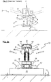
- a trolley 22 is movably mounted on such a mounting rail 10, as shown in FIG Figure 2b is shown.
- the trolley 22 has a chassis made up of an upper drive wheel 23 and lateral guide wheels 24 which are articulated to a suspension which engages around the support rail 10 from above.
- the trolley 22 has a current collector 25, which in Figure 2b the right-hand busbar 18 contacted.
- the transport trolley 22 can have an accumulator, a capacitor and / or an induction system as a power supply. Combinations are also provided in a production system, for example a power supply from an accumulator or capacitor in potentially explosive areas or moving rail sections, whereby the accumulator / capacitor can be charged in other rail sections by induction and / or sliding contacts.
- the transport carriage 22 is connected to a workpiece holder 26, which carries a workpiece of whatever configuration, for example a body. Such a transport carriage 22 can be moved in both directions and with any orientation on the support rail 20.
- FIGs 2c and 2d show, by way of example, the transport of a body 27 as a workpiece in a route section that is on both sides of the support rail 10 Has busbars 18.
- the transport takes place into the sheet level ( Figure 2c ) and from the plane of the sheet ( Fig. 2d ).
- the Fig. 3a the arrangement of the support rail 10 in a channel 28 (or driving space) which is delimited at the top by a pivotable cover 29.
- the pivotable cover 29 can be walked on by a person 30 in the closed state and has a lamellar profile 31 in the center through which a support arm 32 of the transport trolley 22 extends ( Figure 3b ).
- the slats of the slat profiles 31 are raised or lowered, so that the gap between the individual elements of the cover 29 is closed when no support arm 32 reaches through the cover 29.
- Fig. 3c i.e. show the course of the conveyor system through a drying chamber 33 with a body 27 arranged on the transport carriage 22. Comparatively high temperatures prevail in the drying chamber 33, which would hinder the undisturbed functioning of the conveyor system.
- a cooling duct 34 with a right-hand cooling air inlet 35 and a left-hand outlet 36 is provided in order to cool the conveyor system in channel 28 sufficiently.
- An alternative embodiment with cooling of the entire channel 28 is shown Fig. 3d .
- cold air also flows into the drying chamber 33 along the arrows 37, which can be advantageous for some applications.
- Figure 3e shows the conveyor system within an application in which work on the body 27 is carried out by robots 38.
- the detail section ( Fig. 3f ) shows an embodiment of the conveyor system in which the drive wheel 23 of the transport trolley 22 has an additional chain wheel 39 which engages in a profile 40 (or meshes with a profile 40) formed on the left side of the drive running surface 15.
- the profile 40 can be designed as a chain or as a rack.
- the form-fitting propulsion is preferably used when the adhesion of the drive wheel 23 on the drive running surface 15 is so low that the drive wheel 23 threatens to spin and thus propulsion losses would arise.
- Figure 4a shows an exemplary production system 50 with several processes that are connected by a conveyor system of the type according to the invention with a support rail of the type according to the invention.
- a workpiece can travel on different paths through this production plant and be at least partially treated in different processes.
- An exemplary run through the production system 50 is also described below with reference to FIG Figures 4b-d each showing the processes in an enlarged view.
- a workpiece 52 is first transferred to the production system 50 at A from the shell, for which a suitable transfer 51 is arranged ( Figure 4a , b ).
- a suitable transfer 51 is arranged ( Figure 4a , b ).
- an empty transport carriage 22 coming from a turning loop 53 is equipped with a workpiece 52, which is transported further in the direction of arrow B.
- the workpiece 52 is transferred to a further transport device, which guides the workpiece 52 through a bath 55 for cathodic dip painting (KTL).
- KTL cathodic dip painting
- a transfer 51 is arranged, which transfers the workpiece 52 to a transport trolley 22 for treatment of the workpiece 52 in a KTL dryer 56 ( Figure 4a , c ).
- the KTL dryer 56 has two dryer chambers 561, 562 through which the workpiece 52 can optionally pass.
- Gates 54 are arranged in front of and behind the KTL dryer 56.
- a buffer area 57 is connected downstream of the KTL dryer 56 ( Figure 4a , c ), in which the workpieces 52 are temporarily stored. Three buffer sections 571, 572, 573 are provided.
- a turntable 58 which optionally feeds a workpiece to a turning loop 53, is connected upstream of the buffer areas 571, 572. As the support rail 10 can be driven in both directions and in any orientation of the trolley 22, the path between the turntables 58 and the turning loop 53 can be traveled in both directions and the turntables 58 do not have to perform idle rotations in order to accommodate a trolley 22 with a rotated orientation.
- the buffer area 573 can be driven on in both directions and accepts workpieces 52 from the KTL dryer 56 as well as from a quality control, which will be discussed below.
- the workpieces 52 are fed to an application 59 via appropriately arranged switches 54 ( Figure 4a , d ), in which different work can be performed on the workpieces 52 under robot control, if necessary.
- a drag area 60 is shown in the application 59, in which the support rail 10 has a profile so that a chain wheel with a positive engagement in the profile ensures positive propulsion.
- the workpieces 52 can optionally be fed to a control area 61 or to a further process after the application 59.
- the control area 60 ( Figure 4a , e ) is connected back to the buffer area 573, so that workpieces 52 temporarily sorted out can be fed back to the application 59.
- the further process is, for example, a further dryer 62 with two dryer areas 621, 622 ( Figure 4a , d ).
- the transfer of the workpiece 2 to the respective dryer area 621, 622 takes place in the present case via a transverse shuttle 63.
- the dryer 62 is followed by a final assembly 64 ( Figure 4a , b ), with a swivel table 65 being arranged between the dryer 62 and the final assembly 64.
- the workpiece 52 is delivered to the dispatch department 68, with which the production is ended.
- the empty transport trolley 22 travels either to the first transfer 51 at A or to the transfer 51 in front of the KTL dryer 56, depending on which empty transport trolleys 22 are required at which point in production.
- the section between the final assembly 64 and the KTL dryer 56 passes under the KTL bath 55, for which purpose a slope 66 and a subsequent slope 67 are arranged. Both can, if necessary, also be implemented with the conveyor system according to the invention via a drag area.
- the process section is off Figure 4b in Figure 4d shown as it is designed according to the prior art.
- a workpiece 52 is transferred to the production plant, in which an empty transport carriage 6 is loaded with the workpiece 52. From there the trolley 6 travels to a transfer 51, where the transfer to another conveyor system takes place.
- the return path to the workpiece holder at A 'then takes place along a separate support rail 1 because it is not possible to drive on the support rail 1 in both directions if the transport carriage 6 is oriented in the opposite direction.
- a significantly longer transport route must therefore be installed for the connection, which requires a lot of space and which creates additional maintenance requirements.
- two support rails are also disadvantageously required for the connection between the dispatch 68 and the transfers 51 (at A 'or in front of the KTL dryer 56).
Abstract
Eine 1-spurige Förderanlage, insbesondere eine 1-spurige Elektrobodenbahn, mit einer Tragschiene (10), die eine obere Antriebslauffläche (15) und mindestens eine links- und eine rechtsseitige Ablauffläche (16) besitzt und einem auf der Tragschiene (10) verfahrbaren Transportwagen (22) mit einem Fahrwerk aus mindestens einem Antriebsrad (23), das auf der Antriebslauffläche (15) der Tragschiene (10) abrollt, und seitlichen Führungsrädern (24), die auf den links- und rechtsseitigen Ablaufflächen (16) der Tragschiene (10) abrollen, wobei die Tragschiene (10) an der der Antriebslauffläche (15) gegenüberliegenden Seite eine mittelbare oder unmittelbare Bodenbefestigung aufweist, sodass der Transportwagen (22) auf der Tragschiene (10) in beide Richtungen und um 180° gedreht verfahrbar ist.A 1-lane conveyor system, in particular a 1-lane electric floor conveyor, with a support rail (10) which has an upper drive running surface (15) and at least one left and right drainage surface (16) and a transport carriage that can be moved on the support rail (10) (22) with a chassis consisting of at least one drive wheel (23), which rolls on the drive running surface (15) of the support rail (10), and lateral guide wheels (24), which run on the left and right run-off surfaces (16) of the support rail (10) ), the support rail (10) having an indirect or direct floor attachment on the side opposite the drive running surface (15), so that the transport carriage (22) can be moved on the support rail (10) in both directions and rotated by 180 °.
Description
Die vorliegende Erfindung betrifft eine 1-spurige Förderanlage, insbesondere eine 1-spurige Elektrobodenbahn, mit einer Tragschiene, die eine obere Antriebslauffläche und mindestens eine links- und eine rechtsseitige Ablauffläche besitzt und einem auf der Tragschiene verfahrbaren Transportwagen mit einem Fahrwerk aus mindestens einem Antriebsrad, das auf der Antriebslauffläche der Tragschiene abrollt, und seitlichen Führungsrädern, die auf den links- und rechtsseitigen Ablaufflächen der Tragschiene abrollen.The present invention relates to a 1-lane conveyor system, in particular a 1-lane electric floor conveyor, with a support rail that has an upper drive running surface and at least one left and right run-off surface and a transport carriage that can be moved on the support rail and has a chassis made of at least one drive wheel, that rolls on the drive running surface of the support rail, and lateral guide wheels that roll on the left and right run-off surfaces of the support rail.
Außerdem betrifft die Erfindung eine Tragschiene für eine 1-spurige Förderanlage, insbesondere eine 1-spurige Elektrobodenbahn, mit einer oberen Antriebslauffläche und mindestens einer links- und einer rechtsseitigen Ablauffläche.The invention also relates to a support rail for a 1-lane conveyor system, in particular a 1-lane electric floor conveyor, with an upper drive running surface and at least one drainage surface on the left and one on the right.
Schließlich betrifft die Erfindung eine Produktionsanlage mit einer 1-spurigen Förderanlage, insbesondere einer 1-spurigen Elektrobodenbahn.Finally, the invention relates to a production system with a 1-lane conveyor system, in particular a 1-lane electric floor conveyor.
Förderanlagen und Tragschiene der eingangs genannten Art sind nach dem Stand der Technik bekannt und in unterschiedlichen Produktionsanlagen installiert, wie beispielsweise in Produktionsanlagen der Automobilindustrie. Um beispielsweise eine Karosserie als Werkstück durch eine Produktionsanlage zu führen, in der unterschiedliche Prozesse durchlaufen werden, ist die Karosserie auf dem Transportwagen angeordnet, der angetrieben auf der Tragschiene der Förderanlage verfahrbar ist. Auf einem solchen Transportwagen können die Karosserien vorgegebenen Pfaden der Produktionsanlagen folgen und in vorgegebener Reihenfolge unterschiedliche Prozesse durchlaufen.Conveyor systems and support rails of the type mentioned at the beginning are known from the prior art and are installed in different production systems, for example in production systems in the automotive industry. For example, in order to guide a body as a workpiece through a production system in which different processes are carried out, the body is arranged on the transport carriage, which can be driven on the carrier rail of the conveyor system. On such a transport trolley, the bodies can follow predetermined paths in the production facilities and run through different processes in a predetermined order.
Bestimmte Abschnitte einer solchen Produktionsanlage werden von dem Transportwagen in beiden Richtungen befahren. Aufgrund der seitlichen Fahrwerksaufhängung und der seitlichen Befestigung der Tragschiene wird jedoch eine Drehung des Transportwagens um 180° während eines Prozesses verhindert, weil sich die Aufhängung und die Befestigung in einem solchen Fall beim Weiterverfahren blockieren. Bei Prozessen mit einer 180° Drehung des Transportwagens erfolgt daher stets eine zusätzliche 180° Drehung mittels einer Drehstation, was nicht nur die Taktzeit erhöht, sondern auch eine weitere Drehstation erfordert. Alternativ ist nach dem Stand der Technik vorgesehen, dass der Transportwagen rückwärts auf den Tragschienen fahren kann, was konstruktionsbedingt nur mit einer vergleichsweise geringen Geschwindigkeit möglich ist.Certain sections of such a production facility are driven in both directions by the trolley. Due to the lateral suspension of the chassis and the lateral fastening of the support rail, however, a rotation of the transport trolley through 180 ° is prevented during a process, because the suspension and the fastening block each other in such a case as the process continues. In processes with a 180 ° rotation of the transport carriage, there is always an additional 180 ° rotation by means of a turning station, which not only increases the cycle time, but also requires a further turning station. Alternatively, the state of the art provides that the transport trolley can travel backwards on the support rails, which is only possible at a comparatively low speed due to the design.
Hiervon ausgehend ist es die Aufgabe der vorliegenden Erfindung, eine 1-spurige Förderanlage, eine Tragschiene für eine 1-spurige Förderanlage und/oder eine Produktionsanlage anzugeben, die die Nachteile des Standes der Technik zumindest teilweise behebt und insbesondere die Taktzeit der Produktionsanlage sowie den apparativen Aufwand reduziert.Based on this, the object of the present invention is to provide a 1-lane conveyor system, a support rail for a 1-lane conveyor system and / or a production system that at least partially eliminates the disadvantages of the prior art and in particular the cycle time of the production system and the apparatus Reduced effort.
Zunächst wird diese Aufgabe durch die 1-spurige Förderanlage nach Anspruch 1 gelöst. Erfindungsgemäß ist vorgesehen, dass die Tragschiene an der der Antriebslauffläche gegenüberliegenden Seite eine mittelbare oder unmittelbare Bodenbefestigung aufweist, sodass der Transportwagen auf der Tragschiene in beide Richtungen und um 180° gedreht verfahrbar ist.First of all, this object is achieved by the 1-lane conveyor system according to
Ferner wird die Aufgabe durch die Tragschiene nach Anspruch 9 gelöst, wonach vorgesehen ist, dass an der der Antriebsfläche gegenüberliegenden Seite eine mittelbare oder unmittelbare Bodenbefestigung angeordnet ist, sodass der Transportwagen in beide Richtungen und um 180° gedreht auf der Tragschiene verfahrbar ist.Furthermore, the object is achieved by the support rail according to
Schließlich wird die Aufgabe durch die Produktionsanlage nach Anspruch 16 gelöst, die mindestens zwei der Teilbereiche Beladebereich, Entladebereich, Umsetzbereich, Pufferbereich, Bearbeitungs- oder Behandlungsbereich, Kontrollbereich, Reparaturbereich und/oder Wartungsbereich umfasst.Finally, the object is achieved by the production plant according to
Die erfindungsgemäße Tragschiene zeichnet sich damit gegenüber den nach dem Stand der Technik bekannten Tragschienen durch eine Befestigung am waagerechten Bereich der kurzen Querschnittsseite, wodurch eine Befahrung der Tragschiene mit einem Transportwagen in beide Richtungen und mit beliebiger Orientierung des Transportwagens möglich ist, also auch nach einer Änderung der Orientierung und mithin einer 180° Drehung des Transportwagens. Hierdurch ist eine weitere 180° Drehung im Falle einer prozessbedingten Drehung des Transportwagens entbehrlich, was den apparativen Aufbau sowie die Taktzeit reduziert. Auch für Schnellverbindungen zwischen Prozessen ist die erfindungsgemäße Vorrichtung vorteilbehaftet, weil die Verbindungsabschnitte in beide Richtungen und in beliebiger Orientierung durch die Transportwagen befahrbar sind.The support rail according to the invention is thus distinguished from the support rails known from the prior art by being fastened to the horizontal area of the short cross-sectional side, which allows a transport carriage to drive on the support rail in both directions and with any orientation of the transport carriage, i.e. even after a change the orientation and therefore a 180 ° rotation of the trolley. As a result, a further 180 ° rotation in the case of a process-related rotation of the transport carriage is unnecessary, which reduces the apparatus structure and the cycle time. The device according to the invention is also advantageous for quick connections between processes because the connecting sections can be driven over by the transport trolleys in both directions and in any orientation.
Bevorzugte Ausführungsformen der Erfindung werden nachfolgend und in den Unteransprüchen beschrieben.Preferred embodiments of the invention are described below and in the subclaims.
Nach einer ersten bevorzugten Ausführungsform ist zur Bodenbefestigung der Tragschiene eine Schienenklemmung vorgesehen, indem vorzugsweise beidseitig der Tragschiene Klemmelemente angeordnet sind, die einerseits jeweils in eine Nut der Tragschiene eingreifen und andererseits unmittelbar mit dem Boden oder einem Träger lösbar befestigt sind, wobei die mindestens eine Nut vorzugsweise unterhalb der Ablauffläche angeordnet ist. Eine solche Klemmung benötigt für eine hinreichende Stabilität maximal 10 % der Tragschienenhöhe, was die Bauhöhe der Anlage in zulässigen Grenzen hält.According to a first preferred embodiment, a rail clamp is provided for fastening the carrier rail to the floor, in that clamping elements are preferably arranged on both sides of the carrier rail, which on the one hand each engage in a groove in the carrier rail and on the other hand are releasably fastened directly to the floor or a carrier, the at least one groove is preferably arranged below the drainage surface. Such a clamping requires a maximum of 10% of the mounting rail height for adequate stability, which keeps the overall height of the system within permissible limits.
Die erfindungsgemäße Befestigung der Tragschiene an der kurzen Querschnittseite ermöglicht zumindest abschnittsweise die bevorzugte Anordnung einer links- und einer rechtsseitigen Stromschiene, die mit mindestens einem Stromabnehmer des Transportwagens kontaktierbar sind. Hierdurch können die Transportwagen mit nur einem einzigen Stromabnehmer auf der Tragschiene in beide Richtungen und um 180° gedreht fahren.The fastening of the support rail according to the invention on the short cross-sectional side enables, at least in sections, the preferred arrangement of a left-hand and a right-hand busbar which can be contacted with at least one current collector of the transport vehicle. This allows the trolleys to travel in both directions and rotated by 180 ° with just a single current collector on the mounting rail.
Vorzugsweise sind links- und rechtsseitig der Tragschiene jeweils zwei vertikal voneinander beabstandete Ablaufflächen angeordnet, zwischen denen die Stromschienen verlaufen. Dabei ist die Bodenbefestigung der Tragschiene, insbesondere die Nuten zur Aufnahme der Klemmelemente, vorzugsweise unterhalb aller Ablaufflächen angeordnet, so dass der Transportwagen mit einer links- und rechtsseitigen Aufhängung der seitlichen Führungsräder frei auf der Tragschiene verfahrbar ist. Je weiter die Ablaufflächen in vertikaler Richtung voneinander beabstandet sind, desto stabiler ist der Transportwagen gegen Drehmomente um seine Längsachse gelagert, so dass ein in Abhängigkeit der Tragschienenhöhe größtmöglicher Abstand vorteilhaft ist.Preferably, two vertically spaced run-off surfaces are arranged on the left and right sides of the support rail, between which the busbars run. The base mounting of the support rail, in particular the grooves for receiving the clamping elements, is preferably arranged below all drainage surfaces, so that the trolley can be moved freely on the support rail with left and right-hand suspension of the lateral guide wheels. The further the run-off surfaces are spaced from one another in the vertical direction, the more stable the transport trolley is mounted against torques about its longitudinal axis, so that the greatest possible distance is advantageous depending on the height of the support rail.
Die Tragschiene ist vorzugsweise symmetrisch und im Wesentlichen als I-förmiges Aluminiumstrangpressprofil ausgebildet, wobei die seitlichen Ablaufflächen an den Außenflächen der horizontalen Abschnitte ausgebildet sind. Hierzwischen ist eine Verjüngung des Profils ausgebildet, wobei die bereits angesprochenen Stromschienen dem verjüngten Bereich der Tragschiene links- und rechtsseitig folgen. Damit die Stromschienen in Prozessen, bei denen die Werkstücke mit flüssigen Medien behandelt werden, beispielsweise in einer Lackieranlage, nicht beschmutzt werden, ragen die oberen Ablaufflächen seitlich derart über den verjüngten Bereich der Tragschiene hinaus, dass die Ablaufflächen als Tropfkanten ausgebildet sind. Abtropfende Medien gelangen somit nicht auf die Stromschienen und es ist ein störungsfreier Kontakt zwischen der Stromschiene und einem Stromabnehmer des Transportfahrzeugs gewährleistet.The support rail is preferably designed symmetrically and essentially as an I-shaped extruded aluminum profile, the lateral run-off surfaces being formed on the outer surfaces of the horizontal sections. In between, a tapering of the profile is formed, with the already mentioned busbars following the tapered area of the mounting rail on the left and right. So that the busbars are not soiled in processes in which the workpieces are treated with liquid media, for example in a paint shop, the upper run-off surfaces protrude laterally beyond the tapered area of the support rail in such a way that the run-off surfaces are designed as drip edges. Dripping media therefore do not get onto the busbars and trouble-free contact between the busbar and a current collector of the transport vehicle is guaranteed.
Die Förderanlage und mithin die Tragschiene kann nicht nur gerade und eben verlaufen, sondern es können auch horizontale und vertikale Kurven vorhanden sein. Insbesondere im Falle von Steigungen innerhalb oder außerhalb eines Prozesses oder im Fall einer verschmutzen Antriebslauffläche ist in der Praxis zu beobachten, dass das Antriebsrad durchdrehen kann, was zu Vortriebsverlusten und zu einem fehlerhaften Transport des Werkstücks durch den Prozess führt. Der Antriebsverlust kann auch dadurch bedingt sein, dass das Werkstück zur Stabilisierung im Prozess auf separaten Gleitflächen abgestützt wird, wodurch das Antriebsrad entlastet wird. Um dennoch für einen gleichmäßigen Vortrieb zu sorgen, ist nach einer besonders bevorzugten Ausführungsform der Erfindung vorgesehen, dass das Antriebsrad des Transportwagens koaxial und drehfest mit einem Kettenrad verbunden ist, dass formschlüssig in ein korrespondierendes Profil eingreift und einen formschlüssigen Vortrieb schafft. Das Profil ist vorzugsweise eine Kette oder eine Zahnstange, die links- und/oder rechtsseitig der Antriebslauffläche in einer Aufnahme der Tragschiene vorzugsweise formschlüssig gelagert ist. Eine Kette hat gegenüber einer Zahnstange den Vorteil, dass eine Kette auch bogenförmig in die vorgesehene Aufnahme gelegt werden kann und dort spannbar ist. Demgegenüber ist die Form einer Zahnstange dem Kurvenverlauf anzupassen und die Zahnstange ist dementsprechend anzufertigen. Die Höhenlage der Kette ist vorzugsweise so gewählt, dass der Wirkdurchmesser des Kettenrades dem Durchmesser des Antriebsrades entspricht. Damit bei einer Abnutzung des Antriebsrades und der damit verbundenen Durchmesserverkleinerung die Last nicht auf dem Kettenrad liegt, ist gegenüber dem Kettenrad am Antriebsrad eine harte Rolle, beispielsweise aus Stahl oder ähnlichem, angebracht, so dass die Position des Wirkdurchmessers zur Kette verschleißunabhängig konstant bleibt.The conveyor system and consequently the support rail can not only run straight and level, but horizontal and vertical curves can also be present. Particularly in the case of gradients inside or outside of a process or in the case of a dirty drive running surface, it can be observed in practice that the drive wheel can spin, which leads to propulsion losses and incorrect transport of the workpiece through the process. The drive loss can also be due to the fact that the workpiece is supported on separate sliding surfaces for stabilization in the process, whereby the drive wheel is relieved. In order to ensure even propulsion, a particularly preferred embodiment of the invention provides that the drive wheel of the trolley is coaxially and non-rotatably connected to a chain wheel that positively engages in a corresponding profile and creates a positive propulsion. The profile is preferably a chain or a toothed rack, which is mounted on the left and / or right side of the drive running surface in a receptacle on the support rail, preferably with a positive fit. A chain has the advantage over a toothed rack that a chain can also be laid in an arc in the intended receptacle and can be tensioned there. In contrast, the shape of a rack must be adapted to the curve and the rack must be manufactured accordingly. The height of the chain is preferably selected so that the effective diameter of the chain wheel corresponds to the diameter of the drive wheel. So that the load does not rest on the sprocket in the event of wear of the drive wheel and the associated reduction in diameter, a hard roller, for example made of steel or similar, is attached to the drive wheel opposite the chain wheel, so that the position of the effective diameter to the chain remains constant regardless of wear.
Die Förderanlage und mithin die Tragschiene verbindet nach einer bevorzugten Ausgestaltung der Erfindung zwei Produktionsbereiche einer Produktionsanlage, insbesondere als
- a) fest auf einer Bodenfläche montierte Fahrstrecke mit geraden und horizontal und/oder vertikal gekrümmten Abschnitten und/oder
- b) bewegte Tragschiene auf einer Vertikalumsetzeinrichtung und/oder
- c) bewegte Tragschiene auf einer Dreh- und Schwenkstation und/oder
- d) bewegte Tragschiene auf einer Horizontalumsetzeinrichtung und/oder
- e) bewegte Tragschiene in einer Fahrkursverzweigung (Weiche).
- a) track with straight and horizontally and / or vertically curved sections and / or fixedly mounted on a floor surface
- b) moving support rail on a vertical transfer device and / or
- c) moving support rail on a rotating and swiveling station and / or
- d) moving support rail on a horizontal transfer device and / or
- e) moving support rail in a course branch (switch).
Es wurde bereits angegeben, dass die Produktionsanlage mindestens zwei der Teilbereiche Beladebereich, Entladebereich, Umsetzbereich, Pufferbereich, Bearbeitungs- oder Behandlungsbereich, Kontrollbereich, Reparaturbereich und/oder Wartungsbereich umfasst. In einem Ladebereich und/oder einem Umsetzbereich können Werkstücke manuell oder automatisch auf Transportwagen oder auf damit verbundene Warenträger geladen oder von diesen Entladen werden.It has already been stated that the production system comprises at least two of the sub-areas loading area, unloading area, transfer area, buffer area, processing or treatment area, control area, repair area and / or maintenance area. In a loading area and / or a transfer area, workpieces can be loaded manually or automatically onto transport trolleys or onto goods carriers connected to them or unloaded from them.
Pufferbereiche dienen zur temporären Lagerung der Waren oder der Warenträger. Hierbei können die Waren oder der Warenträger auf dem Transportwagen verbleiben oder von diesen auf spezielle Lagerungselemente übergeben beziehungsweise von diesen übernommen werden.Buffer areas are used for the temporary storage of goods or the goods carriers. In this case, the goods or the goods carrier can remain on the transport trolley or be transferred to or taken over by special storage elements.
Bearbeitungs- oder Behandlungsbereiche sind beispielsweise:
- Fügebereiche, an denen Einzelteile gefügt werden (Rohbau),
- Oberflächenbehandlungsbereiche, wie beispielsweise Reinigungen oder eine Lackierung,
- Temperierbereiche, wie beispielsweise Öfen oder Kühlzonen,
- Montagebereiche für die Waren, beispielsweise Endmontage und/oder
- Kommissionierbereiche.
- Joining areas where individual parts are joined (shell construction),
- Surface treatment areas, such as cleaning or painting,
- Temperature control areas, such as ovens or cooling zones,
- Assembly areas for the goods, for example final assembly and / or
- Picking areas.
Alle genannten Bearbeitungen, Behandlungen, Kontrollen und/oder Reparaturen können dabei manuell und/oder maschinell erfolgen.All of the processing, treatments, controls and / or repairs mentioned can be carried out manually and / or by machine.
Konkrete Ausgestaltungen der vorliegenden Erfindung werden nachfolgend anhand der Figuren erläutert. Es zeigen:
- Fig. 1
- Querschnitt einer nach dem Stand der Technik bekannten Förderanlage,
- Fig. 2a, b
- Querschnitte einer Tragschiene und einer Förderanlage,
- Fig. 3a-f
- unterschiedliche Anwendungsbereiche einer Förderanlage,
- Fig. 4a-e
- eine Produktionsanlage mit unterschiedlichen Prozessen und
- Fig. 4f
- Ausschnitt einer Produktionsanlage (Stand der Technik).
- Fig. 1
- Cross-section of a conveyor system known from the prior art,
- Fig. 2a, b
- Cross-sections of a support rail and a conveyor system,
- Figures 3a-f
- different areas of application of a conveyor system,
- Figures 4a-e
- a production plant with different processes and
- Fig. 4f
- Section of a production plant (state of the art).
Die Tragschiene 10 besitzt ferner eine obere Antriebslauffläche 15 und pro Seite jeweils zwei vertikal voneinander beabstandete Ablaufflächen 16. Zwischen den Ablaufflächen 16 bildet das Profil eine Einschnürung 17, die beidseitig eine Führung für Stromschienen 18 bildet.The
Links- und rechtsseitig der Antriebslauffläche 15, sind Auflagen 19, 19' für formschlüssige Profile 20 ausgebildet, in die ein (in
Auf einer solchen Tragschiene 10 ist ein Transportwagen 22 verfahrbar gelagert, wie er in
Die
Die
- Eine von der für den Transportwagen schädliche Temperatur im Werkstückraum verschiedene Temperatur im Fahrraum des Transportwagens.
- Flexible Abdeckungen an Übergangsbereichen vom Werkstückraum zum Fahrraum.
- Beaufschlagung des Transportwagens mit einem Luftstrom mit unterschiedlicher Temperatur.
- Spülen des Fahrraums mit einem Luftstrom mit unterschiedlicher Temperatur.
- Temperierelemente am Fahrzeug oder an Fahrzeugkomponenten zur Erzeugung einer unschädlichen Temperatur.
- Thermisch isolierende Komponenten am Fahrzeug oder an Fahrraumabdeckungen.
- A temperature in the driving area of the transport cart that is different from the temperature in the workpiece space that is harmful to the transport cart.
- Flexible covers at the transition areas from the workpiece area to the driving area.
- Applying an air stream with different temperatures to the transport trolley.
- Rinsing the driving area with a stream of air at different temperatures.
- Temperature control elements on the vehicle or on vehicle components to generate a harmless temperature.
- Thermally insulating components on the vehicle or on driving area covers.
Zur Verringerung von ungünstigen Einflüssen durch Feuchtigkeit und Partikel sind folgende Maßnahmen vorgesehen:
- Flexible Abdeckungen an Übergangsbereichen vom Werkstückraum zum Fahrraum.
- Ein vom Werkstückraum verschiedener Luftdruck im Fahrraum.
- Gerichtete Luftströmung im Fahrraum.
- Formschlüssige Antriebskomponenten am Transportwagen und an der Schiene in gefährdeten Bereichen, beispielsweise durch eine Kette auf der Schiene und ein Zahnrad am Fahrzeug.
- Externe Antriebselemente zur Bewegung des Fahrzeugs in gefährdeten Bereichen, insbesondere Schleppförderer.
- Flexible covers at the transition areas from the workpiece area to the driving area.
- Air pressure in the driving area that differs from the workpiece area.
- Directed air flow in the driving area.
- Form-fitting drive components on the trolley and on the rail in hazardous areas, for example by a chain on the rail and a gear on the vehicle.
- External drive elements for moving the vehicle in endangered areas, especially drag conveyors.
Beispielhaft zeigt die
Die
Der Produktionsanlage 50 wird zunächst bei A vom Rohbau ein Werkstück 52 übergeben, wozu eine geeignete Übergabe 51 angeordnet ist (
Nach dem KTL-Tauchbad 55 ist eine Übergabe 51 angeordnet, die das Werkstück 52 einem Transportwagen 22 zur Behandlung des Werkstücks 52 in einem KTL-Trockner 56 übergibt (
Dem KTL-Trockner 56 ist ein Pufferbereich 57 nachgeschaltet (
Der Pufferbereich 573 ist in beide Richtungen befahrbar und übernimmt sowohl Werkstücke 52 aus dem KTL-Trockner 56 als auch aus einer Qualitätskontrolle, auf die nachfolgend noch eingegangen wird.The
Ausgehend vom Puffer 57 werden die Werkstücke 52 über entsprechend angeordnete Weichen 54 einer Applikation 59 zugeführt (
Der weitere Prozess ist beispielsweise ein weiterer Trockner 62 mit zwei Trocknerbereichen 621, 622 (
Dem Trockner 62 ist eine Endmontage 64 nachgeschaltet (
Insgesamt ergibt sich durch die beidseitige Befahrbarkeit der Tragschiene für eine solche Prozessanlage ein deutlich reduzierter apparativer Aufbau und Leerfahrten (beziehungsweise Leerdrehungen) können vermieden werden. Beispielsweise ist der Prozessabschnitt aus
Auch für die Verbindung zwischen dem Versand 68 und den Übergaben 51 (bei A' oder vor dem KTL-Trockner 56) sind nachteiligerweise nach dem Stand der Technik zwei Tragschienen erforderlich.
Claims (18)
dadurch gekennzeichnet, dass
die Tragschiene (10) an der der Antriebslauffläche (15) gegenüberliegenden Seite eine mittelbare oder unmittelbare Bodenbefestigung aufweist, sodass der Transportwagen (22) auf der Tragschiene (10) in beide Richtungen und um 180° gedreht verfahrbar ist.A 1-lane conveyor system, in particular a 1-lane electric floor conveyor, with a support rail (10) which has an upper drive running surface (15) and at least one left and right drainage surface (16) and a transport carriage that can be moved on the support rail (10) (22) with a chassis consisting of at least one drive wheel (23), which rolls on the drive running surface (15) of the support rail (10), and lateral guide wheels (24), which run on the left and right run-off surfaces (16) of the support rail (10) ) unroll,
characterized in that
the support rail (10) has an indirect or direct floor mounting on the side opposite the drive running surface (15) so that the transport carriage (22) can be moved on the support rail (10) in both directions and rotated by 180 °.
dadurch gekennzeichnet, dass
an der der Antriebslauffläche (15) gegenüberliegenden Seite eine mittelbare oder unmittelbare Bodenbefestigung angeordnet ist, sodass der Transportwagen (22) in beiden Richtungen und um 180° gedreht auf der Tragschiene (10) verfahrbar ist.Support rail for a 1-lane conveyor system, in particular a 1-lane electric floor conveyor, with an upper drive running surface (15) and at least one drainage surface (16) on the left and one on the right,
characterized in that
an indirect or direct floor mounting is arranged on the side opposite the drive running surface (15) so that the trolley (22) can be moved in both directions and rotated by 180 ° on the support rail (10).
Applications Claiming Priority (1)
| Application Number | Priority Date | Filing Date | Title |
|---|---|---|---|
| DE102018115485.2A DE102018115485A1 (en) | 2018-06-27 | 2018-06-27 | Conveyor system, mounting rail and production system |
Publications (2)
| Publication Number | Publication Date |
|---|---|
| EP3725654A1 true EP3725654A1 (en) | 2020-10-21 |
| EP3725654B1 EP3725654B1 (en) | 2022-10-12 |
Family
ID=66554269
Family Applications (1)
| Application Number | Title | Priority Date | Filing Date |
|---|---|---|---|
| EP19174645.2A Active EP3725654B1 (en) | 2018-06-27 | 2019-05-15 | Conveyor system |
Country Status (2)
| Country | Link |
|---|---|
| EP (1) | EP3725654B1 (en) |
| DE (1) | DE102018115485A1 (en) |
Citations (6)
| Publication number | Priority date | Publication date | Assignee | Title |
|---|---|---|---|---|
| DE2545907A1 (en) * | 1975-10-14 | 1977-04-21 | Demag Ag | Conveyor system rail mounted travelling crab - has freely rotating wheels with additional running surfaces on rail |
| WO2009000438A1 (en) * | 2007-06-26 | 2008-12-31 | Kuka Systems Gmbh | Conveying device for components, in particular vehicle bodies |
| WO2012031680A1 (en) * | 2010-09-10 | 2012-03-15 | Eisenmann Ag | Conveyor unit and conveyor system for conveying vehicle bodies and plant for machining vehicle bodies |
| DE102015003736A1 (en) | 2015-03-21 | 2016-09-22 | Eisenmann Se | Transport trolley and equipment for transporting objects |
| WO2017178317A1 (en) * | 2016-04-13 | 2017-10-19 | Eisenmann Se | Method and production system for producing vehicles, and surface treatment system for treating the surface of vehicle bodies |
| CN107963089A (en) * | 2017-11-27 | 2018-04-27 | 江苏高科物流科技股份有限公司 | One kind guidance vehicle driving system and automatic stereowarehouse |
Family Cites Families (2)
| Publication number | Priority date | Publication date | Assignee | Title |
|---|---|---|---|---|
| DE102016119540A1 (en) * | 2016-10-13 | 2018-04-19 | Eisenmann Se | Temperature control device, surface treatment plant, manufacturing plant and process for the production of products |
| DE102017118561A1 (en) * | 2017-08-15 | 2019-02-21 | Eisenmann Se | Conveying device for conveying workpieces in a surface treatment plant |
-
2018
- 2018-06-27 DE DE102018115485.2A patent/DE102018115485A1/en not_active Withdrawn
-
2019
- 2019-05-15 EP EP19174645.2A patent/EP3725654B1/en active Active
Patent Citations (6)
| Publication number | Priority date | Publication date | Assignee | Title |
|---|---|---|---|---|
| DE2545907A1 (en) * | 1975-10-14 | 1977-04-21 | Demag Ag | Conveyor system rail mounted travelling crab - has freely rotating wheels with additional running surfaces on rail |
| WO2009000438A1 (en) * | 2007-06-26 | 2008-12-31 | Kuka Systems Gmbh | Conveying device for components, in particular vehicle bodies |
| WO2012031680A1 (en) * | 2010-09-10 | 2012-03-15 | Eisenmann Ag | Conveyor unit and conveyor system for conveying vehicle bodies and plant for machining vehicle bodies |
| DE102015003736A1 (en) | 2015-03-21 | 2016-09-22 | Eisenmann Se | Transport trolley and equipment for transporting objects |
| WO2017178317A1 (en) * | 2016-04-13 | 2017-10-19 | Eisenmann Se | Method and production system for producing vehicles, and surface treatment system for treating the surface of vehicle bodies |
| CN107963089A (en) * | 2017-11-27 | 2018-04-27 | 江苏高科物流科技股份有限公司 | One kind guidance vehicle driving system and automatic stereowarehouse |
Also Published As
| Publication number | Publication date |
|---|---|
| EP3725654B1 (en) | 2022-10-12 |
| DE102018115485A1 (en) | 2020-01-02 |
Similar Documents
| Publication | Publication Date | Title |
|---|---|---|
| EP3442717B1 (en) | Method and production system for producing vehicles, and surface treatment system for treating the surface of vehicle bodies | |
| DE102015006098A1 (en) | Temperature control device for tempering workpieces | |
| DE102017012077B4 (en) | Transport system with self-propelled workpiece trolleys | |
| DE202013102199U1 (en) | Trailerzuganhänger | |
| CH639035A5 (en) | RAIL CONVEYOR. | |
| WO2016150543A1 (en) | Transport carriage and system for transporting objects | |
| EP3526534B1 (en) | Tempering apparatus, surface treatment plant, production plant and process for making products | |
| DE10063448A1 (en) | Installation for the treatment, in particular for painting, of objects, in particular vehicle bodies | |
| EP3481693A1 (en) | Transport system | |
| EP2847065A1 (en) | Processing system for construction units | |
| WO2003076315A1 (en) | System for treating, in particular, cataphoretically immersion painting vehicle bodies | |
| DE102009017982A1 (en) | Arrangement for use in assembly line to place workpieces at different machining positions in industry, has transport unit for transporting workpiece carrier and guiding carrier from one end to another end outside u-shaped guiding web | |
| EP3725654B1 (en) | Conveyor system | |
| DE10211214C1 (en) | Apparatus for cataphoretically dip coating a vehicle chassis comprises treating stations containing treating containers, and a conveying unit for guiding the chassis through the treating stations | |
| DE102017104751B4 (en) | transport device | |
| CH688146A5 (en) | Device for transporting at least one pot between a sliver-delivering spinning machine, for example, carding, and a sliver-fed spinning machine, such as distance. | |
| WO2016008552A1 (en) | Drive carriage for a transport device, and transport system | |
| DE4017261A1 (en) | SLIDING CARRIAGE FOR PAINT OR POWDER COATING SYSTEMS | |
| EP0654548B1 (en) | Apparatus for immersion painting | |
| WO1997017140A1 (en) | System for the surface treatment, in particular powder coating, of workpieces | |
| DE10324057B4 (en) | Arrangement for moving trolleys on connected congruent tracks | |
| EP0853143A1 (en) | Device for moving beams used in the transportation of objects | |
| DE2727938A1 (en) | Conveyor with roller track and transverse transporter - separates individual workpieces using truck and aligns with roller track | |
| DE102014110521B4 (en) | Processing system for building units and use of a processing system | |
| EP2707267A2 (en) | Spindle conveyor and plant for treating workpieces having such a spindle conveyor |
Legal Events
| Date | Code | Title | Description |
|---|---|---|---|
| PUAI | Public reference made under article 153(3) epc to a published international application that has entered the european phase |
Free format text: ORIGINAL CODE: 0009012 |
|
| STAA | Information on the status of an ep patent application or granted ep patent |
Free format text: STATUS: THE APPLICATION HAS BEEN PUBLISHED |
|
| AK | Designated contracting states |
Kind code of ref document: A1 Designated state(s): AL AT BE BG CH CY CZ DE DK EE ES FI FR GB GR HR HU IE IS IT LI LT LU LV MC MK MT NL NO PL PT RO RS SE SI SK SM TR |
|
| AX | Request for extension of the european patent |
Extension state: BA ME |
|
| STAA | Information on the status of an ep patent application or granted ep patent |
Free format text: STATUS: REQUEST FOR EXAMINATION WAS MADE |
|
| RAP1 | Party data changed (applicant data changed or rights of an application transferred) |
Owner name: PENTANOVA CS GMBH |
|
| 17P | Request for examination filed |
Effective date: 20201124 |
|
| RBV | Designated contracting states (corrected) |
Designated state(s): AL AT BE BG CH CY CZ DE DK EE ES FI FR GB GR HR HU IE IS IT LI LT LU LV MC MK MT NL NO PL PT RO RS SE SI SK SM TR |
|
| STAA | Information on the status of an ep patent application or granted ep patent |
Free format text: STATUS: EXAMINATION IS IN PROGRESS |
|
| 17Q | First examination report despatched |
Effective date: 20210422 |
|
| GRAP | Despatch of communication of intention to grant a patent |
Free format text: ORIGINAL CODE: EPIDOSNIGR1 |
|
| STAA | Information on the status of an ep patent application or granted ep patent |
Free format text: STATUS: GRANT OF PATENT IS INTENDED |
|
| RIC1 | Information provided on ipc code assigned before grant |
Ipc: B65G 49/04 20060101ALN20220621BHEP Ipc: B62D 65/18 20060101AFI20220621BHEP |
|
| INTG | Intention to grant announced |
Effective date: 20220708 |
|
| GRAS | Grant fee paid |
Free format text: ORIGINAL CODE: EPIDOSNIGR3 |
|
| GRAA | (expected) grant |
Free format text: ORIGINAL CODE: 0009210 |
|
| STAA | Information on the status of an ep patent application or granted ep patent |
Free format text: STATUS: THE PATENT HAS BEEN GRANTED |
|
| AK | Designated contracting states |
Kind code of ref document: B1 Designated state(s): AL AT BE BG CH CY CZ DE DK EE ES FI FR GB GR HR HU IE IS IT LI LT LU LV MC MK MT NL NO PL PT RO RS SE SI SK SM TR |
|
| REG | Reference to a national code |
Ref country code: GB Ref legal event code: FG4D Free format text: NOT ENGLISH |
|
| REG | Reference to a national code |
Ref country code: CH Ref legal event code: EP |
|
| REG | Reference to a national code |
Ref country code: DE Ref legal event code: R096 Ref document number: 502019005876 Country of ref document: DE |
|
| REG | Reference to a national code |
Ref country code: IE Ref legal event code: FG4D Free format text: LANGUAGE OF EP DOCUMENT: GERMAN |
|
| REG | Reference to a national code |
Ref country code: AT Ref legal event code: REF Ref document number: 1524018 Country of ref document: AT Kind code of ref document: T Effective date: 20221115 |
|
| REG | Reference to a national code |
Ref country code: LT Ref legal event code: MG9D |
|
| REG | Reference to a national code |
Ref country code: NL Ref legal event code: MP Effective date: 20221012 |
|
| PG25 | Lapsed in a contracting state [announced via postgrant information from national office to epo] |
Ref country code: NL Free format text: LAPSE BECAUSE OF FAILURE TO SUBMIT A TRANSLATION OF THE DESCRIPTION OR TO PAY THE FEE WITHIN THE PRESCRIBED TIME-LIMIT Effective date: 20221012 |
|
| PG25 | Lapsed in a contracting state [announced via postgrant information from national office to epo] |
Ref country code: SE Free format text: LAPSE BECAUSE OF FAILURE TO SUBMIT A TRANSLATION OF THE DESCRIPTION OR TO PAY THE FEE WITHIN THE PRESCRIBED TIME-LIMIT Effective date: 20221012 Ref country code: PT Free format text: LAPSE BECAUSE OF FAILURE TO SUBMIT A TRANSLATION OF THE DESCRIPTION OR TO PAY THE FEE WITHIN THE PRESCRIBED TIME-LIMIT Effective date: 20230213 Ref country code: NO Free format text: LAPSE BECAUSE OF FAILURE TO SUBMIT A TRANSLATION OF THE DESCRIPTION OR TO PAY THE FEE WITHIN THE PRESCRIBED TIME-LIMIT Effective date: 20230112 Ref country code: LT Free format text: LAPSE BECAUSE OF FAILURE TO SUBMIT A TRANSLATION OF THE DESCRIPTION OR TO PAY THE FEE WITHIN THE PRESCRIBED TIME-LIMIT Effective date: 20221012 Ref country code: FI Free format text: LAPSE BECAUSE OF FAILURE TO SUBMIT A TRANSLATION OF THE DESCRIPTION OR TO PAY THE FEE WITHIN THE PRESCRIBED TIME-LIMIT Effective date: 20221012 Ref country code: ES Free format text: LAPSE BECAUSE OF FAILURE TO SUBMIT A TRANSLATION OF THE DESCRIPTION OR TO PAY THE FEE WITHIN THE PRESCRIBED TIME-LIMIT Effective date: 20221012 |
|
| PG25 | Lapsed in a contracting state [announced via postgrant information from national office to epo] |
Ref country code: RS Free format text: LAPSE BECAUSE OF FAILURE TO SUBMIT A TRANSLATION OF THE DESCRIPTION OR TO PAY THE FEE WITHIN THE PRESCRIBED TIME-LIMIT Effective date: 20221012 Ref country code: PL Free format text: LAPSE BECAUSE OF FAILURE TO SUBMIT A TRANSLATION OF THE DESCRIPTION OR TO PAY THE FEE WITHIN THE PRESCRIBED TIME-LIMIT Effective date: 20221012 Ref country code: LV Free format text: LAPSE BECAUSE OF FAILURE TO SUBMIT A TRANSLATION OF THE DESCRIPTION OR TO PAY THE FEE WITHIN THE PRESCRIBED TIME-LIMIT Effective date: 20221012 Ref country code: IS Free format text: LAPSE BECAUSE OF FAILURE TO SUBMIT A TRANSLATION OF THE DESCRIPTION OR TO PAY THE FEE WITHIN THE PRESCRIBED TIME-LIMIT Effective date: 20230212 Ref country code: HR Free format text: LAPSE BECAUSE OF FAILURE TO SUBMIT A TRANSLATION OF THE DESCRIPTION OR TO PAY THE FEE WITHIN THE PRESCRIBED TIME-LIMIT Effective date: 20221012 Ref country code: GR Free format text: LAPSE BECAUSE OF FAILURE TO SUBMIT A TRANSLATION OF THE DESCRIPTION OR TO PAY THE FEE WITHIN THE PRESCRIBED TIME-LIMIT Effective date: 20230113 |
|
| REG | Reference to a national code |
Ref country code: DE Ref legal event code: R097 Ref document number: 502019005876 Country of ref document: DE |
|
| PG25 | Lapsed in a contracting state [announced via postgrant information from national office to epo] |
Ref country code: SM Free format text: LAPSE BECAUSE OF FAILURE TO SUBMIT A TRANSLATION OF THE DESCRIPTION OR TO PAY THE FEE WITHIN THE PRESCRIBED TIME-LIMIT Effective date: 20221012 Ref country code: RO Free format text: LAPSE BECAUSE OF FAILURE TO SUBMIT A TRANSLATION OF THE DESCRIPTION OR TO PAY THE FEE WITHIN THE PRESCRIBED TIME-LIMIT Effective date: 20221012 Ref country code: EE Free format text: LAPSE BECAUSE OF FAILURE TO SUBMIT A TRANSLATION OF THE DESCRIPTION OR TO PAY THE FEE WITHIN THE PRESCRIBED TIME-LIMIT Effective date: 20221012 Ref country code: DK Free format text: LAPSE BECAUSE OF FAILURE TO SUBMIT A TRANSLATION OF THE DESCRIPTION OR TO PAY THE FEE WITHIN THE PRESCRIBED TIME-LIMIT Effective date: 20221012 Ref country code: CZ Free format text: LAPSE BECAUSE OF FAILURE TO SUBMIT A TRANSLATION OF THE DESCRIPTION OR TO PAY THE FEE WITHIN THE PRESCRIBED TIME-LIMIT Effective date: 20221012 |
|
| PGFP | Annual fee paid to national office [announced via postgrant information from national office to epo] |
Ref country code: DE Payment date: 20230227 Year of fee payment: 5 |
|
| PLBE | No opposition filed within time limit |
Free format text: ORIGINAL CODE: 0009261 |
|
| STAA | Information on the status of an ep patent application or granted ep patent |
Free format text: STATUS: NO OPPOSITION FILED WITHIN TIME LIMIT |
|
| PG25 | Lapsed in a contracting state [announced via postgrant information from national office to epo] |
Ref country code: SK Free format text: LAPSE BECAUSE OF FAILURE TO SUBMIT A TRANSLATION OF THE DESCRIPTION OR TO PAY THE FEE WITHIN THE PRESCRIBED TIME-LIMIT Effective date: 20221012 Ref country code: AL Free format text: LAPSE BECAUSE OF FAILURE TO SUBMIT A TRANSLATION OF THE DESCRIPTION OR TO PAY THE FEE WITHIN THE PRESCRIBED TIME-LIMIT Effective date: 20221012 |
|
| 26N | No opposition filed |
Effective date: 20230713 |
|
| PG25 | Lapsed in a contracting state [announced via postgrant information from national office to epo] |
Ref country code: SI Free format text: LAPSE BECAUSE OF FAILURE TO SUBMIT A TRANSLATION OF THE DESCRIPTION OR TO PAY THE FEE WITHIN THE PRESCRIBED TIME-LIMIT Effective date: 20221012 |
|
| REG | Reference to a national code |
Ref country code: CH Ref legal event code: PL |
|
| PG25 | Lapsed in a contracting state [announced via postgrant information from national office to epo] |
Ref country code: MC Free format text: LAPSE BECAUSE OF FAILURE TO SUBMIT A TRANSLATION OF THE DESCRIPTION OR TO PAY THE FEE WITHIN THE PRESCRIBED TIME-LIMIT Effective date: 20221012 |
|
| GBPC | Gb: european patent ceased through non-payment of renewal fee |
Effective date: 20230515 |
|
| REG | Reference to a national code |
Ref country code: DE Ref legal event code: R082 Ref document number: 502019005876 Country of ref document: DE Representative=s name: RGTH PATENTANWAELTE PARTGMBB, DE Ref country code: DE Ref legal event code: R082 Ref document number: 502019005876 Country of ref document: DE Representative=s name: RGTH RICHTER GERBAULET THIELEMANN HOFMANN PATE, DE |
|
| REG | Reference to a national code |
Ref country code: BE Ref legal event code: MM Effective date: 20230531 |
|
| PG25 | Lapsed in a contracting state [announced via postgrant information from national office to epo] |
Ref country code: MC Free format text: LAPSE BECAUSE OF FAILURE TO SUBMIT A TRANSLATION OF THE DESCRIPTION OR TO PAY THE FEE WITHIN THE PRESCRIBED TIME-LIMIT Effective date: 20221012 Ref country code: LU Free format text: LAPSE BECAUSE OF NON-PAYMENT OF DUE FEES Effective date: 20230515 Ref country code: LI Free format text: LAPSE BECAUSE OF NON-PAYMENT OF DUE FEES Effective date: 20230531 Ref country code: CH Free format text: LAPSE BECAUSE OF NON-PAYMENT OF DUE FEES Effective date: 20230531 |
|
| REG | Reference to a national code |
Ref country code: IE Ref legal event code: MM4A |
|
| PG25 | Lapsed in a contracting state [announced via postgrant information from national office to epo] |
Ref country code: IE Free format text: LAPSE BECAUSE OF NON-PAYMENT OF DUE FEES Effective date: 20230515 |