EP3725583A1 - Battery-to-vehicle charging system - Google Patents
Battery-to-vehicle charging system Download PDFInfo
- Publication number
- EP3725583A1 EP3725583A1 EP19204235.6A EP19204235A EP3725583A1 EP 3725583 A1 EP3725583 A1 EP 3725583A1 EP 19204235 A EP19204235 A EP 19204235A EP 3725583 A1 EP3725583 A1 EP 3725583A1
- Authority
- EP
- European Patent Office
- Prior art keywords
- battery
- charge
- controller
- voltage
- power source
- Prior art date
- Legal status (The legal status is an assumption and is not a legal conclusion. Google has not performed a legal analysis and makes no representation as to the accuracy of the status listed.)
- Pending
Links
Images


Classifications
-
- B—PERFORMING OPERATIONS; TRANSPORTING
- B60—VEHICLES IN GENERAL
- B60L—PROPULSION OF ELECTRICALLY-PROPELLED VEHICLES; SUPPLYING ELECTRIC POWER FOR AUXILIARY EQUIPMENT OF ELECTRICALLY-PROPELLED VEHICLES; ELECTRODYNAMIC BRAKE SYSTEMS FOR VEHICLES IN GENERAL; MAGNETIC SUSPENSION OR LEVITATION FOR VEHICLES; MONITORING OPERATING VARIABLES OF ELECTRICALLY-PROPELLED VEHICLES; ELECTRIC SAFETY DEVICES FOR ELECTRICALLY-PROPELLED VEHICLES
- B60L53/00—Methods of charging batteries, specially adapted for electric vehicles; Charging stations or on-board charging equipment therefor; Exchange of energy storage elements in electric vehicles
- B60L53/10—Methods of charging batteries, specially adapted for electric vehicles; Charging stations or on-board charging equipment therefor; Exchange of energy storage elements in electric vehicles characterised by the energy transfer between the charging station and the vehicle
- B60L53/14—Conductive energy transfer
-
- B—PERFORMING OPERATIONS; TRANSPORTING
- B60—VEHICLES IN GENERAL
- B60L—PROPULSION OF ELECTRICALLY-PROPELLED VEHICLES; SUPPLYING ELECTRIC POWER FOR AUXILIARY EQUIPMENT OF ELECTRICALLY-PROPELLED VEHICLES; ELECTRODYNAMIC BRAKE SYSTEMS FOR VEHICLES IN GENERAL; MAGNETIC SUSPENSION OR LEVITATION FOR VEHICLES; MONITORING OPERATING VARIABLES OF ELECTRICALLY-PROPELLED VEHICLES; ELECTRIC SAFETY DEVICES FOR ELECTRICALLY-PROPELLED VEHICLES
- B60L53/00—Methods of charging batteries, specially adapted for electric vehicles; Charging stations or on-board charging equipment therefor; Exchange of energy storage elements in electric vehicles
- B60L53/10—Methods of charging batteries, specially adapted for electric vehicles; Charging stations or on-board charging equipment therefor; Exchange of energy storage elements in electric vehicles characterised by the energy transfer between the charging station and the vehicle
- B60L53/11—DC charging controlled by the charging station, e.g. mode 4
-
- B—PERFORMING OPERATIONS; TRANSPORTING
- B60—VEHICLES IN GENERAL
- B60L—PROPULSION OF ELECTRICALLY-PROPELLED VEHICLES; SUPPLYING ELECTRIC POWER FOR AUXILIARY EQUIPMENT OF ELECTRICALLY-PROPELLED VEHICLES; ELECTRODYNAMIC BRAKE SYSTEMS FOR VEHICLES IN GENERAL; MAGNETIC SUSPENSION OR LEVITATION FOR VEHICLES; MONITORING OPERATING VARIABLES OF ELECTRICALLY-PROPELLED VEHICLES; ELECTRIC SAFETY DEVICES FOR ELECTRICALLY-PROPELLED VEHICLES
- B60L53/00—Methods of charging batteries, specially adapted for electric vehicles; Charging stations or on-board charging equipment therefor; Exchange of energy storage elements in electric vehicles
- B60L53/10—Methods of charging batteries, specially adapted for electric vehicles; Charging stations or on-board charging equipment therefor; Exchange of energy storage elements in electric vehicles characterised by the energy transfer between the charging station and the vehicle
- B60L53/14—Conductive energy transfer
- B60L53/16—Connectors, e.g. plugs or sockets, specially adapted for charging electric vehicles
-
- B—PERFORMING OPERATIONS; TRANSPORTING
- B60—VEHICLES IN GENERAL
- B60L—PROPULSION OF ELECTRICALLY-PROPELLED VEHICLES; SUPPLYING ELECTRIC POWER FOR AUXILIARY EQUIPMENT OF ELECTRICALLY-PROPELLED VEHICLES; ELECTRODYNAMIC BRAKE SYSTEMS FOR VEHICLES IN GENERAL; MAGNETIC SUSPENSION OR LEVITATION FOR VEHICLES; MONITORING OPERATING VARIABLES OF ELECTRICALLY-PROPELLED VEHICLES; ELECTRIC SAFETY DEVICES FOR ELECTRICALLY-PROPELLED VEHICLES
- B60L53/00—Methods of charging batteries, specially adapted for electric vehicles; Charging stations or on-board charging equipment therefor; Exchange of energy storage elements in electric vehicles
- B60L53/20—Methods of charging batteries, specially adapted for electric vehicles; Charging stations or on-board charging equipment therefor; Exchange of energy storage elements in electric vehicles characterised by converters located in the vehicle
- B60L53/22—Constructional details or arrangements of charging converters specially adapted for charging electric vehicles
-
- B—PERFORMING OPERATIONS; TRANSPORTING
- B60—VEHICLES IN GENERAL
- B60L—PROPULSION OF ELECTRICALLY-PROPELLED VEHICLES; SUPPLYING ELECTRIC POWER FOR AUXILIARY EQUIPMENT OF ELECTRICALLY-PROPELLED VEHICLES; ELECTRODYNAMIC BRAKE SYSTEMS FOR VEHICLES IN GENERAL; MAGNETIC SUSPENSION OR LEVITATION FOR VEHICLES; MONITORING OPERATING VARIABLES OF ELECTRICALLY-PROPELLED VEHICLES; ELECTRIC SAFETY DEVICES FOR ELECTRICALLY-PROPELLED VEHICLES
- B60L53/00—Methods of charging batteries, specially adapted for electric vehicles; Charging stations or on-board charging equipment therefor; Exchange of energy storage elements in electric vehicles
- B60L53/20—Methods of charging batteries, specially adapted for electric vehicles; Charging stations or on-board charging equipment therefor; Exchange of energy storage elements in electric vehicles characterised by converters located in the vehicle
- B60L53/24—Using the vehicle's propulsion converter for charging
-
- B—PERFORMING OPERATIONS; TRANSPORTING
- B60—VEHICLES IN GENERAL
- B60L—PROPULSION OF ELECTRICALLY-PROPELLED VEHICLES; SUPPLYING ELECTRIC POWER FOR AUXILIARY EQUIPMENT OF ELECTRICALLY-PROPELLED VEHICLES; ELECTRODYNAMIC BRAKE SYSTEMS FOR VEHICLES IN GENERAL; MAGNETIC SUSPENSION OR LEVITATION FOR VEHICLES; MONITORING OPERATING VARIABLES OF ELECTRICALLY-PROPELLED VEHICLES; ELECTRIC SAFETY DEVICES FOR ELECTRICALLY-PROPELLED VEHICLES
- B60L53/00—Methods of charging batteries, specially adapted for electric vehicles; Charging stations or on-board charging equipment therefor; Exchange of energy storage elements in electric vehicles
- B60L53/30—Constructional details of charging stations
- B60L53/305—Communication interfaces
-
- B—PERFORMING OPERATIONS; TRANSPORTING
- B60—VEHICLES IN GENERAL
- B60L—PROPULSION OF ELECTRICALLY-PROPELLED VEHICLES; SUPPLYING ELECTRIC POWER FOR AUXILIARY EQUIPMENT OF ELECTRICALLY-PROPELLED VEHICLES; ELECTRODYNAMIC BRAKE SYSTEMS FOR VEHICLES IN GENERAL; MAGNETIC SUSPENSION OR LEVITATION FOR VEHICLES; MONITORING OPERATING VARIABLES OF ELECTRICALLY-PROPELLED VEHICLES; ELECTRIC SAFETY DEVICES FOR ELECTRICALLY-PROPELLED VEHICLES
- B60L53/00—Methods of charging batteries, specially adapted for electric vehicles; Charging stations or on-board charging equipment therefor; Exchange of energy storage elements in electric vehicles
- B60L53/50—Charging stations characterised by energy-storage or power-generation means
- B60L53/53—Batteries
-
- B—PERFORMING OPERATIONS; TRANSPORTING
- B60—VEHICLES IN GENERAL
- B60L—PROPULSION OF ELECTRICALLY-PROPELLED VEHICLES; SUPPLYING ELECTRIC POWER FOR AUXILIARY EQUIPMENT OF ELECTRICALLY-PROPELLED VEHICLES; ELECTRODYNAMIC BRAKE SYSTEMS FOR VEHICLES IN GENERAL; MAGNETIC SUSPENSION OR LEVITATION FOR VEHICLES; MONITORING OPERATING VARIABLES OF ELECTRICALLY-PROPELLED VEHICLES; ELECTRIC SAFETY DEVICES FOR ELECTRICALLY-PROPELLED VEHICLES
- B60L53/00—Methods of charging batteries, specially adapted for electric vehicles; Charging stations or on-board charging equipment therefor; Exchange of energy storage elements in electric vehicles
- B60L53/60—Monitoring or controlling charging stations
- B60L53/62—Monitoring or controlling charging stations in response to charging parameters, e.g. current, voltage or electrical charge
-
- B—PERFORMING OPERATIONS; TRANSPORTING
- B60—VEHICLES IN GENERAL
- B60L—PROPULSION OF ELECTRICALLY-PROPELLED VEHICLES; SUPPLYING ELECTRIC POWER FOR AUXILIARY EQUIPMENT OF ELECTRICALLY-PROPELLED VEHICLES; ELECTRODYNAMIC BRAKE SYSTEMS FOR VEHICLES IN GENERAL; MAGNETIC SUSPENSION OR LEVITATION FOR VEHICLES; MONITORING OPERATING VARIABLES OF ELECTRICALLY-PROPELLED VEHICLES; ELECTRIC SAFETY DEVICES FOR ELECTRICALLY-PROPELLED VEHICLES
- B60L53/00—Methods of charging batteries, specially adapted for electric vehicles; Charging stations or on-board charging equipment therefor; Exchange of energy storage elements in electric vehicles
- B60L53/60—Monitoring or controlling charging stations
- B60L53/66—Data transfer between charging stations and vehicles
-
- H—ELECTRICITY
- H02—GENERATION; CONVERSION OR DISTRIBUTION OF ELECTRIC POWER
- H02J—CIRCUIT ARRANGEMENTS OR SYSTEMS FOR SUPPLYING OR DISTRIBUTING ELECTRIC POWER; SYSTEMS FOR STORING ELECTRIC ENERGY
- H02J7/00—Circuit arrangements for charging or depolarising batteries or for supplying loads from batteries
- H02J7/00032—Circuit arrangements for charging or depolarising batteries or for supplying loads from batteries characterised by data exchange
- H02J7/00034—Charger exchanging data with an electronic device, i.e. telephone, whose internal battery is under charge
-
- H—ELECTRICITY
- H02—GENERATION; CONVERSION OR DISTRIBUTION OF ELECTRIC POWER
- H02J—CIRCUIT ARRANGEMENTS OR SYSTEMS FOR SUPPLYING OR DISTRIBUTING ELECTRIC POWER; SYSTEMS FOR STORING ELECTRIC ENERGY
- H02J7/00—Circuit arrangements for charging or depolarising batteries or for supplying loads from batteries
- H02J7/34—Parallel operation in networks using both storage and other dc sources, e.g. providing buffering
- H02J7/342—The other DC source being a battery actively interacting with the first one, i.e. battery to battery charging
-
- H—ELECTRICITY
- H02—GENERATION; CONVERSION OR DISTRIBUTION OF ELECTRIC POWER
- H02M—APPARATUS FOR CONVERSION BETWEEN AC AND AC, BETWEEN AC AND DC, OR BETWEEN DC AND DC, AND FOR USE WITH MAINS OR SIMILAR POWER SUPPLY SYSTEMS; CONVERSION OF DC OR AC INPUT POWER INTO SURGE OUTPUT POWER; CONTROL OR REGULATION THEREOF
- H02M1/00—Details of apparatus for conversion
- H02M1/42—Circuits or arrangements for compensating for or adjusting power factor in converters or inverters
- H02M1/4208—Arrangements for improving power factor of AC input
- H02M1/4225—Arrangements for improving power factor of AC input using a non-isolated boost converter
-
- B—PERFORMING OPERATIONS; TRANSPORTING
- B60—VEHICLES IN GENERAL
- B60L—PROPULSION OF ELECTRICALLY-PROPELLED VEHICLES; SUPPLYING ELECTRIC POWER FOR AUXILIARY EQUIPMENT OF ELECTRICALLY-PROPELLED VEHICLES; ELECTRODYNAMIC BRAKE SYSTEMS FOR VEHICLES IN GENERAL; MAGNETIC SUSPENSION OR LEVITATION FOR VEHICLES; MONITORING OPERATING VARIABLES OF ELECTRICALLY-PROPELLED VEHICLES; ELECTRIC SAFETY DEVICES FOR ELECTRICALLY-PROPELLED VEHICLES
- B60L2210/00—Converter types
- B60L2210/10—DC to DC converters
- B60L2210/14—Boost converters
-
- B—PERFORMING OPERATIONS; TRANSPORTING
- B60—VEHICLES IN GENERAL
- B60L—PROPULSION OF ELECTRICALLY-PROPELLED VEHICLES; SUPPLYING ELECTRIC POWER FOR AUXILIARY EQUIPMENT OF ELECTRICALLY-PROPELLED VEHICLES; ELECTRODYNAMIC BRAKE SYSTEMS FOR VEHICLES IN GENERAL; MAGNETIC SUSPENSION OR LEVITATION FOR VEHICLES; MONITORING OPERATING VARIABLES OF ELECTRICALLY-PROPELLED VEHICLES; ELECTRIC SAFETY DEVICES FOR ELECTRICALLY-PROPELLED VEHICLES
- B60L2210/00—Converter types
- B60L2210/20—AC to AC converters
-
- B—PERFORMING OPERATIONS; TRANSPORTING
- B60—VEHICLES IN GENERAL
- B60L—PROPULSION OF ELECTRICALLY-PROPELLED VEHICLES; SUPPLYING ELECTRIC POWER FOR AUXILIARY EQUIPMENT OF ELECTRICALLY-PROPELLED VEHICLES; ELECTRODYNAMIC BRAKE SYSTEMS FOR VEHICLES IN GENERAL; MAGNETIC SUSPENSION OR LEVITATION FOR VEHICLES; MONITORING OPERATING VARIABLES OF ELECTRICALLY-PROPELLED VEHICLES; ELECTRIC SAFETY DEVICES FOR ELECTRICALLY-PROPELLED VEHICLES
- B60L2210/00—Converter types
- B60L2210/30—AC to DC converters
-
- B—PERFORMING OPERATIONS; TRANSPORTING
- B60—VEHICLES IN GENERAL
- B60L—PROPULSION OF ELECTRICALLY-PROPELLED VEHICLES; SUPPLYING ELECTRIC POWER FOR AUXILIARY EQUIPMENT OF ELECTRICALLY-PROPELLED VEHICLES; ELECTRODYNAMIC BRAKE SYSTEMS FOR VEHICLES IN GENERAL; MAGNETIC SUSPENSION OR LEVITATION FOR VEHICLES; MONITORING OPERATING VARIABLES OF ELECTRICALLY-PROPELLED VEHICLES; ELECTRIC SAFETY DEVICES FOR ELECTRICALLY-PROPELLED VEHICLES
- B60L2240/00—Control parameters of input or output; Target parameters
- B60L2240/40—Drive Train control parameters
- B60L2240/54—Drive Train control parameters related to batteries
- B60L2240/547—Voltage
-
- B—PERFORMING OPERATIONS; TRANSPORTING
- B60—VEHICLES IN GENERAL
- B60Y—INDEXING SCHEME RELATING TO ASPECTS CROSS-CUTTING VEHICLE TECHNOLOGY
- B60Y2200/00—Type of vehicle
- B60Y2200/90—Vehicles comprising electric prime movers
- B60Y2200/91—Electric vehicles
-
- H—ELECTRICITY
- H02—GENERATION; CONVERSION OR DISTRIBUTION OF ELECTRIC POWER
- H02J—CIRCUIT ARRANGEMENTS OR SYSTEMS FOR SUPPLYING OR DISTRIBUTING ELECTRIC POWER; SYSTEMS FOR STORING ELECTRIC ENERGY
- H02J2207/00—Indexing scheme relating to details of circuit arrangements for charging or depolarising batteries or for supplying loads from batteries
- H02J2207/20—Charging or discharging characterised by the power electronics converter
-
- H—ELECTRICITY
- H02—GENERATION; CONVERSION OR DISTRIBUTION OF ELECTRIC POWER
- H02J—CIRCUIT ARRANGEMENTS OR SYSTEMS FOR SUPPLYING OR DISTRIBUTING ELECTRIC POWER; SYSTEMS FOR STORING ELECTRIC ENERGY
- H02J2207/00—Indexing scheme relating to details of circuit arrangements for charging or depolarising batteries or for supplying loads from batteries
- H02J2207/40—Indexing scheme relating to details of circuit arrangements for charging or depolarising batteries or for supplying loads from batteries adapted for charging from various sources, e.g. AC, DC or multivoltage
-
- H—ELECTRICITY
- H02—GENERATION; CONVERSION OR DISTRIBUTION OF ELECTRIC POWER
- H02J—CIRCUIT ARRANGEMENTS OR SYSTEMS FOR SUPPLYING OR DISTRIBUTING ELECTRIC POWER; SYSTEMS FOR STORING ELECTRIC ENERGY
- H02J2310/00—The network for supplying or distributing electric power characterised by its spatial reach or by the load
- H02J2310/40—The network being an on-board power network, i.e. within a vehicle
- H02J2310/48—The network being an on-board power network, i.e. within a vehicle for electric vehicles [EV] or hybrid vehicles [HEV]
-
- Y—GENERAL TAGGING OF NEW TECHNOLOGICAL DEVELOPMENTS; GENERAL TAGGING OF CROSS-SECTIONAL TECHNOLOGIES SPANNING OVER SEVERAL SECTIONS OF THE IPC; TECHNICAL SUBJECTS COVERED BY FORMER USPC CROSS-REFERENCE ART COLLECTIONS [XRACs] AND DIGESTS
- Y02—TECHNOLOGIES OR APPLICATIONS FOR MITIGATION OR ADAPTATION AGAINST CLIMATE CHANGE
- Y02B—CLIMATE CHANGE MITIGATION TECHNOLOGIES RELATED TO BUILDINGS, e.g. HOUSING, HOUSE APPLIANCES OR RELATED END-USER APPLICATIONS
- Y02B70/00—Technologies for an efficient end-user side electric power management and consumption
- Y02B70/10—Technologies improving the efficiency by using switched-mode power supplies [SMPS], i.e. efficient power electronics conversion e.g. power factor correction or reduction of losses in power supplies or efficient standby modes
-
- Y—GENERAL TAGGING OF NEW TECHNOLOGICAL DEVELOPMENTS; GENERAL TAGGING OF CROSS-SECTIONAL TECHNOLOGIES SPANNING OVER SEVERAL SECTIONS OF THE IPC; TECHNICAL SUBJECTS COVERED BY FORMER USPC CROSS-REFERENCE ART COLLECTIONS [XRACs] AND DIGESTS
- Y02—TECHNOLOGIES OR APPLICATIONS FOR MITIGATION OR ADAPTATION AGAINST CLIMATE CHANGE
- Y02T—CLIMATE CHANGE MITIGATION TECHNOLOGIES RELATED TO TRANSPORTATION
- Y02T10/00—Road transport of goods or passengers
- Y02T10/60—Other road transportation technologies with climate change mitigation effect
- Y02T10/70—Energy storage systems for electromobility, e.g. batteries
-
- Y—GENERAL TAGGING OF NEW TECHNOLOGICAL DEVELOPMENTS; GENERAL TAGGING OF CROSS-SECTIONAL TECHNOLOGIES SPANNING OVER SEVERAL SECTIONS OF THE IPC; TECHNICAL SUBJECTS COVERED BY FORMER USPC CROSS-REFERENCE ART COLLECTIONS [XRACs] AND DIGESTS
- Y02—TECHNOLOGIES OR APPLICATIONS FOR MITIGATION OR ADAPTATION AGAINST CLIMATE CHANGE
- Y02T—CLIMATE CHANGE MITIGATION TECHNOLOGIES RELATED TO TRANSPORTATION
- Y02T10/00—Road transport of goods or passengers
- Y02T10/60—Other road transportation technologies with climate change mitigation effect
- Y02T10/7072—Electromobility specific charging systems or methods for batteries, ultracapacitors, supercapacitors or double-layer capacitors
-
- Y—GENERAL TAGGING OF NEW TECHNOLOGICAL DEVELOPMENTS; GENERAL TAGGING OF CROSS-SECTIONAL TECHNOLOGIES SPANNING OVER SEVERAL SECTIONS OF THE IPC; TECHNICAL SUBJECTS COVERED BY FORMER USPC CROSS-REFERENCE ART COLLECTIONS [XRACs] AND DIGESTS
- Y02—TECHNOLOGIES OR APPLICATIONS FOR MITIGATION OR ADAPTATION AGAINST CLIMATE CHANGE
- Y02T—CLIMATE CHANGE MITIGATION TECHNOLOGIES RELATED TO TRANSPORTATION
- Y02T10/00—Road transport of goods or passengers
- Y02T10/60—Other road transportation technologies with climate change mitigation effect
- Y02T10/72—Electric energy management in electromobility
-
- Y—GENERAL TAGGING OF NEW TECHNOLOGICAL DEVELOPMENTS; GENERAL TAGGING OF CROSS-SECTIONAL TECHNOLOGIES SPANNING OVER SEVERAL SECTIONS OF THE IPC; TECHNICAL SUBJECTS COVERED BY FORMER USPC CROSS-REFERENCE ART COLLECTIONS [XRACs] AND DIGESTS
- Y02—TECHNOLOGIES OR APPLICATIONS FOR MITIGATION OR ADAPTATION AGAINST CLIMATE CHANGE
- Y02T—CLIMATE CHANGE MITIGATION TECHNOLOGIES RELATED TO TRANSPORTATION
- Y02T90/00—Enabling technologies or technologies with a potential or indirect contribution to GHG emissions mitigation
- Y02T90/10—Technologies relating to charging of electric vehicles
- Y02T90/12—Electric charging stations
-
- Y—GENERAL TAGGING OF NEW TECHNOLOGICAL DEVELOPMENTS; GENERAL TAGGING OF CROSS-SECTIONAL TECHNOLOGIES SPANNING OVER SEVERAL SECTIONS OF THE IPC; TECHNICAL SUBJECTS COVERED BY FORMER USPC CROSS-REFERENCE ART COLLECTIONS [XRACs] AND DIGESTS
- Y02—TECHNOLOGIES OR APPLICATIONS FOR MITIGATION OR ADAPTATION AGAINST CLIMATE CHANGE
- Y02T—CLIMATE CHANGE MITIGATION TECHNOLOGIES RELATED TO TRANSPORTATION
- Y02T90/00—Enabling technologies or technologies with a potential or indirect contribution to GHG emissions mitigation
- Y02T90/10—Technologies relating to charging of electric vehicles
- Y02T90/14—Plug-in electric vehicles
-
- Y—GENERAL TAGGING OF NEW TECHNOLOGICAL DEVELOPMENTS; GENERAL TAGGING OF CROSS-SECTIONAL TECHNOLOGIES SPANNING OVER SEVERAL SECTIONS OF THE IPC; TECHNICAL SUBJECTS COVERED BY FORMER USPC CROSS-REFERENCE ART COLLECTIONS [XRACs] AND DIGESTS
- Y02—TECHNOLOGIES OR APPLICATIONS FOR MITIGATION OR ADAPTATION AGAINST CLIMATE CHANGE
- Y02T—CLIMATE CHANGE MITIGATION TECHNOLOGIES RELATED TO TRANSPORTATION
- Y02T90/00—Enabling technologies or technologies with a potential or indirect contribution to GHG emissions mitigation
- Y02T90/10—Technologies relating to charging of electric vehicles
- Y02T90/16—Information or communication technologies improving the operation of electric vehicles
Definitions
- the present disclosure relate to a battery-to-vehicle charging system and, more particularly, a battery-to-vehicle charging system that can charge a battery in a vehicle by supplying DC power to the vehicle from a battery of an external charging device even though there is no separate power conversion device in the external charging device.
- a mobile charging system is a system for users of electric vehicles to more conveniently solve a problem of an insufficient battery level and charge batteries.
- a mobile charging system includes a battery that is an energy storage device for storing electrical energy and a power conversion device that converts the energy stored in the battery into the rate required by vehicles.
- Such a mobile charging system of the related art includes not only a battery for storing electrical energy, but a power conversion device having large volume and weight, the entire size and weight are large. Accordingly, there is a problem that the convenience for mobility or portability is low, so the mobile charging system can be operated only in the type of an exclusive charging service vehicle.
- An aspect of the present disclosure is to provide a battery-to-vehicle charging system that can charge a battery in a vehicle by providing AC power directly supplied from a battery of an external charging device without a separate power conversion device to the battery in the vehicle.
- a battery-to-vehicle charging system includes: a vehicle including an on-board charger including a boost converter circuit, a first battery that is charged with a charge voltage output from the on-board charger, and a first controller controlling a charge process on the basis of a type of a charge power source provided from outside; and an energy storage device including a second battery storing DC charge power provided to the first battery, and a second controller providing a determination signal for the type of the charge power source to the first controller, in which when the first controller receives the determination signal from the second controller and the charge power source is determined as the energy storage device, the first controller controls the boost converter circuit to operate.
- the energy storage device may not include a power conversion device for converting voltage of the second battery into voltage having magnitude that can charge the first battery.
- the first controller may apply charge power, which is provided from the energy storage device, to an input terminal of the boost converter circuit.
- the first controller when the first controller receives the determination signal in power line communication through a control pilot line from the second controller and the charge power source is determined as the energy storage device, the first controller may apply charge power, which is provided from the energy storage device, to an input terminal of the boost converter circuit.
- the boost converter circuit may have a boost converter topology including an inductor, a diode, and a switching device, and when the first controller determines the charge power source as the energy storage device, a duty of the switching device may be determined on the basis of a ratio of voltage of the second battery and target voltage of an output terminal of the boost converter circuit.
- the on-board charger may further include a DC converter that converts magnitude of output voltage of the boost converter circuit into predetermined magnitude of the charge voltage.
- a battery-to-vehicle charging system includes: a charging inlet having a plurality of terminals to which a connect of an external charge power source is coupled, to which charge power is applied from the connector, and to which a control signal for charging is provided; an on-board charger including a power factor correction circuit that has an input terminal connected to an AC power input terminal of the charging inlet and has a boot converter topology; a battery that is charged with a charge voltage output from the on-board charger; and a controller determining a type of the charge power on the basis of a control signal input from the external charge power source through a terminal of the charging inlet, and controlling a charge process on the basis of the determined type of the charge power source, in which the controller controls the power factor correction circuit to operate as a boost converter when the determined charge power source is determined as a charge power source that providing DC power of voltage lower than voltage of the battery to the AC power input terminal.
- the controller may determine the type of the charge power source on the basis of a control signal input through a control pilot line formed by coupling the connector to the charging inlet.
- the controller may receive a control signal in power line communication through a control pilot line formed by coupling the connector to the charging inlet.
- the controller may electrically connect the DC power input terminal to the battery without operating the on-board charger when the determined charge power source is determined as a charge power source that provides DC power higher than voltage of the battery to a DC power input terminal of the charging inlet.
- the power factor correction circuit may have a boost converter topology including an inductor, a diode, and a switching device, and the controller may determine a duty of the switching device on the basis of a ratio of voltage of the charge power source and target voltage of an output terminal of the power factor correction circuit when the determined charge power source is determined as a charge power source that provides DC power of voltage lower than voltage of the battery to the AC power input terminal.
- the power factor correction circuit may have a boost converter topology including an inductor, a diode, and a switching device, and the controller may determine a duty of the switching device by performing voltage control and current control such that voltage of the power factor correction circuit becomes target voltage when the determined charge power source is a charge power source that provides AC power to the AC power input terminal.
- the battery-to-vehicle charging system it is possible to charge a high-voltage battery in a vehicle from a low-voltage battery using a charging connector that has been used in the related art.
- a charging connector that has been used in the related art.
- the battery-to-vehicle charging system may be referred to as a B2V (Battery-to-Vehicle) charging system that is generally used as an abbreviation in this field.
- B2V Battery-to-Vehicle
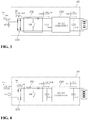
- FIG. 1 is a block diagram showing the configuration of a battery-to-vehicle charging system according to an exemplary embodiment of the present disclosure.
- a B2V charging system may include a vehicle 20 having a battery 25 that is the charge target, and an energy storage device 10 that is a type of mobile charging devices having another battery 11 storing energy for providing DC charge power to the battery 25 from the outside of the vehicle 20.
- the energy storage device 10 may include the battery 11 storing charge energy, a controller 13 for performing necessary control when the energy stored in the battery 11 is supplied to the vehicle, and a charging connector 15 that is coupled to a charging inlet 21 of the vehicle.
- the controller 13 of the energy storage device 10 may be a processor (e.g., computer, microprocessor, CPU, ASIC, circuitry, logic circuits etc.).
- the controller 13 may be implemented by a non-transitory memory storing, e.g., a program(s), software instructions reproducing algorithms, etc., which, when executed, controls operations of the energy storage device 10, and a processor configured to execute the program(s), software instructions reproducing algorithms, etc.
- the memory and the processor may be implemented as separate semiconductor circuits.
- the memory and the processor may be implemented as a single integrated semiconductor circuit.
- the processor may embody one or more processor(s).
- the energy storage device 10 which is a concept generally designate a fixed energy storage device and a mobile energy storage device, may be a device that supplies energy without having or using a separate power conversion device.
- the battery 11 may be a part that stores electrical energy for charging the battery 25 in a vehicle.
- the battery 11 included in the energy storage device 10 may have a limit in capacity of energy, which can be stored, and output voltage.
- batteries that output high voltage e.g., about 800V
- the battery 11 included in the energy storage device 10 has difficulty in outputting voltage as high as the voltage of the battery 25 in a vehicle.
- a power conversion circuit for increasing the voltage of the battery 11 is provided in an energy storage device and a method of supplying voltage to the battery 25 in a vehicle through a DC charge pin after increasing the voltage of the battery 25 has been used.
- an energy storage device since an energy storage device has a power conversion circuit for increasing voltage, there may be a problem for downsizing of the energy storage device and the price of the energy storage device may increase.
- Various exemplary embodiments of the present disclosure provide a technology that can charge a battery in a vehicle by providing the energy stored in a battery of an energy storage device to the battery in a vehicle which has higher voltage than the battery of the energy storage device without a power conversion circuit in the energy storage device.
- the controller 13 of the energy storage device 10 can provide a signal for recognizing a charge power source to the controller 27 in the vehicle 20 when the energy storage device 10 is connected to the vehicle 20 for charging.
- the controller 13 can provide a signal for confirming that a charge power source is the battery 11 to the controller 27 in the vehicle 20 using a Control Pilot (CP) signal.
- CP Control Pilot
- This CP signal may be provided through a CP pin of the charging connector 15 (e.g., the pin No. 4 of the charging connector 15) that is coupled to the charging inlet 21 of the vehicle.
- the charging connector 15 may be a part that provides a control signal for charging and charge power to the vehicle 20 by being coupled to the charging inlet 21 of the vehicle.
- the charging connector 15 may be a Society of Automotive Engineer (SAE) J1772 connector.
- SAE J1772 combo connector that can be used in common for AC charge power and DC charge power of SAE J1772 connectors. That is, SAE J1772 combo connector is a standard connector designed to be used in common in two charge modes of slow charging that provides AC power to a vehicle and quick charging that provides DC power to a vehicle.
- SAE J1772 combo connector includes an AC output pin (e.g., a pin No. 1 and a pin No. 2) for providing AC charge power in slow charging, a ground pin (e.g., a pin No. 3), a CP pin (e.g., a pin No. 4) to which a CP signal is provided, a Proximity Detection (PD) pin (e.g., a pin No. 5) for determining the connection state of the connector, and a DC plus (+) pin (e.g., a pin No. 6) and a DC minus (-) pin (e.g., a pin No. 7) for providing DC charge power in quick charging.
- DC charge power 7 for providing DC charge power can be used when the voltage of DC charge power provided to a vehicle from a charging facility or an energy storage device is voltage, which can charge the battery 25 that is the charge target, and the DC charge power can be directly applied to the battery 25 without an conversion process.
- the energy storage device 10 may be configured to transmit DC power of the battery 11 using the pins Nos. 1 and 2 of the charging connector 15, that is, the pins provided to usually provide AC power in slow charging.
- the energy storage device 10 two terminals (e.g., a plus terminal and minus terminal) of the battery 11 can be directly connected to the pins Nos. 1 and 2 of the charging connector 15, respectively.
- the pins Nos. 1 and 2 of the charging connector 15 can be connected to the input of an automotive on-board charger 23 through the charging inlet 21 of the vehicle 20.
- the vehicle 20 may include: a charging inlet 21 to which the charging connector 15 of the energy storage device 10 is coupled; an automotive on-board charger (OBC) 23 producing and transmitting charge voltage for charging the battery 25 to the battery 25 by receiving external charge power from the a terminal No. 1 and a terminal No. 2 of the charging inlet 21; and a controller 27 determining the type of a charge power source, determines whether the charging connector 15 has been connected, and controls the operation of the OBC 23 in response to a CP signal and a PD signal from a terminal No. 4 and a terminal No. 5 of the charging inlet 21.
- OBC automotive on-board charger
- the charging inlet 21 may be a part that is exposed to outside of a vehicle and in which the charging connector 15 is inserted to be coupled, and may have terminals that are respectively connected to the pins of the charging connector 15.
- the terminal No. 1 and the terminal No. 2 may be respectively connected with the pin No. 1 and pin No. 2 of the charging connector 15, whereby AC charge poser can be input in common slow charging.
- the terminal No. 1 and the terminal No. 2 may be connected to the input terminal of the OBC.
- the terminal No. 3 of the charging inlet 21 may be provide chassis ground by being connected with the pin No. 3 of the charging connector 15, the terminal No. 4 may provide a CP signal to the controller 27 by being connected with the pin No. 4 of the charging connector 15, and the terminal No.
- the controller 27 may provide a PD signal to the controller 27 by being connected with the pin No. 5 of the charging connector 15. Further, the terminal No. 6 and the terminal No. 7 of the charging inlet 21 may be respectively connected with the pin No. 6 and the pin No. 7 of the charging connector 15, whereby DC power provided to the pin No. 6 and the pin No. 7 may be provided directly to the battery 25.
- the input terminal of the OBC 23 may be connected to the terminal No. 1 and the terminal No. 2 of the charging inlet 21.
- the OBC 23 receives AC power from an external charging facility, converts the AC power into DC power having voltage that can charge the battery 25, and the provides the DC power to the battery 25.
- the OBC 23 can receive DC power through the terminal No. 1 and the terminal No. 2 of the charging inlet 21 from the battery 11, which supplies DC power in the external energy storage device 10, converts the DC power to a voltage level with desired magnitude, and provides the converted power to the battery 25.
- the OBC 23 may include a power factor correction circuit 231 that is implemented as a topology of a boost converter, and a DC-DC converter 233 that converts output of the power factor correction circuit 231 to a voltage with magnitude suitable for charging the battery 25 and provides the voltage to the battery 25.
- a power factor correction circuit 231 that is implemented as a topology of a boost converter
- a DC-DC converter 233 that converts output of the power factor correction circuit 231 to a voltage with magnitude suitable for charging the battery 25 and provides the voltage to the battery 25.
- the battery 25, which may be a part storing energy for driving a motor (not shown) that provides torque to wheels of the vehicle 20, may have high-voltage output (e.g., about 400V or more) and may be charged with the DC charge power provided from the OBC 23.
- high-voltage output e.g., about 400V or more
- the controller 27 can sense it, recognize a power source providing charge power on the basis of a signal provided from the connector, and correspondingly appropriately control the OBC 23.
- the controller 27 may be understood as a concept including all of various controllers that are usually disposed in a vehicle in association with charge control, for example, a Charge Management System (CMS), a Battery Management System (BMS), and an OBC controller.
- CMS Charge Management System
- BMS Battery Management System
- OBC controller OBC controller
- the controller 27 of the vehicle may be a processor (e.g., computer, microprocessor, CPU, ASIC, circuitry, logic circuits etc.).
- the controller 27 may be implemented by a non-transitory memory storing, e.g., a program(s), software instructions reproducing algorithms, etc., which, when executed, controls operations of various components of the vehicle, and a processor configured to execute the program(s), software instructions reproducing algorithms, etc.
- the memory and the processor may be implemented as separate semiconductor circuits.
- the memory and the processor may be implemented as a single integrated semiconductor circuit.
- the processor may embody one or more processor(s).
- FIG. 2 is a flowchart showing a charge control method that is performed by a controller of a vehicle in a battery-to-vehicle charging system according to an exemplary embodiment of the present disclosure.
- FIG. 3 is a diagram showing a circuit configuration and waveforms when external AC power is provided to an on-board charger from a battery-to-vehicle charging system according to an exemplary embodiment of the present disclosure
- FIG. 4 is a diagram showing a circuit configuration and waveforms when external DC power is provided to an on-board charger from a battery-to-vehicle charging system according to an exemplary embodiment of the present disclosure.
- the controller 27 may be provided with various control signals from an external charging facility (S12).
- the controller 27 can receive a CP signal that is transmitted through a CP line formed by connecting the pin No. 4 of the charging connector 15 to the terminal No. 4 of the charging inlet 21 or a signal enabling to find out a charge mode through Power Line Communication (PLC).
- the charge mode means a control mode that is determined by finding out what type a charge power source providing charge power to a vehicle from the outside to charge the battery 25 is.
- the controller 27 can recognize the type of a power source that provides charge power to the battery 25 and determine a charge mode by recognizing the received signal (S13).
- step S13 when receiving only a CP signal of a 1 kHz square wave having duty of 10-97% through a CP line, the controller 27 can determine that the external charge power source is a charging facility that provides AC power to the OBC 23.
- the controller 27 can find out whether a power source that provides low-voltage DC power to the OBC 23 through the terminal No. 1 and the terminal No. 2 of the charging inlet 21 has been connected or whether a charging facility that provides high-voltage DC power directly to the battery 25 through the terminal No. 6 and the terminal No. 7 has been connected, by recognizing the information of the power line communication signal.
- the controller 27 When charging is performed by a common DC charging facility and when charge power is determined as DC through communication using a power line communication signal between the controller 27 and a charging facility, the controller 27 deactivates the line that is connected with the terminal No. 1 and the terminal No. 2 of the charging connector 15 and activates the line that is connected with the terminal No. 6 and the terminal No. 7.
- the controller 27 since DC power is supposed to be received through the terminal No. 1 and the terminal No. 2 through which AC charge power is input in the related art, it may be possible to receive and analyze a determination signal from the controller 13 of the energy storage device 10 through power line communication, and then activate the line that is connected with the terminal No. 1 and the terminal No. 2 and deactivate the line that is connected with the terminal No. 6 and the terminal No. 7.
- a failure is determined when charge power is determined as DC, the line of the controller 27 that is connected with the terminal No. 6 and terminal No. 7 is activated, and then power is not supplied to the terminal No. 6 and the terminal No. 7.
- DC power is supposed to be received through the terminal No. 1 and the terminal No. 2 to which AC charge power is input in the related art, when power is not supplied through the line that is connected with the activated terminal No. 6 and terminal No. 7, the controller 27 activates the line that is connected with the terminal No. 1 and the terminal No. 2 without determining a failure such that the external DC power can be received through the OBC 23 and the battery can be charged.
- the PLC communication through a CP line may be a standard defined by SAE, which is not additionally described in detail.
- the controller 27 may perform suitable control for each of charge modes determined in accordance with the result of recognizing the types of power sources that provide charge power to the battery 25.
- the controller 27 determines an external charge power source is a charging facility that provides high-voltage DC power that can charge the battery 25, the controller can electrically connect the terminal No. 6 and the terminal No. 7 of the charging inlet 21 to the battery 25 such that the high-voltage DC power provided to the terminal No. 6 and the terminal No. 7 of the charging connector 15 is provided directly to the battery 25 (S 14). Electrical connection between the terminal No. 6 and the 7 of the charging inlet 21 and the battery 25 may be achieved by shorting a switching device such as a relay that is disposed therebetween. In this case, the controller 27 can cut the electrical connection between the battery 25 and the OBC 23 without operating the OBC 23 when there is provided an appropriate device for electrical connection/disconnection.
- the controller 27 determines an external charge power source is a charging facility that provides AC power
- the controller 27 can electrically connect the terminal No. 1 and the terminal No. 2 of the charging inlet 21 to the OBC 23 and appropriately control the OBC 23 such that the OBC 23 provides DC charge power to the battery 25 (S15).
- the power factor correction circuit 231 in the OBC 23 operates as a circuit that not only improves the power factor of the input AC power, but converts rectified power into DC.
- FIG. 3 An example of an OBC that is controlled to operate by the controller 27 in step S15 is shown in FIG. 3 .
- the AC voltage that is applied by an external charging facility is rectified by a rectifier circuit 235 of the OBC 23 and then applied to the power factor correction circuit 231.
- the power factor correction circuit 231 may be implemented as a boost converter topology composed of an inductor L, a diode D, and a switching device SW.
- the controller 27 can control the switching duty of the switching device W by performing voltage control and current control such that the voltage Vbus of a bus capacitor Cbus at the output terminal of the power factor correction circuit 231 becomes a desired target voltage.
- a control method of the power factor correction circuit 231 implemented as a boost converter topology is well known in the art, so it is not additionally described in detail.
- the controller 27 can controls the DC-DC converter 233 to convert the magnitude of the bus terminal voltage Vbus into magnitude of voltage suitable for charging the battery 25.
- the DC-DC converter 233 can be implemented as various topologies in this field and can also be controlled by control methods well known in the art.
- the controller 27 determines an external charge power source is an energy storage device 10 having a low-voltage battery 11
- the controller 27 can electrically connect the terminal No. 1 and the terminal No. 2 of the charging inlet 21 to the OBC 23 and appropriately control the OBC 23 such that the OBC 23 provides charge power having a voltage of appropriate magnitude to the battery 25 (S16).
- the controller 27 can control the power factor correction circuit 231 to operate as a simple boost converter.
- FIG. 3 An example of an OBC that is controlled to operate by the controller 27 in step S16 is shown in FIG. 3 .
- the DC voltage that is applied by an external low-voltage energy storage device 10 is applied to the rectifier circuit 235 of the OBC 23.
- the rectifier circuit 235 performs only a function that transmits input DC voltage to the power factor correction circuit 231, not a function that rectifies AC voltage.
- the controller 27 can determine the switching duty of the switching device SW in accordance with the ratio of the input voltage of the power factor correction circuit 231 and the target voltage to be output (i.e., the bus terminal voltage Vbus). It is very apparent in this field that the switching duty can be determined as the ratio of input voltage and predetermined target voltage in a boost converter composed of an inductor L, a diode D, and a switching device SW, so additional detailed description is not provided.
- the controller 27 can controls the DC-DC converter 233 to convert the magnitude of the bus terminal voltage Vbus into magnitude of voltage suitable for charging the battery 25.
- the DC-DC converter 233 can be implemented as various topologies in this field and can also be controlled by control methods well known in the art.
- the controller 27 can always check the charge state of the battery 25 during charging, and can finish charging when the charge state of the battery 25 reaches a predetermined charge state (S17).
- various exemplary embodiments of the present disclosure make it possible to charge a high-voltage battery in a vehicle from a low-voltage battery using a charging connector that has been used in the related art.
- a charging connector that has been used in the related art.
- various exemplary embodiments of the present disclosure can make it possible to reduce the size and weight of an energy storage device for charging the battery in a vehicle, decrease the price of the energy storage device, and improve usability of the energy storage device.
- an energy storage device for example, it is easy to carry an energy storage device in a vehicle in preparation for discharge of the battery in the vehicle, and it is easy to personally purchase or rent an energy storage device. Further, it is possible to charge the battery in a vehicle using the battery of an Energy Storage System (ESS) that is an existing power storage device. Further, it is possible to manufacture a simple energy storage device using a used battery, whereby it is possible to increase the remaining value of used batteries in accordance with expansion of the electric vehicle market.
- ESS Energy Storage System
Abstract
Description
- The present disclosure relate to a battery-to-vehicle charging system and, more particularly, a battery-to-vehicle charging system that can charge a battery in a vehicle by supplying DC power to the vehicle from a battery of an external charging device even though there is no separate power conversion device in the external charging device.
- A mobile charging system is a system for users of electric vehicles to more conveniently solve a problem of an insufficient battery level and charge batteries. A mobile charging system includes a battery that is an energy storage device for storing electrical energy and a power conversion device that converts the energy stored in the battery into the rate required by vehicles.
- Since such a mobile charging system of the related art includes not only a battery for storing electrical energy, but a power conversion device having large volume and weight, the entire size and weight are large. Accordingly, there is a problem that the convenience for mobility or portability is low, so the mobile charging system can be operated only in the type of an exclusive charging service vehicle.
- The description provided above as a related art of the present disclosure is just for helping understanding the background of the present disclosure and should not be construed as being included in the related art known by those skilled in the art.
- An aspect of the present disclosure is to provide a battery-to-vehicle charging system that can charge a battery in a vehicle by providing AC power directly supplied from a battery of an external charging device without a separate power conversion device to the battery in the vehicle.
- According to one aspect of the present disclosure, a battery-to-vehicle charging system includes: a vehicle including an on-board charger including a boost converter circuit, a first battery that is charged with a charge voltage output from the on-board charger, and a first controller controlling a charge process on the basis of a type of a charge power source provided from outside; and an energy storage device including a second battery storing DC charge power provided to the first battery, and a second controller providing a determination signal for the type of the charge power source to the first controller, in which when the first controller receives the determination signal from the second controller and the charge power source is determined as the energy storage device, the first controller controls the boost converter circuit to operate.
- According to an exemplary embodiment of the present disclosure, the energy storage device may not include a power conversion device for converting voltage of the second battery into voltage having magnitude that can charge the first battery.
- According to an exemplary embodiment of the present disclosure, when the charge power source is determined as the energy storage device by the determination signal, the first controller may apply charge power, which is provided from the energy storage device, to an input terminal of the boost converter circuit.
- According to an exemplary embodiment of the present disclosure, when the first controller receives the determination signal in power line communication through a control pilot line from the second controller and the charge power source is determined as the energy storage device, the first controller may apply charge power, which is provided from the energy storage device, to an input terminal of the boost converter circuit.
- According to an exemplary embodiment of the present disclosure, the boost converter circuit may have a boost converter topology including an inductor, a diode, and a switching device, and when the first controller determines the charge power source as the energy storage device, a duty of the switching device may be determined on the basis of a ratio of voltage of the second battery and target voltage of an output terminal of the boost converter circuit.
- According to an exemplary embodiment of the present disclosure, the on-board charger may further include a DC converter that converts magnitude of output voltage of the boost converter circuit into predetermined magnitude of the charge voltage.
- According to another aspect of the present disclosure, a battery-to-vehicle charging system includes: a charging inlet having a plurality of terminals to which a connect of an external charge power source is coupled, to which charge power is applied from the connector, and to which a control signal for charging is provided; an on-board charger including a power factor correction circuit that has an input terminal connected to an AC power input terminal of the charging inlet and has a boot converter topology; a battery that is charged with a charge voltage output from the on-board charger; and a controller determining a type of the charge power on the basis of a control signal input from the external charge power source through a terminal of the charging inlet, and controlling a charge process on the basis of the determined type of the charge power source, in which the controller controls the power factor correction circuit to operate as a boost converter when the determined charge power source is determined as a charge power source that providing DC power of voltage lower than voltage of the battery to the AC power input terminal.
- According to an exemplary embodiment of the present disclosure, the controller may determine the type of the charge power source on the basis of a control signal input through a control pilot line formed by coupling the connector to the charging inlet.
- According to an exemplary embodiment of the present disclosure, the controller may receive a control signal in power line communication through a control pilot line formed by coupling the connector to the charging inlet.
- According to an exemplary embodiment of the present disclosure, the controller may electrically connect the DC power input terminal to the battery without operating the on-board charger when the determined charge power source is determined as a charge power source that provides DC power higher than voltage of the battery to a DC power input terminal of the charging inlet.
- According to an exemplary embodiment of the present disclosure, the power factor correction circuit may have a boost converter topology including an inductor, a diode, and a switching device, and the controller may determine a duty of the switching device on the basis of a ratio of voltage of the charge power source and target voltage of an output terminal of the power factor correction circuit when the determined charge power source is determined as a charge power source that provides DC power of voltage lower than voltage of the battery to the AC power input terminal.
- According to an exemplary embodiment of the present disclosure, the power factor correction circuit may have a boost converter topology including an inductor, a diode, and a switching device, and the controller may determine a duty of the switching device by performing voltage control and current control such that voltage of the power factor correction circuit becomes target voltage when the determined charge power source is a charge power source that provides AC power to the AC power input terminal.
- According to the above exemplary embodiments of the battery-to-vehicle charging system, it is possible to charge a high-voltage battery in a vehicle from a low-voltage battery using a charging connector that has been used in the related art. In particular, even though there is no separate power conversion device for increasing voltage in an external energy storage device having a low-voltage battery, it is possible to perform charging by increasing the voltage of the low-voltage battery and then applying the voltage to the battery in a vehicle using a power factor correction circuit of an OBC mounted in the vehicle.
- Therefore, it is possible to reduce the size and weight of a mobile energy storage device for charging the battery in a vehicle, decrease the price of the energy storage device, and improve usability of the mobile energy storage device.
- The effects of the present disclosure are not limited to the effects described above and other effects can be clearly understood by those skilled in the art from the following description.
- The above and other aspects, features and advantages of the present disclosure will be more apparent from the following detailed description taken in conjunction with the accompanying drawings, in which:
-
FIG. 1 is a block diagram showing the configuration of a battery-to-vehicle charging system according to an exemplary embodiment of the present disclosure; -
FIG. 2 is a flowchart showing a charge control method that is performed by a controller of a vehicle in a battery-to-vehicle charging system according to an exemplary embodiment of the present disclosure; -
FIG. 3 is a diagram showing a circuit configuration and waveforms when external AC power is provided to an on-board charger from a battery-to-vehicle charging system according to an exemplary embodiment of the present disclosure; and -
FIG. 4 is a diagram showing a circuit configuration and waveforms when external DC power is provided to an on-board charger from a battery-to-vehicle charging system according to an exemplary embodiment of the present disclosure. - Hereafter, a battery-to-vehicle charging system according to an exemplary embodiment of the present disclosure is described hereafter in detail with reference to the accompanying drawings.
- In the following description, the battery-to-vehicle charging system may be referred to as a B2V (Battery-to-Vehicle) charging system that is generally used as an abbreviation in this field.
-
FIG. 1 is a block diagram showing the configuration of a battery-to-vehicle charging system according to an exemplary embodiment of the present disclosure. - Referring to
FIG. 1 , a B2V charging system according to an exemplary embodiment of the present disclosure may include avehicle 20 having abattery 25 that is the charge target, and anenergy storage device 10 that is a type of mobile charging devices having anotherbattery 11 storing energy for providing DC charge power to thebattery 25 from the outside of thevehicle 20. - The
energy storage device 10 may include thebattery 11 storing charge energy, acontroller 13 for performing necessary control when the energy stored in thebattery 11 is supplied to the vehicle, and acharging connector 15 that is coupled to acharging inlet 21 of the vehicle. - The
controller 13 of theenergy storage device 10 according to an exemplary embodiment of the present disclosure may be a processor (e.g., computer, microprocessor, CPU, ASIC, circuitry, logic circuits etc.). Thecontroller 13 may be implemented by a non-transitory memory storing, e.g., a program(s), software instructions reproducing algorithms, etc., which, when executed, controls operations of theenergy storage device 10, and a processor configured to execute the program(s), software instructions reproducing algorithms, etc. Herein, the memory and the processor may be implemented as separate semiconductor circuits. Alternatively, the memory and the processor may be implemented as a single integrated semiconductor circuit. The processor may embody one or more processor(s). - The
energy storage device 10, which is a concept generally designate a fixed energy storage device and a mobile energy storage device, may be a device that supplies energy without having or using a separate power conversion device. - The
battery 11 may be a part that stores electrical energy for charging thebattery 25 in a vehicle. In general, thebattery 11 included in theenergy storage device 10 may have a limit in capacity of energy, which can be stored, and output voltage. Recently, as thebattery 25 that supplies energy in a vehicle to drive the vehicle, batteries that output high voltage (e.g., about 800V) have been introduced, but thebattery 11 included in theenergy storage device 10 has difficulty in outputting voltage as high as the voltage of thebattery 25 in a vehicle. - Accordingly, in the related art, a power conversion circuit for increasing the voltage of the
battery 11 is provided in an energy storage device and a method of supplying voltage to thebattery 25 in a vehicle through a DC charge pin after increasing the voltage of thebattery 25 has been used. However, according to this method of the related art, since an energy storage device has a power conversion circuit for increasing voltage, there may be a problem for downsizing of the energy storage device and the price of the energy storage device may increase. Various exemplary embodiments of the present disclosure provide a technology that can charge a battery in a vehicle by providing the energy stored in a battery of an energy storage device to the battery in a vehicle which has higher voltage than the battery of the energy storage device without a power conversion circuit in the energy storage device. - The
controller 13 of theenergy storage device 10, according to an exemplary embodiment of the present disclosure, can provide a signal for recognizing a charge power source to thecontroller 27 in thevehicle 20 when theenergy storage device 10 is connected to thevehicle 20 for charging. For example, thecontroller 13 can provide a signal for confirming that a charge power source is thebattery 11 to thecontroller 27 in thevehicle 20 using a Control Pilot (CP) signal. This CP signal may be provided through a CP pin of the charging connector 15 (e.g., the pin No. 4 of the charging connector 15) that is coupled to thecharging inlet 21 of the vehicle. - The
charging connector 15 may be a part that provides a control signal for charging and charge power to thevehicle 20 by being coupled to thecharging inlet 21 of the vehicle. Thecharging connector 15 may be a Society of Automotive Engineer (SAE) J1772 connector. Thecharging connector 15 shown inFIG. 1 is SAE J1772 combo connector that can be used in common for AC charge power and DC charge power of SAE J1772 connectors. That is, SAE J1772 combo connector is a standard connector designed to be used in common in two charge modes of slow charging that provides AC power to a vehicle and quick charging that provides DC power to a vehicle. - SAE J1772 combo connector includes an AC output pin (e.g., a pin No. 1 and a pin No. 2) for providing AC charge power in slow charging, a ground pin (e.g., a pin No. 3), a CP pin (e.g., a pin No. 4) to which a CP signal is provided, a Proximity Detection (PD) pin (e.g., a pin No. 5) for determining the connection state of the connector, and a DC plus (+) pin (e.g., a pin No. 6) and a DC minus (-) pin (e.g., a pin No. 7) for providing DC charge power in quick charging. The pins No. 6 and No. 7 for providing DC charge power can be used when the voltage of DC charge power provided to a vehicle from a charging facility or an energy storage device is voltage, which can charge the
battery 25 that is the charge target, and the DC charge power can be directly applied to thebattery 25 without an conversion process. - In the charging system according to an exemplary embodiment of the present disclosure, the
energy storage device 10 may be configured to transmit DC power of thebattery 11 using the pins Nos. 1 and 2 of thecharging connector 15, that is, the pins provided to usually provide AC power in slow charging. In other words, in theenergy storage device 10, two terminals (e.g., a plus terminal and minus terminal) of thebattery 11 can be directly connected to the pins Nos. 1 and 2 of thecharging connector 15, respectively. The pins Nos. 1 and 2 of thecharging connector 15 can be connected to the input of an automotive on-board charger 23 through thecharging inlet 21 of thevehicle 20. - The
vehicle 20 may include: acharging inlet 21 to which thecharging connector 15 of theenergy storage device 10 is coupled; an automotive on-board charger (OBC) 23 producing and transmitting charge voltage for charging thebattery 25 to thebattery 25 by receiving external charge power from the a terminal No. 1 and a terminal No. 2 of thecharging inlet 21; and acontroller 27 determining the type of a charge power source, determines whether thecharging connector 15 has been connected, and controls the operation of theOBC 23 in response to a CP signal and a PD signal from a terminal No. 4 and a terminal No. 5 of thecharging inlet 21. - The
charging inlet 21 may be a part that is exposed to outside of a vehicle and in which thecharging connector 15 is inserted to be coupled, and may have terminals that are respectively connected to the pins of thecharging connector 15. For example, the terminal No. 1 and the terminal No. 2 may be respectively connected with the pin No. 1 and pin No. 2 of thecharging connector 15, whereby AC charge poser can be input in common slow charging. The terminal No. 1 and the terminal No. 2 may be connected to the input terminal of the OBC. Further, the terminal No. 3 of the charginginlet 21 may be provide chassis ground by being connected with the pin No. 3 of the chargingconnector 15, the terminal No. 4 may provide a CP signal to thecontroller 27 by being connected with the pin No. 4 of the chargingconnector 15, and the terminal No. 5 may provide a PD signal to thecontroller 27 by being connected with the pin No. 5 of the chargingconnector 15. Further, the terminal No. 6 and the terminal No. 7 of the charginginlet 21 may be respectively connected with the pin No. 6 and the pin No. 7 of the chargingconnector 15, whereby DC power provided to the pin No. 6 and the pin No. 7 may be provided directly to thebattery 25. - The input terminal of the
OBC 23 may be connected to the terminal No. 1 and the terminal No. 2 of the charginginlet 21. In general, theOBC 23 receives AC power from an external charging facility, converts the AC power into DC power having voltage that can charge thebattery 25, and the provides the DC power to thebattery 25. In an exemplary embodiment of the present disclosure, theOBC 23 can receive DC power through the terminal No. 1 and the terminal No. 2 of the charginginlet 21 from thebattery 11, which supplies DC power in the externalenergy storage device 10, converts the DC power to a voltage level with desired magnitude, and provides the converted power to thebattery 25. - The
OBC 23 may include a powerfactor correction circuit 231 that is implemented as a topology of a boost converter, and a DC-DC converter 233 that converts output of the powerfactor correction circuit 231 to a voltage with magnitude suitable for charging thebattery 25 and provides the voltage to thebattery 25. - The
battery 25, which may be a part storing energy for driving a motor (not shown) that provides torque to wheels of thevehicle 20, may have high-voltage output (e.g., about 400V or more) and may be charged with the DC charge power provided from theOBC 23. - When a connector for providing charge power from an external charging facility or energy storage device is coupled to the charging
inlet 21, thecontroller 27 can sense it, recognize a power source providing charge power on the basis of a signal provided from the connector, and correspondingly appropriately control theOBC 23. - The
controller 27 may be understood as a concept including all of various controllers that are usually disposed in a vehicle in association with charge control, for example, a Charge Management System (CMS), a Battery Management System (BMS), and an OBC controller. - The
controller 27 of the vehicle according to an exemplary embodiment of the present disclosure may be a processor (e.g., computer, microprocessor, CPU, ASIC, circuitry, logic circuits etc.). Thecontroller 27 may be implemented by a non-transitory memory storing, e.g., a program(s), software instructions reproducing algorithms, etc., which, when executed, controls operations of various components of the vehicle, and a processor configured to execute the program(s), software instructions reproducing algorithms, etc. Herein, the memory and the processor may be implemented as separate semiconductor circuits. Alternatively, the memory and the processor may be implemented as a single integrated semiconductor circuit. The processor may embody one or more processor(s). - The operation, which is performed by the
controller 27, of the charging system according to various exemplary embodiments of the present disclosure is described in more detail hereafter. -
FIG. 2 is a flowchart showing a charge control method that is performed by a controller of a vehicle in a battery-to-vehicle charging system according to an exemplary embodiment of the present disclosure.FIG. 3 is a diagram showing a circuit configuration and waveforms when external AC power is provided to an on-board charger from a battery-to-vehicle charging system according to an exemplary embodiment of the present disclosure, andFIG. 4 is a diagram showing a circuit configuration and waveforms when external DC power is provided to an on-board charger from a battery-to-vehicle charging system according to an exemplary embodiment of the present disclosure. - When the charging
connector 15 is connected to the charginginlet 21 of the vehicle 20 (S11), thecontroller 27 may be provided with various control signals from an external charging facility (S12). - For example, when SAE J1772 is coupled to the charging
inlet 21 in step S12, thecontroller 27 can receive a CP signal that is transmitted through a CP line formed by connecting the pin No. 4 of the chargingconnector 15 to the terminal No. 4 of the charginginlet 21 or a signal enabling to find out a charge mode through Power Line Communication (PLC). The charge mode means a control mode that is determined by finding out what type a charge power source providing charge power to a vehicle from the outside to charge thebattery 25 is. - Next, the
controller 27 can recognize the type of a power source that provides charge power to thebattery 25 and determine a charge mode by recognizing the received signal (S13). - For example, in step S13, when receiving only a CP signal of a 1 kHz square wave having duty of 10-97% through a CP line, the
controller 27 can determine that the external charge power source is a charging facility that provides AC power to theOBC 23. When receiving a power line communication signal through a CP line with a CP signal of a square wave of around 5% as a carrier, thecontroller 27 can find out whether a power source that provides low-voltage DC power to theOBC 23 through the terminal No. 1 and the terminal No. 2 of the charginginlet 21 has been connected or whether a charging facility that provides high-voltage DC power directly to thebattery 25 through the terminal No. 6 and the terminal No. 7 has been connected, by recognizing the information of the power line communication signal. When charging is performed by a common DC charging facility and when charge power is determined as DC through communication using a power line communication signal between thecontroller 27 and a charging facility, thecontroller 27 deactivates the line that is connected with the terminal No. 1 and the terminal No. 2 of the chargingconnector 15 and activates the line that is connected with the terminal No. 6 and the terminal No. 7. According to an exemplary embodiment of the present disclosure, since DC power is supposed to be received through the terminal No. 1 and the terminal No. 2 through which AC charge power is input in the related art, it may be possible to receive and analyze a determination signal from thecontroller 13 of theenergy storage device 10 through power line communication, and then activate the line that is connected with the terminal No. 1 and the terminal No. 2 and deactivate the line that is connected with the terminal No. 6 and the terminal No. 7. - As another example, in a common DC charging facility, when communication using a power line communication signal is performed between the
controller 27 and a charging facility, a failure is determined when charge power is determined as DC, the line of thecontroller 27 that is connected with the terminal No. 6 and terminal No. 7 is activated, and then power is not supplied to the terminal No. 6 and the terminal No. 7. However, according to an exemplary embodiment of the present disclosure, DC power is supposed to be received through the terminal No. 1 and the terminal No. 2 to which AC charge power is input in the related art, when power is not supplied through the line that is connected with the activated terminal No. 6 and terminal No. 7, thecontroller 27 activates the line that is connected with the terminal No. 1 and the terminal No. 2 without determining a failure such that the external DC power can be received through theOBC 23 and the battery can be charged. - The PLC communication through a CP line may be a standard defined by SAE, which is not additionally described in detail.
- Next, the
controller 27 may perform suitable control for each of charge modes determined in accordance with the result of recognizing the types of power sources that provide charge power to thebattery 25. - First, when the
controller 27 determines an external charge power source is a charging facility that provides high-voltage DC power that can charge thebattery 25, the controller can electrically connect the terminal No. 6 and the terminal No. 7 of the charginginlet 21 to thebattery 25 such that the high-voltage DC power provided to the terminal No. 6 and the terminal No. 7 of the chargingconnector 15 is provided directly to the battery 25 (S 14). Electrical connection between the terminal No. 6 and the 7 of the charginginlet 21 and thebattery 25 may be achieved by shorting a switching device such as a relay that is disposed therebetween. In this case, thecontroller 27 can cut the electrical connection between thebattery 25 and theOBC 23 without operating theOBC 23 when there is provided an appropriate device for electrical connection/disconnection. - Next, when the
controller 27 determines an external charge power source is a charging facility that provides AC power, thecontroller 27 can electrically connect the terminal No. 1 and the terminal No. 2 of the charginginlet 21 to theOBC 23 and appropriately control theOBC 23 such that theOBC 23 provides DC charge power to the battery 25 (S15). In step S15, the powerfactor correction circuit 231 in theOBC 23 operates as a circuit that not only improves the power factor of the input AC power, but converts rectified power into DC. - An example of an OBC that is controlled to operate by the
controller 27 in step S15 is shown inFIG. 3 . - The AC voltage that is applied by an external charging facility is rectified by a
rectifier circuit 235 of theOBC 23 and then applied to the powerfactor correction circuit 231. The powerfactor correction circuit 231 may be implemented as a boost converter topology composed of an inductor L, a diode D, and a switching device SW. Thecontroller 27 can control the switching duty of the switching device W by performing voltage control and current control such that the voltage Vbus of a bus capacitor Cbus at the output terminal of the powerfactor correction circuit 231 becomes a desired target voltage. A control method of the powerfactor correction circuit 231 implemented as a boost converter topology is well known in the art, so it is not additionally described in detail. - Next, the
controller 27 can controls the DC-DC converter 233 to convert the magnitude of the bus terminal voltage Vbus into magnitude of voltage suitable for charging thebattery 25. The DC-DC converter 233 can be implemented as various topologies in this field and can also be controlled by control methods well known in the art. - Next, when the
controller 27 determines an external charge power source is anenergy storage device 10 having a low-voltage battery 11, thecontroller 27 can electrically connect the terminal No. 1 and the terminal No. 2 of the charginginlet 21 to theOBC 23 and appropriately control theOBC 23 such that theOBC 23 provides charge power having a voltage of appropriate magnitude to the battery 25 (S16). In particular, in step S16, thecontroller 27 can control the powerfactor correction circuit 231 to operate as a simple boost converter. - An example of an OBC that is controlled to operate by the
controller 27 in step S16 is shown inFIG. 3 . - The DC voltage that is applied by an external low-voltage
energy storage device 10 is applied to therectifier circuit 235 of theOBC 23. By a diode connection state of therectifier circuit 235, therectifier circuit 235 performs only a function that transmits input DC voltage to the powerfactor correction circuit 231, not a function that rectifies AC voltage. - The
controller 27 can determine the switching duty of the switching device SW in accordance with the ratio of the input voltage of the powerfactor correction circuit 231 and the target voltage to be output (i.e., the bus terminal voltage Vbus). It is very apparent in this field that the switching duty can be determined as the ratio of input voltage and predetermined target voltage in a boost converter composed of an inductor L, a diode D, and a switching device SW, so additional detailed description is not provided. - Next, the
controller 27 can controls the DC-DC converter 233 to convert the magnitude of the bus terminal voltage Vbus into magnitude of voltage suitable for charging thebattery 25. The DC-DC converter 233 can be implemented as various topologies in this field and can also be controlled by control methods well known in the art. - The
controller 27 can always check the charge state of thebattery 25 during charging, and can finish charging when the charge state of thebattery 25 reaches a predetermined charge state (S17). - As described above, various exemplary embodiments of the present disclosure make it possible to charge a high-voltage battery in a vehicle from a low-voltage battery using a charging connector that has been used in the related art. In particular, even though there is no separate power conversion device for increasing voltage in an external energy storage device having a low-voltage battery, it is possible to perform charging by increasing the voltage of the low-voltage battery and then applying the voltage to the battery in a vehicle using a power factor correction circuit of an OBC mounted in the vehicle.
- Accordingly, various exemplary embodiments of the present disclosure can make it possible to reduce the size and weight of an energy storage device for charging the battery in a vehicle, decrease the price of the energy storage device, and improve usability of the energy storage device.
- For example, it is easy to carry an energy storage device in a vehicle in preparation for discharge of the battery in the vehicle, and it is easy to personally purchase or rent an energy storage device. Further, it is possible to charge the battery in a vehicle using the battery of an Energy Storage System (ESS) that is an existing power storage device. Further, it is possible to manufacture a simple energy storage device using a used battery, whereby it is possible to increase the remaining value of used batteries in accordance with expansion of the electric vehicle market.
- Although the present disclosure was described above with reference to specific embodiments, it would be apparent to those skilled in the art that the present disclosure may be changed and modified in various ways within the claims.
Claims (12)
- A battery-to-vehicle charging system comprising:a vehicle including an on-board charger including a boost converter circuit, a first battery that is charged with a charge voltage output from the on-board charger, and a first controller controlling a charge process on the basis of a type of a charge power source provided from outside; andan energy storage device including a second battery storing DC charge power provided to the first battery, and a second controller providing a determination signal for the type of the charge power source to the first controller,wherein when the first controller receives the determination signal from the second controller and the charge power source is determined as the energy storage device, the first controller controls the boost converter circuit to operate.
- The system of claim 1, wherein the energy storage device does not include a power conversion device for converting voltage of the second battery into voltage having a magnitude that can charge the first battery.
- The system of claim 1, wherein when the charge power source is determined as the energy storage device by the determination signal, the first controller applies charge power, which is provided from the energy storage device, to an input terminal of the boost converter circuit.
- The system of claim 3, wherein when the first controller receives the determination signal in power line communication through a control pilot line from the second controller and the charge power source is determined as the energy storage device, the first controller applies charge power, which is provided from the energy storage device, to an input terminal of the boost converter circuit.
- The system of claim 1, wherein the boost converter circuit has an inductor, a diode, and a switching device, and
when the first controller determines the charge power source as the energy storage device, a duty of the switching device is determined on the basis of a ratio of voltage of the second battery and target voltage of an output terminal of the boost converter circuit. - The system of claim 1, wherein the on-board charger further includes a DC converter that converts a magnitude of output voltage of the boost converter circuit into predetermined magnitude of the charge voltage.
- A battery-to-vehicle charging system comprising:a charging inlet having a plurality of terminals to which a connector of an external charge power source is coupled, to which charge power is applied from the connector, and to which a control signal for charging is provided;an on-board charger including a power factor correction circuit that has an input terminal connected to an AC power input terminal of the charging inlet and has a boot converter topology;a battery that is charged with a charge voltage output from the on-board charger; anda controller determining a type of the charge power on the basis of a control signal input from the external charge power source through a terminal of the charging inlet, and controlling a charge process on the basis of the determined type of the charge power source,wherein the controller controls the power factor correction circuit to operate as a boost converter when the determined charge power source is determined as a charge power source that providing DC power of voltage lower than voltage of the battery to the AC power input terminal.
- The system of claim 7, wherein the controller determines the type of the charge power source on the basis of a control signal input through a control pilot line formed by coupling the connector to the charging inlet.
- The system of claim 7, wherein the controller receives a control signal in power line communication through a control pilot line formed by coupling the connector to the charging inlet.
- The system of claim 7, wherein the controller electrically connects the DC power input terminal to the battery without operating the on-board charger when the determined charge power source is determined as a charge power source that provides DC power higher than voltage of the battery to a DC power input terminal of the charging inlet.
- The system of claim 7, wherein the power factor correction circuit has a boost converter topology including an inductor, a diode, and a switching device, and
the controller determines a duty of the switching device on the basis of a ratio of voltage of the charge power source and target voltage of an output terminal of the power factor correction circuit when the determined charge power source is determined as a charge power source that provides DC power of voltage lower than voltage of the battery to the AC power input terminal. - The system of claim 7, wherein the power factor correction circuit has a boost converter topology including an inductor, a diode, and a switching device, and
the controller determines a duty of the switching device by performing voltage control and current control such that voltage of the power factor correction circuit becomes target voltage when the determined charge power source is a charge power source that provides AC power to the AC power input terminal.
Applications Claiming Priority (1)
| Application Number | Priority Date | Filing Date | Title |
|---|---|---|---|
| KR1020190045717A KR20200123337A (en) | 2019-04-18 | 2019-04-18 | Battery to vehicle charging system |
Publications (1)
| Publication Number | Publication Date |
|---|---|
| EP3725583A1 true EP3725583A1 (en) | 2020-10-21 |
Family
ID=68296200
Family Applications (1)
| Application Number | Title | Priority Date | Filing Date |
|---|---|---|---|
| EP19204235.6A Pending EP3725583A1 (en) | 2019-04-18 | 2019-10-21 | Battery-to-vehicle charging system |
Country Status (4)
| Country | Link |
|---|---|
| US (1) | US11142085B2 (en) |
| EP (1) | EP3725583A1 (en) |
| KR (1) | KR20200123337A (en) |
| CN (1) | CN111823896A (en) |
Cited By (3)
| Publication number | Priority date | Publication date | Assignee | Title |
|---|---|---|---|---|
| WO2022122901A1 (en) * | 2020-12-10 | 2022-06-16 | Ateq | Charger for a service battery of an electric vehicle and electric vehicle comprising such a charger |
| US11427100B2 (en) * | 2020-02-07 | 2022-08-30 | Toyota Jidosha Kabushiki Kaisha | Electrically powered vehicle and method for controlling electrically powered vehicle |
| US11970070B2 (en) | 2020-02-07 | 2024-04-30 | Toyota Jidosha Kabushiki Kaisha | Electrically powered vehicle and method for controlling electrically powered vehicle |
Families Citing this family (12)
| Publication number | Priority date | Publication date | Assignee | Title |
|---|---|---|---|---|
| KR20210158114A (en) * | 2020-06-23 | 2021-12-30 | 현대자동차주식회사 | Apparatus and method for controlling lock of charging inlet of vehicle |
| US11745614B2 (en) * | 2020-10-26 | 2023-09-05 | Ford Global Technologies, Llc | Portable high-voltage vehicle charging system |
| US11691531B2 (en) * | 2020-10-29 | 2023-07-04 | GM Global Technology Operations LLC | Adaptation of charge current limits for a rechargeable energy storage system |
| CN112428862A (en) * | 2020-11-23 | 2021-03-02 | 北京海博思创科技股份有限公司 | Mobile charging equipment |
| CN112644321B (en) * | 2020-12-14 | 2022-04-19 | 国创移动能源创新中心(江苏)有限公司 | Voltage sampling correction method |
| WO2022225971A1 (en) * | 2021-04-21 | 2022-10-27 | Epirus, Inc. | Systems and methods for high power dc chargers |
| KR102322330B1 (en) * | 2021-07-23 | 2021-11-10 | 주식회사 스필 | High-Efficiency Electric Vehicles Fast Charging Apparatus |
| KR102599312B1 (en) * | 2021-12-09 | 2023-11-06 | 현대오토에버 주식회사 | Charging socket of electric vehicle and method for charging electric vehicle using the same |
| US11515714B1 (en) | 2021-12-28 | 2022-11-29 | Beta Air, Llc | Methods and systems for mitigating charging failure for an electric aircraft |
| US11852689B2 (en) | 2021-12-28 | 2023-12-26 | Beta Air, Llc | Connector for charging an electric aircraft and a method of use for a connector for charging an electric aircraft |
| KR20240001775A (en) | 2022-06-27 | 2024-01-04 | 현대자동차주식회사 | Mobile Vehicle Charging System and Charging Method Thereof |
| WO2024009239A1 (en) * | 2022-07-07 | 2024-01-11 | Meta System S.P.A. | Appliance for recharging batteries of electric vehicles or the like |
Citations (4)
| Publication number | Priority date | Publication date | Assignee | Title |
|---|---|---|---|---|
| US20130175973A1 (en) * | 2012-01-09 | 2013-07-11 | Tata Technologies Pte Ltd | Buddy charging for electric vehicles |
| US20160347302A1 (en) * | 2015-05-26 | 2016-12-01 | Toyota Jidosha Kabushiki Kaisha | Vehicle |
| US20180229618A1 (en) * | 2017-02-14 | 2018-08-16 | Toyota Motor Engineering & Manufacturing North America, Inc. | Electric vehicle power system with shared converter |
| US10124753B2 (en) * | 2011-04-08 | 2018-11-13 | Valeo Systemes De Controle Moteur | Charge transfer device and associated management method |
Family Cites Families (8)
| Publication number | Priority date | Publication date | Assignee | Title |
|---|---|---|---|---|
| JPH04334907A (en) * | 1991-05-08 | 1992-11-24 | Honda Motor Co Ltd | Charger for electric motor vehicle |
| KR19990035769U (en) * | 1998-02-09 | 1999-09-15 | 윤종용 | Power supply with power factor correction circuit |
| KR101526697B1 (en) * | 2013-10-25 | 2015-06-05 | 현대자동차주식회사 | On-Board Charger in Green Car |
| KR101592743B1 (en) | 2014-07-28 | 2016-02-12 | 현대자동차주식회사 | Method for controlling on-board charger of eco-friendly vehicle |
| JP6206444B2 (en) * | 2015-05-20 | 2017-10-04 | トヨタ自動車株式会社 | Charging connector connection device |
| JP6569122B2 (en) * | 2015-08-05 | 2019-09-04 | 株式会社オートネットワーク技術研究所 | In-vehicle charging system |
| KR101780284B1 (en) * | 2015-10-26 | 2017-10-10 | 현대자동차주식회사 | Method for selecting automatic recharging mode and recharging system for carrying out the same |
| KR101852118B1 (en) | 2017-09-26 | 2018-04-25 | 자동차부품연구원 | Movable charging system and operation method thereof |
-
2019
- 2019-04-18 KR KR1020190045717A patent/KR20200123337A/en not_active Application Discontinuation
- 2019-10-21 EP EP19204235.6A patent/EP3725583A1/en active Pending
- 2019-10-22 US US16/659,973 patent/US11142085B2/en active Active
- 2019-11-08 CN CN201911086343.3A patent/CN111823896A/en active Pending
Patent Citations (4)
| Publication number | Priority date | Publication date | Assignee | Title |
|---|---|---|---|---|
| US10124753B2 (en) * | 2011-04-08 | 2018-11-13 | Valeo Systemes De Controle Moteur | Charge transfer device and associated management method |
| US20130175973A1 (en) * | 2012-01-09 | 2013-07-11 | Tata Technologies Pte Ltd | Buddy charging for electric vehicles |
| US20160347302A1 (en) * | 2015-05-26 | 2016-12-01 | Toyota Jidosha Kabushiki Kaisha | Vehicle |
| US20180229618A1 (en) * | 2017-02-14 | 2018-08-16 | Toyota Motor Engineering & Manufacturing North America, Inc. | Electric vehicle power system with shared converter |
Cited By (5)
| Publication number | Priority date | Publication date | Assignee | Title |
|---|---|---|---|---|
| US11427100B2 (en) * | 2020-02-07 | 2022-08-30 | Toyota Jidosha Kabushiki Kaisha | Electrically powered vehicle and method for controlling electrically powered vehicle |
| US20220355684A1 (en) * | 2020-02-07 | 2022-11-10 | Toyota Jidosha Kabushiki Kaisha | Electrically powered vehicle and method for controlling electrically powered vehicle |
| US11970070B2 (en) | 2020-02-07 | 2024-04-30 | Toyota Jidosha Kabushiki Kaisha | Electrically powered vehicle and method for controlling electrically powered vehicle |
| WO2022122901A1 (en) * | 2020-12-10 | 2022-06-16 | Ateq | Charger for a service battery of an electric vehicle and electric vehicle comprising such a charger |
| FR3117419A1 (en) * | 2020-12-10 | 2022-06-17 | Ateq | Electric vehicle service battery charger and electric vehicle comprising such a charger |
Also Published As
| Publication number | Publication date |
|---|---|
| CN111823896A (en) | 2020-10-27 |
| US20200331355A1 (en) | 2020-10-22 |
| KR20200123337A (en) | 2020-10-29 |
| US11142085B2 (en) | 2021-10-12 |
Similar Documents
| Publication | Publication Date | Title |
|---|---|---|
| US11142085B2 (en) | Battery-to-vehicle charging system | |
| CN110014996B (en) | Electric vehicle and method for controlling electric vehicle | |
| US11091049B2 (en) | Power conversion device for charging vehicle battery and method for controlling the same | |
| RU2438887C1 (en) | Charging system and method of control thereof | |
| EP2802058A1 (en) | Electric automobile and integrated control system thereof | |
| US20180272884A1 (en) | Vehicle, method of controlling vehicle, and charging system | |
| EP2774797B1 (en) | Power source system and vehicle provided therewith, and method of controlling power source system | |
| CN105052003A (en) | Electricity supply device, vehicle, and contactless electricity supply system | |
| WO2013054435A1 (en) | Electric vehicle charging device | |
| US11958409B2 (en) | Vehicle and method of notifying charging information of vehicle | |
| US11114866B2 (en) | Energy system for a motor vehicle and method for charging an electrical energy storage device | |
| US11745610B2 (en) | Power conversion device and power transfer system | |
| US20150372519A1 (en) | Charging and discharging device | |
| CN108429453B (en) | Vehicle-mounted high-voltage inversion conversion device and control method | |
| EP3761477A1 (en) | Charger and charging method | |
| JP2010187468A (en) | Charging device, charging method and program | |
| CN106911173B (en) | Intelligent low-voltage auxiliary power supply device and method and off-vehicle charger | |
| KR20140134070A (en) | Communication interface system for charging battery of electric vehicle and Charging method using thereof, Electric vehicle having communication interface system for charging battery | |
| CN113859003B (en) | Vehicle-mounted charger, method for controlling direct-current charging of vehicle, charging adapter and vehicle | |
| CN218678522U (en) | Vehicle discharge system and vehicle | |
| CN113910956B (en) | Electric vehicle and vehicle-mounted charger, charging system and charging method thereof | |
| CN117445710A (en) | Charging system, charging control method and vehicle | |
| KR20220111702A (en) | Electric vehicle, charging station, and method of exchanging power between vehicle and station | |
| CN115693881A (en) | Vehicle discharge system, control method thereof and vehicle | |
| JP2023128828A (en) | electric vehicle |
Legal Events
| Date | Code | Title | Description |
|---|---|---|---|
| PUAI | Public reference made under article 153(3) epc to a published international application that has entered the european phase |
Free format text: ORIGINAL CODE: 0009012 |
|
| STAA | Information on the status of an ep patent application or granted ep patent |
Free format text: STATUS: THE APPLICATION HAS BEEN PUBLISHED |
|
| AK | Designated contracting states |
Kind code of ref document: A1 Designated state(s): AL AT BE BG CH CY CZ DE DK EE ES FI FR GB GR HR HU IE IS IT LI LT LU LV MC MK MT NL NO PL PT RO RS SE SI SK SM TR |
|
| AX | Request for extension of the european patent |
Extension state: BA ME |
|
| STAA | Information on the status of an ep patent application or granted ep patent |
Free format text: STATUS: REQUEST FOR EXAMINATION WAS MADE |
|
| 17P | Request for examination filed |
Effective date: 20210421 |
|
| RBV | Designated contracting states (corrected) |
Designated state(s): AL AT BE BG CH CY CZ DE DK EE ES FI FR GB GR HR HU IE IS IT LI LT LU LV MC MK MT NL NO PL PT RO RS SE SI SK SM TR |
|
| RAP3 | Party data changed (applicant data changed or rights of an application transferred) |
Owner name: HYUNDAI MOTOR COMPANY Owner name: KIA CORPORATION |
|
| STAA | Information on the status of an ep patent application or granted ep patent |
Free format text: STATUS: EXAMINATION IS IN PROGRESS |
|
| 17Q | First examination report despatched |
Effective date: 20220523 |
|
| P01 | Opt-out of the competence of the unified patent court (upc) registered |
Effective date: 20230510 |