EP3725367B1 - Fixiervorrichtung für ein drahtloses ladegerät und drahtloses ladegerät - Google Patents
Fixiervorrichtung für ein drahtloses ladegerät und drahtloses ladegerät Download PDFInfo
- Publication number
- EP3725367B1 EP3725367B1 EP18888136.1A EP18888136A EP3725367B1 EP 3725367 B1 EP3725367 B1 EP 3725367B1 EP 18888136 A EP18888136 A EP 18888136A EP 3725367 B1 EP3725367 B1 EP 3725367B1
- Authority
- EP
- European Patent Office
- Prior art keywords
- supporting member
- fixing
- charger
- connecting portion
- shoulder
- Prior art date
- Legal status (The legal status is an assumption and is not a legal conclusion. Google has not performed a legal analysis and makes no representation as to the accuracy of the status listed.)
- Active
Links
- 238000005192 partition Methods 0.000 claims description 5
- 239000004744 fabric Substances 0.000 description 5
- 230000000638 stimulation Effects 0.000 description 4
- 239000000463 material Substances 0.000 description 3
- WHXSMMKQMYFTQS-UHFFFAOYSA-N Lithium Chemical compound [Li] WHXSMMKQMYFTQS-UHFFFAOYSA-N 0.000 description 2
- 230000008878 coupling Effects 0.000 description 2
- 238000010168 coupling process Methods 0.000 description 2
- 238000005859 coupling reaction Methods 0.000 description 2
- 238000006073 displacement reaction Methods 0.000 description 2
- 238000005516 engineering process Methods 0.000 description 2
- 229910052744 lithium Inorganic materials 0.000 description 2
- 241000264877 Hippospongia communis Species 0.000 description 1
- 230000006978 adaptation Effects 0.000 description 1
- 230000037237 body shape Effects 0.000 description 1
- 210000004556 brain Anatomy 0.000 description 1
- 230000000747 cardiac effect Effects 0.000 description 1
- 230000000694 effects Effects 0.000 description 1
- 230000005672 electromagnetic field Effects 0.000 description 1
- 230000017525 heat dissipation Effects 0.000 description 1
- 238000000338 in vitro Methods 0.000 description 1
- 230000006698 induction Effects 0.000 description 1
- 238000004519 manufacturing process Methods 0.000 description 1
- 229940127554 medical product Drugs 0.000 description 1
- 230000004044 response Effects 0.000 description 1
- 210000000278 spinal cord Anatomy 0.000 description 1
- 230000004936 stimulating effect Effects 0.000 description 1
- 238000002560 therapeutic procedure Methods 0.000 description 1
- 230000000007 visual effect Effects 0.000 description 1
Images


Classifications
-
- A—HUMAN NECESSITIES
- A61—MEDICAL OR VETERINARY SCIENCE; HYGIENE
- A61N—ELECTROTHERAPY; MAGNETOTHERAPY; RADIATION THERAPY; ULTRASOUND THERAPY
- A61N1/00—Electrotherapy; Circuits therefor
- A61N1/18—Applying electric currents by contact electrodes
- A61N1/32—Applying electric currents by contact electrodes alternating or intermittent currents
- A61N1/36—Applying electric currents by contact electrodes alternating or intermittent currents for stimulation
- A61N1/3605—Implantable neurostimulators for stimulating central or peripheral nerve system
- A61N1/3606—Implantable neurostimulators for stimulating central or peripheral nerve system adapted for a particular treatment
- A61N1/36062—Spinal stimulation
-
- A—HUMAN NECESSITIES
- A61—MEDICAL OR VETERINARY SCIENCE; HYGIENE
- A61N—ELECTROTHERAPY; MAGNETOTHERAPY; RADIATION THERAPY; ULTRASOUND THERAPY
- A61N1/00—Electrotherapy; Circuits therefor
- A61N1/18—Applying electric currents by contact electrodes
- A61N1/32—Applying electric currents by contact electrodes alternating or intermittent currents
- A61N1/36—Applying electric currents by contact electrodes alternating or intermittent currents for stimulation
- A61N1/3605—Implantable neurostimulators for stimulating central or peripheral nerve system
- A61N1/36125—Details of circuitry or electric components
-
- A—HUMAN NECESSITIES
- A61—MEDICAL OR VETERINARY SCIENCE; HYGIENE
- A61N—ELECTROTHERAPY; MAGNETOTHERAPY; RADIATION THERAPY; ULTRASOUND THERAPY
- A61N1/00—Electrotherapy; Circuits therefor
- A61N1/18—Applying electric currents by contact electrodes
- A61N1/32—Applying electric currents by contact electrodes alternating or intermittent currents
- A61N1/36—Applying electric currents by contact electrodes alternating or intermittent currents for stimulation
- A61N1/362—Heart stimulators
-
- A—HUMAN NECESSITIES
- A61—MEDICAL OR VETERINARY SCIENCE; HYGIENE
- A61N—ELECTROTHERAPY; MAGNETOTHERAPY; RADIATION THERAPY; ULTRASOUND THERAPY
- A61N1/00—Electrotherapy; Circuits therefor
- A61N1/18—Applying electric currents by contact electrodes
- A61N1/32—Applying electric currents by contact electrodes alternating or intermittent currents
- A61N1/36—Applying electric currents by contact electrodes alternating or intermittent currents for stimulation
- A61N1/372—Arrangements in connection with the implantation of stimulators
- A61N1/375—Constructional arrangements, e.g. casings
-
- A—HUMAN NECESSITIES
- A61—MEDICAL OR VETERINARY SCIENCE; HYGIENE
- A61N—ELECTROTHERAPY; MAGNETOTHERAPY; RADIATION THERAPY; ULTRASOUND THERAPY
- A61N1/00—Electrotherapy; Circuits therefor
- A61N1/18—Applying electric currents by contact electrodes
- A61N1/32—Applying electric currents by contact electrodes alternating or intermittent currents
- A61N1/36—Applying electric currents by contact electrodes alternating or intermittent currents for stimulation
- A61N1/372—Arrangements in connection with the implantation of stimulators
- A61N1/378—Electrical supply
- A61N1/3787—Electrical supply from an external energy source
-
- H—ELECTRICITY
- H02—GENERATION; CONVERSION OR DISTRIBUTION OF ELECTRIC POWER
- H02J—CIRCUIT ARRANGEMENTS OR SYSTEMS FOR SUPPLYING OR DISTRIBUTING ELECTRIC POWER; SYSTEMS FOR STORING ELECTRIC ENERGY
- H02J50/00—Circuit arrangements or systems for wireless supply or distribution of electric power
- H02J50/005—Mechanical details of housing or structure aiming to accommodate the power transfer means, e.g. mechanical integration of coils, antennas or transducers into emitting or receiving devices
-
- H—ELECTRICITY
- H02—GENERATION; CONVERSION OR DISTRIBUTION OF ELECTRIC POWER
- H02J—CIRCUIT ARRANGEMENTS OR SYSTEMS FOR SUPPLYING OR DISTRIBUTING ELECTRIC POWER; SYSTEMS FOR STORING ELECTRIC ENERGY
- H02J7/00—Circuit arrangements for charging or depolarising batteries or for supplying loads from batteries
- H02J7/0042—Circuit arrangements for charging or depolarising batteries or for supplying loads from batteries characterised by the mechanical construction
-
- H—ELECTRICITY
- H02—GENERATION; CONVERSION OR DISTRIBUTION OF ELECTRIC POWER
- H02J—CIRCUIT ARRANGEMENTS OR SYSTEMS FOR SUPPLYING OR DISTRIBUTING ELECTRIC POWER; SYSTEMS FOR STORING ELECTRIC ENERGY
- H02J2310/00—The network for supplying or distributing electric power characterised by its spatial reach or by the load
- H02J2310/10—The network having a local or delimited stationary reach
- H02J2310/20—The network being internal to a load
- H02J2310/23—The load being a medical device, a medical implant, or a life supporting device
-
- H—ELECTRICITY
- H02—GENERATION; CONVERSION OR DISTRIBUTION OF ELECTRIC POWER
- H02J—CIRCUIT ARRANGEMENTS OR SYSTEMS FOR SUPPLYING OR DISTRIBUTING ELECTRIC POWER; SYSTEMS FOR STORING ELECTRIC ENERGY
- H02J50/00—Circuit arrangements or systems for wireless supply or distribution of electric power
- H02J50/10—Circuit arrangements or systems for wireless supply or distribution of electric power using inductive coupling
Definitions
- the present invention relates to a fixing device of a wireless charger, particularly to a fixing device of a wireless charger for charging a rechargeable implantable medical device, and a wearable wireless charging device.
- Implantable medical devices are diverse and applied in a wide scope, for example, cardiac pacemakers and spinal cord stimulators, and implantable neurostimulators.
- the implantable medical products available in the market are mostly powered by high-energy-density lithium primary batteries, and mostly have a shorter service life.
- developing implantable rechargeable medical devices with a longer service life has become a mainstream future development tendency.
- the implantable medical devices are implanted into a patient's body and isolated from an in vitro charging device by a tissue such as skin, and they need to be charged wirelessly and percutaneously.
- the charging manner is generally based on an electromagnetic coupling principle, and an electromagnetic field is used to penetrate the patient's skin to transfer energy to the implanted medical device.
- a charging coil needs to be accurately and stably align with the implanted stimulator. If there is not an assistant tool, the patient needs to be hold the coil close to the chest motionlessly for one hour or a longer period of time while charging, which is a painful thing and very difficult to complete by the patient. Furthermore, misalignment is likely to be caused without notice, which will cause a lower charging efficiency even failure to charge.
- a fixing device of a portable wireless charger in the prior art is a shoulder strap form and includes a shoulder strap portion, a host sheath and a coil sheath.
- the shoulder strap is worn on the patient's body, and the charging coil and charger are placed in the coil sheath and host sheath respectively.
- Such a portable charging device has problems such as inconvenient wearing and detachment, and cannot be conveniently used by the patient.
- US 2011/166630 A1 discloses a system for recharging an implantable medical device.
- the system comprises a holster for charging implanted medical devices implanted at various locations within the patient's body, and a charging unit having an antenna on the patient's right side according to a first configuration, a second configuration for charging a pectorally implanted medical device on the patient's left side, or a third configuration for use as a waist belt for charging a pectorally implanted medical device on either side of the patient.
- US 3,942,535 A1 discloses a rechargeable tissue stimulating system with a telemetry controlled power source.
- a constant current power source acting through an induction coil externally located with respect to a living patient is used to induce current flow in a charging circuit located beneath the skin of the patient.
- the charging circuit recharges a battery which powers an electronic generator used for applying electrical pulses to stimulate living tissue in order to maintain bodily functions in the patient.
- a telemetry circuit connected to the charging circuit provides a magnetic output signal controlling externally located means associated with the power source.
- Such external means in response to this signal modulate the strength of the charging magnetic field, as well as provide visual or audio indication of proper charging as well as the proper positioning of the external power source with respect to the implanted charging circuit, completion of the proper charging interval to restore the amount of current used, and improper charging.
- US 2009/270951 A1 discloses a recharge system for for recharging an Implantable Medical Device (IMD), wherein a first external coil is positioned on one side of a patient's body, such as on a front side of the torso in proximity to the IMD. A second external coil is positioned on an opposite side of the patient's body, such as on the back of the torso.
- a recharging device generates a current in each of the coils, inductively coupling the first and the second coils to the secondary recharge coil of the IMD.
- Each of the two external coils may wrap around a portion of the patient's body and are positioned such that the IMD lies between the coils. Accordingly, the current generated in the coils inductively couples to a second recharge coil that is angled within the patient's body.
- WO 2017/165410 A1 discloses a stimulation system for a patient, comprising one implantable device comprising an implantable antenna; and an external device comprising an external antenna, wherein the external antenna transfers power to the implantable antenna.
- the implantable device delivers therapy to the patient.
- An object of the present invention is to provide a fixing device of a wireless charger for charging a rechargeable implanted medical device.
- the fixing device of the wireless charger is simple to wear and quick and convenient to put on and put off.
- the present invention provides a fixing device of a wireless charger for an implanted medical device according to the appended set of claims 1 to 5.
- the present invention also provides a wireless charging device according to claim 6.
- the fixing device of the wireless charger is configured as a wearable supporting member having a vest structure so that the charger can be held close to the patient's body and the patient can use it conveniently. Furthermore, the use of the fixing device of the wireless charger substantially reduces the processing steps in charging the rechargeable pulse-type generator.
- the fixing device of the wireless charger according to the present invention is used to charge the rechargeable implantable medical device.
- the rechargeable implantable medical device is adapted for an implantable deep brain stimulation system (DBS) or other similar stimulation systems.
- DBS deep brain stimulation system
- the rechargeable implantable medical device is implanted into a patient body upon use and used to apply a pulse electrical stimulation to the patient.
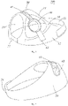
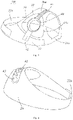
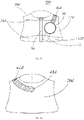
- FIG. 1 and FIG. 2 show a first preferred embodiment of the fixing device of the wireless charger according to the present invention.
- the fixing device 100 of the wireless charger comprises a supporting member wearable on a patient's body and an adjustment structure connected to the supporting member, the supporting member employing a wearable supporting member such as a supporting member with a vest structure.
- a charger fixing seat 40 is connected to one of the supporting member and the adjustment structure.
- the adjustment structure comprises an adjustment strap and a fixing buckle engaging with the adjustment strap, one end of the adjustment strap is connected to the supporting member, the other end of the adjustment strap operably brings the supporting member or the charger fixing seat to be adjusted to a position where the charger fixing seat corresponds to the implantable medical device, and the position where the adjustment strap engages with the fixing buckle is fixed relative to the supporting member.
- the charger fixing seat 40 is disposed on the adjustment strap, one end of the adjustment strap is connected to a shoulder portion or rear portion of the supporting member, and the other end of the adjustment strap operably brings the charger fixing seat to be adjusted to the position where the charger fixing seat corresponds to the implantable medical device, and is separably fastened to a front portion of the supporting member.
- the shoulder portion of the supporting member refers to a portion close to the patient's shoulder when the supporting member is worn on the patient's body.
- the rear portion of the supporting member refers to a portion close to the patient's back when the supporting member is worn on the patient's body.
- the front portion of the supporting member refers to a portion close to the patient's chest when the supporting member is worn on the patient's body.
- the supporting member comprises a shoulder supporting portion 30, and a front sheet 10 and a rear sheet 20 respectively connected to the front and rear of the shoulder supporting portion 30.
- the shoulder supporting portion 30 is a portion close to the patient's shoulder when the supporting member is worn on the patient's body and may be regarded as the shoulder portion of the supporting member;
- the front sheet 10 is a portion close to the patient's chest when the supporting member is worn on the patient's body and may be regarded as the front portion of the supporting member;
- the rear sheet 20 is a portion close to the patient's back when the supporting member is worn on the patient's body and may be regarded as the rear portion of the supporting member.
- Bottom sides of the front sheet 10 and the rear sheet 20 are connected via a left connecting portion 21 and a right connecting portion 22.
- the left connecting portion 21 and the right connecting portion 22 are used to form a shoulder cuff to be supported under the patient's armpit.
- the adjustment strap is connected to the shoulder supporting portion 30 or the rear sheet 20 of the shoulder supporting member.
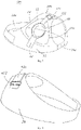
- the front sheet 10 is provided with a charging opening 11.
- the other end of the adjustment strap operably brings the charger fixing seat 40 to be adjusted to a position in the charging opening 11 corresponding to the implantable medical device, that is to say, the charging opening 11 corresponds to the position of the implantable medical device.
- the fixing buckle comprises a female hook-and-loop fastener belt and a male hook-and-loop fastener belt engaging therewith and having a fluffy surface.
- the female hook-and-loop fastener belt is disposed on one of the adjustment strap and the front sheet 10
- the male hook-and-loop fastener belt is disposed on the other of the adjustment strap and the front sheet 10.
- the adjustment strap is fixed through the separable engagement of hook-and-loop and fluffy surface to adjust the position of the charger fixing seat 40.
- the shoulder supporting portion 30 and the front sheet 10 and rear sheet 20 are directly connected together, and preferably the shoulder supporting portion 30 and the front sheet 10 and rear sheet 20 are an integral structure.
- the shoulder supporting portion 30 may also be configured to be an extensible belt, i.e., the front sheet 10 and rear sheet 20 are indirectly connected via a telescopic belt.
- the front 10 and rear sheet 20 may also be disposed symmetrical relative to the shoulder supporting portion 30 to facilitate manufacture.
- the supporting member is entirely constructed as a single-shoulder vest structure, i.e., only one shoulder supporting portion 30 is provided, namely, the shoulder supporting portion 30 on the right side.
- the charging opening 11 may be disposed on one side with the shoulder supporting portion 30.
- the left connecting portion 21 may also be configured as a belt integral with the rear sheet, and it may have a free end on which is provided a second female hook-and-loop fastener belt.
- the front sheet 10 is provided with a male hook-and-look fastener belt having a fluffy surface 12.
- the free end of the left connecting potion 21 may be adjusted according to the patient's body to a suitable position to engage with the fluffy surface 12 of the front sheet 10.
- the fluffy surface 12 is configured to be strip-shaped, triangular or arcuate and continuously distributed along the lower side of the front sheet.
- the fluffs of the fluffy surface are formed of fabric with fine fluffs protruding.
- the fine fluffs have tiny protrusions which are in the shape of short fluffs or pointed fluffs or fingers or branches or loops or honeycombs.
- the right connecting portion 22 may be configured to be an extensible connecting portion made of an extensible material or extensible structure, and may also be a belt shape. Both ends of the right connecting portion 22 are respectively connected to the front sheet 10 and rear sheet 20, and the right connecting portion 22 may be adjusted through its own extensibility to adapt to different human bodies.
- the left connecting portion 21 and right connecting portion 22 may be configured to be the same or different structures.
- the adjustment strap comprises a positioning strap 41 connected to a shoulder supporting portion 30 or rear sheet 20 and a fixing strap 42.
- the positioning strap 41 is connected to the shoulder supporting portion 30 or a position of the rear sheet 20 adjacent to the shoulder supporting portion 30.
- the fixing strap 42 is configured as the other end of the adjustment strap.
- the fixing strap 42 is separably connected to the front sheet 10.
- a preferable female hook-and-loop fastener belt may be disposed on the fixing strap 42 and engage with the fluffy surface 12 on the front sheet 10.
- the positioning strap 41 and fixing strap 42 are respectively connected at opposite sides of the fixing seat 40. Furthermore, the positioning strap 41 and fixing strap 42 may be arranged to detachably connect with the fixing seat.
- the shape of the fixing seat matches that of the wireless charger to facilitate the wireless charger to be mounted and held to the fixing seat.
- the end of the positioning strap 41 connected to the shoulder supporting portion 30 or rear sheet 20 is connected via a fixing snap 43 disposed on the shoulder supporting portion 30 or rear sheet 20 so that the positioning strap 41 can be adjusted relative to the position of the supporting member.
- an elastic band for retaining the wireless charger may be disposed on the charger fixing seat.
- the elastic band may be hooked to both sides of the charger fixing seat to limit the displacement of the wireless charger.
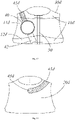
- FIG. 3 and FIG. 4 show a second preferred embodiment of the fixing device of the wireless charger of the present invention.
- Components of the fixing device 200 of the wireless charger which are denoted with the same reference numbers as the first embodiment have the same structures and functions and will not be described in detail any more.
- one shoulder supporting portion is disposed as the shoulder supporting portion 30a on the left side.
- a left connecting portion 21a in the present embodiment is structurally similar to the right connecting portion 22 in the first embodiment, and a right connecting portion 22a is structurally similar to the left connecting portion 21 in the first embodiment.
- a charging opening 11a is disposed on the left side of the supporting member. That is to say, the fixing device 100 in the first embodiment and the fixing device 200 in the second embodiment may be regarded as symmetrical structures.
- the supporting member structured as a single vest may be disposed as left-side single-shoulder or right-side single-shoulder.
- the left connecting portion and right connecting portion are structured the same and interchangeable.
- the female hook-and-loop fastener belt and the male hook-and-loop fastener belt having the fluffy surface 12 may also be disposed interchangeable, i.e., the front sheet 10 is provided with the female hook-and-loop fastener belt, and free ends of the fixing strap 42, the left connecting portion 21 and right connecting potion 22a are provided with the male hook-and-loop fastener belt engaging with the female hook-and-loop fastener belt and having the fluffy surface, which all can be implemented.
- the interchange of the left-side single-shoulder or right-side single-shoulder may also be implemented through one of single-shoulder structural forms, e.g., the supporting member may be arranged to be wearable from inside or outside so that the left-shoulder vest may be worn reversely as the right-shoulder vest.
- the male hook-and-loop fastener belt having the fluffy surface 12 may be disposed on inner and outer sides of the front sheet, and preferably disposed at the lower side of the front sheet.
- the inner and outer sides of the left connecting portion 21 or right connecting portion 22a are both provided with the female hook-and-loop fastener belt engaging with the fluffy surface 12.
- the inner and outer sides of the fixing strap 42 may also be provided with the female hook-and-loop fastener belt to engage with the fluffy surface 12.
- the fixing snap 43 may also be disposed on both inner and outer sides of the supporting member so that the positioning strap 41 can be conveniently connected when the supporting member is worn reversely.
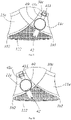
- FIG. 5 and FIG. 6 show a third preferred embodiment of the fixing device of the wireless charger of the present invention.
- Components of the fixing device 300 of the wireless charger which are denoted with the same reference numbers as the second embodiment have the same structures and functions and will not be described in detail any more.
- the shoulder supporting portion 30b is also provided with the shoulder fluffy surface 31.
- the positioning strap 41b is provided with the female hook-and-loop fastener belt.
- the positioning strap 41b is fixed relative to the position of the shoulder supporting portion 41b in a way that the female hook-and-loop fastener belt on the positioning strap 41b engages with the shoulder fluffy surface 31 on the shoulder supporting portion 30b, thereby preventing the displacement of the charger fixing seat 40 during use.
- the positioning strap 41b is fixed first, and then the fixing strap 42 is connected to the fluffy surface 12 of the front sheet 10.
- FIG. 7 and FIG. 8 show a fourth preferred embodiment of the fixing device of the wireless charger of the present invention.
- Components of the fixing device 400 of the wireless charger which are denoted with the same reference numbers as the second embodiment have the same structures and functions and will not be described in detail any more.
- the positioning strap 41c is configured adjustable in length.
- the positioning strap 41c is connected to a position of the rear sheet 20 adjacent to the shoulder fixing portion 30b.
- a fixing ring 412 is fixed on the shoulder fixing portion 30b or rear sheet 20.
- One end of the positioning strap 41c is connected to the fixing ring 412.
- An adjustable ring 411 is disposed on the positioning strap 41c.
- the length of the positioning strap 41c connected to the charger fixing seat 40 can be adjusted by operating the adjustable ring 411 and the positioning strap 41c. Hence, after the position of the charger fixing seat 40 is adjusted, the fixing strap 42 is connected to the fluffy surface 12 of the front sheet 10.
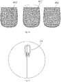
- FIG. 9 and FIG. 10 show a fifth preferred embodiment of the fixing device of the wireless charger of the present invention.
- Components of the fixing device 500 of the wireless charger which are denoted with the same reference numbers as the second embodiment have the same structures and functions and will not be described in detail any more.
- the charging opening 11a is filled with a mesh-like fabric to facilitate heat dissipation upon charging.
- the charging opening 11a may be disposed on the left side or right side relative to the patient's body.
- FIG. 11 and FIG. 12 show a sixth preferred embodiment of the fixing device of the wireless charger according to the present invention.
- the fixing device 600 of the wireless charger comprises a supporting member wearable on a patient's body and having a vest structure.
- the supporting member comprises a shoulder supporting portion 30d, and a front sheet 10d and a rear sheet 20d respectively connected to the front and rear of the shoulder supporting portion 30d. Bottom sides of the front sheet 10d and the rear sheet 20d are connected via a left connecting portion and a right connecting portion.
- the left connecting portion and the right connecting portion are used to form a shoulder cuff to be supported under the patient's armpit.
- the fixing device of the wireless charger further comprises an adjustment strap provided with a charger fixing seat 40.
- the adjustment strap is connected to the shoulder supporting portion 30d or the rear sheet 20d of the shoulder supporting member.
- the front sheet 10d is provided with a charging opening 11d.
- the other end of the adjustment strap operably brings the charger fixing seat 40 to be adjusted to a position in the charging opening 11d corresponding to the implantable medical device, and is separably connected to the front sheet 10 of the shoulder supporting member.
- the supporting member is entirely configured as a dual-shoulder vest structure, i.e., two shoulder supporting portions 30d are provided with one on each of the left side and right side.
- the charging opening 11d may also be arranged along both the left and right sides, e.g., the supporting member is entirely configured a left-right symmetrical structure.
- the shoulder supporting portion 30d and the front sheet 10d and rear sheet 20d are directly connected together, and preferably the shoulder supporting portion 30d and the front sheet 10d and rear sheet 20d are an integral structure.
- the left and right connecting portions may also be directly connected to the front sheet 10d and rear sheet 20d.
- the front sheet 10d is configured as a two-half structure from both sides.
- a slide fastener structure 50 is disposed between the both sides.
- the put-on and put-off of the supporting member can be achieved by operating the slide fastener structure 50.
- the front sheet 10d comprises an upper portion and a lower portion spaced apart, i.e., the charging opening 11d spaces the upper portion of the front sheet 10d from the lower portion of the front sheet 10d.
- the fluffy surface is disposed on the lower portion of the front sheet 10d.
- the positioning strap 41d may also be configured as an elastic band whose one end is fixed to the shoulder supporting portion 30d or rear sheet 20d.
- the configuration of the fixing strap 42 and the connection manner with the front sheet 10d may be the same as the previous embodiments and will not be detailed any more here.
- FIG. 13 and FIG. 14 show a seventh preferred embodiment of the fixing device of the wireless charger according to the present invention.
- Components of the fixing device 700 of the wireless charger which are denoted with the same reference numbers as the sixth embodiment have the same structures and functions and will not be described in detail any more.
- the positioning strap 41c is configured the same as the fourth embodiment and is adjustable in length.
- the shoulder fixing portion 30d or rear sheet 20d is fixed with a fixing ring 412.
- One end of the positioning strap 41c is connected to the fixing ring 412.
- the positioning strap 41c is provided with an adjusting ring 411.
- the length of the positioning strap 41c connected to the charger fixing seat 40 can be adjusted by operating the adjustment ring 411 and the positioning strap 41c.
- the adjustment ring 411 may be considered as a length adjuster, and it moves in a lengthwise direction of the positioning strap 41c to adjust the distance between a connection end of the positioning strap 41c connected to the supporting member and the charger fixing seat 40. Hence, after the position of the charger fixing seat 40 is adjusted, the fixing strap 42 is connected to the front sheet 10.
- the fixing ring 412 may be connected to the lower side of the rear sheet 20d via the fixing snap.
- FIG. 15 through FIG. 18 show an eighth preferred embodiment of the fixing device of the wireless charger according to the present invention.
- Components of the fixing device 800 of the wireless charger which are denoted with the same reference numbers as the sixth embodiment have the same structures and functions and will not be described in detail any more.
- the positioning strap 41d is configured as a strap of an extensible material, and its one end connected to the rear sheet 20d is connected to the rear sheet 20d via a fixing snap 43d.
- the fixing snap 43d is disposed in the middle of the rear sheet 20d.
- the positioning strap 41d may selectively bypass from the left shoulder or right shoulder so that the charger fixing seat can be conveniently adjusted to the left side or right side of the patient's body.
- FIG. 19 through FIG. 22 show a ninth preferred embodiment of the fixing device of the wireless charger according to the present invention.
- the fixing 900 of the wireless charger comprises a supporting member wearable on a patient's body and having a vest structure.
- the supporting member comprises a shoulder supporting portion 30e, and a front sheet and a front sheet 20e respectively connected to the front and rear of the shoulder supporting portion 30e. Bottom sides of the front sheet and the rear sheet 20e are connected via a left connecting portion 21e and a right connecting portion.
- the left connecting portion 21e and the right connecting portion are used to form a shoulder cuff to be supported under the patient's armpit.
- the fixing device of the wireless charger further comprises an adjustment strap provided with a charger fixing seat 40.
- the configuration of the adjustment strap is similar to that of the sixth embodiment and will not be detailed any more here.
- the supporting member is entirely configured as a dual-shoulder vest structure, i.e., two shoulder supporting portions 30e are provided with one on each of the left side and right side.
- the charging opening 11e may also be arranged along both the left and right sides, e.g., the supporting member is entirely configured a left-right symmetrical structure.
- the front sheet comprises a left front sheet 101 and a right front sheet 102 which are partially overlappable from left to right.
- the shoulder supporting portion 30d and the front sheet 10d and rear sheet 20d are directly connected together, and preferably the shoulder supporting portion 30e and the left front sheet 101 and right front sheet 102 and rear sheet 10e are an integral structure.
- the left connecting portion 21e and right connecting portion may be configured as an extensible belt connecting the left front sheet 101 with the rear sheet 10e and an extensible belt connecting the right front sheet 102 with the rear sheet 10e, respectively.
- the left front sheet 101 is provided with a first male hook-and-loop fastener belt having a fluffy surface 121.
- An outer side of the right front sheet 102 is provided with a second male hook-and-loop fastener belt having a fluffy surface 122.
- An inner side of the right front sheet 102 is provided with a third female hook-and-loop fastener belt engaging with the fluffy surface 121.
- the left front sheet 101 and right front sheet 102 achieve detachable connection of the two via the engagement of the third female hook-and-loop fastener belt and the fluffy surface 121 so that the size of the supporting member may be adjusted according to the patient's body.
- the fixing strap 42 may also be connected to the fluffy surface 122 of the right front sheet 102 via the female hook-and-loop fastener belt to achieve affixation of the charger fixing seat 40 relative to the supporting member.
- the left-right overlappable manner of the left front sheet 101 and right front sheet 102 are interchangeable.
- the charger fixing seat 40 may be fixed in the charging opening on the left side or in the charging opening on the right side via the positioning strap 41c and fixing strap 42.
- FIG. 23 through FIG. 27 show a tenth preferred embodiment of the fixing device of the wireless charger according to the present invention.
- the fixing device 1000 of the wireless charger comprises a supporting member wearable on a patient's body and an adjustment structure connected to the supporting member.
- a charger fixing seat 40f is connected to one of the supporting member and the adjustment structure.
- the adjustment structure comprises an adjustment strap 62 and a fixing buckle 61 engaging with the adjustment strap 62, one end of the adjustment strap 62 is connected to the supporting member, the other end of the adjustment strap 62 operably brings the supporting member or the charger fixing seat to be adjusted to a position where the charger fixing seat corresponds to the implantable medical device, and the position where the adjustment strap 62 engages with the fixing buckle 61 is fixed relative to the supporting member.
- the charger fixing seat 40f is connected to the supporting member, one end of the fixing buckle 61 is connected to the supporting member, and the other end of the fixing buckle 61 is movably connected to the adjustment strap 62.
- the fixing buckle 61 comprises a male snap and a female snap which are detachably connected.
- the male snap and female snap are respectively connected to the supporting member and the adjustment strap 61.
- the patient may conveniently put on or put off the fixing device by opening the fixing buckle 61.
- the fixing buckle 61 may be configured as a plug-in buckle, a male buckle or a female buckle of the plug-in buckle is connected to the adjustment ring.
- the other end of the adjustment strap 62 passes through the adjustment ring and is configured as a free end.
- the position of the supporting member may be adjusted by pulling of the free end of the adjustment strap 62, and the fixing buckle 61 will bring the supporting member to move, until the charger fixing seat 40f corresponds to the position of the implantable medical device. Locking is achieved by releasing the adjustment strap 62, i.e., the engagement position of the adjustment strap 62 and the fixing buckle 61 is fixed relative to the supporting member.
- the supporting member comprises a supporting portion 30f, and a front sheet 10f and a rear sheet 20f connected to the front and rear of the shoulder supporting portion 30f, respectively. Bottom sides of the front sheet 10f and the rear sheet 20f are connected via a left connecting portion and a right connecting portion.
- the shoulder supporting portion, the front sheet and rear sheet here are also regarded as the shoulder of the supporting member, the front of the supporting member and the rear of the supporting member.
- the left connecting portion and the right connecting portion are used to form a shoulder cuff to be supported under the patient's armpit.
- the right connecting portion 22f forms the shoulder cuff
- the left connecting portion is configured as the adjustment structure.
- One end of the adjustment strap 62 is connected to the rear sheet 20f, and the fixing buckle 61 is connected between the front sheet 10f and the adjustment strap 62.
- the position of the charger fixing seat 40f is adjusted via the left connecting portion serving as the adjustment structure, so that the structure of the whole fixing device is simpler, the costs are lower and the use is more convenient.
- the shoulder supporting portion 30f and the right connecting portion 22f are both configured as elastic extensible belts to facilitate adaptation to patients with different body shapes and facilitate the patients to adjust the position of the charger fixing seat 40f.
- the charger fixing seat 40f is configured as a storage bag.
- the storage bag is connected between the shoulder supporting portion 30f and the front sheet 10f to facilitate receiving the wireless charger.
- the storage bag comprises an outer bag 401 located outside and an inner bag 403 located inside.
- a partition layer 402 is disposed between the outer bag 401 and inner bag 403.
- the shoulder supporting portion 30f is connected to the partition layer 402.
- the storage bag is disposed both inside and outside the supporting member to achieve wearing of the fixing device from inside and from outside so that the charger fixing seat 40f is fixed to the left chest and right chest.
- the storage bag comprises an outer bag located outside and an inner bag located inside.
- the inner bag and outer bag are communicated with each other, that is, the storage bag is communicated from outside and inside without a partition layer being disposed. More materials are saved with one storage bag which may receive the wireless charger from both inside and outside.
- the storage bag may be made of a mesh-like fabric.
- a female hook-and-loop fastener belt is disposed on one of an outer side of the storage bag and an inner side of the storage bag
- a male hook-and-loop fastener belt having a fluffy surface is disposed on the other of the outer side of the storage bag and inner side of the storage bag
- the female hook-and-loop fastener belt separably engages with the male hook-and-loop fastener belt to close at least one portion of the bag mouth of the storage bag.
- one of the outer side of the storage bag and the shoulder supporting portion 30f is provided with a female hook-and-loop fastener belt
- the other of the outer side of the storage bag and the shoulder supporting portion 30f is provided with a male hook-and-loop fastener belt having a fluffy surface
- the female hook-and-loop fastener belt separably engages with the male hook-and-loop fastener belt to close at least one portion of the bag mouth of the storage bag.
- the front sheet 10f consists of an inner layer and an outer layer, and at least partial edge of the charger fixing seat is connected between the inner layer and outer layer so that the fixing device does not affect the patient's body when worn.
- the edge of each of the front sheet 10f, the rear sheet 20f and the charger fixing seat 40f may be provided with a closure edge structure 18 to make the patient more comfortable while wearing the fixing device and meanwhile make the appearance more aesthetic.
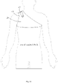
- the overall length L of the front sheet and rear sheet is substantially in a range of 200-250mm, and the front sheet and rear sheet may also be made of a mesh-like fabric, no matter whether the fabric is elastic or not.
- the left connecting portion and right connecting portion disposed under the armpit has a length substantially in a range of 80-120mm, and a width in a range of 30-50mm.
- the shoulder supporting portion has a length substantially in a range of 90-130mm and a width in a range of 30-50mm.
- the adjustment strap has a length substantially in a range of 360-440mm and a width in a range of 30-50mm.
Claims (6)
- Befestigungsvorrichtung (100, 200, 300, 400, 500, 600, 700, 800, 900, 1000) eines drahtlosen Ladegeräts für eine implantierte medizinische Vorrichtung, die Befestigungsvorrichtung umfassend ein Halteelement, das am Körper eines Patienten getragen werden kann, und eine Einstellstruktur, die mit dem Halteelement verbunden ist, wobei ein Ladegerät-Befestigungssitz (40, 40f) mit einem von dem Halteelement oder der Einstellstruktur verbunden ist, wobei die Einstellstruktur einen Einstellriemen (41, 41b, 41c, 41d, 42, 62) und eine Befestigungsschnalle (12, 61), die in den Einstellriemen (41, 41b, 41c, 41d, 42, 62) eingreift, wobei ein Ende des Einstellriemens (41, 41b, 41c, 41d, 42, 62) mit dem Halteelement verbunden ist, das andere Ende des Einstellriemens (62, 41b, 41c, 41d, 41, 62) das Halteelement oder den einzustellenden Ladegerät-Befestigungssitz (40, 40f) in eine Position bringt, in der der Ladegerät-Befestigungssitz (40, 40f) der implantierten medizinischen Vorrichtung entspricht, und eine Position, in der der Einstellriemen mit der Befestigungsschnalle eingreift, eingestellt und arretiert werden kann, wobei der Ladegerät-Befestigungssitz (40, 40f) mit dem Halteelement verbunden ist, ein Ende der Befestigungsschnalle (61) an dem Halteelement befestigt ist und das andere Ende der Befestigungsschnalle (61) beweglich mit dem Einstellriemen (62) verbunden ist, wobei die Befestigungsschnalle (61) eine Stiftraste und eine Buchsenraste umfasst, die lösbar verbunden sind, und die Stiftraste und die Buchsenraste jeweils mit dem Halteelement und dem Einstellriemen verbunden sind, dadurch gekennzeichnet, dass das Halteelement einen linken Verbindungsabschnitt (21, 21a, 21e) und einen rechten Verbindungsabschnitt (22, 22a, 22f) umfasst, Unterseiten eines vorderen Abschnitts des Halteelements und eines hinteren Abschnitts des Halteelements über den linken Verbindungsabschnitt (21, 21a, 21e) und den rechten Verbindungsabschnitt (22, 22a, 22f) verbunden sind, einer von dem linken Verbindungsabschnitt (21, 21a, 21e) und dem rechten Verbindungsabschnitt (22, 22a, 22f) verwendet wird, um eine Schultermanschette zu bilden, die unter der Achselhöhle des Patienten gehalten werden soll, der andere von dem linken und dem rechten Verbindungsabschnitt als Einstellriemen (62) konfiguriert ist, ein Ende des Einstellriemens (62) mit dem hinteren Abschnitt des Halteelements verbunden ist, und die Befestigungsschnalle (61) zwischen dem vorderen Abschnitt des Halteelements und dem Einstellriemen (62) verbunden ist.
- Befestigungsvorrichtung eines drahtlosen Ladegeräts nach Anspruch 1, wobei ein Schulterabschnitt des Halteelements und entweder der linke Verbindungsabschnitt (21, 21a, 21e) oder der rechte Verbindungsabschnitt (22, 22a, 22f) beide als elastische dehnbare Riemen konfiguriert sind.
- Befestigungsvorrichtung eines drahtlosen Ladegeräts nach Anspruch 1, wobei der Ladegerät-Befestigungssitz als eine Aufbewahrungstasche konfiguriert ist und die Aufbewahrungstasche zwischen der Schulter des Halteelements und dem vorderen Abschnitt des Halteelements verbunden ist, wobei die Aufbewahrungstasche eine äußere Tasche, die sich außen befindet, und eine innere Tasche, die sich darin befindet, umfasst, wobei eine Trennschicht zwischen der äußeren Tasche und der inneren Tasche angeordnet ist, und der Schulterabschnitt des Halteelements mit der Trennschicht verbunden ist.
- Befestigungsvorrichtung eines drahtlosen Ladegeräts nach Anspruch 1, wobei der Ladegerät-Befestigungssitz als eine Aufbewahrungstasche konfiguriert ist und die Aufbewahrungstasche zwischen der Schulter des Halteelements und dem vorderen Abschnitt des Halteelements verbunden ist, wobei die Aufbewahrungstasche eine äußere Tasche, die sich außen befindet, und eine innere Tasche, die sich darin befindet, umfasst und die äußere Tasche mit der inneren Tasche in Verbindung ist.
- Befestigungsvorrichtung eines drahtlosen Ladegeräts nach Anspruch 3 oder 4, wobei ein vorderer Abschnitt des Halteelements aus einer inneren Schicht und einer äußeren Schicht besteht und zumindest ein Teilrand des Ladegerät-Befestigungssitzes zwischen der inneren Schicht und der äußeren Schicht verbunden ist.
- Drahtlose Ladevorrichtung, wobei die drahtlose Ladevorrichtung ein drahtloses Ladegerät und die Befestigungsvorrichtung (100, 200, 300, 400, 500, 600, 700, 800, 900, 1000) des drahtlosen Ladegeräts nach einem der Ansprüche 1-5 umfasst, das drahtlose Ladegerät abnehmbar an dem Ladegerät-Befestigungssitz (40, 40f) angebracht ist und das drahtlose Ladegerät ein Ladefeld erzeugen kann, um die implantierte medizinische Vorrichtung aufzuladen.
Priority Applications (1)
| Application Number | Priority Date | Filing Date | Title |
|---|---|---|---|
| EP21196951.4A EP3944873B1 (de) | 2017-12-14 | 2018-12-12 | Fixiervorrichtung für ein drahtloses ladegerät und drahtloses ladegerät |
Applications Claiming Priority (3)
| Application Number | Priority Date | Filing Date | Title |
|---|---|---|---|
| CN201711341212 | 2017-12-14 | ||
| CN201811474609.7A CN109954211B (zh) | 2017-12-14 | 2018-12-04 | 无线充电器的固定装置及无线充电装置 |
| PCT/CN2018/120494 WO2019114734A1 (zh) | 2017-12-14 | 2018-12-12 | 无线充电器的固定装置及无线充电装置 |
Related Child Applications (2)
| Application Number | Title | Priority Date | Filing Date |
|---|---|---|---|
| EP21196951.4A Division-Into EP3944873B1 (de) | 2017-12-14 | 2018-12-12 | Fixiervorrichtung für ein drahtloses ladegerät und drahtloses ladegerät |
| EP21196951.4A Division EP3944873B1 (de) | 2017-12-14 | 2018-12-12 | Fixiervorrichtung für ein drahtloses ladegerät und drahtloses ladegerät |
Publications (3)
| Publication Number | Publication Date |
|---|---|
| EP3725367A1 EP3725367A1 (de) | 2020-10-21 |
| EP3725367A4 EP3725367A4 (de) | 2021-01-06 |
| EP3725367B1 true EP3725367B1 (de) | 2022-11-16 |
Family
ID=66818927
Family Applications (1)
| Application Number | Title | Priority Date | Filing Date |
|---|---|---|---|
| EP18888136.1A Active EP3725367B1 (de) | 2017-12-14 | 2018-12-12 | Fixiervorrichtung für ein drahtloses ladegerät und drahtloses ladegerät |
Country Status (4)
| Country | Link |
|---|---|
| US (1) | US11554266B2 (de) |
| EP (1) | EP3725367B1 (de) |
| CN (1) | CN109954211B (de) |
| WO (1) | WO2019114068A1 (de) |
Families Citing this family (1)
| Publication number | Priority date | Publication date | Assignee | Title |
|---|---|---|---|---|
| CN112156363A (zh) * | 2020-10-10 | 2021-01-01 | 北京品驰医疗设备有限公司 | 一种充电器体外固定装置 |
Family Cites Families (19)
| Publication number | Priority date | Publication date | Assignee | Title |
|---|---|---|---|---|
| US3942535A (en) * | 1973-09-27 | 1976-03-09 | G. D. Searle & Co. | Rechargeable tissue stimulating system |
| US5991665A (en) * | 1997-09-18 | 1999-11-23 | Sulzer Intermedics Inc. | Self-cooling transcutaneous energy transfer system for battery powered implantable device |
| KR100606307B1 (ko) * | 2001-05-23 | 2006-07-28 | 안태영 | 인체 이식 기구용 무접촉식 동력 전달 장치 |
| WO2005104779A2 (en) * | 2004-04-28 | 2005-11-10 | Transoma Medical, Inc. | Implantable medical devices and related methods |
| US7738965B2 (en) * | 2006-04-28 | 2010-06-15 | Medtronic, Inc. | Holster for charging pectorally implanted medical devices |
| US8626297B2 (en) | 2007-09-20 | 2014-01-07 | Boston Scientific Neuromodulation Corporation | Apparatus and methods for charging an implanted medical device power source |
| US20090157113A1 (en) * | 2007-12-18 | 2009-06-18 | Ethicon Endo-Surgery, Inc. | Wearable elements for implantable restriction systems |
| US20090251101A1 (en) * | 2008-04-02 | 2009-10-08 | Medtronic, Inc. | Holster for charging pectorally-implanted medical devices |
| US8204602B2 (en) * | 2008-04-23 | 2012-06-19 | Medtronic, Inc. | Recharge system and method for deep or angled devices |
| CN102157990B (zh) * | 2011-03-31 | 2013-08-28 | 深圳市锘特达科技发展有限公司 | 用于植入式医疗装置的无线充电方法及无线充电设备 |
| CA2837877A1 (en) * | 2011-06-06 | 2012-12-13 | Witricity Corporation | Wireless energy transfer for implantable devices |
| US8612015B2 (en) | 2012-03-20 | 2013-12-17 | James Dan Knifong, SR. | Molding device to precisely hold a recharge antenna |
| WO2014145667A2 (en) * | 2013-03-15 | 2014-09-18 | Vascor, Inc. | Thoracic aorta ventricular assist system |
| CN204218197U (zh) * | 2014-10-21 | 2015-03-25 | 北京品驰医疗设备有限公司 | 一种充电用背带结构 |
| CN205516007U (zh) | 2016-02-04 | 2016-08-31 | 合肥市第二人民医院 | 起搏器植入后压迫盐袋固定带 |
| EP3432975B1 (de) * | 2016-03-21 | 2024-02-14 | Nalu Medical, Inc. | Vorrichtungen zur positionierung externer vorrichtungen in bezug auf implantierte vorrichtungen |
| CN105762946B (zh) * | 2016-04-08 | 2018-10-16 | 电子科技大学 | 一种基于射频接收和相位补偿转发的无线充电方法及装置 |
| CN107349525B (zh) * | 2017-05-17 | 2018-11-23 | 苏州景昱医疗器械有限公司 | 无线充电器的固定装置及无线充电装置 |
| CN209347933U (zh) * | 2017-12-14 | 2019-09-06 | 苏州景昱医疗器械有限公司 | 用于植入医疗装置的无线充电器的固定装置及无线充电装置 |
-
2018
- 2018-01-08 WO PCT/CN2018/071722 patent/WO2019114068A1/zh active Application Filing
- 2018-12-04 CN CN201811474609.7A patent/CN109954211B/zh active Active
- 2018-12-12 US US16/772,795 patent/US11554266B2/en active Active
- 2018-12-12 EP EP18888136.1A patent/EP3725367B1/de active Active
Also Published As
| Publication number | Publication date |
|---|---|
| EP3725367A1 (de) | 2020-10-21 |
| US11554266B2 (en) | 2023-01-17 |
| CN109954211A (zh) | 2019-07-02 |
| CN109954211B (zh) | 2024-04-26 |
| WO2019114068A1 (zh) | 2019-06-20 |
| US20210162221A1 (en) | 2021-06-03 |
| EP3725367A4 (de) | 2021-01-06 |
Similar Documents
| Publication | Publication Date | Title |
|---|---|---|
| US11938327B2 (en) | Devices and methods for positioning external devices in relation to implanted devices | |
| US7925357B2 (en) | Holster for charging pectorally implanted medical devices | |
| US20120012630A1 (en) | Charger belt | |
| EP2074969B1 (de) | Tragbare Elemente für implantierbare Einschränkungssysteme | |
| US8676337B2 (en) | Recharge system and method for deep or angled devices | |
| US8428746B2 (en) | Moldable charger with shape-sensing means for an implantable pulse generator | |
| US20090251101A1 (en) | Holster for charging pectorally-implanted medical devices | |
| WO2010059377A1 (en) | Wearable elements for intra-gastric satiety creation systems | |
| EP3725367B1 (de) | Fixiervorrichtung für ein drahtloses ladegerät und drahtloses ladegerät | |
| WO2022073308A1 (zh) | 一种充电器体外固定装置 | |
| EP3944873B1 (de) | Fixiervorrichtung für ein drahtloses ladegerät und drahtloses ladegerät | |
| CN211634900U (zh) | 一种充电用简易背带以及体外无线充电系统 | |
| CN209347933U (zh) | 用于植入医疗装置的无线充电器的固定装置及无线充电装置 | |
| US10967192B2 (en) | Systems and methods for charging a medical device implanted into a patient | |
| CN216725531U (zh) | 一种充电携具 | |
| CN219304541U (zh) | 无线充/供电辅助装置及充/供电系统 | |
| CN113209480A (zh) | 一种充电携具 | |
| CN116111735A (zh) | 无线充/供电辅助装置及充/供电系统 |
Legal Events
| Date | Code | Title | Description |
|---|---|---|---|
| STAA | Information on the status of an ep patent application or granted ep patent |
Free format text: STATUS: THE INTERNATIONAL PUBLICATION HAS BEEN MADE |
|
| PUAI | Public reference made under article 153(3) epc to a published international application that has entered the european phase |
Free format text: ORIGINAL CODE: 0009012 |
|
| STAA | Information on the status of an ep patent application or granted ep patent |
Free format text: STATUS: REQUEST FOR EXAMINATION WAS MADE |
|
| 17P | Request for examination filed |
Effective date: 20200612 |
|
| AK | Designated contracting states |
Kind code of ref document: A1 Designated state(s): AL AT BE BG CH CY CZ DE DK EE ES FI FR GB GR HR HU IE IS IT LI LT LU LV MC MK MT NL NO PL PT RO RS SE SI SK SM TR |
|
| AX | Request for extension of the european patent |
Extension state: BA ME |
|
| A4 | Supplementary search report drawn up and despatched |
Effective date: 20201208 |
|
| RIC1 | Information provided on ipc code assigned before grant |
Ipc: H02J 7/00 20060101ALI20201202BHEP Ipc: A61N 1/36 20060101ALI20201202BHEP Ipc: A61N 1/378 20060101AFI20201202BHEP Ipc: A61N 1/362 20060101ALN20201202BHEP |
|
| DAV | Request for validation of the european patent (deleted) | ||
| DAX | Request for extension of the european patent (deleted) | ||
| GRAP | Despatch of communication of intention to grant a patent |
Free format text: ORIGINAL CODE: EPIDOSNIGR1 |
|
| STAA | Information on the status of an ep patent application or granted ep patent |
Free format text: STATUS: GRANT OF PATENT IS INTENDED |
|
| RIC1 | Information provided on ipc code assigned before grant |
Ipc: A61N 1/362 20060101ALN20220706BHEP Ipc: A61N 1/36 20060101ALI20220706BHEP Ipc: H02J 50/00 20160101ALI20220706BHEP Ipc: A61N 1/378 20060101AFI20220706BHEP |
|
| INTG | Intention to grant announced |
Effective date: 20220804 |
|
| GRAS | Grant fee paid |
Free format text: ORIGINAL CODE: EPIDOSNIGR3 |
|
| GRAA | (expected) grant |
Free format text: ORIGINAL CODE: 0009210 |
|
| STAA | Information on the status of an ep patent application or granted ep patent |
Free format text: STATUS: THE PATENT HAS BEEN GRANTED |
|
| AK | Designated contracting states |
Kind code of ref document: B1 Designated state(s): AL AT BE BG CH CY CZ DE DK EE ES FI FR GB GR HR HU IE IS IT LI LT LU LV MC MK MT NL NO PL PT RO RS SE SI SK SM TR |
|
| REG | Reference to a national code |
Ref country code: GB Ref legal event code: FG4D |
|
| REG | Reference to a national code |
Ref country code: CH Ref legal event code: EP |
|
| REG | Reference to a national code |
Ref country code: DE Ref legal event code: R096 Ref document number: 602018043246 Country of ref document: DE |
|
| REG | Reference to a national code |
Ref country code: IE Ref legal event code: FG4D |
|
| REG | Reference to a national code |
Ref country code: AT Ref legal event code: REF Ref document number: 1531404 Country of ref document: AT Kind code of ref document: T Effective date: 20221215 |
|
| REG | Reference to a national code |
Ref country code: LT Ref legal event code: MG9D |
|
| REG | Reference to a national code |
Ref country code: NL Ref legal event code: MP Effective date: 20221116 |
|
| REG | Reference to a national code |
Ref country code: AT Ref legal event code: MK05 Ref document number: 1531404 Country of ref document: AT Kind code of ref document: T Effective date: 20221116 |
|
| PG25 | Lapsed in a contracting state [announced via postgrant information from national office to epo] |
Ref country code: SE Free format text: LAPSE BECAUSE OF FAILURE TO SUBMIT A TRANSLATION OF THE DESCRIPTION OR TO PAY THE FEE WITHIN THE PRESCRIBED TIME-LIMIT Effective date: 20221116 Ref country code: PT Free format text: LAPSE BECAUSE OF FAILURE TO SUBMIT A TRANSLATION OF THE DESCRIPTION OR TO PAY THE FEE WITHIN THE PRESCRIBED TIME-LIMIT Effective date: 20230316 Ref country code: NO Free format text: LAPSE BECAUSE OF FAILURE TO SUBMIT A TRANSLATION OF THE DESCRIPTION OR TO PAY THE FEE WITHIN THE PRESCRIBED TIME-LIMIT Effective date: 20230216 Ref country code: LT Free format text: LAPSE BECAUSE OF FAILURE TO SUBMIT A TRANSLATION OF THE DESCRIPTION OR TO PAY THE FEE WITHIN THE PRESCRIBED TIME-LIMIT Effective date: 20221116 Ref country code: FI Free format text: LAPSE BECAUSE OF FAILURE TO SUBMIT A TRANSLATION OF THE DESCRIPTION OR TO PAY THE FEE WITHIN THE PRESCRIBED TIME-LIMIT Effective date: 20221116 Ref country code: ES Free format text: LAPSE BECAUSE OF FAILURE TO SUBMIT A TRANSLATION OF THE DESCRIPTION OR TO PAY THE FEE WITHIN THE PRESCRIBED TIME-LIMIT Effective date: 20221116 Ref country code: AT Free format text: LAPSE BECAUSE OF FAILURE TO SUBMIT A TRANSLATION OF THE DESCRIPTION OR TO PAY THE FEE WITHIN THE PRESCRIBED TIME-LIMIT Effective date: 20221116 |
|
| PG25 | Lapsed in a contracting state [announced via postgrant information from national office to epo] |
Ref country code: RS Free format text: LAPSE BECAUSE OF FAILURE TO SUBMIT A TRANSLATION OF THE DESCRIPTION OR TO PAY THE FEE WITHIN THE PRESCRIBED TIME-LIMIT Effective date: 20221116 Ref country code: PL Free format text: LAPSE BECAUSE OF FAILURE TO SUBMIT A TRANSLATION OF THE DESCRIPTION OR TO PAY THE FEE WITHIN THE PRESCRIBED TIME-LIMIT Effective date: 20221116 Ref country code: LV Free format text: LAPSE BECAUSE OF FAILURE TO SUBMIT A TRANSLATION OF THE DESCRIPTION OR TO PAY THE FEE WITHIN THE PRESCRIBED TIME-LIMIT Effective date: 20221116 Ref country code: IS Free format text: LAPSE BECAUSE OF FAILURE TO SUBMIT A TRANSLATION OF THE DESCRIPTION OR TO PAY THE FEE WITHIN THE PRESCRIBED TIME-LIMIT Effective date: 20230316 Ref country code: HR Free format text: LAPSE BECAUSE OF FAILURE TO SUBMIT A TRANSLATION OF THE DESCRIPTION OR TO PAY THE FEE WITHIN THE PRESCRIBED TIME-LIMIT Effective date: 20221116 Ref country code: GR Free format text: LAPSE BECAUSE OF FAILURE TO SUBMIT A TRANSLATION OF THE DESCRIPTION OR TO PAY THE FEE WITHIN THE PRESCRIBED TIME-LIMIT Effective date: 20230217 |
|
| PG25 | Lapsed in a contracting state [announced via postgrant information from national office to epo] |
Ref country code: NL Free format text: LAPSE BECAUSE OF FAILURE TO SUBMIT A TRANSLATION OF THE DESCRIPTION OR TO PAY THE FEE WITHIN THE PRESCRIBED TIME-LIMIT Effective date: 20221116 |
|
| PG25 | Lapsed in a contracting state [announced via postgrant information from national office to epo] |
Ref country code: SM Free format text: LAPSE BECAUSE OF FAILURE TO SUBMIT A TRANSLATION OF THE DESCRIPTION OR TO PAY THE FEE WITHIN THE PRESCRIBED TIME-LIMIT Effective date: 20221116 Ref country code: RO Free format text: LAPSE BECAUSE OF FAILURE TO SUBMIT A TRANSLATION OF THE DESCRIPTION OR TO PAY THE FEE WITHIN THE PRESCRIBED TIME-LIMIT Effective date: 20221116 Ref country code: EE Free format text: LAPSE BECAUSE OF FAILURE TO SUBMIT A TRANSLATION OF THE DESCRIPTION OR TO PAY THE FEE WITHIN THE PRESCRIBED TIME-LIMIT Effective date: 20221116 Ref country code: DK Free format text: LAPSE BECAUSE OF FAILURE TO SUBMIT A TRANSLATION OF THE DESCRIPTION OR TO PAY THE FEE WITHIN THE PRESCRIBED TIME-LIMIT Effective date: 20221116 Ref country code: CZ Free format text: LAPSE BECAUSE OF FAILURE TO SUBMIT A TRANSLATION OF THE DESCRIPTION OR TO PAY THE FEE WITHIN THE PRESCRIBED TIME-LIMIT Effective date: 20221116 |
|
| REG | Reference to a national code |
Ref country code: CH Ref legal event code: PL |
|
| REG | Reference to a national code |
Ref country code: DE Ref legal event code: R097 Ref document number: 602018043246 Country of ref document: DE |
|
| REG | Reference to a national code |
Ref country code: BE Ref legal event code: MM Effective date: 20221231 |
|
| PG25 | Lapsed in a contracting state [announced via postgrant information from national office to epo] |
Ref country code: SK Free format text: LAPSE BECAUSE OF FAILURE TO SUBMIT A TRANSLATION OF THE DESCRIPTION OR TO PAY THE FEE WITHIN THE PRESCRIBED TIME-LIMIT Effective date: 20221116 Ref country code: LU Free format text: LAPSE BECAUSE OF NON-PAYMENT OF DUE FEES Effective date: 20221212 Ref country code: AL Free format text: LAPSE BECAUSE OF FAILURE TO SUBMIT A TRANSLATION OF THE DESCRIPTION OR TO PAY THE FEE WITHIN THE PRESCRIBED TIME-LIMIT Effective date: 20221116 |
|
| PLBE | No opposition filed within time limit |
Free format text: ORIGINAL CODE: 0009261 |
|
| STAA | Information on the status of an ep patent application or granted ep patent |
Free format text: STATUS: NO OPPOSITION FILED WITHIN TIME LIMIT |
|
| 26N | No opposition filed |
Effective date: 20230817 |
|
| GBPC | Gb: european patent ceased through non-payment of renewal fee |
Effective date: 20230216 |
|
| PG25 | Lapsed in a contracting state [announced via postgrant information from national office to epo] |
Ref country code: LI Free format text: LAPSE BECAUSE OF NON-PAYMENT OF DUE FEES Effective date: 20221231 Ref country code: IE Free format text: LAPSE BECAUSE OF NON-PAYMENT OF DUE FEES Effective date: 20221212 Ref country code: CH Free format text: LAPSE BECAUSE OF NON-PAYMENT OF DUE FEES Effective date: 20221231 |
|
| PG25 | Lapsed in a contracting state [announced via postgrant information from national office to epo] |
Ref country code: SI Free format text: LAPSE BECAUSE OF FAILURE TO SUBMIT A TRANSLATION OF THE DESCRIPTION OR TO PAY THE FEE WITHIN THE PRESCRIBED TIME-LIMIT Effective date: 20221116 Ref country code: BE Free format text: LAPSE BECAUSE OF NON-PAYMENT OF DUE FEES Effective date: 20221231 |
|
| PG25 | Lapsed in a contracting state [announced via postgrant information from national office to epo] |
Ref country code: GB Free format text: LAPSE BECAUSE OF NON-PAYMENT OF DUE FEES Effective date: 20230216 |
|
| PG25 | Lapsed in a contracting state [announced via postgrant information from national office to epo] |
Ref country code: GB Free format text: LAPSE BECAUSE OF NON-PAYMENT OF DUE FEES Effective date: 20230216 |
|
| PGFP | Annual fee paid to national office [announced via postgrant information from national office to epo] |
Ref country code: FR Payment date: 20231220 Year of fee payment: 6 Ref country code: DE Payment date: 20231208 Year of fee payment: 6 |
|
| PG25 | Lapsed in a contracting state [announced via postgrant information from national office to epo] |
Ref country code: CY Free format text: LAPSE BECAUSE OF FAILURE TO SUBMIT A TRANSLATION OF THE DESCRIPTION OR TO PAY THE FEE WITHIN THE PRESCRIBED TIME-LIMIT Effective date: 20221116 |