EP3725218A1 - Sensor device, production method therefor, and vehicle seat - Google Patents
Sensor device, production method therefor, and vehicle seat Download PDFInfo
- Publication number
- EP3725218A1 EP3725218A1 EP18888755.8A EP18888755A EP3725218A1 EP 3725218 A1 EP3725218 A1 EP 3725218A1 EP 18888755 A EP18888755 A EP 18888755A EP 3725218 A1 EP3725218 A1 EP 3725218A1
- Authority
- EP
- European Patent Office
- Prior art keywords
- fabric
- conductive
- woven fabric
- sensor device
- joined
- Prior art date
- Legal status (The legal status is an assumption and is not a legal conclusion. Google has not performed a legal analysis and makes no representation as to the accuracy of the status listed.)
- Granted
Links
Images











Classifications
-
- A—HUMAN NECESSITIES
- A61—MEDICAL OR VETERINARY SCIENCE; HYGIENE
- A61B—DIAGNOSIS; SURGERY; IDENTIFICATION
- A61B5/00—Measuring for diagnostic purposes; Identification of persons
- A61B5/24—Detecting, measuring or recording bioelectric or biomagnetic signals of the body or parts thereof
- A61B5/25—Bioelectric electrodes therefor
- A61B5/263—Bioelectric electrodes therefor characterised by the electrode materials
- A61B5/27—Conductive fabrics or textiles
-
- A—HUMAN NECESSITIES
- A61—MEDICAL OR VETERINARY SCIENCE; HYGIENE
- A61B—DIAGNOSIS; SURGERY; IDENTIFICATION
- A61B5/00—Measuring for diagnostic purposes; Identification of persons
- A61B5/68—Arrangements of detecting, measuring or recording means, e.g. sensors, in relation to patient
- A61B5/6887—Arrangements of detecting, measuring or recording means, e.g. sensors, in relation to patient mounted on external non-worn devices, e.g. non-medical devices
- A61B5/6893—Cars
-
- B—PERFORMING OPERATIONS; TRANSPORTING
- B32—LAYERED PRODUCTS
- B32B—LAYERED PRODUCTS, i.e. PRODUCTS BUILT-UP OF STRATA OF FLAT OR NON-FLAT, e.g. CELLULAR OR HONEYCOMB, FORM
- B32B3/00—Layered products comprising a layer with external or internal discontinuities or unevennesses, or a layer of non-planar shape; Layered products comprising a layer having particular features of form
- B32B3/02—Layered products comprising a layer with external or internal discontinuities or unevennesses, or a layer of non-planar shape; Layered products comprising a layer having particular features of form characterised by features of form at particular places, e.g. in edge regions
-
- B—PERFORMING OPERATIONS; TRANSPORTING
- B32—LAYERED PRODUCTS
- B32B—LAYERED PRODUCTS, i.e. PRODUCTS BUILT-UP OF STRATA OF FLAT OR NON-FLAT, e.g. CELLULAR OR HONEYCOMB, FORM
- B32B3/00—Layered products comprising a layer with external or internal discontinuities or unevennesses, or a layer of non-planar shape; Layered products comprising a layer having particular features of form
- B32B3/02—Layered products comprising a layer with external or internal discontinuities or unevennesses, or a layer of non-planar shape; Layered products comprising a layer having particular features of form characterised by features of form at particular places, e.g. in edge regions
- B32B3/06—Layered products comprising a layer with external or internal discontinuities or unevennesses, or a layer of non-planar shape; Layered products comprising a layer having particular features of form characterised by features of form at particular places, e.g. in edge regions for securing layers together; for attaching the product to another member, e.g. to a support, or to another product, e.g. groove/tongue, interlocking
-
- B—PERFORMING OPERATIONS; TRANSPORTING
- B32—LAYERED PRODUCTS
- B32B—LAYERED PRODUCTS, i.e. PRODUCTS BUILT-UP OF STRATA OF FLAT OR NON-FLAT, e.g. CELLULAR OR HONEYCOMB, FORM
- B32B37/00—Methods or apparatus for laminating, e.g. by curing or by ultrasonic bonding
- B32B37/0076—Methods or apparatus for laminating, e.g. by curing or by ultrasonic bonding characterised in that the layers are not bonded on the totality of their surfaces
-
- B—PERFORMING OPERATIONS; TRANSPORTING
- B32—LAYERED PRODUCTS
- B32B—LAYERED PRODUCTS, i.e. PRODUCTS BUILT-UP OF STRATA OF FLAT OR NON-FLAT, e.g. CELLULAR OR HONEYCOMB, FORM
- B32B5/00—Layered products characterised by the non- homogeneity or physical structure, i.e. comprising a fibrous, filamentary, particulate or foam layer; Layered products characterised by having a layer differing constitutionally or physically in different parts
- B32B5/02—Layered products characterised by the non- homogeneity or physical structure, i.e. comprising a fibrous, filamentary, particulate or foam layer; Layered products characterised by having a layer differing constitutionally or physically in different parts characterised by structural features of a fibrous or filamentary layer
- B32B5/022—Non-woven fabric
-
- B—PERFORMING OPERATIONS; TRANSPORTING
- B32—LAYERED PRODUCTS
- B32B—LAYERED PRODUCTS, i.e. PRODUCTS BUILT-UP OF STRATA OF FLAT OR NON-FLAT, e.g. CELLULAR OR HONEYCOMB, FORM
- B32B5/00—Layered products characterised by the non- homogeneity or physical structure, i.e. comprising a fibrous, filamentary, particulate or foam layer; Layered products characterised by having a layer differing constitutionally or physically in different parts
- B32B5/02—Layered products characterised by the non- homogeneity or physical structure, i.e. comprising a fibrous, filamentary, particulate or foam layer; Layered products characterised by having a layer differing constitutionally or physically in different parts characterised by structural features of a fibrous or filamentary layer
- B32B5/06—Layered products characterised by the non- homogeneity or physical structure, i.e. comprising a fibrous, filamentary, particulate or foam layer; Layered products characterised by having a layer differing constitutionally or physically in different parts characterised by structural features of a fibrous or filamentary layer characterised by a fibrous or filamentary layer mechanically connected, e.g. by needling to another layer, e.g. of fibres, of paper
- B32B5/073—Layered products characterised by the non- homogeneity or physical structure, i.e. comprising a fibrous, filamentary, particulate or foam layer; Layered products characterised by having a layer differing constitutionally or physically in different parts characterised by structural features of a fibrous or filamentary layer characterised by a fibrous or filamentary layer mechanically connected, e.g. by needling to another layer, e.g. of fibres, of paper characterised by the fibrous or filamentary layer being mechanically connected to another layer by sewing, stitching, hook-and-loop fastening or stitchbonding
-
- B—PERFORMING OPERATIONS; TRANSPORTING
- B32—LAYERED PRODUCTS
- B32B—LAYERED PRODUCTS, i.e. PRODUCTS BUILT-UP OF STRATA OF FLAT OR NON-FLAT, e.g. CELLULAR OR HONEYCOMB, FORM
- B32B5/00—Layered products characterised by the non- homogeneity or physical structure, i.e. comprising a fibrous, filamentary, particulate or foam layer; Layered products characterised by having a layer differing constitutionally or physically in different parts
- B32B5/22—Layered products characterised by the non- homogeneity or physical structure, i.e. comprising a fibrous, filamentary, particulate or foam layer; Layered products characterised by having a layer differing constitutionally or physically in different parts characterised by the presence of two or more layers which are next to each other and are fibrous, filamentary, formed of particles or foamed
- B32B5/24—Layered products characterised by the non- homogeneity or physical structure, i.e. comprising a fibrous, filamentary, particulate or foam layer; Layered products characterised by having a layer differing constitutionally or physically in different parts characterised by the presence of two or more layers which are next to each other and are fibrous, filamentary, formed of particles or foamed one layer being a fibrous or filamentary layer
- B32B5/26—Layered products characterised by the non- homogeneity or physical structure, i.e. comprising a fibrous, filamentary, particulate or foam layer; Layered products characterised by having a layer differing constitutionally or physically in different parts characterised by the presence of two or more layers which are next to each other and are fibrous, filamentary, formed of particles or foamed one layer being a fibrous or filamentary layer another layer next to it also being fibrous or filamentary
-
- B—PERFORMING OPERATIONS; TRANSPORTING
- B32—LAYERED PRODUCTS
- B32B—LAYERED PRODUCTS, i.e. PRODUCTS BUILT-UP OF STRATA OF FLAT OR NON-FLAT, e.g. CELLULAR OR HONEYCOMB, FORM
- B32B5/00—Layered products characterised by the non- homogeneity or physical structure, i.e. comprising a fibrous, filamentary, particulate or foam layer; Layered products characterised by having a layer differing constitutionally or physically in different parts
- B32B5/22—Layered products characterised by the non- homogeneity or physical structure, i.e. comprising a fibrous, filamentary, particulate or foam layer; Layered products characterised by having a layer differing constitutionally or physically in different parts characterised by the presence of two or more layers which are next to each other and are fibrous, filamentary, formed of particles or foamed
- B32B5/24—Layered products characterised by the non- homogeneity or physical structure, i.e. comprising a fibrous, filamentary, particulate or foam layer; Layered products characterised by having a layer differing constitutionally or physically in different parts characterised by the presence of two or more layers which are next to each other and are fibrous, filamentary, formed of particles or foamed one layer being a fibrous or filamentary layer
- B32B5/26—Layered products characterised by the non- homogeneity or physical structure, i.e. comprising a fibrous, filamentary, particulate or foam layer; Layered products characterised by having a layer differing constitutionally or physically in different parts characterised by the presence of two or more layers which are next to each other and are fibrous, filamentary, formed of particles or foamed one layer being a fibrous or filamentary layer another layer next to it also being fibrous or filamentary
- B32B5/265—Layered products characterised by the non- homogeneity or physical structure, i.e. comprising a fibrous, filamentary, particulate or foam layer; Layered products characterised by having a layer differing constitutionally or physically in different parts characterised by the presence of two or more layers which are next to each other and are fibrous, filamentary, formed of particles or foamed one layer being a fibrous or filamentary layer another layer next to it also being fibrous or filamentary characterised by one fibrous or filamentary layer being a non-woven fabric layer
-
- B—PERFORMING OPERATIONS; TRANSPORTING
- B32—LAYERED PRODUCTS
- B32B—LAYERED PRODUCTS, i.e. PRODUCTS BUILT-UP OF STRATA OF FLAT OR NON-FLAT, e.g. CELLULAR OR HONEYCOMB, FORM
- B32B5/00—Layered products characterised by the non- homogeneity or physical structure, i.e. comprising a fibrous, filamentary, particulate or foam layer; Layered products characterised by having a layer differing constitutionally or physically in different parts
- B32B5/22—Layered products characterised by the non- homogeneity or physical structure, i.e. comprising a fibrous, filamentary, particulate or foam layer; Layered products characterised by having a layer differing constitutionally or physically in different parts characterised by the presence of two or more layers which are next to each other and are fibrous, filamentary, formed of particles or foamed
- B32B5/24—Layered products characterised by the non- homogeneity or physical structure, i.e. comprising a fibrous, filamentary, particulate or foam layer; Layered products characterised by having a layer differing constitutionally or physically in different parts characterised by the presence of two or more layers which are next to each other and are fibrous, filamentary, formed of particles or foamed one layer being a fibrous or filamentary layer
- B32B5/26—Layered products characterised by the non- homogeneity or physical structure, i.e. comprising a fibrous, filamentary, particulate or foam layer; Layered products characterised by having a layer differing constitutionally or physically in different parts characterised by the presence of two or more layers which are next to each other and are fibrous, filamentary, formed of particles or foamed one layer being a fibrous or filamentary layer another layer next to it also being fibrous or filamentary
- B32B5/265—Layered products characterised by the non- homogeneity or physical structure, i.e. comprising a fibrous, filamentary, particulate or foam layer; Layered products characterised by having a layer differing constitutionally or physically in different parts characterised by the presence of two or more layers which are next to each other and are fibrous, filamentary, formed of particles or foamed one layer being a fibrous or filamentary layer another layer next to it also being fibrous or filamentary characterised by one fibrous or filamentary layer being a non-woven fabric layer
- B32B5/266—Layered products characterised by the non- homogeneity or physical structure, i.e. comprising a fibrous, filamentary, particulate or foam layer; Layered products characterised by having a layer differing constitutionally or physically in different parts characterised by the presence of two or more layers which are next to each other and are fibrous, filamentary, formed of particles or foamed one layer being a fibrous or filamentary layer another layer next to it also being fibrous or filamentary characterised by one fibrous or filamentary layer being a non-woven fabric layer next to one or more non-woven fabric layers
-
- B—PERFORMING OPERATIONS; TRANSPORTING
- B32—LAYERED PRODUCTS
- B32B—LAYERED PRODUCTS, i.e. PRODUCTS BUILT-UP OF STRATA OF FLAT OR NON-FLAT, e.g. CELLULAR OR HONEYCOMB, FORM
- B32B7/00—Layered products characterised by the relation between layers; Layered products characterised by the relative orientation of features between layers, or by the relative values of a measurable parameter between layers, i.e. products comprising layers having different physical, chemical or physicochemical properties; Layered products characterised by the interconnection of layers
- B32B7/02—Physical, chemical or physicochemical properties
- B32B7/025—Electric or magnetic properties
-
- B—PERFORMING OPERATIONS; TRANSPORTING
- B32—LAYERED PRODUCTS
- B32B—LAYERED PRODUCTS, i.e. PRODUCTS BUILT-UP OF STRATA OF FLAT OR NON-FLAT, e.g. CELLULAR OR HONEYCOMB, FORM
- B32B7/00—Layered products characterised by the relation between layers; Layered products characterised by the relative orientation of features between layers, or by the relative values of a measurable parameter between layers, i.e. products comprising layers having different physical, chemical or physicochemical properties; Layered products characterised by the interconnection of layers
- B32B7/04—Interconnection of layers
- B32B7/05—Interconnection of layers the layers not being connected over the whole surface, e.g. discontinuous connection or patterned connection
-
- B—PERFORMING OPERATIONS; TRANSPORTING
- B60—VEHICLES IN GENERAL
- B60N—SEATS SPECIALLY ADAPTED FOR VEHICLES; VEHICLE PASSENGER ACCOMMODATION NOT OTHERWISE PROVIDED FOR
- B60N2/00—Seats specially adapted for vehicles; Arrangement or mounting of seats in vehicles
- B60N2/002—Seats provided with an occupancy detection means mounted therein or thereon
- B60N2/0021—Seats provided with an occupancy detection means mounted therein or thereon characterised by the type of sensor or measurement
- B60N2/003—Seats provided with an occupancy detection means mounted therein or thereon characterised by the type of sensor or measurement characterised by the sensor mounting location in or on the seat
-
- B—PERFORMING OPERATIONS; TRANSPORTING
- B60—VEHICLES IN GENERAL
- B60N—SEATS SPECIALLY ADAPTED FOR VEHICLES; VEHICLE PASSENGER ACCOMMODATION NOT OTHERWISE PROVIDED FOR
- B60N2/00—Seats specially adapted for vehicles; Arrangement or mounting of seats in vehicles
- B60N2/002—Seats provided with an occupancy detection means mounted therein or thereon
- B60N2/0021—Seats provided with an occupancy detection means mounted therein or thereon characterised by the type of sensor or measurement
- B60N2/0035—Seats provided with an occupancy detection means mounted therein or thereon characterised by the type of sensor or measurement characterised by the sensor data transmission, e.g. wired connections or wireless transmitters therefor; characterised by the sensor data processing, e.g. seat sensor signal amplification or electric circuits for providing seat sensor information
-
- A—HUMAN NECESSITIES
- A61—MEDICAL OR VETERINARY SCIENCE; HYGIENE
- A61B—DIAGNOSIS; SURGERY; IDENTIFICATION
- A61B2562/00—Details of sensors; Constructional details of sensor housings or probes; Accessories for sensors
- A61B2562/04—Arrangements of multiple sensors of the same type
- A61B2562/046—Arrangements of multiple sensors of the same type in a matrix array
-
- A—HUMAN NECESSITIES
- A61—MEDICAL OR VETERINARY SCIENCE; HYGIENE
- A61B—DIAGNOSIS; SURGERY; IDENTIFICATION
- A61B2562/00—Details of sensors; Constructional details of sensor housings or probes; Accessories for sensors
- A61B2562/12—Manufacturing methods specially adapted for producing sensors for in-vivo measurements
- A61B2562/125—Manufacturing methods specially adapted for producing sensors for in-vivo measurements characterised by the manufacture of electrodes
-
- A—HUMAN NECESSITIES
- A61—MEDICAL OR VETERINARY SCIENCE; HYGIENE
- A61B—DIAGNOSIS; SURGERY; IDENTIFICATION
- A61B5/00—Measuring for diagnostic purposes; Identification of persons
- A61B5/103—Measuring devices for testing the shape, pattern, colour, size or movement of the body or parts thereof, for diagnostic purposes
- A61B5/11—Measuring movement of the entire body or parts thereof, e.g. head or hand tremor or mobility of a limb
-
- A—HUMAN NECESSITIES
- A61—MEDICAL OR VETERINARY SCIENCE; HYGIENE
- A61B—DIAGNOSIS; SURGERY; IDENTIFICATION
- A61B5/00—Measuring for diagnostic purposes; Identification of persons
- A61B5/24—Detecting, measuring or recording bioelectric or biomagnetic signals of the body or parts thereof
- A61B5/25—Bioelectric electrodes therefor
- A61B5/26—Bioelectric electrodes therefor maintaining contact between the body and the electrodes by the action of the subjects, e.g. by placing the body on the electrodes or by grasping the electrodes
-
- B—PERFORMING OPERATIONS; TRANSPORTING
- B29—WORKING OF PLASTICS; WORKING OF SUBSTANCES IN A PLASTIC STATE IN GENERAL
- B29C—SHAPING OR JOINING OF PLASTICS; SHAPING OF MATERIAL IN A PLASTIC STATE, NOT OTHERWISE PROVIDED FOR; AFTER-TREATMENT OF THE SHAPED PRODUCTS, e.g. REPAIRING
- B29C65/00—Joining or sealing of preformed parts, e.g. welding of plastics materials; Apparatus therefor
- B29C65/02—Joining or sealing of preformed parts, e.g. welding of plastics materials; Apparatus therefor by heating, with or without pressure
-
- B—PERFORMING OPERATIONS; TRANSPORTING
- B29—WORKING OF PLASTICS; WORKING OF SUBSTANCES IN A PLASTIC STATE IN GENERAL
- B29C—SHAPING OR JOINING OF PLASTICS; SHAPING OF MATERIAL IN A PLASTIC STATE, NOT OTHERWISE PROVIDED FOR; AFTER-TREATMENT OF THE SHAPED PRODUCTS, e.g. REPAIRING
- B29C65/00—Joining or sealing of preformed parts, e.g. welding of plastics materials; Apparatus therefor
- B29C65/72—Joining or sealing of preformed parts, e.g. welding of plastics materials; Apparatus therefor by combined operations or combined techniques, e.g. welding and stitching
-
- B—PERFORMING OPERATIONS; TRANSPORTING
- B29—WORKING OF PLASTICS; WORKING OF SUBSTANCES IN A PLASTIC STATE IN GENERAL
- B29C—SHAPING OR JOINING OF PLASTICS; SHAPING OF MATERIAL IN A PLASTIC STATE, NOT OTHERWISE PROVIDED FOR; AFTER-TREATMENT OF THE SHAPED PRODUCTS, e.g. REPAIRING
- B29C66/00—General aspects of processes or apparatus for joining preformed parts
- B29C66/01—General aspects dealing with the joint area or with the area to be joined
- B29C66/05—Particular design of joint configurations
- B29C66/20—Particular design of joint configurations particular design of the joint lines, e.g. of the weld lines
- B29C66/24—Particular design of joint configurations particular design of the joint lines, e.g. of the weld lines said joint lines being closed or non-straight
- B29C66/242—Particular design of joint configurations particular design of the joint lines, e.g. of the weld lines said joint lines being closed or non-straight said joint lines being closed, i.e. forming closed contours
-
- B—PERFORMING OPERATIONS; TRANSPORTING
- B29—WORKING OF PLASTICS; WORKING OF SUBSTANCES IN A PLASTIC STATE IN GENERAL
- B29C—SHAPING OR JOINING OF PLASTICS; SHAPING OF MATERIAL IN A PLASTIC STATE, NOT OTHERWISE PROVIDED FOR; AFTER-TREATMENT OF THE SHAPED PRODUCTS, e.g. REPAIRING
- B29C66/00—General aspects of processes or apparatus for joining preformed parts
- B29C66/40—General aspects of joining substantially flat articles, e.g. plates, sheets or web-like materials; Making flat seams in tubular or hollow articles; Joining single elements to substantially flat surfaces
- B29C66/41—Joining substantially flat articles ; Making flat seams in tubular or hollow articles
- B29C66/43—Joining a relatively small portion of the surface of said articles
- B29C66/433—Casing-in, i.e. enclosing an element between two sheets by an outlined seam
-
- B—PERFORMING OPERATIONS; TRANSPORTING
- B29—WORKING OF PLASTICS; WORKING OF SUBSTANCES IN A PLASTIC STATE IN GENERAL
- B29C—SHAPING OR JOINING OF PLASTICS; SHAPING OF MATERIAL IN A PLASTIC STATE, NOT OTHERWISE PROVIDED FOR; AFTER-TREATMENT OF THE SHAPED PRODUCTS, e.g. REPAIRING
- B29C66/00—General aspects of processes or apparatus for joining preformed parts
- B29C66/70—General aspects of processes or apparatus for joining preformed parts characterised by the composition, physical properties or the structure of the material of the parts to be joined; Joining with non-plastics material
- B29C66/72—General aspects of processes or apparatus for joining preformed parts characterised by the composition, physical properties or the structure of the material of the parts to be joined; Joining with non-plastics material characterised by the structure of the material of the parts to be joined
- B29C66/729—Textile or other fibrous material made from plastics
-
- B—PERFORMING OPERATIONS; TRANSPORTING
- B29—WORKING OF PLASTICS; WORKING OF SUBSTANCES IN A PLASTIC STATE IN GENERAL
- B29C—SHAPING OR JOINING OF PLASTICS; SHAPING OF MATERIAL IN A PLASTIC STATE, NOT OTHERWISE PROVIDED FOR; AFTER-TREATMENT OF THE SHAPED PRODUCTS, e.g. REPAIRING
- B29C66/00—General aspects of processes or apparatus for joining preformed parts
- B29C66/70—General aspects of processes or apparatus for joining preformed parts characterised by the composition, physical properties or the structure of the material of the parts to be joined; Joining with non-plastics material
- B29C66/72—General aspects of processes or apparatus for joining preformed parts characterised by the composition, physical properties or the structure of the material of the parts to be joined; Joining with non-plastics material characterised by the structure of the material of the parts to be joined
- B29C66/729—Textile or other fibrous material made from plastics
- B29C66/7292—Textile or other fibrous material made from plastics coated
-
- B—PERFORMING OPERATIONS; TRANSPORTING
- B29—WORKING OF PLASTICS; WORKING OF SUBSTANCES IN A PLASTIC STATE IN GENERAL
- B29C—SHAPING OR JOINING OF PLASTICS; SHAPING OF MATERIAL IN A PLASTIC STATE, NOT OTHERWISE PROVIDED FOR; AFTER-TREATMENT OF THE SHAPED PRODUCTS, e.g. REPAIRING
- B29C66/00—General aspects of processes or apparatus for joining preformed parts
- B29C66/70—General aspects of processes or apparatus for joining preformed parts characterised by the composition, physical properties or the structure of the material of the parts to be joined; Joining with non-plastics material
- B29C66/72—General aspects of processes or apparatus for joining preformed parts characterised by the composition, physical properties or the structure of the material of the parts to be joined; Joining with non-plastics material characterised by the structure of the material of the parts to be joined
- B29C66/729—Textile or other fibrous material made from plastics
- B29C66/7294—Non woven mats, e.g. felt
-
- B—PERFORMING OPERATIONS; TRANSPORTING
- B29—WORKING OF PLASTICS; WORKING OF SUBSTANCES IN A PLASTIC STATE IN GENERAL
- B29C—SHAPING OR JOINING OF PLASTICS; SHAPING OF MATERIAL IN A PLASTIC STATE, NOT OTHERWISE PROVIDED FOR; AFTER-TREATMENT OF THE SHAPED PRODUCTS, e.g. REPAIRING
- B29C66/00—General aspects of processes or apparatus for joining preformed parts
- B29C66/70—General aspects of processes or apparatus for joining preformed parts characterised by the composition, physical properties or the structure of the material of the parts to be joined; Joining with non-plastics material
- B29C66/73—General aspects of processes or apparatus for joining preformed parts characterised by the composition, physical properties or the structure of the material of the parts to be joined; Joining with non-plastics material characterised by the intensive physical properties of the material of the parts to be joined, by the optical properties of the material of the parts to be joined, by the extensive physical properties of the parts to be joined, by the state of the material of the parts to be joined or by the material of the parts to be joined being a thermoplastic or a thermoset
- B29C66/731—General aspects of processes or apparatus for joining preformed parts characterised by the composition, physical properties or the structure of the material of the parts to be joined; Joining with non-plastics material characterised by the intensive physical properties of the material of the parts to be joined, by the optical properties of the material of the parts to be joined, by the extensive physical properties of the parts to be joined, by the state of the material of the parts to be joined or by the material of the parts to be joined being a thermoplastic or a thermoset characterised by the intensive physical properties of the material of the parts to be joined
- B29C66/7314—Electrical and dielectric properties
- B29C66/73141—Electrical conductivity
-
- B—PERFORMING OPERATIONS; TRANSPORTING
- B29—WORKING OF PLASTICS; WORKING OF SUBSTANCES IN A PLASTIC STATE IN GENERAL
- B29C—SHAPING OR JOINING OF PLASTICS; SHAPING OF MATERIAL IN A PLASTIC STATE, NOT OTHERWISE PROVIDED FOR; AFTER-TREATMENT OF THE SHAPED PRODUCTS, e.g. REPAIRING
- B29C66/00—General aspects of processes or apparatus for joining preformed parts
- B29C66/70—General aspects of processes or apparatus for joining preformed parts characterised by the composition, physical properties or the structure of the material of the parts to be joined; Joining with non-plastics material
- B29C66/73—General aspects of processes or apparatus for joining preformed parts characterised by the composition, physical properties or the structure of the material of the parts to be joined; Joining with non-plastics material characterised by the intensive physical properties of the material of the parts to be joined, by the optical properties of the material of the parts to be joined, by the extensive physical properties of the parts to be joined, by the state of the material of the parts to be joined or by the material of the parts to be joined being a thermoplastic or a thermoset
- B29C66/731—General aspects of processes or apparatus for joining preformed parts characterised by the composition, physical properties or the structure of the material of the parts to be joined; Joining with non-plastics material characterised by the intensive physical properties of the material of the parts to be joined, by the optical properties of the material of the parts to be joined, by the extensive physical properties of the parts to be joined, by the state of the material of the parts to be joined or by the material of the parts to be joined being a thermoplastic or a thermoset characterised by the intensive physical properties of the material of the parts to be joined
- B29C66/7314—Electrical and dielectric properties
- B29C66/73143—Dielectric properties
-
- B—PERFORMING OPERATIONS; TRANSPORTING
- B32—LAYERED PRODUCTS
- B32B—LAYERED PRODUCTS, i.e. PRODUCTS BUILT-UP OF STRATA OF FLAT OR NON-FLAT, e.g. CELLULAR OR HONEYCOMB, FORM
- B32B2250/00—Layers arrangement
- B32B2250/03—3 layers
-
- B—PERFORMING OPERATIONS; TRANSPORTING
- B32—LAYERED PRODUCTS
- B32B—LAYERED PRODUCTS, i.e. PRODUCTS BUILT-UP OF STRATA OF FLAT OR NON-FLAT, e.g. CELLULAR OR HONEYCOMB, FORM
- B32B2250/00—Layers arrangement
- B32B2250/04—4 layers
-
- B—PERFORMING OPERATIONS; TRANSPORTING
- B32—LAYERED PRODUCTS
- B32B—LAYERED PRODUCTS, i.e. PRODUCTS BUILT-UP OF STRATA OF FLAT OR NON-FLAT, e.g. CELLULAR OR HONEYCOMB, FORM
- B32B2250/00—Layers arrangement
- B32B2250/05—5 or more layers
-
- B—PERFORMING OPERATIONS; TRANSPORTING
- B32—LAYERED PRODUCTS
- B32B—LAYERED PRODUCTS, i.e. PRODUCTS BUILT-UP OF STRATA OF FLAT OR NON-FLAT, e.g. CELLULAR OR HONEYCOMB, FORM
- B32B2250/00—Layers arrangement
- B32B2250/20—All layers being fibrous or filamentary
-
- B—PERFORMING OPERATIONS; TRANSPORTING
- B32—LAYERED PRODUCTS
- B32B—LAYERED PRODUCTS, i.e. PRODUCTS BUILT-UP OF STRATA OF FLAT OR NON-FLAT, e.g. CELLULAR OR HONEYCOMB, FORM
- B32B2250/00—Layers arrangement
- B32B2250/40—Symmetrical or sandwich layers, e.g. ABA, ABCBA, ABCCBA
-
- B—PERFORMING OPERATIONS; TRANSPORTING
- B32—LAYERED PRODUCTS
- B32B—LAYERED PRODUCTS, i.e. PRODUCTS BUILT-UP OF STRATA OF FLAT OR NON-FLAT, e.g. CELLULAR OR HONEYCOMB, FORM
- B32B2250/00—Layers arrangement
- B32B2250/42—Alternating layers, e.g. ABAB(C), AABBAABB(C)
-
- B—PERFORMING OPERATIONS; TRANSPORTING
- B32—LAYERED PRODUCTS
- B32B—LAYERED PRODUCTS, i.e. PRODUCTS BUILT-UP OF STRATA OF FLAT OR NON-FLAT, e.g. CELLULAR OR HONEYCOMB, FORM
- B32B2250/00—Layers arrangement
- B32B2250/44—Number of layers variable across the laminate
-
- B—PERFORMING OPERATIONS; TRANSPORTING
- B32—LAYERED PRODUCTS
- B32B—LAYERED PRODUCTS, i.e. PRODUCTS BUILT-UP OF STRATA OF FLAT OR NON-FLAT, e.g. CELLULAR OR HONEYCOMB, FORM
- B32B2255/00—Coating on the layer surface
- B32B2255/02—Coating on the layer surface on fibrous or filamentary layer
-
- B—PERFORMING OPERATIONS; TRANSPORTING
- B32—LAYERED PRODUCTS
- B32B—LAYERED PRODUCTS, i.e. PRODUCTS BUILT-UP OF STRATA OF FLAT OR NON-FLAT, e.g. CELLULAR OR HONEYCOMB, FORM
- B32B2255/00—Coating on the layer surface
- B32B2255/20—Inorganic coating
- B32B2255/205—Metallic coating
-
- B—PERFORMING OPERATIONS; TRANSPORTING
- B32—LAYERED PRODUCTS
- B32B—LAYERED PRODUCTS, i.e. PRODUCTS BUILT-UP OF STRATA OF FLAT OR NON-FLAT, e.g. CELLULAR OR HONEYCOMB, FORM
- B32B2262/00—Composition or structural features of fibres which form a fibrous or filamentary layer or are present as additives
- B32B2262/02—Synthetic macromolecular fibres
- B32B2262/0276—Polyester fibres
-
- B—PERFORMING OPERATIONS; TRANSPORTING
- B32—LAYERED PRODUCTS
- B32B—LAYERED PRODUCTS, i.e. PRODUCTS BUILT-UP OF STRATA OF FLAT OR NON-FLAT, e.g. CELLULAR OR HONEYCOMB, FORM
- B32B2262/00—Composition or structural features of fibres which form a fibrous or filamentary layer or are present as additives
- B32B2262/10—Inorganic fibres
- B32B2262/101—Glass fibres
-
- B—PERFORMING OPERATIONS; TRANSPORTING
- B32—LAYERED PRODUCTS
- B32B—LAYERED PRODUCTS, i.e. PRODUCTS BUILT-UP OF STRATA OF FLAT OR NON-FLAT, e.g. CELLULAR OR HONEYCOMB, FORM
- B32B2305/00—Condition, form or state of the layers or laminate
- B32B2305/10—Fibres of continuous length
- B32B2305/20—Fibres of continuous length in the form of a non-woven mat
-
- B—PERFORMING OPERATIONS; TRANSPORTING
- B32—LAYERED PRODUCTS
- B32B—LAYERED PRODUCTS, i.e. PRODUCTS BUILT-UP OF STRATA OF FLAT OR NON-FLAT, e.g. CELLULAR OR HONEYCOMB, FORM
- B32B2307/00—Properties of the layers or laminate
- B32B2307/20—Properties of the layers or laminate having particular electrical or magnetic properties, e.g. piezoelectric
- B32B2307/202—Conductive
-
- B—PERFORMING OPERATIONS; TRANSPORTING
- B32—LAYERED PRODUCTS
- B32B—LAYERED PRODUCTS, i.e. PRODUCTS BUILT-UP OF STRATA OF FLAT OR NON-FLAT, e.g. CELLULAR OR HONEYCOMB, FORM
- B32B2307/00—Properties of the layers or laminate
- B32B2307/20—Properties of the layers or laminate having particular electrical or magnetic properties, e.g. piezoelectric
- B32B2307/206—Insulating
-
- B—PERFORMING OPERATIONS; TRANSPORTING
- B32—LAYERED PRODUCTS
- B32B—LAYERED PRODUCTS, i.e. PRODUCTS BUILT-UP OF STRATA OF FLAT OR NON-FLAT, e.g. CELLULAR OR HONEYCOMB, FORM
- B32B2307/00—Properties of the layers or laminate
- B32B2307/30—Properties of the layers or laminate having particular thermal properties
- B32B2307/302—Conductive
-
- B—PERFORMING OPERATIONS; TRANSPORTING
- B32—LAYERED PRODUCTS
- B32B—LAYERED PRODUCTS, i.e. PRODUCTS BUILT-UP OF STRATA OF FLAT OR NON-FLAT, e.g. CELLULAR OR HONEYCOMB, FORM
- B32B2307/00—Properties of the layers or laminate
- B32B2307/50—Properties of the layers or laminate having particular mechanical properties
- B32B2307/546—Flexural strength; Flexion stiffness
-
- B—PERFORMING OPERATIONS; TRANSPORTING
- B32—LAYERED PRODUCTS
- B32B—LAYERED PRODUCTS, i.e. PRODUCTS BUILT-UP OF STRATA OF FLAT OR NON-FLAT, e.g. CELLULAR OR HONEYCOMB, FORM
- B32B2307/00—Properties of the layers or laminate
- B32B2307/70—Other properties
- B32B2307/724—Permeability to gases, adsorption
-
- B—PERFORMING OPERATIONS; TRANSPORTING
- B32—LAYERED PRODUCTS
- B32B—LAYERED PRODUCTS, i.e. PRODUCTS BUILT-UP OF STRATA OF FLAT OR NON-FLAT, e.g. CELLULAR OR HONEYCOMB, FORM
- B32B2457/00—Electrical equipment
-
- B—PERFORMING OPERATIONS; TRANSPORTING
- B32—LAYERED PRODUCTS
- B32B—LAYERED PRODUCTS, i.e. PRODUCTS BUILT-UP OF STRATA OF FLAT OR NON-FLAT, e.g. CELLULAR OR HONEYCOMB, FORM
- B32B2601/00—Upholstery
-
- B—PERFORMING OPERATIONS; TRANSPORTING
- B32—LAYERED PRODUCTS
- B32B—LAYERED PRODUCTS, i.e. PRODUCTS BUILT-UP OF STRATA OF FLAT OR NON-FLAT, e.g. CELLULAR OR HONEYCOMB, FORM
- B32B2605/00—Vehicles
- B32B2605/003—Interior finishings
-
- B—PERFORMING OPERATIONS; TRANSPORTING
- B32—LAYERED PRODUCTS
- B32B—LAYERED PRODUCTS, i.e. PRODUCTS BUILT-UP OF STRATA OF FLAT OR NON-FLAT, e.g. CELLULAR OR HONEYCOMB, FORM
- B32B5/00—Layered products characterised by the non- homogeneity or physical structure, i.e. comprising a fibrous, filamentary, particulate or foam layer; Layered products characterised by having a layer differing constitutionally or physically in different parts
- B32B5/22—Layered products characterised by the non- homogeneity or physical structure, i.e. comprising a fibrous, filamentary, particulate or foam layer; Layered products characterised by having a layer differing constitutionally or physically in different parts characterised by the presence of two or more layers which are next to each other and are fibrous, filamentary, formed of particles or foamed
- B32B5/24—Layered products characterised by the non- homogeneity or physical structure, i.e. comprising a fibrous, filamentary, particulate or foam layer; Layered products characterised by having a layer differing constitutionally or physically in different parts characterised by the presence of two or more layers which are next to each other and are fibrous, filamentary, formed of particles or foamed one layer being a fibrous or filamentary layer
- B32B5/26—Layered products characterised by the non- homogeneity or physical structure, i.e. comprising a fibrous, filamentary, particulate or foam layer; Layered products characterised by having a layer differing constitutionally or physically in different parts characterised by the presence of two or more layers which are next to each other and are fibrous, filamentary, formed of particles or foamed one layer being a fibrous or filamentary layer another layer next to it also being fibrous or filamentary
- B32B5/275—Layered products characterised by the non- homogeneity or physical structure, i.e. comprising a fibrous, filamentary, particulate or foam layer; Layered products characterised by having a layer differing constitutionally or physically in different parts characterised by the presence of two or more layers which are next to each other and are fibrous, filamentary, formed of particles or foamed one layer being a fibrous or filamentary layer another layer next to it also being fibrous or filamentary characterised by one woven fabric layer next to a non-woven fabric layer
-
- B—PERFORMING OPERATIONS; TRANSPORTING
- B32—LAYERED PRODUCTS
- B32B—LAYERED PRODUCTS, i.e. PRODUCTS BUILT-UP OF STRATA OF FLAT OR NON-FLAT, e.g. CELLULAR OR HONEYCOMB, FORM
- B32B5/00—Layered products characterised by the non- homogeneity or physical structure, i.e. comprising a fibrous, filamentary, particulate or foam layer; Layered products characterised by having a layer differing constitutionally or physically in different parts
- B32B5/22—Layered products characterised by the non- homogeneity or physical structure, i.e. comprising a fibrous, filamentary, particulate or foam layer; Layered products characterised by having a layer differing constitutionally or physically in different parts characterised by the presence of two or more layers which are next to each other and are fibrous, filamentary, formed of particles or foamed
- B32B5/24—Layered products characterised by the non- homogeneity or physical structure, i.e. comprising a fibrous, filamentary, particulate or foam layer; Layered products characterised by having a layer differing constitutionally or physically in different parts characterised by the presence of two or more layers which are next to each other and are fibrous, filamentary, formed of particles or foamed one layer being a fibrous or filamentary layer
- B32B5/26—Layered products characterised by the non- homogeneity or physical structure, i.e. comprising a fibrous, filamentary, particulate or foam layer; Layered products characterised by having a layer differing constitutionally or physically in different parts characterised by the presence of two or more layers which are next to each other and are fibrous, filamentary, formed of particles or foamed one layer being a fibrous or filamentary layer another layer next to it also being fibrous or filamentary
- B32B5/275—Layered products characterised by the non- homogeneity or physical structure, i.e. comprising a fibrous, filamentary, particulate or foam layer; Layered products characterised by having a layer differing constitutionally or physically in different parts characterised by the presence of two or more layers which are next to each other and are fibrous, filamentary, formed of particles or foamed one layer being a fibrous or filamentary layer another layer next to it also being fibrous or filamentary characterised by one woven fabric layer next to a non-woven fabric layer
- B32B5/277—Layered products characterised by the non- homogeneity or physical structure, i.e. comprising a fibrous, filamentary, particulate or foam layer; Layered products characterised by having a layer differing constitutionally or physically in different parts characterised by the presence of two or more layers which are next to each other and are fibrous, filamentary, formed of particles or foamed one layer being a fibrous or filamentary layer another layer next to it also being fibrous or filamentary characterised by one woven fabric layer next to a non-woven fabric layer including an additional non-woven fabric layer
-
- B—PERFORMING OPERATIONS; TRANSPORTING
- B32—LAYERED PRODUCTS
- B32B—LAYERED PRODUCTS, i.e. PRODUCTS BUILT-UP OF STRATA OF FLAT OR NON-FLAT, e.g. CELLULAR OR HONEYCOMB, FORM
- B32B5/00—Layered products characterised by the non- homogeneity or physical structure, i.e. comprising a fibrous, filamentary, particulate or foam layer; Layered products characterised by having a layer differing constitutionally or physically in different parts
- B32B5/22—Layered products characterised by the non- homogeneity or physical structure, i.e. comprising a fibrous, filamentary, particulate or foam layer; Layered products characterised by having a layer differing constitutionally or physically in different parts characterised by the presence of two or more layers which are next to each other and are fibrous, filamentary, formed of particles or foamed
- B32B5/24—Layered products characterised by the non- homogeneity or physical structure, i.e. comprising a fibrous, filamentary, particulate or foam layer; Layered products characterised by having a layer differing constitutionally or physically in different parts characterised by the presence of two or more layers which are next to each other and are fibrous, filamentary, formed of particles or foamed one layer being a fibrous or filamentary layer
- B32B5/26—Layered products characterised by the non- homogeneity or physical structure, i.e. comprising a fibrous, filamentary, particulate or foam layer; Layered products characterised by having a layer differing constitutionally or physically in different parts characterised by the presence of two or more layers which are next to each other and are fibrous, filamentary, formed of particles or foamed one layer being a fibrous or filamentary layer another layer next to it also being fibrous or filamentary
- B32B5/279—Layered products characterised by the non- homogeneity or physical structure, i.e. comprising a fibrous, filamentary, particulate or foam layer; Layered products characterised by having a layer differing constitutionally or physically in different parts characterised by the presence of two or more layers which are next to each other and are fibrous, filamentary, formed of particles or foamed one layer being a fibrous or filamentary layer another layer next to it also being fibrous or filamentary characterised by a knit fabric layer next to a non-woven fabric layer
-
- B—PERFORMING OPERATIONS; TRANSPORTING
- B32—LAYERED PRODUCTS
- B32B—LAYERED PRODUCTS, i.e. PRODUCTS BUILT-UP OF STRATA OF FLAT OR NON-FLAT, e.g. CELLULAR OR HONEYCOMB, FORM
- B32B7/00—Layered products characterised by the relation between layers; Layered products characterised by the relative orientation of features between layers, or by the relative values of a measurable parameter between layers, i.e. products comprising layers having different physical, chemical or physicochemical properties; Layered products characterised by the interconnection of layers
- B32B7/04—Interconnection of layers
- B32B7/08—Interconnection of layers by mechanical means
- B32B7/09—Interconnection of layers by mechanical means by stitching, needling or sewing
-
- B—PERFORMING OPERATIONS; TRANSPORTING
- B60—VEHICLES IN GENERAL
- B60N—SEATS SPECIALLY ADAPTED FOR VEHICLES; VEHICLE PASSENGER ACCOMMODATION NOT OTHERWISE PROVIDED FOR
- B60N2210/00—Sensor types, e.g. for passenger detection systems or for controlling seats
- B60N2210/10—Field detection presence sensors
- B60N2210/12—Capacitive; Electric field
-
- B—PERFORMING OPERATIONS; TRANSPORTING
- B60—VEHICLES IN GENERAL
- B60R—VEHICLES, VEHICLE FITTINGS, OR VEHICLE PARTS, NOT OTHERWISE PROVIDED FOR
- B60R21/00—Arrangements or fittings on vehicles for protecting or preventing injuries to occupants or pedestrians in case of accidents or other traffic risks
- B60R21/01—Electrical circuits for triggering passive safety arrangements, e.g. airbags, safety belt tighteners, in case of vehicle accidents or impending vehicle accidents
- B60R21/015—Electrical circuits for triggering passive safety arrangements, e.g. airbags, safety belt tighteners, in case of vehicle accidents or impending vehicle accidents including means for detecting the presence or position of passengers, passenger seats or child seats, and the related safety parameters therefor, e.g. speed or timing of airbag inflation in relation to occupant position or seat belt use
- B60R21/01512—Passenger detection systems
- B60R21/01516—Passenger detection systems using force or pressure sensing means
- B60R21/01524—Passenger detection systems using force or pressure sensing means using electric switches
-
- Y—GENERAL TAGGING OF NEW TECHNOLOGICAL DEVELOPMENTS; GENERAL TAGGING OF CROSS-SECTIONAL TECHNOLOGIES SPANNING OVER SEVERAL SECTIONS OF THE IPC; TECHNICAL SUBJECTS COVERED BY FORMER USPC CROSS-REFERENCE ART COLLECTIONS [XRACs] AND DIGESTS
- Y10—TECHNICAL SUBJECTS COVERED BY FORMER USPC
- Y10T—TECHNICAL SUBJECTS COVERED BY FORMER US CLASSIFICATION
- Y10T428/00—Stock material or miscellaneous articles
- Y10T428/23—Sheet including cover or casing
-
- Y—GENERAL TAGGING OF NEW TECHNOLOGICAL DEVELOPMENTS; GENERAL TAGGING OF CROSS-SECTIONAL TECHNOLOGIES SPANNING OVER SEVERAL SECTIONS OF THE IPC; TECHNICAL SUBJECTS COVERED BY FORMER USPC CROSS-REFERENCE ART COLLECTIONS [XRACs] AND DIGESTS
- Y10—TECHNICAL SUBJECTS COVERED BY FORMER USPC
- Y10T—TECHNICAL SUBJECTS COVERED BY FORMER US CLASSIFICATION
- Y10T428/00—Stock material or miscellaneous articles
- Y10T428/24—Structurally defined web or sheet [e.g., overall dimension, etc.]
- Y10T428/24033—Structurally defined web or sheet [e.g., overall dimension, etc.] including stitching and discrete fastener[s], coating or bond
-
- Y—GENERAL TAGGING OF NEW TECHNOLOGICAL DEVELOPMENTS; GENERAL TAGGING OF CROSS-SECTIONAL TECHNOLOGIES SPANNING OVER SEVERAL SECTIONS OF THE IPC; TECHNICAL SUBJECTS COVERED BY FORMER USPC CROSS-REFERENCE ART COLLECTIONS [XRACs] AND DIGESTS
- Y10—TECHNICAL SUBJECTS COVERED BY FORMER USPC
- Y10T—TECHNICAL SUBJECTS COVERED BY FORMER US CLASSIFICATION
- Y10T428/00—Stock material or miscellaneous articles
- Y10T428/24—Structurally defined web or sheet [e.g., overall dimension, etc.]
- Y10T428/24752—Laterally noncoextensive components
- Y10T428/2476—Fabric, cloth or textile component
-
- Y—GENERAL TAGGING OF NEW TECHNOLOGICAL DEVELOPMENTS; GENERAL TAGGING OF CROSS-SECTIONAL TECHNOLOGIES SPANNING OVER SEVERAL SECTIONS OF THE IPC; TECHNICAL SUBJECTS COVERED BY FORMER USPC CROSS-REFERENCE ART COLLECTIONS [XRACs] AND DIGESTS
- Y10—TECHNICAL SUBJECTS COVERED BY FORMER USPC
- Y10T—TECHNICAL SUBJECTS COVERED BY FORMER US CLASSIFICATION
- Y10T428/00—Stock material or miscellaneous articles
- Y10T428/24—Structurally defined web or sheet [e.g., overall dimension, etc.]
- Y10T428/24777—Edge feature
-
- Y—GENERAL TAGGING OF NEW TECHNOLOGICAL DEVELOPMENTS; GENERAL TAGGING OF CROSS-SECTIONAL TECHNOLOGIES SPANNING OVER SEVERAL SECTIONS OF THE IPC; TECHNICAL SUBJECTS COVERED BY FORMER USPC CROSS-REFERENCE ART COLLECTIONS [XRACs] AND DIGESTS
- Y10—TECHNICAL SUBJECTS COVERED BY FORMER USPC
- Y10T—TECHNICAL SUBJECTS COVERED BY FORMER US CLASSIFICATION
- Y10T428/00—Stock material or miscellaneous articles
- Y10T428/24—Structurally defined web or sheet [e.g., overall dimension, etc.]
- Y10T428/24777—Edge feature
- Y10T428/24785—Edge feature including layer embodying mechanically interengaged strands, strand portions or strand-like strips [e.g., weave, knit, etc.]
-
- Y—GENERAL TAGGING OF NEW TECHNOLOGICAL DEVELOPMENTS; GENERAL TAGGING OF CROSS-SECTIONAL TECHNOLOGIES SPANNING OVER SEVERAL SECTIONS OF THE IPC; TECHNICAL SUBJECTS COVERED BY FORMER USPC CROSS-REFERENCE ART COLLECTIONS [XRACs] AND DIGESTS
- Y10—TECHNICAL SUBJECTS COVERED BY FORMER USPC
- Y10T—TECHNICAL SUBJECTS COVERED BY FORMER US CLASSIFICATION
- Y10T428/00—Stock material or miscellaneous articles
- Y10T428/24—Structurally defined web or sheet [e.g., overall dimension, etc.]
- Y10T428/24777—Edge feature
- Y10T428/24793—Comprising discontinuous or differential impregnation or bond
-
- Y—GENERAL TAGGING OF NEW TECHNOLOGICAL DEVELOPMENTS; GENERAL TAGGING OF CROSS-SECTIONAL TECHNOLOGIES SPANNING OVER SEVERAL SECTIONS OF THE IPC; TECHNICAL SUBJECTS COVERED BY FORMER USPC CROSS-REFERENCE ART COLLECTIONS [XRACs] AND DIGESTS
- Y10—TECHNICAL SUBJECTS COVERED BY FORMER USPC
- Y10T—TECHNICAL SUBJECTS COVERED BY FORMER US CLASSIFICATION
- Y10T428/00—Stock material or miscellaneous articles
- Y10T428/24—Structurally defined web or sheet [e.g., overall dimension, etc.]
- Y10T428/24942—Structurally defined web or sheet [e.g., overall dimension, etc.] including components having same physical characteristic in differing degree
-
- Y—GENERAL TAGGING OF NEW TECHNOLOGICAL DEVELOPMENTS; GENERAL TAGGING OF CROSS-SECTIONAL TECHNOLOGIES SPANNING OVER SEVERAL SECTIONS OF THE IPC; TECHNICAL SUBJECTS COVERED BY FORMER USPC CROSS-REFERENCE ART COLLECTIONS [XRACs] AND DIGESTS
- Y10—TECHNICAL SUBJECTS COVERED BY FORMER USPC
- Y10T—TECHNICAL SUBJECTS COVERED BY FORMER US CLASSIFICATION
- Y10T442/00—Fabric [woven, knitted, or nonwoven textile or cloth, etc.]
- Y10T442/20—Coated or impregnated woven, knit, or nonwoven fabric which is not [a] associated with another preformed layer or fiber layer or, [b] with respect to woven and knit, characterized, respectively, by a particular or differential weave or knit, wherein the coating or impregnation is neither a foamed material nor a free metal or alloy layer
- Y10T442/2418—Coating or impregnation increases electrical conductivity or anti-static quality
-
- Y—GENERAL TAGGING OF NEW TECHNOLOGICAL DEVELOPMENTS; GENERAL TAGGING OF CROSS-SECTIONAL TECHNOLOGIES SPANNING OVER SEVERAL SECTIONS OF THE IPC; TECHNICAL SUBJECTS COVERED BY FORMER USPC CROSS-REFERENCE ART COLLECTIONS [XRACs] AND DIGESTS
- Y10—TECHNICAL SUBJECTS COVERED BY FORMER USPC
- Y10T—TECHNICAL SUBJECTS COVERED BY FORMER US CLASSIFICATION
- Y10T442/00—Fabric [woven, knitted, or nonwoven textile or cloth, etc.]
- Y10T442/30—Woven fabric [i.e., woven strand or strip material]
- Y10T442/3382—Including a free metal or alloy constituent
- Y10T442/339—Metal or metal-coated strand
-
- Y—GENERAL TAGGING OF NEW TECHNOLOGICAL DEVELOPMENTS; GENERAL TAGGING OF CROSS-SECTIONAL TECHNOLOGIES SPANNING OVER SEVERAL SECTIONS OF THE IPC; TECHNICAL SUBJECTS COVERED BY FORMER USPC CROSS-REFERENCE ART COLLECTIONS [XRACs] AND DIGESTS
- Y10—TECHNICAL SUBJECTS COVERED BY FORMER USPC
- Y10T—TECHNICAL SUBJECTS COVERED BY FORMER US CLASSIFICATION
- Y10T442/00—Fabric [woven, knitted, or nonwoven textile or cloth, etc.]
- Y10T442/30—Woven fabric [i.e., woven strand or strip material]
- Y10T442/3382—Including a free metal or alloy constituent
- Y10T442/3463—Plural fabric layers
-
- Y—GENERAL TAGGING OF NEW TECHNOLOGICAL DEVELOPMENTS; GENERAL TAGGING OF CROSS-SECTIONAL TECHNOLOGIES SPANNING OVER SEVERAL SECTIONS OF THE IPC; TECHNICAL SUBJECTS COVERED BY FORMER USPC CROSS-REFERENCE ART COLLECTIONS [XRACs] AND DIGESTS
- Y10—TECHNICAL SUBJECTS COVERED BY FORMER USPC
- Y10T—TECHNICAL SUBJECTS COVERED BY FORMER US CLASSIFICATION
- Y10T442/00—Fabric [woven, knitted, or nonwoven textile or cloth, etc.]
- Y10T442/30—Woven fabric [i.e., woven strand or strip material]
- Y10T442/3707—Woven fabric including a nonwoven fabric layer other than paper
-
- Y—GENERAL TAGGING OF NEW TECHNOLOGICAL DEVELOPMENTS; GENERAL TAGGING OF CROSS-SECTIONAL TECHNOLOGIES SPANNING OVER SEVERAL SECTIONS OF THE IPC; TECHNICAL SUBJECTS COVERED BY FORMER USPC CROSS-REFERENCE ART COLLECTIONS [XRACs] AND DIGESTS
- Y10—TECHNICAL SUBJECTS COVERED BY FORMER USPC
- Y10T—TECHNICAL SUBJECTS COVERED BY FORMER US CLASSIFICATION
- Y10T442/00—Fabric [woven, knitted, or nonwoven textile or cloth, etc.]
- Y10T442/40—Knit fabric [i.e., knit strand or strip material]
- Y10T442/419—Including strand precoated with other than free metal or alloy
-
- Y—GENERAL TAGGING OF NEW TECHNOLOGICAL DEVELOPMENTS; GENERAL TAGGING OF CROSS-SECTIONAL TECHNOLOGIES SPANNING OVER SEVERAL SECTIONS OF THE IPC; TECHNICAL SUBJECTS COVERED BY FORMER USPC CROSS-REFERENCE ART COLLECTIONS [XRACs] AND DIGESTS
- Y10—TECHNICAL SUBJECTS COVERED BY FORMER USPC
- Y10T—TECHNICAL SUBJECTS COVERED BY FORMER US CLASSIFICATION
- Y10T442/00—Fabric [woven, knitted, or nonwoven textile or cloth, etc.]
- Y10T442/40—Knit fabric [i.e., knit strand or strip material]
- Y10T442/494—Including a nonwoven fabric layer other than paper
-
- Y—GENERAL TAGGING OF NEW TECHNOLOGICAL DEVELOPMENTS; GENERAL TAGGING OF CROSS-SECTIONAL TECHNOLOGIES SPANNING OVER SEVERAL SECTIONS OF THE IPC; TECHNICAL SUBJECTS COVERED BY FORMER USPC CROSS-REFERENCE ART COLLECTIONS [XRACs] AND DIGESTS
- Y10—TECHNICAL SUBJECTS COVERED BY FORMER USPC
- Y10T—TECHNICAL SUBJECTS COVERED BY FORMER US CLASSIFICATION
- Y10T442/00—Fabric [woven, knitted, or nonwoven textile or cloth, etc.]
- Y10T442/60—Nonwoven fabric [i.e., nonwoven strand or fiber material]
- Y10T442/654—Including a free metal or alloy constituent
- Y10T442/655—Metal or metal-coated strand or fiber material
-
- Y—GENERAL TAGGING OF NEW TECHNOLOGICAL DEVELOPMENTS; GENERAL TAGGING OF CROSS-SECTIONAL TECHNOLOGIES SPANNING OVER SEVERAL SECTIONS OF THE IPC; TECHNICAL SUBJECTS COVERED BY FORMER USPC CROSS-REFERENCE ART COLLECTIONS [XRACs] AND DIGESTS
- Y10—TECHNICAL SUBJECTS COVERED BY FORMER USPC
- Y10T—TECHNICAL SUBJECTS COVERED BY FORMER US CLASSIFICATION
- Y10T442/00—Fabric [woven, knitted, or nonwoven textile or cloth, etc.]
- Y10T442/60—Nonwoven fabric [i.e., nonwoven strand or fiber material]
- Y10T442/659—Including an additional nonwoven fabric
Definitions
- One aspect of the present disclosure relates to a sensor device, a manufacturing method thereof, and a vehicle seat equipped with a sensor device.
- a device that contactlessly detects a motion or electric phenomenon of a live body by using an electrode disposed near the live body.
- an electrode device is described that is disposed at a vehicle seat or the like and performs electrocardiogram measurement.
- an electrode and insulating body are formed from a woven fabric or knitted fabric having stretchability and air permeability to suppress a feeling of discomfort in touch and a feeling of stuffiness in a case in which the electrode device is used at a vehicle seat or the like.
- the insulating body is formed from a woven fabric or knitted fabric, if a ravel occurs in part of the fabric, the ravel easily expand to the periphery thereof. Since the insulation property decreases at the raveled portion, there is the possibility that a problem occurs in detection performance.
- an object of one aspect of the present disclosure is to provide a sensor device that can suppress a decrease in an insulation property for electrodes while maintaining air permeability and flexibility, a method of manufacturing the sensor device, and a vehicle seat using such sensor devices.
- a sensor device that has an insulative non-woven fabric and a conductive fabric forming an electrode is provided.
- the conductive fabric is joined to one surface of the non-woven fabric by at least one of fusion and seaming.
- a sensor device that can suppress a decrease in an insulation property for electrodes while maintaining air permeability and flexibility, a method of manufacturing the sensor device, and a vehicle seat using such sensor devices.
- Fig. 1 is a drawing indicating an example of a vehicle seat 1 equipped with sensor devices 2 according to an embodiment of the present invention.
- the vehicle seat 1 has a backrest portion 1A and a seat portion 1B.
- a plurality of sensor devices 2 are disposed inside the surface of each of the backrest portion 1A and seat portion 1B.
- the vehicle seat 1 may have a function for blowing air to be used for temperature adjustment from, for example, the surface of the backrest portion 1A or seat portion 1B.
- the sensor device 2 according to this embodiment has air permeability, the sensor device 2 does not hinder a flow of air.
- the sensor devices 2 can be disposed at appropriate positions in the backrest portion 1A and seat portion 1B without affecting the temperature adjustment function, so the sensor device 2 can detect information about a live body (such as a change in the motion of the body and an electric signal generated by the live body) with good sensitivity.
- a live body such as a change in the motion of the body and an electric signal generated by the live body
- the sensor device 2 may have an electrode cover that faces the outside of the vehicle seat 1 and is made of a non-woven fabric having a color similar to the color of the outer surface of the vehicle seat 1, as will be described later. Since this electrode cover covers the electrodes (conductive fabrics), it is possible to prevent the electrodes (conductive fabrics) from being noticeable from the outside.
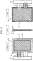
- Fig. 2 is a drawing indicating an example of a sensor device 2A according to a first embodiment, indicating an example of the outside shape of the sensor device 2A when viewed from directions toward the front, side, and back.
- the sensor device 2A indicated in Fig. 2 has conductive fabrics 21 and 22 forming electrodes, an insulative non-woven fabric 31, and a substrate 10.
- Examples of the conductive fabrics 21 and 22 include a fabric that is formed from chemical fibers such as polyester fibers, the surface of which is coated with a metal (conductor) such as copper or nickel, and a fabric that is formed from a fabric material including a conductive material (such as carbon).
- conductive fabrics 23 to 27 in embodiments described later are also formed from a material similar to the material for the conductive fabrics 21 and 22.
- the non-woven fabric 31 is a sheet-like member with insulative fibers intertwined and spread like a plane.
- the non-woven fabric 31 is formed from, for example, synthetic fibers such as polyester fibers or polyimide fibers or inorganic fibers such as glass fibers.
- non-woven fabrics 33 to 37 in embodiments described later are also formed from materials similar to the material for the non-woven fabric 31.
- the two conductive fabrics 21 and 22 face each other with the non-woven fabric 31 located in between.
- the conductive fabric 21 is joined to the surface of the non-woven fabric 31 on the front side
- the conductive fabric 22 is joined to the surface of the non-woven fabric 31 on the back side.
- the joining of the conductive fabrics 21 and 22 to the non-woven fabric 31 is performed by, for example, fusion or seaming.
- Joining by fusion is performed by, for example, applying heat or vibration to a place of joining or illuminating the place with a laser beam, in a state in which the conductive fabrics 21 and 22 and non-woven fabric 31 are overlaid on each other.
- joining by seaming is performed by sewing both by using an insulative thread such as, for example, a synthetic fiber.
- the overlaid portion between the conductive fabric 21 and the conductive fabric 22 is included inside the outer edges of the conductive fabric 22 in a plan view of the sensor device 2A. That is, the conductive fabric 21 as a whole is smaller than the conductive fabric 22, and most of the conductive fabric 21 is included in the area of the conductive fabric 22 in a plan view.
- the joining place P2 between the conductive fabric 22 and the non-woven fabric 31 partially encloses the circumference of the conductive fabric 21 in a plan view.
- the outer edges of the conductive fabric 21 and the outer edges of the conductive fabric 22 are separated from each other with part of at least one surface (surface on the front side or surface on the back side) of the non-woven fabric 31 interposed, in a plan view of the sensor device 2A. That is, the outer edges of the conductive fabric 21 and the outer edges of the conductive fabric 22 are distant from each other in a direction along the surface of the non-woven fabric 31.
- the substrate 10 includes an electronic circuit connected to the two conductive fabrics 21 and 22.
- This electronic circuit includes an amplifier circuit and the like.
- the amplifier circuit uses one electrode (conductive fabric 21, for example) as a detection electrode and amplifies an electric signal entered due to capacitive coupling between the detection electrode and a live body.
- the other electrode conductive fabric 22, for example
- the electronic circuit of the substrate 10 may be a circuit that detects a change in capacitance (mutual capacitance) formed by the two electrodes (conductive fabrics 21 and 22). In this case, the electronic circuit detects a minute motion, of the live body, corresponding to the change in capacitance.
- the conductive fabrics 21 and 22 are connected to wiring patterns on the substrate 10 by, for example, soldering.
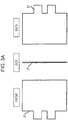
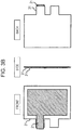
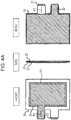
- Fig. 3A to Fig. 3C and Fig. 4A and Fig. 4B are drawings used to describe an example of a method of manufacturing the sensor device 2A indicated in Fig. 2 .
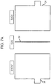
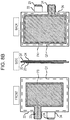
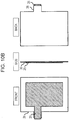
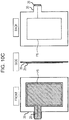
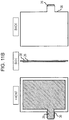
- Fig. 3A indicates a state in which nothing is attached to the non-woven fabric 31.
- the conductive fabric 21 is disposed on the surface of the non-woven fabric 31 on the front side as indicated in Fig. 3B , and the non-woven fabric 31 and conductive fabric 21 are joined together by at least one of fusion and seaming as indicated in Fig. 3C .
- the conductive fabric 22 is disposed on the surface of the non-woven fabric 31 on the back side as indicated in Fig. 4A , and the non-woven fabric 31 and conductive fabric 22 are joined together by at least one of fusion and seaming as indicated in Fig. 4B .
- a place is selected where the place does not overlay the joining place P1 between the non-woven fabric 31 and the conductive fabric 21 and where the conductive fabric 21 is not located.
- electrodes are formed by the conductive fabrics 21 and 22, and the conductive fabrics 21 and 22 are joined to the surfaces of the insulative non-woven fabric 31 on the front side and back side, one on each surface. Therefore, air permeability and flexibility can be assured. Also, the conductive fabrics 21 and 22 and the non-woven fabric 31 are joined together by at least one of fusion and seaming, making it difficult for air permeability or flexibility to be impaired. Furthermore, since the non-woven fabric 31 does not easily cause a ravel as in a woven fabric and knitted fabric, it is possible to effectively suppress a decrease in the insulation property of the conductive fabrics 21 and 22 forming electrodes.
- the porosity (density of clearances) of the non-woven fabric 31 is easily adjusted when compared with woven work and knitted work, a tradeoff between air permeability and the insulation property can be appropriately set depending on the use situation or the like.
- the conductive fabrics 21 and 22 can be stably insulated from each other.
- the outer edges of the conductive fabric 21 and the outer edges of the conductive fabric 22 are distant from each other in a direction along a surface (surface on the front side or surface on the back side) of the non-woven fabric 31. Therefore, the conductive fabrics 21 and 22 can be more stably insulated from each other.
- Fig. 5 is a drawing indicating an example of a sensor device 2B according to a second embodiment.
- the sensor device 2B indicated in Fig. 5 has conductive fabrics 23 and 24 forming electrodes, insulative non-woven fabrics 33 and 34, and the substrate 10.
- the substrate 10 in the sensor device 2B is the same as the substrate 10 in the sensor device 2A already described. This is also true for the substrate 10 in sensor devices 2C and 2D described later. Differences from the sensor device 2A already described will be mainly described below.
- the two conductive fabrics 23 and 24 face each other with the overlaid non-woven fabrics 33 and 34 located in between.
- the conductive fabric 23 is joined to the surface of the non-woven fabric 33 on the front side
- the conductive fabric 24 is joined to the surface of the non-woven fabric 34 on the back side.
- "P3" indicates a place of joining between the conductive fabric 23 and the non-woven fabric 33
- "P4" indicates a place of joining between the conductive fabric 24 and the non-woven fabric 34.
- the surface of the non-woven fabric 33 on the back side is overlaid on the surface of the non-woven fabric 34 on the front side.
- "Q1" indicates a place of joining between the non-woven fabric 33 and the non-woven fabric 34.
- the joining place Q1 between the non-woven fabric 33 to which the conductive fabric 23 is joined and the non-woven fabric 34 to which the conductive fabric 24 is joined is positioned outside the areas of the conductive fabrics 23 and 24 in a plan view of the sensor device 2B.
- joining between the conductive fabric (23 or 24) and the non-woven fabric (33 or 34) and joining between the non-woven fabrics (33 and 34) are performed by fusion or seaming as with the sensor device 2A already described.
- the outer edges of the conductive fabric 23 and the outer edges of the conductive fabric 24 are separated from each other with part of at least one surface of the non-woven fabrics 33 and 34 (surface of the non-woven fabric 33 on the front side or surface of the non-woven fabric 34 on the back side) interposed, in a plan view of the sensor device 2B. That is, the outer edges of the conductive fabric 23 and the outer edges of the conductive fabric 24 are distant from each other in a direction along the surfaces of the non-woven fabrics 33 and 34.
- Fig. 6A to Fig. 6C , Fig. 7A to Fig. 7C , and Fig. 8A and Fig. 8B are drawings used to describe an example of a method of manufacturing the sensor device 2B indicated in Fig. 5 .
- Fig. 6A indicates a state in which nothing is attached to the non-woven fabric 33.
- the conductive fabric 23 is disposed on the surface of the non-woven fabric 33 on the front side as indicated in Fig. 6B , and the non-woven fabric 33 and conductive fabric 23 are joined together by at least one of fusion and seaming as indicated in Fig. 6C .
- Fig. 7A indicates a state in which nothing is attached to the non-woven fabric 34.
- the conductive fabric 24 is disposed on the surface of the non-woven fabric 34 on the back side as indicated in Fig. 7B , and the non-woven fabric 34 and conductive fabric 24 are joined together by at least one of fusion and seaming as indicated in Fig. 7C .
- the surface on the back side of the non-woven fabric 33 in the state indicated in Fig. 6C and the surface on the front side of the non-woven fabric 34 in the state indicated in Fig. 7C are overlaid on each other as indicated in Fig. 8A .
- the non-woven fabric 33 and non-woven fabric 34 are placed in the overlaid state as indicated in Fig. 8A
- the two conductive fabrics 23 and 24 face each other with the non-woven fabrics 33 and 34 located in between.
- the non-woven fabrics 33 and 34 placed in the overlaid state are joined together by at least one of fusion and seaming as indicated in Fig. 8B .
- the non-woven fabrics 33 and 34 are joined together at positions outside the areas of the two conductive fabrics 23 and 24 in a plan view of the sensor device 2B.
- the two opposing conductive fabrics 23 and 24 are separated from each other by the overlaid non-woven fabrics 33 and 34. Therefore, the two conductive fabrics 23 and 24 can be stably insulated from each other.
- the non-woven fabric 33 to which the conductive fabric 23 on one side is joined and the non-woven fabric 34 to which the conductive fabric 24 on the other side is joined are joined together by at least one of fusion and seaming.
- Manufacturing processes can be simplified by joining the non-woven fabrics (33 and 34) together by a means similar to the means of joining the conductive fabric (23 or 24) and the non-woven fabric (33 or 34) together.
- the non-woven fabric 33 to which the conductive fabric 23 is joined and the non-woven fabric 34 to which the conductive fabric 24 is joined are joined together outside the areas of the conductive fabrics 23 and 24 in a plan view of the sensor device 2B. Therefore, the conductive fabrics 23 and 24 can be stably insulated from each other.
- the conductive fabrics 23 and 24 can be stably insulated from each other.
- the outer edges of the conductive fabric 23 and the outer edges of the conductive fabric 24 are distant from each other in a direction along the surface of the non-woven fabric 33 on the front side and the surface of the non-woven fabric 34 on the back side. Therefore, the conductive fabrics 23 and 24 can be stably insulated from each other.
- the structure, other than the above, of the sensor device 2B according to this embodiment is similar to the structure of the sensor device 2A already described, and the sensor device 2B has an effect similar to the effect of the sensor device 2A.
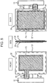
- Fig. 9 is a drawing indicating an example of a sensor device 2C according to a third embodiment.
- the sensor device 2C indicated in Fig. 9 has conductive fabrics 25 and 26 forming electrodes, insulative non-woven fabrics 35 and 36, and the substrate 10. Differences from the sensor devices 2A and 2B already described will be mainly described below.
- the two conductive fabrics 25 and 26 face each other with the non-woven fabric 35 located in between, and the two non-woven fabrics 35 and 36 face each other.
- the conductive fabric 25 is joined to the surface of the non-woven fabric 35 on the front side
- the conductive fabric 26 is joined to the surface of the non-woven fabric 36 on the front side.
- "P5" indicates a place of joining between the conductive fabric 25 and the non-woven fabric 35
- "P6" indicates a place of joining between the conductive fabric 26 and the non-woven fabric 36.
- the surface of the non-woven fabric 35 on the back side is overlaid on the surface of the non-woven fabric 36 on the front side, the conductive fabric 26 being joined to the surface of the non-woven fabric 36 on the front side.
- "Q2" indicates a place of joining between the non-woven fabric 35 and the non-woven fabric 36.
- the joining place Q2 between the non-woven fabric 35 to which the conductive fabric 25 is joined and the non-woven fabric 36 to which the conductive fabric 26 is joined is positioned outside the areas of the conductive fabrics 25 and 26 in a plan view of the sensor device 2C.
- joining between the conductive fabric (25 or 26) and the non-woven fabric (35 or 36) and joining between the non-woven fabrics (35 and 36) are performed by fusion or seaming as with the sensor devices 2A and 2B already described.
- the conductive fabrics 25 and 26 as a whole are smaller than the non-woven fabric 35 in a plan view of the sensor device 2C, and most of the conductive fabrics 25 and 26 are included in the area of the non-woven fabric 35 in a plan view. Also, the outer edges of the conductive fabric 25 and the outer edges of the conductive fabric 26 are separated from each other with part of at least one surface (surface on the front side or surface on the back side) of the non-woven fabric 35 interposed, in a plan view of the sensor device 2C. That is, the outer edges of the conductive fabric 25 and the outer edges of the conductive fabric 26 are distant from each other in a direction along the surface of the non-woven fabric 35.
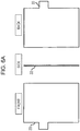
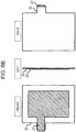
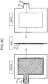
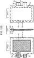
- Fig. 10A to Fig. 10C , Fig. 11A to Fig. 11C , and Fig. 12A and Fig. 12B are drawings used to describe an example of a method of manufacturing the sensor device 2C indicated in Fig. 9 .
- Fig. 10A indicates a state in which nothing is attached to the non-woven fabric 35.
- the conductive fabric 25 is disposed on the surface of the non-woven fabric 35 on the front side as indicated in Fig. 10B , and the non-woven fabric 35 and conductive fabric 25 are joined together by at least one of fusion and seaming as indicated in Fig. 10C .
- Fig. 11A indicates a state in which nothing is attached to the non-woven fabric 36.
- the conductive fabric 26 is disposed on the surface of the non-woven fabric 36 on the front side as indicated in Fig. 11B , and the non-woven fabric 36 and conductive fabric 26 are joined together by at least one of fusion and seaming as indicated in Fig. 11C .
- the surface on the back side of the non-woven fabric 35 in the state indicated in Fig. 10C , and the surface on the front side of the non-woven fabric 36 in the state indicated in Fig. 11C are overlaid on each other as indicated in Fig. 12A .
- the non-woven fabric 35 and non-woven fabric 36 are placed in the overlaid state as indicated in Fig. 12A , the two conductive fabrics 25 and 26 face each other with the non-woven fabric 35 located in between.
- the conductive fabric 26 is in a state in which both surfaces of the conductive fabric 26 are covered by the two non-woven fabrics 35 and 36.
- the non-woven fabrics 35 and 36 placed in the overlaid state are joined together by at least one of fusion and seaming as indicated in Fig. 12B .
- the non-woven fabrics 35 and 36 are joined together at positions outside the areas of the two conductive fabrics 25 and 26 in a plan view of the sensor device 2C.
- the two opposing conductive fabrics 25 and 26 are separated from each other by the non-woven fabric 35. Therefore, the two conductive fabrics 25 and 26 can be stably insulated from each other. Also, since the conductive fabric 26 is interposed between the two non-woven fabrics 35 and 36, the insulation property for the conductive fabric 26 can be enhanced.
- the structure, other than the above, of the sensor device 2C according to this embodiment is similar to the structures of the sensor devices 2A and 2B already described, and the sensor device 2C has an effect similar to the effect of the sensor devices 2A and 2B.
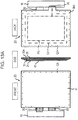
- Fig. 13A is a drawing indicating an example of a sensor device 2D according to a fourth embodiment.
- Fig. 13B is a drawing indicating the sensor device 2D indicated in Fig. 13A , in a state in which an electrode cover 41 is not illustrated.
- the surface, of the conductive fabric 25, exposed to the outside in the already-described sensor device 2C indicated in Fig. 9 (the surface is opposite to the surface in contact with the non-woven fabric 35) is covered with the insulative electrode cover 41.
- the other structure is almost the same as in the sensor device 2C indicated in Fig. 9 .
- the non-woven fabric 36 in the sensor device 2C is replaced with a non-woven fabric 36A, which is slightly larger in size than the non-woven fabric 36.
- the electrode cover 41 is formed from an insulative non-woven fabric and is joined to the non-woven fabric 36A by fusion or seaming.
- "Q3" in Fig. 13A indicates a place where the electrode cover 41 and non-woven fabric 36A are joined together. As indicated in Fig. 13A , the joining place Q3 between the electrode cover 41 and the non-woven fabric 36A is positioned outside the areas of the conductive fabric 25 and conductive fabric 26.
- the insulation property for the conductive fabric 25 can be enhanced. Also, manufacturing processes can be simplified by joining the non-woven fabric 36A and electrode cover 41 together by a means similar to the means of joining the conductive fabric (25 or 26) and the non-woven fabric (35 or 36A).
- the sensor device 2D when the sensor device 2D is disposed inside the vehicle seat 1 ( Fig. 1 ), the sensor device 2D may be disposed so that the electrode cover 41 faces the outside of the vehicle seat 1 and the electrode cover 41 may have the same color as the outer surface of the vehicle seat 1.
- the conductive fabric 25 is covered with the electrode cover 41 that faces the outside of the vehicle seat 1 and that has the same color as the outer surface of the vehicle seat 1, it is possible to make the conductive fabric 25 less likely to be noticeable from the outside and to make the electrode cover 41 itself less likely to be noticeable.
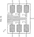
- Fig. 14 is a drawing indicating a variation of a sensor device according to an embodiment of the present invention.
- a sensor device 2E indicated in Fig. 14 has an insulative non-woven fabric 37 and a plurality of conductive fabrics 27A to 27F joined to one surface of the non-woven fabric 37 by fusion or seaming.
- the wiring patterns 51A to 51F are formed on the surface of the non-woven fabric 37 by, for example, a film forming method such as sputtering.
- the conductive fabrics 27A to 27D and the wiring patterns 51A to 51F formed on the surface of the non-woven fabric 37 in advance electrically continuous to each other in this way it is unnecessary to connect these conductive fabrics to other wires such as electronic circuits by using connectors. Therefore, assembling processes can be simplified and the number of parts can be reduced. Also, since positions at which to dispose the conductive fabrics 27A to 27D on the surface of the non-woven fabric 37 are clear, work to position the conductive fabrics 27A to 27D is easy and the efficiency of manufacturing can be improved.
- sensor devices 2 may be disposed, for example, inside the lining (interior cover) of a vehicle.
- lining internal cover
- sensor devices 2 may be disposed, for example, inside the lining (interior cover) of a vehicle.
- an electrode cover that faces the outer surface side of the lining and has the same color as the outer surface of the lining, it is possible to make the conductive fabric covered with the electrode cover and the electrode cover itself less likely to be noticeable from the outside.
- the number of conductive fabrics attached to each surface of the non-woven fabric may be plural.
- the number of conductive fabrics on the front side of the non-woven fabric and the number of conductive fabrics on the back side may be the same or may be different.
Landscapes
- Engineering & Computer Science (AREA)
- Life Sciences & Earth Sciences (AREA)
- Health & Medical Sciences (AREA)
- Textile Engineering (AREA)
- Pathology (AREA)
- Medical Informatics (AREA)
- Physics & Mathematics (AREA)
- Veterinary Medicine (AREA)
- Public Health (AREA)
- Biophysics (AREA)
- General Health & Medical Sciences (AREA)
- Biomedical Technology (AREA)
- Heart & Thoracic Surgery (AREA)
- Mechanical Engineering (AREA)
- Molecular Biology (AREA)
- Surgery (AREA)
- Animal Behavior & Ethology (AREA)
- Aviation & Aerospace Engineering (AREA)
- Transportation (AREA)
- Computer Networks & Wireless Communication (AREA)
- Seats For Vehicles (AREA)
- Measurement Of The Respiration, Hearing Ability, Form, And Blood Characteristics Of Living Organisms (AREA)
- Measurement And Recording Of Electrical Phenomena And Electrical Characteristics Of The Living Body (AREA)
Abstract
Description
- One aspect of the present disclosure relates to a sensor device, a manufacturing method thereof, and a vehicle seat equipped with a sensor device.
- A device is known that contactlessly detects a motion or electric phenomenon of a live body by using an electrode disposed near the live body. In
PTL 1, for example, an electrode device is described that is disposed at a vehicle seat or the like and performs electrocardiogram measurement. - PTL 1: Japanese Unexamined Patent Application Publication No.
2013-188277 - In the electrode device described in
PTL 1, an electrode and insulating body are formed from a woven fabric or knitted fabric having stretchability and air permeability to suppress a feeling of discomfort in touch and a feeling of stuffiness in a case in which the electrode device is used at a vehicle seat or the like. - However, when the insulating body is formed from a woven fabric or knitted fabric, if a ravel occurs in part of the fabric, the ravel easily expand to the periphery thereof. Since the insulation property decreases at the raveled portion, there is the possibility that a problem occurs in detection performance.
- Accordingly, an object of one aspect of the present disclosure is to provide a sensor device that can suppress a decrease in an insulation property for electrodes while maintaining air permeability and flexibility, a method of manufacturing the sensor device, and a vehicle seat using such sensor devices.
- According to one aspect of the present disclosure, a sensor device that has an insulative non-woven fabric and a conductive fabric forming an electrode is provided. The conductive fabric is joined to one surface of the non-woven fabric by at least one of fusion and seaming.
- According to one aspect of the present disclosure, it is possible to provide a sensor device that can suppress a decrease in an insulation property for electrodes while maintaining air permeability and flexibility, a method of manufacturing the sensor device, and a vehicle seat using such sensor devices.
-
- [
Fig. 1] Fig. 1 is a drawing indicating an example of a vehicle seat equipped with sensor devices according to the embodiment. - [
Fig. 2] Fig. 2 is a drawing indicating an example of a sensor device according to a first embodiment. - [
Fig. 3A] Fig. 3A is a drawing used to describe an example of a method of manufacturing the sensor device indicated inFig. 2 . - [
Fig. 3B] Fig. 3B is a drawing used to describe the example of the method of manufacturing the sensor device indicated inFig. 2 . - [
Fig. 3C] Fig. 3C is a drawing used to describe the example of the method of manufacturing the sensor device indicated inFig. 2 . - [
Fig. 4A] Fig. 4A is a drawing used to describe the example of the method of manufacturing the sensor device indicated inFig. 2 . - [
Fig. 4B] Fig. 4B is a drawing used to describe the example of the method of manufacturing the sensor device indicated inFig. 2 . - [
Fig. 5] Fig. 5 is a drawing indicating an example of a sensor device according to a second embodiment. - [
Fig. 6A] Fig. 6A is a drawing used to describe an example of a method of manufacturing the sensor device indicated inFig. 5 . - [
Fig. 6B] Fig. 6B is a drawing used to describe the example of the method of manufacturing the sensor device indicated inFig. 5 . - [
Fig. 6C] Fig. 6C is a drawing used to describe the example of the method of manufacturing the sensor device indicated inFig. 5 . - [
Fig. 7A] Fig. 7A is a drawing used to describe the example of the method of manufacturing the sensor device indicated inFig. 5 . - [
Fig. 7B] Fig. 7B is a drawing used to describe the example of the method of manufacturing the sensor device indicated inFig. 5 . - [
Fig. 7C] Fig. 7C is a drawing used to describe the example of the method of manufacturing the sensor device indicated inFig. 5 . - [
Fig. 8A] Fig. 8A is a drawing used to describe the example of the method of manufacturing the sensor device indicated inFig. 5 . - [
Fig. 8B] Fig. 8B is a drawing used to describe the example of the method of manufacturing the sensor device indicated inFig. 5 . - [
Fig. 9] Fig. 9 is a drawing indicating an example of a sensor device according to a third embodiment. - [
Fig. 10A] Fig. 10A is a drawing used to describe an example of a method of manufacturing the sensor device indicated inFig. 9 . - [
Fig. 10B] Fig. 10B is a drawing used to describe the example of the method of manufacturing the sensor device indicated inFig. 9 . - [
Fig. 10C] Fig. 10C is a drawing used to describe the example of the method of manufacturing the sensor device indicated inFig. 9 . - [
Fig. 11A] Fig. 11A is a drawing used to describe the example of the method of manufacturing the sensor device indicated inFig. 9 . - [
Fig. 11B] Fig. 11B is a drawing used to describe the example of the method of manufacturing the sensor device indicated inFig. 9 . - [
Fig. 11C] Fig. 11C is a drawing used to describe the example of the method of manufacturing the sensor device indicated inFig. 9 . - [
Fig. 12A] Fig. 12A is a drawing used to describe the example of the method of manufacturing the sensor device indicated inFig. 9 . - [
Fig. 12B] Fig. 12B is a drawing used to describe the example of the method of manufacturing the sensor device indicated inFig. 9 . - [
Fig. 13A] Fig. 13A is a drawing indicating an example of a sensor device according to a fourth embodiment. - [
Fig. 13B] Fig. 13B is a drawing indicating the sensor device indicated inFig. 13A , in a state in which the electrode cover is not illustrated. - [
Fig. 14] Fig. 14 is a drawing indicating one variation of a sensor device. - Embodiments of the present invention will be described below with reference to the drawings.
-
Fig. 1 is a drawing indicating an example of avehicle seat 1 equipped withsensor devices 2 according to an embodiment of the present invention. In the example inFig. 1 , thevehicle seat 1 has abackrest portion 1A and aseat portion 1B. A plurality ofsensor devices 2 are disposed inside the surface of each of thebackrest portion 1A andseat portion 1B. Thevehicle seat 1 may have a function for blowing air to be used for temperature adjustment from, for example, the surface of thebackrest portion 1A orseat portion 1B. In this case, since thesensor device 2 according to this embodiment has air permeability, thesensor device 2 does not hinder a flow of air. Therefore, thesensor devices 2 can be disposed at appropriate positions in thebackrest portion 1A andseat portion 1B without affecting the temperature adjustment function, so thesensor device 2 can detect information about a live body (such as a change in the motion of the body and an electric signal generated by the live body) with good sensitivity. - The
sensor device 2 may have an electrode cover that faces the outside of thevehicle seat 1 and is made of a non-woven fabric having a color similar to the color of the outer surface of thevehicle seat 1, as will be described later. Since this electrode cover covers the electrodes (conductive fabrics), it is possible to prevent the electrodes (conductive fabrics) from being noticeable from the outside. - Sensor devices according to embodiments of the present invention will be described below.
-
Fig. 2 is a drawing indicating an example of asensor device 2A according to a first embodiment, indicating an example of the outside shape of thesensor device 2A when viewed from directions toward the front, side, and back. Thesensor device 2A indicated inFig. 2 hasconductive fabrics non-woven fabric 31, and asubstrate 10. - Examples of the
conductive fabrics conductive fabrics 23 to 27 in embodiments described later are also formed from a material similar to the material for theconductive fabrics - The
non-woven fabric 31 is a sheet-like member with insulative fibers intertwined and spread like a plane. Thenon-woven fabric 31 is formed from, for example, synthetic fibers such as polyester fibers or polyimide fibers or inorganic fibers such as glass fibers. Incidentally,non-woven fabrics 33 to 37 in embodiments described later are also formed from materials similar to the material for thenon-woven fabric 31. - The two
conductive fabrics non-woven fabric 31 located in between. Theconductive fabric 21 is joined to the surface of thenon-woven fabric 31 on the front side, and theconductive fabric 22 is joined to the surface of thenon-woven fabric 31 on the back side. The joining of theconductive fabrics non-woven fabric 31 is performed by, for example, fusion or seaming. Joining by fusion is performed by, for example, applying heat or vibration to a place of joining or illuminating the place with a laser beam, in a state in which theconductive fabrics non-woven fabric 31 are overlaid on each other. Also, joining by seaming is performed by sewing both by using an insulative thread such as, for example, a synthetic fiber. - In
Fig. 2 , "P1" indicates a place of joining between theconductive fabric 21 and thenon-woven fabric 31, and "P2" indicates a place of joining between theconductive fabric 22 and thenon-woven fabric 31. As indicated inFig. 2 , there is a displacement in a plan view of thesensor device 2A between the joining place P1, where theconductive fabric 21 is joined to thenon-woven fabric 31, and the joining place P2, where theconductive fabric 22 is joined to thenon-woven fabric 31. That is, the joining place P1 and joining place P2 are not overlaid on each other. - As indicated in
Fig. 2 , most of the overlaid portion between theconductive fabric 21 and theconductive fabric 22 is included inside the outer edges of theconductive fabric 22 in a plan view of thesensor device 2A. That is, theconductive fabric 21 as a whole is smaller than theconductive fabric 22, and most of theconductive fabric 21 is included in the area of theconductive fabric 22 in a plan view. The joining place P2 between theconductive fabric 22 and thenon-woven fabric 31 partially encloses the circumference of theconductive fabric 21 in a plan view. - Also, as illustrated in
Fig. 2 , the outer edges of theconductive fabric 21 and the outer edges of theconductive fabric 22 are separated from each other with part of at least one surface (surface on the front side or surface on the back side) of thenon-woven fabric 31 interposed, in a plan view of thesensor device 2A. That is, the outer edges of theconductive fabric 21 and the outer edges of theconductive fabric 22 are distant from each other in a direction along the surface of thenon-woven fabric 31. - The
substrate 10 includes an electronic circuit connected to the twoconductive fabrics conductive fabric 21, for example) as a detection electrode and amplifies an electric signal entered due to capacitive coupling between the detection electrode and a live body. In this case, the other electrode (conductive fabric 22, for example) functions as a shield electrode controlled so as, for example, to have the same potential as the detection electrode. Alternatively, the electronic circuit of thesubstrate 10 may be a circuit that detects a change in capacitance (mutual capacitance) formed by the two electrodes (conductive fabrics 21 and 22). In this case, the electronic circuit detects a minute motion, of the live body, corresponding to the change in capacitance. Theconductive fabrics substrate 10 by, for example, soldering. -
Fig. 3A to Fig. 3C andFig. 4A andFig. 4B are drawings used to describe an example of a method of manufacturing thesensor device 2A indicated inFig. 2 . -
Fig. 3A indicates a state in which nothing is attached to thenon-woven fabric 31. In this state inFig. 3A , theconductive fabric 21 is disposed on the surface of thenon-woven fabric 31 on the front side as indicated inFig. 3B , and thenon-woven fabric 31 andconductive fabric 21 are joined together by at least one of fusion and seaming as indicated inFig. 3C . - After that, the
conductive fabric 22 is disposed on the surface of thenon-woven fabric 31 on the back side as indicated inFig. 4A , and thenon-woven fabric 31 andconductive fabric 22 are joined together by at least one of fusion and seaming as indicated inFig. 4B . At this time, as the joining place P2 between thenon-woven fabric 31 and theconductive fabric 22, a place is selected where the place does not overlay the joining place P1 between thenon-woven fabric 31 and theconductive fabric 21 and where theconductive fabric 21 is not located. - As described above, according to the
sensor device 2A in this embodiment, electrodes are formed by theconductive fabrics conductive fabrics non-woven fabric 31 on the front side and back side, one on each surface. Therefore, air permeability and flexibility can be assured. Also, theconductive fabrics non-woven fabric 31 are joined together by at least one of fusion and seaming, making it difficult for air permeability or flexibility to be impaired. Furthermore, since thenon-woven fabric 31 does not easily cause a ravel as in a woven fabric and knitted fabric, it is possible to effectively suppress a decrease in the insulation property of theconductive fabrics non-woven fabric 31 is easily adjusted when compared with woven work and knitted work, a tradeoff between air permeability and the insulation property can be appropriately set depending on the use situation or the like. - According to the
sensor device 2A in this embodiment, there is a displacement in a plan view of thesensor device 2A between the joining place P1, where theconductive fabric 21 is joined to thenon-woven fabric 31, and the joining place P2, where theconductive fabric 22 is joined to thenon-woven fabric 31. Therefore, theconductive fabrics - According to the
sensor device 2A in this embodiment, the outer edges of theconductive fabric 21 and the outer edges of theconductive fabric 22 are distant from each other in a direction along a surface (surface on the front side or surface on the back side) of thenon-woven fabric 31. Therefore, theconductive fabrics -
Fig. 5 is a drawing indicating an example of asensor device 2B according to a second embodiment. Thesensor device 2B indicated inFig. 5 hasconductive fabrics non-woven fabrics substrate 10. Thesubstrate 10 in thesensor device 2B is the same as thesubstrate 10 in thesensor device 2A already described. This is also true for thesubstrate 10 insensor devices sensor device 2A already described will be mainly described below. - The two
conductive fabrics non-woven fabrics conductive fabric 23 is joined to the surface of thenon-woven fabric 33 on the front side, and theconductive fabric 24 is joined to the surface of thenon-woven fabric 34 on the back side. InFig. 5 , "P3" indicates a place of joining between theconductive fabric 23 and thenon-woven fabric 33, and "P4" indicates a place of joining between theconductive fabric 24 and thenon-woven fabric 34. In the example inFig. 5 , there is a displacement in a plan view of thesensor device 2B between the joining place P3, where theconductive fabric 23 is joined to thenon-woven fabric 33, and the joining place P4, where theconductive fabric 24 is joined to thenon-woven fabric 34. That is, the joining place P3 and joining place P4 are not overlaid on each other. - The surface of the
non-woven fabric 33 on the back side is overlaid on the surface of thenon-woven fabric 34 on the front side. InFig. 5 , "Q1" indicates a place of joining between thenon-woven fabric 33 and thenon-woven fabric 34. As indicated inFig. 5 , the joining place Q1 between thenon-woven fabric 33 to which theconductive fabric 23 is joined and thenon-woven fabric 34 to which theconductive fabric 24 is joined is positioned outside the areas of theconductive fabrics sensor device 2B. - Incidentally, joining between the conductive fabric (23 or 24) and the non-woven fabric (33 or 34) and joining between the non-woven fabrics (33 and 34) are performed by fusion or seaming as with the
sensor device 2A already described. - As illustrated in
Fig. 5 , the outer edges of theconductive fabric 23 and the outer edges of theconductive fabric 24 are separated from each other with part of at least one surface of thenon-woven fabrics 33 and 34 (surface of thenon-woven fabric 33 on the front side or surface of thenon-woven fabric 34 on the back side) interposed, in a plan view of thesensor device 2B. That is, the outer edges of theconductive fabric 23 and the outer edges of theconductive fabric 24 are distant from each other in a direction along the surfaces of thenon-woven fabrics -
Fig. 6A to Fig. 6C ,Fig. 7A to Fig. 7C , andFig. 8A andFig. 8B are drawings used to describe an example of a method of manufacturing thesensor device 2B indicated inFig. 5 . -
Fig. 6A indicates a state in which nothing is attached to thenon-woven fabric 33. In this state inFig. 6A , theconductive fabric 23 is disposed on the surface of thenon-woven fabric 33 on the front side as indicated inFig. 6B , and thenon-woven fabric 33 andconductive fabric 23 are joined together by at least one of fusion and seaming as indicated inFig. 6C . - Also,
Fig. 7A indicates a state in which nothing is attached to thenon-woven fabric 34. In this state inFig. 7A , theconductive fabric 24 is disposed on the surface of thenon-woven fabric 34 on the back side as indicated inFig. 7B , and thenon-woven fabric 34 andconductive fabric 24 are joined together by at least one of fusion and seaming as indicated inFig. 7C . - After that, the surface on the back side of the
non-woven fabric 33 in the state indicated inFig. 6C and the surface on the front side of thenon-woven fabric 34 in the state indicated inFig. 7C are overlaid on each other as indicated inFig. 8A . When thenon-woven fabric 33 andnon-woven fabric 34 are placed in the overlaid state as indicated inFig. 8A , the twoconductive fabrics non-woven fabrics non-woven fabrics Fig. 8B . At this time, thenon-woven fabrics conductive fabrics sensor device 2B. - As described above, according to the
sensor device 2B in this embodiment, the two opposingconductive fabrics non-woven fabrics conductive fabrics - According to the
sensor device 2B in this embodiment, thenon-woven fabric 33 to which theconductive fabric 23 on one side is joined and thenon-woven fabric 34 to which theconductive fabric 24 on the other side is joined are joined together by at least one of fusion and seaming. Manufacturing processes can be simplified by joining the non-woven fabrics (33 and 34) together by a means similar to the means of joining the conductive fabric (23 or 24) and the non-woven fabric (33 or 34) together. - According to the
sensor device 2B in this embodiment, thenon-woven fabric 33 to which theconductive fabric 23 is joined and thenon-woven fabric 34 to which theconductive fabric 24 is joined are joined together outside the areas of theconductive fabrics sensor device 2B. Therefore, theconductive fabrics - According to the
sensor device 2B in this embodiment, there is a displacement between the joining place P3, where theconductive fabric 23 is joined to thenon-woven fabric 33, and the joining place P4, where theconductive fabric 24 is joined to thenon-woven fabric 34. Therefore, theconductive fabrics - According to the
sensor device 2B in this embodiment, the outer edges of theconductive fabric 23 and the outer edges of theconductive fabric 24 are distant from each other in a direction along the surface of thenon-woven fabric 33 on the front side and the surface of thenon-woven fabric 34 on the back side. Therefore, theconductive fabrics - The structure, other than the above, of the
sensor device 2B according to this embodiment is similar to the structure of thesensor device 2A already described, and thesensor device 2B has an effect similar to the effect of thesensor device 2A. -
Fig. 9 is a drawing indicating an example of asensor device 2C according to a third embodiment. Thesensor device 2C indicated inFig. 9 hasconductive fabrics non-woven fabrics substrate 10. Differences from thesensor devices - As indicated in
Fig. 9 , the twoconductive fabrics non-woven fabric 35 located in between, and the twonon-woven fabrics conductive fabric 25 is joined to the surface of thenon-woven fabric 35 on the front side, and theconductive fabric 26 is joined to the surface of thenon-woven fabric 36 on the front side. InFig. 9 , "P5" indicates a place of joining between theconductive fabric 25 and thenon-woven fabric 35, and "P6" indicates a place of joining between theconductive fabric 26 and thenon-woven fabric 36. In the example inFig. 9 , there is a displacement in a plan view of thesensor device 2C between the joining place P5, where theconductive fabric 25 is joined to thenon-woven fabric 35, and the joining place P6, where theconductive fabric 26 is joined to thenon-woven fabric 36. That is, the joining place P5 and joining place P6 are not overlaid on each other. - The surface of the
non-woven fabric 35 on the back side is overlaid on the surface of thenon-woven fabric 36 on the front side, theconductive fabric 26 being joined to the surface of thenon-woven fabric 36 on the front side. InFig. 9 , "Q2" indicates a place of joining between thenon-woven fabric 35 and thenon-woven fabric 36. As indicated inFig. 9 , the joining place Q2 between thenon-woven fabric 35 to which theconductive fabric 25 is joined and thenon-woven fabric 36 to which theconductive fabric 26 is joined is positioned outside the areas of theconductive fabrics sensor device 2C. - Incidentally, joining between the conductive fabric (25 or 26) and the non-woven fabric (35 or 36) and joining between the non-woven fabrics (35 and 36) are performed by fusion or seaming as with the
sensor devices - As indicated in
Fig. 9 , theconductive fabrics non-woven fabric 35 in a plan view of thesensor device 2C, and most of theconductive fabrics non-woven fabric 35 in a plan view. Also, the outer edges of theconductive fabric 25 and the outer edges of theconductive fabric 26 are separated from each other with part of at least one surface (surface on the front side or surface on the back side) of thenon-woven fabric 35 interposed, in a plan view of thesensor device 2C. That is, the outer edges of theconductive fabric 25 and the outer edges of theconductive fabric 26 are distant from each other in a direction along the surface of thenon-woven fabric 35. -
Fig. 10A to Fig. 10C ,Fig. 11A to Fig. 11C , andFig. 12A andFig. 12B are drawings used to describe an example of a method of manufacturing thesensor device 2C indicated inFig. 9 . -
Fig. 10A indicates a state in which nothing is attached to thenon-woven fabric 35. In this state inFig. 10A , theconductive fabric 25 is disposed on the surface of thenon-woven fabric 35 on the front side as indicated inFig. 10B , and thenon-woven fabric 35 andconductive fabric 25 are joined together by at least one of fusion and seaming as indicated inFig. 10C . - Also,
Fig. 11A indicates a state in which nothing is attached to thenon-woven fabric 36. In this state inFig. 11A , theconductive fabric 26 is disposed on the surface of thenon-woven fabric 36 on the front side as indicated inFig. 11B , and thenon-woven fabric 36 andconductive fabric 26 are joined together by at least one of fusion and seaming as indicated inFig. 11C . - After that, the surface on the back side of the
non-woven fabric 35 in the state indicated inFig. 10C , and the surface on the front side of thenon-woven fabric 36 in the state indicated inFig. 11C are overlaid on each other as indicated inFig. 12A . When thenon-woven fabric 35 andnon-woven fabric 36 are placed in the overlaid state as indicated inFig. 12A , the twoconductive fabrics non-woven fabric 35 located in between. Also, theconductive fabric 26 is in a state in which both surfaces of theconductive fabric 26 are covered by the twonon-woven fabrics non-woven fabrics Fig. 12B . At this time, thenon-woven fabrics conductive fabrics sensor device 2C. - As described above, according to the
sensor device 2C in this embodiment, the two opposingconductive fabrics non-woven fabric 35. Therefore, the twoconductive fabrics conductive fabric 26 is interposed between the twonon-woven fabrics conductive fabric 26 can be enhanced. - The structure, other than the above, of the
sensor device 2C according to this embodiment is similar to the structures of thesensor devices sensor device 2C has an effect similar to the effect of thesensor devices -
Fig. 13A is a drawing indicating an example of asensor device 2D according to a fourth embodiment.Fig. 13B is a drawing indicating thesensor device 2D indicated inFig. 13A , in a state in which anelectrode cover 41 is not illustrated. In thesensor device 2D, the surface, of theconductive fabric 25, exposed to the outside in the already-describedsensor device 2C indicated inFig. 9 (the surface is opposite to the surface in contact with the non-woven fabric 35) is covered with theinsulative electrode cover 41. The other structure is almost the same as in thesensor device 2C indicated inFig. 9 . In thesensor device 2D, however, thenon-woven fabric 36 in thesensor device 2C is replaced with anon-woven fabric 36A, which is slightly larger in size than thenon-woven fabric 36. - The
electrode cover 41 is formed from an insulative non-woven fabric and is joined to thenon-woven fabric 36A by fusion or seaming. "Q3" inFig. 13A indicates a place where theelectrode cover 41 andnon-woven fabric 36A are joined together. As indicated inFig. 13A , the joining place Q3 between theelectrode cover 41 and thenon-woven fabric 36A is positioned outside the areas of theconductive fabric 25 andconductive fabric 26. - Since, in the
sensor device 2D according to this embodiment, the surface, exposed to the outside, of theconductive fabric 25 is covered with theelectrode cover 41 formed from an insulative non-woven fabric as described above, the insulation property for theconductive fabric 25 can be enhanced. Also, manufacturing processes can be simplified by joining thenon-woven fabric 36A and electrode cover 41 together by a means similar to the means of joining the conductive fabric (25 or 26) and the non-woven fabric (35 or 36A). - Incidentally, when the
sensor device 2D is disposed inside the vehicle seat 1 (Fig. 1 ), thesensor device 2D may be disposed so that theelectrode cover 41 faces the outside of thevehicle seat 1 and theelectrode cover 41 may have the same color as the outer surface of thevehicle seat 1. Thus, since theconductive fabric 25 is covered with theelectrode cover 41 that faces the outside of thevehicle seat 1 and that has the same color as the outer surface of thevehicle seat 1, it is possible to make theconductive fabric 25 less likely to be noticeable from the outside and to make theelectrode cover 41 itself less likely to be noticeable. - So far, sensor devices according to embodiments of the present invention have been described. However, the present invention is not limited only to the embodiments described above but various variations and modifications are possible without departing from the scope of the present invention.
-
Fig. 14 is a drawing indicating a variation of a sensor device according to an embodiment of the present invention. - A
sensor device 2E indicated inFig. 14 has an insulativenon-woven fabric 37 and a plurality ofconductive fabrics 27A to 27F joined to one surface of thenon-woven fabric 37 by fusion or seaming. On the surface of thenon-woven fabric 37, to which theconductive fabrics 27A to 27D are joined,wiring patterns 51A to 51F electrically continuous to theconductive fabrics 27A to 27D are formed in advance. Thewiring patterns 51A to 51F are formed on the surface of thenon-woven fabric 37 by, for example, a film forming method such as sputtering. By making theconductive fabrics 27A to 27D and thewiring patterns 51A to 51F formed on the surface of thenon-woven fabric 37 in advance electrically continuous to each other in this way, it is unnecessary to connect these conductive fabrics to other wires such as electronic circuits by using connectors. Therefore, assembling processes can be simplified and the number of parts can be reduced. Also, since positions at which to dispose theconductive fabrics 27A to 27D on the surface of thenon-woven fabric 37 are clear, work to position theconductive fabrics 27A to 27D is easy and the efficiency of manufacturing can be improved. - Although, in
Fig. 1 , an example in whichsensor devices 2 are disposed inside thevehicle seat 1 is indicated, the present invention is not limited to this. In another example of the present invention,sensor devices 2 may be disposed, for example, inside the lining (interior cover) of a vehicle. In this case, by using an electrode cover that faces the outer surface side of the lining and has the same color as the outer surface of the lining, it is possible to make the conductive fabric covered with the electrode cover and the electrode cover itself less likely to be noticeable from the outside. - In the first to fourth embodiments described above, an example is taken in which one conductive fabric is attached to each of the front side and back side of a non-woven fabric. However, the number of conductive fabrics attached to each surface of the non-woven fabric may be plural. Also, the number of conductive fabrics on the front side of the non-woven fabric and the number of conductive fabrics on the back side may be the same or may be different.
- The shapes and sizes of the conductive fabrics and non-woven fabrics and their positional relationships taken as examples in the first to fourth embodiments described above are merely examples, and may be appropriately changed.
- This application claims priority based on Japanese Patent Application No.
2017-241148 filed on December 15, 2017 -
- 1
- vehicle seat
- 1A
- backrest portion
- 1B
- seat portion
- 2, 2A to 2E
- sensor device
- 10
- substrate
- 21 to 26, 27A to 27F
- conductive fabric
- 31, 33 to 37
- non-woven fabric
- 41
- electrode cover
- 51A to 51F
- wiring pattern
- P1 to P6, Q1 to Q3
- joining place
Claims (15)
- A sensor device comprising:a conductive fabric forming an electrode; andan insulative non-woven fabric, whereinthe conductive fabric is joined to one surface of the non-woven fabric by at least one of fusion and seaming.
- The sensor device according to Claim 1, further comprising a second conductive fabric facing the conductive fabric, which is a first conductive fabric, with the insulative non-woven fabric located in between, wherein
the first conductive fabric is joined to the one surface of the non-woven fabric by at least one of fusion and seaming, and
the second conductive fabric is joined to another surface of the non-woven fabric by at least one of fusion and seaming. - The sensor device according to Claim 1, further comprising:a second non-woven fabric overlaid on the non-woven fabric, which is a first non-woven fabric; anda second conductive fabric facing the conductive fabric, which is a first conductive fabric, with the first non-woven fabric and the second non-woven fabric located in between, whereinthe first conductive fabric is joined to the one surface of the first non-woven fabric adjacent to the first conductive fabric by at least one of fusion and seaming, andthe second conductive fabric is joined to one surface of the second non-woven fabric adjacent to the second conductive fabric by at least one of fusion and seaming.
- The sensor device according to Claim 1, further comprising:a second non-woven fabric facing the non-woven fabric, which is a first non-woven fabric; anda second conductive fabric facing the conductive fabric, which is the first conductive fabric, with the first non-woven fabric located in between, whereinthe first conductive fabric is joined to the one surface of the first non-woven fabric by at least one of fusion and seaming, andthe second conductive fabric is joined to one surface of the second non-woven fabric by at least one of fusion and seaming.
- The sensor device according to Claim 3 or 4, wherein the first non-woven fabric to which the first conductive fabric is joined and the second non-woven fabric to which the second conductive fabric is joined are joined together by at least one of fusion and seaming.
- The sensor device according to Claim 5, wherein a joining place between the first non-woven fabric to which the first conductive fabric is joined and the second non-woven fabric to which the second conductive fabric is joined is positioned outside areas of the first and second conductive fabrics in a plan view of the sensor device.
- The sensor device according to any one of Claims 2 to 6, wherein there is a displacement in a plan view of the sensor device between a place where the first conductive fabric is joined to the non-woven fabric and a place where the second conductive fabric is joined to the non-woven fabric.
- The sensor device according to any one of Claims 2 to 7, wherein an outer edge of the first conductive fabric and an outer edge of the second conductive fabric are distant from each other in a direction along the one surface of the non-woven fabric.
- The sensor device according to any one of Claims 1 to 8, wherein, on the one surface of the non-woven fabric, a wiring pattern electrically continuous to the conductive fabric joined to the one surface is formed.
- The sensor device according to any one of Claims 1 to 9, further comprising an electrode cover that covers an opposite surface to a surface of the conductive fabric in contact with the non-woven fabric, wherein
the electrode cover is formed from an insulative non-woven fabric, and
the electrode cover and the non-woven fabric to which the conductive fabric is joined are joined together by at least one of fusion and seaming. - The sensor device according to Claim 10, wherein:the sensor device is disposed inside a vehicle seat or inside a lining of a vehicle so that the electrode cover faces an outside of the vehicle seat or an outside of the lining, anda color of the electrode cover is the same as a color of an outer surface of the vehicle seat or a color of an outer surface of the lining.
- A method of manufacturing a sensor device that has first and second conductive fabrics forming electrodes and has an insulative non-woven fabric mutually insulating the first and second conductive fabrics, the method comprising:joining the first conductive fabric to one surface of the non-woven fabric by at least one of fusion and seaming; andjoining the second conductive fabric to another surface of the non-woven fabric by at least one of fusion and seaming, whereinthe second conductive fabric is joined to the non-woven fabric in a place displaced from a place where the first conductive fabric is joined to the non-woven fabric in a plan view of the sensor device.
- A method of manufacturing a sensor device that has first and second conductive fabrics forming electrodes and has first and second non-woven fabrics, which are insulative and overlaid, the method comprising:joining the first conductive fabric to one surface of the first non-woven fabric by at least one of fusion and seaming;joining the second conductive fabric to one surface of the second non-woven fabric by at least one of fusion and seaming; andjoining the first non-woven fabric to which the first conductive fabric is joined and the second non-woven fabric to which the second conductive fabric is joined together by at least one of fusion and seaming, the first and second non-woven fabrics being overlaid on each other so that the first and second conductive fabrics face each other with the first and second non-woven fabrics located in between, whereinthe first non-woven fabric and the second non-woven fabric are joined together at a position outside areas of the first and second conductive fabrics in a plan view of the sensor device.
- A method of manufacturing a sensor device that has first and second conductive fabrics forming electrodes and has first and second non-woven fabrics, which are insulative, the method comprising:joining the first conductive fabric to one surface of the first non-woven fabric by at least one of fusion and seaming;joining the second conductive fabric to one surface of the second non-woven fabric by at least one of fusion and seaming; andjoining the first non-woven fabric to which the first conductive fabric is joined and the second non-woven fabric to which the second conductive fabric is joined together by at least one of fusion and seaming, the first and second non-woven fabrics being overlaid on each other so that the first and second conductive fabrics face each other with the first non-woven fabric located in between, whereinthe first non-woven fabric and second non-woven fabric are joined together at a position outside areas of the first and second conductive fabrics in a plan view of the sensor device.
- A vehicle seat inside which the sensor device according to any one of Claims 1 to 10 is disposed.
Applications Claiming Priority (2)
| Application Number | Priority Date | Filing Date | Title |
|---|---|---|---|
| JP2017241148 | 2017-12-15 | ||
| PCT/JP2018/044077 WO2019116919A1 (en) | 2017-12-15 | 2018-11-29 | Sensor device, production method therefor, and vehicle seat |
Publications (3)
| Publication Number | Publication Date |
|---|---|
| EP3725218A1 true EP3725218A1 (en) | 2020-10-21 |
| EP3725218A4 EP3725218A4 (en) | 2022-01-19 |
| EP3725218B1 EP3725218B1 (en) | 2023-06-07 |
Family
ID=66819280
Family Applications (1)
| Application Number | Title | Priority Date | Filing Date |
|---|---|---|---|
| EP18888755.8A Active EP3725218B1 (en) | 2017-12-15 | 2018-11-29 | Sensor device, production method therefor, and vehicle seat |
Country Status (5)
| Country | Link |
|---|---|
| US (1) | US11794448B2 (en) |
| EP (1) | EP3725218B1 (en) |
| JP (1) | JP6818163B2 (en) |
| CN (1) | CN111542264B (en) |
| WO (1) | WO2019116919A1 (en) |
Families Citing this family (3)
| Publication number | Priority date | Publication date | Assignee | Title |
|---|---|---|---|---|
| WO2021049071A1 (en) * | 2019-09-12 | 2021-03-18 | アルプスアルパイン株式会社 | Sensor device and seat for vehicle |
| JP7517676B2 (en) * | 2020-02-27 | 2024-07-17 | 株式会社国際電気通信基礎技術研究所 | Cloth-type sensor, clothing-type sensor, and robot equipped with clothing-type sensor |
| JP2025131433A (en) * | 2024-02-28 | 2025-09-09 | I-Pex株式会社 | Sensor |
Family Cites Families (53)
| Publication number | Priority date | Publication date | Assignee | Title |
|---|---|---|---|---|
| DE19826391A1 (en) * | 1998-06-12 | 1999-12-23 | Wet Automotive Systems Ag | Sensor for determining presence of persons esp. for vehicle seat with two flexible electrodes and dielectric between |
| JP2000311564A (en) * | 1999-04-28 | 2000-11-07 | Fujikura Ltd | Seating detection system |
| EP1080994B1 (en) * | 1999-09-02 | 2005-11-30 | Honda elesys Co., Ltd. | Passenger detection system with electrodes in the seat and detection method |
| US6960841B2 (en) * | 1999-09-13 | 2005-11-01 | Honda Elesys Co., Ltd. | Passenger detection system and detection method |
| US6329914B1 (en) * | 1999-10-05 | 2001-12-11 | Nec Technologies, Inc. | Thickness measurement system and method for vehicle occupant detection |
| JP2001124861A (en) * | 1999-10-29 | 2001-05-11 | Nec Corp | Occupant detection system and antenna electrode |
| JP2001159683A (en) * | 1999-12-01 | 2001-06-12 | Seiren Co Ltd | Electrode material for object / human body detection system and method of manufacturing the same |
| FR2815901B1 (en) * | 2000-10-31 | 2003-08-08 | Faurecia Sieges Automobile | UPHOLSTERED ELEMENT FOR VEHICLE AND MANUFACTURING METHOD THEREOF |
| US6646452B2 (en) * | 2002-03-04 | 2003-11-11 | Motorola, Inc. | Sensing of seat occupant weight by cushion deformation |
| DE202004004182U1 (en) * | 2004-03-16 | 2005-07-28 | W.E.T. Automotive Systems Ag | Electrically conductive textile fabric, as an electric heater and/or person detector, is knitted of plastics filaments with a metal coating and has a solder bond for the electric cable at the fabric |
| US7461444B2 (en) * | 2004-03-29 | 2008-12-09 | Deaett Michael A | Method for constructing antennas from textile fabrics and components |
| DE102004022373B4 (en) * | 2004-05-06 | 2006-03-16 | W.E.T. Automotive Systems Ag | Multilayer sewn system |
| JP4315388B2 (en) * | 2005-04-13 | 2009-08-19 | 株式会社デンソー | Occupant detection system |
| GB2431045B (en) * | 2005-09-09 | 2008-02-13 | Eleksen Ltd | Electrical conductor element |
| DE102005046947B4 (en) * | 2005-09-30 | 2008-09-11 | Continental Automotive Gmbh | Conductive textile, antenna and vehicle seat |
| WO2007043639A1 (en) * | 2005-10-14 | 2007-04-19 | Fujikura Ltd. | Printed wiring board and method for manufacturing printed wiring board |
| JP2007122326A (en) * | 2005-10-27 | 2007-05-17 | Alps Electric Co Ltd | Input device and electronic apparatus using the input device |
| US7463198B2 (en) * | 2005-12-16 | 2008-12-09 | Applied Radar Inc. | Non-woven textile microwave antennas and components |
| US7395717B2 (en) * | 2006-02-10 | 2008-07-08 | Milliken & Company | Flexible capacitive sensor |
| DE102006027213A1 (en) * | 2006-06-12 | 2007-12-13 | Future-Shape Gmbh | Textile layer arrangement, textile layer array and method for producing a textile layer arrangement |
| US8022307B2 (en) * | 2006-07-10 | 2011-09-20 | The United States Of America As Represented By The Administrator Of The National Aeronautics And Space Administration | Fabric circuits and method of manufacturing fabric circuits |
| EP1927825A1 (en) * | 2006-12-01 | 2008-06-04 | IEE International Electronics & Engineering S.A.R.L. | Textile capacitive sensor electrode |
| EP2000355A1 (en) * | 2007-06-07 | 2008-12-10 | IEE INTERNATIONAL ELECTRONICS & ENGINEERING S.A. | Vehicle seat |
| US8739397B2 (en) * | 2007-09-25 | 2014-06-03 | Nihon Kohden Corporation | Electrode sheet and process for producing electrode sheet |
| KR101051311B1 (en) * | 2008-04-22 | 2011-07-22 | 한국과학기술원 | Textile Input Device |
| DE102008049112A1 (en) * | 2008-09-26 | 2009-05-07 | Daimler Ag | Textile electrode for e.g. measuring bodily function and/or vital parameter of person in seat, of commercial motor vehicle, has textile layer with electrically conducting electrode region that overlaps region of other textile layer |
| JP2010086930A (en) * | 2008-10-03 | 2010-04-15 | Arrow Sangyo Kk | Seat sensor |
| JP2010250980A (en) * | 2009-04-10 | 2010-11-04 | Toyota Boshoku Corp | Conductive sheet connection structure, sheet seating sensor using the same, and on-vehicle proximity sensor |
| CN101714467B (en) * | 2009-11-18 | 2011-12-28 | 凯迈嘉华(洛阳)新能源有限公司 | Electrochemical super capacitor and manufacturing method thereof |
| DE102009059113A1 (en) * | 2009-12-18 | 2011-06-22 | Continental Automotive GmbH, 30165 | System for vehicle seat for user identification, is provided with visible-side seat cover with section and another section with device for user identification |
| US10448872B2 (en) * | 2010-03-16 | 2019-10-22 | Medtronic Minimed, Inc. | Analyte sensor apparatuses having improved electrode configurations and methods for making and using them |
| DE102010023369A1 (en) * | 2010-06-10 | 2010-12-30 | Daimler Ag | Vehicle with measuring device for biological signals |
| WO2012145865A1 (en) * | 2011-04-29 | 2012-11-01 | Yang Chang-Ming | Method for electronizing cloth and its product |
| CN202078453U (en) * | 2011-05-13 | 2011-12-21 | 延吉可喜安医疗器械有限公司 | Therapy pad of warm potential therapy device |
| LU91866B1 (en) * | 2011-09-05 | 2013-03-06 | Iee Sarl | Assembly of a functional component in a vehicle |
| CN103988574B (en) * | 2011-12-09 | 2016-05-04 | 产机控制系统股份有限公司 | Cloth heater |
| JP2013170963A (en) * | 2012-02-22 | 2013-09-02 | Tokai Rubber Ind Ltd | Attachment structure of load sensor |
| JP2013188277A (en) | 2012-03-13 | 2013-09-26 | Nissan Motor Co Ltd | Electrode device, and vehicle seat and vehicle interior member including the same |
| JP6090562B2 (en) * | 2012-10-25 | 2017-03-08 | Tdk株式会社 | Biological electrode |
| JP5986008B2 (en) * | 2013-02-08 | 2016-09-06 | 日本電信電話株式会社 | Method for manufacturing conductive fabric and method for manufacturing biological signal measuring apparatus |
| JP2014193195A (en) * | 2013-03-28 | 2014-10-09 | Tdk Corp | Shield sheet for bioelectrode, shield tape for bioelectrode, and bioelectrode with shield sheet |
| WO2014204323A1 (en) * | 2013-06-17 | 2014-12-24 | Stretchsense Limited | Stretchable fabric sensors |
| DE102013108810A1 (en) * | 2013-08-14 | 2015-02-19 | Capical Gmbh | Textile capacitive electrode, process for its preparation and use |
| JP2015045623A (en) * | 2013-08-29 | 2015-03-12 | バンドー化学株式会社 | Electrostatic capacitance type sensor sheet and electrostatic capacitance type sensor |
| JP6437198B2 (en) * | 2013-12-27 | 2018-12-12 | テイ・エス テック株式会社 | Vehicle seat |
| JP2016030021A (en) * | 2014-07-28 | 2016-03-07 | タツタ電線株式会社 | Biological electrode device |
| JP6123944B2 (en) * | 2014-08-18 | 2017-05-10 | 株式会社村田製作所 | Piezoelectric element and bending sensor |
| JP6337735B2 (en) * | 2014-10-16 | 2018-06-06 | トヨタ紡織株式会社 | Vehicle seat |
| JP6487746B2 (en) * | 2015-03-26 | 2019-03-20 | 住江織物株式会社 | Fabric electrode |
| KR20170077514A (en) * | 2015-12-28 | 2017-07-06 | 엘지이노텍 주식회사 | Chair of sensing pressure |
| JP2018021766A (en) * | 2016-08-01 | 2018-02-08 | 帝人株式会社 | Fabric sensor |
| JP2018102404A (en) * | 2016-12-22 | 2018-07-05 | グンゼ株式会社 | Bioelectrode |
| CN207912474U (en) * | 2017-07-24 | 2018-09-28 | 深圳市翰群医疗器材有限公司 | A kind of pliable pressure sensor mat |
-
2018
- 2018-11-29 CN CN201880080876.8A patent/CN111542264B/en active Active
- 2018-11-29 EP EP18888755.8A patent/EP3725218B1/en active Active
- 2018-11-29 WO PCT/JP2018/044077 patent/WO2019116919A1/en not_active Ceased
- 2018-11-29 JP JP2019559544A patent/JP6818163B2/en active Active
-
2020
- 2020-06-10 US US16/898,017 patent/US11794448B2/en active Active
Also Published As
| Publication number | Publication date |
|---|---|
| CN111542264A (en) | 2020-08-14 |
| EP3725218B1 (en) | 2023-06-07 |
| CN111542264B (en) | 2023-06-20 |
| JPWO2019116919A1 (en) | 2020-10-08 |
| US20200298530A1 (en) | 2020-09-24 |
| WO2019116919A1 (en) | 2019-06-20 |
| JP6818163B2 (en) | 2021-01-20 |
| EP3725218A4 (en) | 2022-01-19 |
| US11794448B2 (en) | 2023-10-24 |
Similar Documents
| Publication | Publication Date | Title |
|---|---|---|
| US11794448B2 (en) | Sensor device, method of manufacturing sensor device, and vehicle seat | |
| US11298078B2 (en) | Capacitive textile electrode, method for producing it, and use | |
| US10370019B2 (en) | Steering wheel cover | |
| US8339147B2 (en) | Arrangement for producing an electric field and sensor device including same | |
| TW201738717A (en) | Sensor design for enhanced touch and gesture decoding | |
| JP2020517841A (en) | Molded fabrics and use of molded fabrics | |
| JP2013058553A (en) | Shielded signal line and single-sided flexible substrate therefor | |
| JP2020525671A (en) | Door handle for vehicle equipped with transmitter and sensor | |
| JP2010250980A (en) | Conductive sheet connection structure, sheet seating sensor using the same, and on-vehicle proximity sensor | |
| JP2018101682A (en) | Multilayer substrate | |
| JP2019145234A (en) | Sensor device | |
| JP7169455B2 (en) | Sensor device and vehicle seat | |
| JP7080550B2 (en) | Vehicle lighting equipment and lighting modules | |
| JP6211660B1 (en) | Switch and display device | |
| KR20120072506A (en) | Manufacturing method for garment type pressure sensor package | |
| US11026455B2 (en) | Article of clothing incorporating at least one conductive wire and associated production method | |
| JP4514698B2 (en) | Hybrid sensor | |
| CN207265259U (en) | Socket connector | |
| KR102404327B1 (en) | Touch sensing device and electronic apparatus with improved placement freedom | |
| JP2018200926A (en) | Electronic apparatus | |
| JP2024030861A (en) | proximity sensor | |
| KR20180001448A (en) | Touch input device | |
| JP2015192132A (en) | Coupling substrate, electric apparatus, and battery unit | |
| KR20260032896A (en) | Sensor apparatus | |
| EP3231357B1 (en) | Emi protection for physiological measurements |
Legal Events
| Date | Code | Title | Description |
|---|---|---|---|
| STAA | Information on the status of an ep patent application or granted ep patent |
Free format text: STATUS: THE INTERNATIONAL PUBLICATION HAS BEEN MADE |
|
| PUAI | Public reference made under article 153(3) epc to a published international application that has entered the european phase |
Free format text: ORIGINAL CODE: 0009012 |
|
| STAA | Information on the status of an ep patent application or granted ep patent |
Free format text: STATUS: REQUEST FOR EXAMINATION WAS MADE |
|
| 17P | Request for examination filed |
Effective date: 20200709 |
|
| AK | Designated contracting states |
Kind code of ref document: A1 Designated state(s): AL AT BE BG CH CY CZ DE DK EE ES FI FR GB GR HR HU IE IS IT LI LT LU LV MC MK MT NL NO PL PT RO RS SE SI SK SM TR |
|
| AX | Request for extension of the european patent |
Extension state: BA ME |
|
| RIN1 | Information on inventor provided before grant (corrected) |
Inventor name: OEHLER, MARTIN Inventor name: KUNZMANN, SASCHA Inventor name: SATO, TADAMITSU Inventor name: GHOSHDASTIDER, UNMESH |
|
| DAV | Request for validation of the european patent (deleted) | ||
| DAX | Request for extension of the european patent (deleted) | ||
| A4 | Supplementary search report drawn up and despatched |
Effective date: 20211217 |
|
| RIC1 | Information provided on ipc code assigned before grant |
Ipc: B60N 2/00 20060101ALI20211213BHEP Ipc: A61B 5/00 20060101ALI20211213BHEP Ipc: A61B 5/27 20210101ALI20211213BHEP Ipc: B60N 2/90 20180101ALI20211213BHEP Ipc: A61B 5/11 20060101AFI20211213BHEP |
|
| REG | Reference to a national code |
Ref country code: DE Ref legal event code: R079 Ref document number: 602018051623 Country of ref document: DE Free format text: PREVIOUS MAIN CLASS: A61B0005040800 Ipc: A61B0005110000 |
|
| GRAP | Despatch of communication of intention to grant a patent |
Free format text: ORIGINAL CODE: EPIDOSNIGR1 |
|
| STAA | Information on the status of an ep patent application or granted ep patent |
Free format text: STATUS: GRANT OF PATENT IS INTENDED |
|
| RIC1 | Information provided on ipc code assigned before grant |
Ipc: B32B 7/05 20190101ALI20220830BHEP Ipc: B32B 7/025 20190101ALI20220830BHEP Ipc: B32B 5/26 20060101ALI20220830BHEP Ipc: B32B 5/06 20060101ALI20220830BHEP Ipc: B32B 5/02 20060101ALI20220830BHEP Ipc: B32B 3/02 20060101ALI20220830BHEP Ipc: B60N 2/00 20060101ALI20220830BHEP Ipc: A61B 5/00 20060101ALI20220830BHEP Ipc: A61B 5/27 20210101ALI20220830BHEP Ipc: B60N 2/90 20180101ALI20220830BHEP Ipc: A61B 5/11 20060101AFI20220830BHEP |
|
| INTG | Intention to grant announced |
Effective date: 20220919 |
|
| GRAJ | Information related to disapproval of communication of intention to grant by the applicant or resumption of examination proceedings by the epo deleted |
Free format text: ORIGINAL CODE: EPIDOSDIGR1 |
|
| STAA | Information on the status of an ep patent application or granted ep patent |
Free format text: STATUS: REQUEST FOR EXAMINATION WAS MADE |
|
| GRAP | Despatch of communication of intention to grant a patent |
Free format text: ORIGINAL CODE: EPIDOSNIGR1 |
|
| STAA | Information on the status of an ep patent application or granted ep patent |
Free format text: STATUS: GRANT OF PATENT IS INTENDED |
|
| INTC | Intention to grant announced (deleted) | ||
| INTG | Intention to grant announced |
Effective date: 20221220 |
|
| GRAS | Grant fee paid |
Free format text: ORIGINAL CODE: EPIDOSNIGR3 |
|
| GRAA | (expected) grant |
Free format text: ORIGINAL CODE: 0009210 |
|
| STAA | Information on the status of an ep patent application or granted ep patent |
Free format text: STATUS: THE PATENT HAS BEEN GRANTED |
|
| AK | Designated contracting states |
Kind code of ref document: B1 Designated state(s): AL AT BE BG CH CY CZ DE DK EE ES FI FR GB GR HR HU IE IS IT LI LT LU LV MC MK MT NL NO PL PT RO RS SE SI SK SM TR |
|
| REG | Reference to a national code |
Ref country code: GB Ref legal event code: FG4D |
|
| REG | Reference to a national code |
Ref country code: CH Ref legal event code: EP Ref country code: AT Ref legal event code: REF Ref document number: 1572349 Country of ref document: AT Kind code of ref document: T Effective date: 20230615 |
|
| REG | Reference to a national code |
Ref country code: DE Ref legal event code: R096 Ref document number: 602018051623 Country of ref document: DE |
|
| REG | Reference to a national code |
Ref country code: LT Ref legal event code: MG9D |
|
| REG | Reference to a national code |
Ref country code: NL Ref legal event code: MP Effective date: 20230607 |
|
| PG25 | Lapsed in a contracting state [announced via postgrant information from national office to epo] |
Ref country code: SE Free format text: LAPSE BECAUSE OF FAILURE TO SUBMIT A TRANSLATION OF THE DESCRIPTION OR TO PAY THE FEE WITHIN THE PRESCRIBED TIME-LIMIT Effective date: 20230607 Ref country code: NO Free format text: LAPSE BECAUSE OF FAILURE TO SUBMIT A TRANSLATION OF THE DESCRIPTION OR TO PAY THE FEE WITHIN THE PRESCRIBED TIME-LIMIT Effective date: 20230907 Ref country code: ES Free format text: LAPSE BECAUSE OF FAILURE TO SUBMIT A TRANSLATION OF THE DESCRIPTION OR TO PAY THE FEE WITHIN THE PRESCRIBED TIME-LIMIT Effective date: 20230607 |
|
| REG | Reference to a national code |
Ref country code: AT Ref legal event code: MK05 Ref document number: 1572349 Country of ref document: AT Kind code of ref document: T Effective date: 20230607 |
|
| PG25 | Lapsed in a contracting state [announced via postgrant information from national office to epo] |
Ref country code: RS Free format text: LAPSE BECAUSE OF FAILURE TO SUBMIT A TRANSLATION OF THE DESCRIPTION OR TO PAY THE FEE WITHIN THE PRESCRIBED TIME-LIMIT Effective date: 20230607 Ref country code: NL Free format text: LAPSE BECAUSE OF FAILURE TO SUBMIT A TRANSLATION OF THE DESCRIPTION OR TO PAY THE FEE WITHIN THE PRESCRIBED TIME-LIMIT Effective date: 20230607 Ref country code: LV Free format text: LAPSE BECAUSE OF FAILURE TO SUBMIT A TRANSLATION OF THE DESCRIPTION OR TO PAY THE FEE WITHIN THE PRESCRIBED TIME-LIMIT Effective date: 20230607 Ref country code: LT Free format text: LAPSE BECAUSE OF FAILURE TO SUBMIT A TRANSLATION OF THE DESCRIPTION OR TO PAY THE FEE WITHIN THE PRESCRIBED TIME-LIMIT Effective date: 20230607 Ref country code: HR Free format text: LAPSE BECAUSE OF FAILURE TO SUBMIT A TRANSLATION OF THE DESCRIPTION OR TO PAY THE FEE WITHIN THE PRESCRIBED TIME-LIMIT Effective date: 20230607 Ref country code: GR Free format text: LAPSE BECAUSE OF FAILURE TO SUBMIT A TRANSLATION OF THE DESCRIPTION OR TO PAY THE FEE WITHIN THE PRESCRIBED TIME-LIMIT Effective date: 20230908 |
|
| PG25 | Lapsed in a contracting state [announced via postgrant information from national office to epo] |
Ref country code: FI Free format text: LAPSE BECAUSE OF FAILURE TO SUBMIT A TRANSLATION OF THE DESCRIPTION OR TO PAY THE FEE WITHIN THE PRESCRIBED TIME-LIMIT Effective date: 20230607 |
|
| PG25 | Lapsed in a contracting state [announced via postgrant information from national office to epo] |
Ref country code: SK Free format text: LAPSE BECAUSE OF FAILURE TO SUBMIT A TRANSLATION OF THE DESCRIPTION OR TO PAY THE FEE WITHIN THE PRESCRIBED TIME-LIMIT Effective date: 20230607 |
|
| PG25 | Lapsed in a contracting state [announced via postgrant information from national office to epo] |
Ref country code: IS Free format text: LAPSE BECAUSE OF FAILURE TO SUBMIT A TRANSLATION OF THE DESCRIPTION OR TO PAY THE FEE WITHIN THE PRESCRIBED TIME-LIMIT Effective date: 20231007 |
|
| PG25 | Lapsed in a contracting state [announced via postgrant information from national office to epo] |
Ref country code: SM Free format text: LAPSE BECAUSE OF FAILURE TO SUBMIT A TRANSLATION OF THE DESCRIPTION OR TO PAY THE FEE WITHIN THE PRESCRIBED TIME-LIMIT Effective date: 20230607 Ref country code: SK Free format text: LAPSE BECAUSE OF FAILURE TO SUBMIT A TRANSLATION OF THE DESCRIPTION OR TO PAY THE FEE WITHIN THE PRESCRIBED TIME-LIMIT Effective date: 20230607 Ref country code: RO Free format text: LAPSE BECAUSE OF FAILURE TO SUBMIT A TRANSLATION OF THE DESCRIPTION OR TO PAY THE FEE WITHIN THE PRESCRIBED TIME-LIMIT Effective date: 20230607 Ref country code: PT Free format text: LAPSE BECAUSE OF FAILURE TO SUBMIT A TRANSLATION OF THE DESCRIPTION OR TO PAY THE FEE WITHIN THE PRESCRIBED TIME-LIMIT Effective date: 20231009 Ref country code: IS Free format text: LAPSE BECAUSE OF FAILURE TO SUBMIT A TRANSLATION OF THE DESCRIPTION OR TO PAY THE FEE WITHIN THE PRESCRIBED TIME-LIMIT Effective date: 20231007 Ref country code: EE Free format text: LAPSE BECAUSE OF FAILURE TO SUBMIT A TRANSLATION OF THE DESCRIPTION OR TO PAY THE FEE WITHIN THE PRESCRIBED TIME-LIMIT Effective date: 20230607 Ref country code: CZ Free format text: LAPSE BECAUSE OF FAILURE TO SUBMIT A TRANSLATION OF THE DESCRIPTION OR TO PAY THE FEE WITHIN THE PRESCRIBED TIME-LIMIT Effective date: 20230607 Ref country code: AT Free format text: LAPSE BECAUSE OF FAILURE TO SUBMIT A TRANSLATION OF THE DESCRIPTION OR TO PAY THE FEE WITHIN THE PRESCRIBED TIME-LIMIT Effective date: 20230607 |
|
| PG25 | Lapsed in a contracting state [announced via postgrant information from national office to epo] |
Ref country code: PL Free format text: LAPSE BECAUSE OF FAILURE TO SUBMIT A TRANSLATION OF THE DESCRIPTION OR TO PAY THE FEE WITHIN THE PRESCRIBED TIME-LIMIT Effective date: 20230607 |
|
| REG | Reference to a national code |
Ref country code: DE Ref legal event code: R097 Ref document number: 602018051623 Country of ref document: DE |
|
| PLBE | No opposition filed within time limit |
Free format text: ORIGINAL CODE: 0009261 |
|
| STAA | Information on the status of an ep patent application or granted ep patent |
Free format text: STATUS: NO OPPOSITION FILED WITHIN TIME LIMIT |
|
| PG25 | Lapsed in a contracting state [announced via postgrant information from national office to epo] |
Ref country code: DK Free format text: LAPSE BECAUSE OF FAILURE TO SUBMIT A TRANSLATION OF THE DESCRIPTION OR TO PAY THE FEE WITHIN THE PRESCRIBED TIME-LIMIT Effective date: 20230607 |
|
| PG25 | Lapsed in a contracting state [announced via postgrant information from national office to epo] |
Ref country code: SI Free format text: LAPSE BECAUSE OF FAILURE TO SUBMIT A TRANSLATION OF THE DESCRIPTION OR TO PAY THE FEE WITHIN THE PRESCRIBED TIME-LIMIT Effective date: 20230607 |
|
| 26N | No opposition filed |
Effective date: 20240308 |
|
| PG25 | Lapsed in a contracting state [announced via postgrant information from national office to epo] |
Ref country code: SI Free format text: LAPSE BECAUSE OF FAILURE TO SUBMIT A TRANSLATION OF THE DESCRIPTION OR TO PAY THE FEE WITHIN THE PRESCRIBED TIME-LIMIT Effective date: 20230607 Ref country code: IT Free format text: LAPSE BECAUSE OF FAILURE TO SUBMIT A TRANSLATION OF THE DESCRIPTION OR TO PAY THE FEE WITHIN THE PRESCRIBED TIME-LIMIT Effective date: 20230607 |
|
| REG | Reference to a national code |
Ref country code: CH Ref legal event code: PL |
|
| PG25 | Lapsed in a contracting state [announced via postgrant information from national office to epo] |
Ref country code: MC Free format text: LAPSE BECAUSE OF FAILURE TO SUBMIT A TRANSLATION OF THE DESCRIPTION OR TO PAY THE FEE WITHIN THE PRESCRIBED TIME-LIMIT Effective date: 20230607 |
|
| PG25 | Lapsed in a contracting state [announced via postgrant information from national office to epo] |
Ref country code: LU Free format text: LAPSE BECAUSE OF NON-PAYMENT OF DUE FEES Effective date: 20231129 |
|
| PG25 | Lapsed in a contracting state [announced via postgrant information from national office to epo] |
Ref country code: CH Free format text: LAPSE BECAUSE OF NON-PAYMENT OF DUE FEES Effective date: 20231130 |
|
| GBPC | Gb: european patent ceased through non-payment of renewal fee |
Effective date: 20231129 |
|
| PG25 | Lapsed in a contracting state [announced via postgrant information from national office to epo] |
Ref country code: MC Free format text: LAPSE BECAUSE OF FAILURE TO SUBMIT A TRANSLATION OF THE DESCRIPTION OR TO PAY THE FEE WITHIN THE PRESCRIBED TIME-LIMIT Effective date: 20230607 Ref country code: LU Free format text: LAPSE BECAUSE OF NON-PAYMENT OF DUE FEES Effective date: 20231129 Ref country code: CH Free format text: LAPSE BECAUSE OF NON-PAYMENT OF DUE FEES Effective date: 20231130 |
|
| REG | Reference to a national code |
Ref country code: BE Ref legal event code: MM Effective date: 20231130 |
|
| REG | Reference to a national code |
Ref country code: IE Ref legal event code: MM4A |
|
| PG25 | Lapsed in a contracting state [announced via postgrant information from national office to epo] |
Ref country code: IE Free format text: LAPSE BECAUSE OF NON-PAYMENT OF DUE FEES Effective date: 20231129 |
|
| PG25 | Lapsed in a contracting state [announced via postgrant information from national office to epo] |
Ref country code: GB Free format text: LAPSE BECAUSE OF NON-PAYMENT OF DUE FEES Effective date: 20231129 |
|
| PG25 | Lapsed in a contracting state [announced via postgrant information from national office to epo] |
Ref country code: BE Free format text: LAPSE BECAUSE OF NON-PAYMENT OF DUE FEES Effective date: 20231130 |
|
| PG25 | Lapsed in a contracting state [announced via postgrant information from national office to epo] |
Ref country code: FR Free format text: LAPSE BECAUSE OF NON-PAYMENT OF DUE FEES Effective date: 20231130 |
|
| PG25 | Lapsed in a contracting state [announced via postgrant information from national office to epo] |
Ref country code: IE Free format text: LAPSE BECAUSE OF NON-PAYMENT OF DUE FEES Effective date: 20231129 Ref country code: GB Free format text: LAPSE BECAUSE OF NON-PAYMENT OF DUE FEES Effective date: 20231129 Ref country code: FR Free format text: LAPSE BECAUSE OF NON-PAYMENT OF DUE FEES Effective date: 20231130 Ref country code: BE Free format text: LAPSE BECAUSE OF NON-PAYMENT OF DUE FEES Effective date: 20231130 |
|
| PG25 | Lapsed in a contracting state [announced via postgrant information from national office to epo] |
Ref country code: BG Free format text: LAPSE BECAUSE OF FAILURE TO SUBMIT A TRANSLATION OF THE DESCRIPTION OR TO PAY THE FEE WITHIN THE PRESCRIBED TIME-LIMIT Effective date: 20230607 |
|
| PG25 | Lapsed in a contracting state [announced via postgrant information from national office to epo] |
Ref country code: BG Free format text: LAPSE BECAUSE OF FAILURE TO SUBMIT A TRANSLATION OF THE DESCRIPTION OR TO PAY THE FEE WITHIN THE PRESCRIBED TIME-LIMIT Effective date: 20230607 |
|
| PG25 | Lapsed in a contracting state [announced via postgrant information from national office to epo] |
Ref country code: CY Free format text: LAPSE BECAUSE OF FAILURE TO SUBMIT A TRANSLATION OF THE DESCRIPTION OR TO PAY THE FEE WITHIN THE PRESCRIBED TIME-LIMIT; INVALID AB INITIO Effective date: 20181129 |
|
| PG25 | Lapsed in a contracting state [announced via postgrant information from national office to epo] |
Ref country code: HU Free format text: LAPSE BECAUSE OF FAILURE TO SUBMIT A TRANSLATION OF THE DESCRIPTION OR TO PAY THE FEE WITHIN THE PRESCRIBED TIME-LIMIT; INVALID AB INITIO Effective date: 20181129 |
|
| PG25 | Lapsed in a contracting state [announced via postgrant information from national office to epo] |
Ref country code: TR Free format text: LAPSE BECAUSE OF FAILURE TO SUBMIT A TRANSLATION OF THE DESCRIPTION OR TO PAY THE FEE WITHIN THE PRESCRIBED TIME-LIMIT Effective date: 20230607 |
|
| PGFP | Annual fee paid to national office [announced via postgrant information from national office to epo] |
Ref country code: DE Payment date: 20251119 Year of fee payment: 8 |