KR20170077514A - Chair of sensing pressure - Google Patents
Chair of sensing pressure Download PDFInfo
- Publication number
- KR20170077514A KR20170077514A KR1020150187460A KR20150187460A KR20170077514A KR 20170077514 A KR20170077514 A KR 20170077514A KR 1020150187460 A KR1020150187460 A KR 1020150187460A KR 20150187460 A KR20150187460 A KR 20150187460A KR 20170077514 A KR20170077514 A KR 20170077514A
- Authority
- KR
- South Korea
- Prior art keywords
- sheet layer
- layer
- pressure sensing
- disposed
- electrode layer
- Prior art date
Links
Images


Classifications
-
- A—HUMAN NECESSITIES
- A47—FURNITURE; DOMESTIC ARTICLES OR APPLIANCES; COFFEE MILLS; SPICE MILLS; SUCTION CLEANERS IN GENERAL
- A47C—CHAIRS; SOFAS; BEDS
- A47C31/00—Details or accessories for chairs, beds, or the like, not provided for in other groups of this subclass, e.g. upholstery fasteners, mattress protectors, stretching devices for mattress nets
- A47C31/12—Means, e.g. measuring means for adapting chairs, beds or mattresses to the shape or weight of persons
- A47C31/126—Means, e.g. measuring means for adapting chairs, beds or mattresses to the shape or weight of persons for chairs
-
- A—HUMAN NECESSITIES
- A47—FURNITURE; DOMESTIC ARTICLES OR APPLIANCES; COFFEE MILLS; SPICE MILLS; SUCTION CLEANERS IN GENERAL
- A47C—CHAIRS; SOFAS; BEDS
- A47C7/00—Parts, details, or accessories of chairs or stools
- A47C7/02—Seat parts
-
- A—HUMAN NECESSITIES
- A61—MEDICAL OR VETERINARY SCIENCE; HYGIENE
- A61B—DIAGNOSIS; SURGERY; IDENTIFICATION
- A61B5/00—Measuring for diagnostic purposes; Identification of persons
- A61B5/103—Detecting, measuring or recording devices for testing the shape, pattern, colour, size or movement of the body or parts thereof, for diagnostic purposes
- A61B5/1036—Measuring load distribution, e.g. podologic studies
-
- A—HUMAN NECESSITIES
- A61—MEDICAL OR VETERINARY SCIENCE; HYGIENE
- A61B—DIAGNOSIS; SURGERY; IDENTIFICATION
- A61B5/00—Measuring for diagnostic purposes; Identification of persons
- A61B5/68—Arrangements of detecting, measuring or recording means, e.g. sensors, in relation to patient
- A61B5/6887—Arrangements of detecting, measuring or recording means, e.g. sensors, in relation to patient mounted on external non-worn devices, e.g. non-medical devices
- A61B5/6891—Furniture
-
- A—HUMAN NECESSITIES
- A61—MEDICAL OR VETERINARY SCIENCE; HYGIENE
- A61B—DIAGNOSIS; SURGERY; IDENTIFICATION
- A61B2562/00—Details of sensors; Constructional details of sensor housings or probes; Accessories for sensors
- A61B2562/02—Details of sensors specially adapted for in-vivo measurements
- A61B2562/0247—Pressure sensors
Abstract
A pressure sensing chair according to an embodiment of the present invention includes a seat comprising a first sheet layer and a second sheet layer disposed on the first sheet layer, a first sheet layer disposed between the first sheet layer and the second sheet layer, A signal processing unit connected to the pressure sensing sensor for processing electrical signals generated by the pressure sensing sensor and a control unit for generating a control signal according to a result processed by the signal processing unit, The pressure sensing sensor includes a first electrode layer comprising a first conductive region comprising a conductive fabric, an elastic dielectric layer disposed on the first electrode layer, a second conductive region disposed on the elastic dielectric layer, A second electrode layer, and a flexible circuit board electrically connected to the first electrode layer and the second electrode layer.
Description
BACKGROUND OF THE INVENTION 1. Field of the Invention [0001] The present invention relates to a pressure sensing chair, and more particularly, to a pressure sensing chair incorporating a pressure sensing sensor in a seat of a chair.
Recently, the development of electronic technology and information communication technology has been rapidly developing the field of health care. That is, there is a demand for a health management system capable of measuring the body condition of a person using biometric information. In particular, a technique for acquiring biometric information using a chair mainly used in daily life has been developed. For example, techniques have been developed to detect the weight, age, and posture of a seated person by attaching a sensor to the pressure sensor.
However, a common chair for acquiring biometric information requires a plurality of independent sensors for measuring a large area, and a space for connecting modules for driving each sensor is additionally required. Further, since the sensor is not flexible and stretchable, it is difficult to apply it to a chair having a curved surface shape, and there is a problem that a foreign body sensed by the sensor is felt when the user is seated in a chair.
SUMMARY OF THE INVENTION Accordingly, the present invention has been made in view of the above problems, and an object of the present invention is to provide a pressure sensing chair for sensing a pressure and a position according to an applied weight.
A pressure sensing chair according to an embodiment of the present invention includes a seat comprising a first sheet layer and a second sheet layer disposed on the first sheet layer, a first sheet layer disposed between the first sheet layer and the second sheet layer, A signal processing unit connected to the pressure sensing sensor for processing electrical signals generated by the pressure sensing sensor and a control unit for generating a control signal according to a result processed by the signal processing unit, The pressure sensing sensor includes a first electrode layer comprising a first conductive region comprising a conductive fabric, an elastic dielectric layer disposed on the first electrode layer, a second conductive region disposed on the elastic dielectric layer, A second electrode layer, and a flexible circuit board electrically connected to the first electrode layer and the second electrode layer.
The first sheet layer may further include a groove for receiving the pressure sensing sensor, and the pressure sensing sensor may be disposed in the groove.
The thickness of the second sheet layer may be smaller than the thickness of the first sheet layer.
The thickness of the second sheet layer may be between 1 mm and 5 mm.
The modulus of elasticity of the second sheet layer may be greater than the modulus of elasticity of the first sheet layer.
The density of the second sheet layer may be greater than the density of the first sheet layer.
A plurality of second conductive regions having a smaller area than the first conductive region may be disposed on the first conductive region at a predetermined interval.
Wherein the first electrode layer comprises two first conductive regions connected to each other by a conductive fabric and the second electrode layer comprises a plurality of second conductive regions disposed on one first conductive region and a second conductive region And a plurality of second conductive regions disposed on the first conductive region.
The pressure sensing sensor according to the embodiment of the present invention can precisely detect the pressure according to the applied weight and can accurately detect the pressure distribution. Also, the pressure sensing chair according to the embodiment of the present invention can be large- , A foreign body feeling is not felt to the user. In addition, the pressure sensing chair according to the embodiment of the present invention has a plurality of pressure sensing points and is simple in modularization. In particular, the pressure sensing chair according to an embodiment of the present invention has good durability even if the user frequently repeats sitting and standing.
1 shows a pressure sensing chair according to an embodiment of the present invention.
2 is a block diagram of a pressure sensing device incorporated in a pressure sensing chair according to an embodiment of the present invention.
3 is a cross-sectional view of a pressure sensing sensor according to an embodiment of the present invention.
4 is a bottom view of a pressure sensing sensor according to an embodiment of the present invention.
5 is a top view of a pressure sensor according to an embodiment of the present invention.
FIG. 6 is a cross-sectional view taken along the line A-A 'in FIG. 5, and FIG. 7 is a cross-sectional view taken along line B-B' in FIG.
8 is a cross-sectional view of a seat plate incorporating a pressure sensing sensor according to an embodiment of the present invention.
9 is an exploded view of a seat plate incorporating a pressure sensing sensor according to an embodiment of the present invention.
The present invention is capable of various modifications and various embodiments, and specific embodiments are illustrated and described in the drawings. It should be understood, however, that the invention is not intended to be limited to the particular embodiments, but includes all modifications, equivalents, and alternatives falling within the spirit and scope of the invention.
The terms including ordinal, such as second, first, etc., may be used to describe various elements, but the elements are not limited to these terms. The terms are used only for the purpose of distinguishing one component from another. For example, without departing from the scope of the present invention, the second component may be referred to as a first component, and similarly, the first component may also be referred to as a second component. And / or < / RTI > includes any combination of a plurality of related listed items or any of a plurality of related listed items.
It is to be understood that when an element is referred to as being "connected" or "connected" to another element, it may be directly connected or connected to the other element, . On the other hand, when an element is referred to as being "directly connected" or "directly connected" to another element, it should be understood that there are no other elements in between.
The terminology used in this application is used only to describe a specific embodiment and is not intended to limit the invention. The singular expressions include plural expressions unless the context clearly dictates otherwise. In the present application, the terms "comprises" or "having" and the like are used to specify that there is a feature, a number, a step, an operation, an element, a component or a combination thereof described in the specification, But do not preclude the presence or addition of one or more other features, integers, steps, operations, elements, components, or combinations thereof.
Unless defined otherwise, all terms used herein, including technical or scientific terms, have the same meaning as commonly understood by one of ordinary skill in the art to which this invention belongs. Terms such as those defined in commonly used dictionaries are to be interpreted as having a meaning consistent with the contextual meaning of the related art and are to be interpreted as either ideal or overly formal in the sense of the present application Do not.
Hereinafter, embodiments will be described in detail with reference to the accompanying drawings, wherein like or corresponding elements are denoted by the same reference numerals, and redundant description thereof will be omitted.
FIG. 1 shows a pressure sensing chair according to an embodiment of the present invention, and FIG. 2 is a block diagram of a pressure sensing device incorporated in a pressure sensing chair according to an embodiment of the present invention.
1 and 2, the
The
According to an embodiment of the present invention, the
The
3 is a cross-sectional view of a pressure sensor according to an embodiment of the present invention. FIG. 4 is a bottom view of a pressure sensor according to an embodiment of the present invention. FIG. 6 is a cross-sectional view taken along the line A-A 'of FIG. 5, and FIG. 7 is a cross-sectional view taken along the line B-B' of FIG.
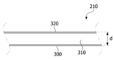
3 to 5, the
The
Here, the conductive fabric is a fabric composed of conductive fibers, and the conductive fibers may be a metal wire or a plain fiber coated with a metal film on the surface. The conductive fibers may be ordinary fibers in which metal particles are dispersed. When the conductive fiber is a metal wire, the diameter of the metal wire may be 10 탆 to 100 탆. If the diameter of the metal wire is less than 10 mu m, the strength of the metal wire may be too weak to process the fabric. If the diameter of the metal wire is more than 100 mu m, the rigidity of the metal wire may be high and the flexibility of the fabric may deteriorate. It can damage the equipment, and the user is likely to feel a sense of heterogeneity. At this time, the metal wire may be Cu, Ni, or a stainless steel alloy. The stainless alloy may be, for example, a martensitic stainless alloy, a ferritic stainless alloy, an austenitic stainless alloy, a two-phase stainless alloy, a precipitation hardening stainless alloy, or the like. When the metal wire is a stainless steel alloy, corrosion resistance of the
When the conductive fiber is a general fiber coated with a metal film on the surface, the metal film can be formed by a method in which the metal particles are coated on the surface of the ordinary fiber by a plating method or a vapor deposition method. At this time, the metal particles may be Cu, Ni, or a stainless alloy, and the thickness of the metal film may be 1 to 50 탆. If the thickness of the metal film is less than 1 탆, the conductivity may be low, which may cause a loss in signal transmission. If the thickness of the metal film exceeds 50 탆, the metal film may be easily separated from the surface of the fiber.
The
When the

Here, C is the capacitance and, A is an area that overlaps the
The
A plurality of second
The wires 324-11, 324-12, ..., 324-1n, 324-21, 324-22, ..., and 324-1m made of the conductive fabric are electrically connected to the respective second conductive regions 322- 322-1, 322-12, ..., 322-1n, 322-21, 322-22, ..., 322-1m, and connected to the copper wiring inserted in the
The
In a case where the
At this time, as shown in Figs. 6 to 7, each of the second conductive regions 322-11, 322-12, ..., 322-1n, 322-21, 322-22, ..., 322-1m The wires 324-11, 324-12, ..., 324-1n, 324-21, 324-22, ..., and 324-1m drawn out from the first
More specifically, the wirings 324-n drawn out from the respective second conductive regions 322-11, 322-12, ..., 322-1 n, 322-21, 322-22, The distance a between the edges of the first
Here, the wirings 324-11 and 324 (FIG. 32) drawn out from the respective second conductive regions 322-11, 322-12, ..., 322-1n, 322-21, 322-22, -12, ..., 324-1n, 324-21, 324-22, ..., 324-1m may be disposed between the two first
Here, the
Meanwhile, according to the embodiment of the present invention, the two first
At this time, at least three second conductive regions may be disposed on one first conductive region. When at least three second conductive regions are disposed on one first conductive region, at least three pairs of left and right capacitance variation amounts can be obtained, so that the resolution of pressure sensing can be increased.
According to one embodiment of the present invention, the
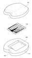
FIG. 8 is a sectional view of a seat plate incorporating a pressure sensing sensor according to an embodiment of the present invention, and FIG. 9 is an exploded view of a seat plate incorporating a pressure sensing sensor according to an embodiment of the present invention.
8 to 9, the
Thus, if the
At this time, the
9, a
Further, the bottom surface of the
Here, the
At this time, the thickness of the
That is, the thickness of the
In addition, the modulus of elasticity of the
8 to 9, the
The
It will be apparent to those skilled in the art that various modifications and variations can be made in the present invention without departing from the spirit or scope of the present invention as defined by the following claims It can be understood that
110:
112: first sheet layer
114: second sheet layer
210: Pressure sensor
Claims (8)
A pressure sensor disposed between the first sheet layer and the second sheet layer,
A signal processor connected to the pressure sensor for processing electrical signals generated by the pressure sensor,
A control unit for generating a control signal in accordance with a result processed by the signal processing unit,
Lt; / RTI >
The pressure sensor
A first electrode layer including a first conductive region made of a conductive fabric,
An elastic dielectric layer disposed on the first electrode layer,
A second electrode layer disposed on the elastic dielectric layer, the second electrode layer comprising a second conductive region comprising a conductive fabric, and
A flexible circuit board electrically connected to the first electrode layer and the second electrode layer,
The pressure sensing chair comprising:
Wherein the first sheet layer further comprises a groove for receiving the pressure sensing sensor,
Wherein the pressure sensing sensor is disposed within the groove.
Wherein the thickness of the second sheet layer is less than the thickness of the first sheet layer.
Wherein the thickness of the second sheet layer is 1 mm to 5 mm.
Wherein the modulus of elasticity of the second sheet layer is greater than the modulus of elasticity of the first sheet layer.
Wherein the density of the second sheet layer is greater than the density of the first sheet layer.
And a plurality of second conductive regions having a smaller area than the first conductive region are disposed on the first conductive region at a predetermined interval.
Wherein the first electrode layer comprises two first conducting regions connected to each other by a conductive fabric,
Wherein the second electrode layer comprises a plurality of second conductive regions disposed on one first conductive region and a plurality of second conductive regions disposed on another one of the first conductive regions.
Priority Applications (1)
| Application Number | Priority Date | Filing Date | Title |
|---|---|---|---|
| KR1020150187460A KR20170077514A (en) | 2015-12-28 | 2015-12-28 | Chair of sensing pressure |
Applications Claiming Priority (1)
| Application Number | Priority Date | Filing Date | Title |
|---|---|---|---|
| KR1020150187460A KR20170077514A (en) | 2015-12-28 | 2015-12-28 | Chair of sensing pressure |
Publications (1)
| Publication Number | Publication Date |
|---|---|
| KR20170077514A true KR20170077514A (en) | 2017-07-06 |
Family
ID=59354182
Family Applications (1)
| Application Number | Title | Priority Date | Filing Date |
|---|---|---|---|
| KR1020150187460A KR20170077514A (en) | 2015-12-28 | 2015-12-28 | Chair of sensing pressure |
Country Status (1)
| Country | Link |
|---|---|
| KR (1) | KR20170077514A (en) |
Cited By (1)
| Publication number | Priority date | Publication date | Assignee | Title |
|---|---|---|---|---|
| WO2019116919A1 (en) * | 2017-12-15 | 2019-06-20 | アルプスアルパイン株式会社 | Sensor device, production method therefor, and vehicle seat |
-
2015
- 2015-12-28 KR KR1020150187460A patent/KR20170077514A/en unknown
Cited By (4)
| Publication number | Priority date | Publication date | Assignee | Title |
|---|---|---|---|---|
| WO2019116919A1 (en) * | 2017-12-15 | 2019-06-20 | アルプスアルパイン株式会社 | Sensor device, production method therefor, and vehicle seat |
| CN111542264A (en) * | 2017-12-15 | 2020-08-14 | 阿尔卑斯阿尔派株式会社 | Sensor device, method for manufacturing the same, and vehicle seat |
| US20200298530A1 (en) * | 2017-12-15 | 2020-09-24 | Alps Alpine Co., Ltd. | Sensor device, method of manufacturing sensor device, and vehicle seat |
| US11794448B2 (en) | 2017-12-15 | 2023-10-24 | Alps Alpine Co., Ltd. | Sensor device, method of manufacturing sensor device, and vehicle seat |
Similar Documents
| Publication | Publication Date | Title |
|---|---|---|
| CN108135362B (en) | Pressure sensing chair | |
| US10876907B2 (en) | Pressure detection sensor having a plurality of dielectric layers and a plurality of electrode layers with conductive paths and wiring portions | |
| KR101753247B1 (en) | Pressure sensing sensor and pressure sensing apparatus comprising the same | |
| JP5995362B2 (en) | Distribution amount sensor and distribution amount measurement system | |
| KR20180117893A (en) | Pressure sensor | |
| US10955282B2 (en) | Pressure detecting sensor | |
| KR20180038757A (en) | Apparatus of sensing pressure | |
| KR20180117891A (en) | Pressure sensing sensor and pressure sensing apparatus comprising the same | |
| US11553753B2 (en) | Pressure sensing insole | |
| KR20180049677A (en) | Insol of sensing pressure | |
| KR101783413B1 (en) | Sensor for detecting pressure and insole of sensing pressure including the same | |
| CN115200753A (en) | Fabric pressure sensor array and pressure distribution mapping system | |
| KR102492375B1 (en) | Chair of sensing pressure | |
| KR20170074045A (en) | Chair of sensing pressure | |
| JP6829365B2 (en) | Pressure sensors, pressure sensor manufacturing methods, bed devices and automotive seats | |
| KR20170077514A (en) | Chair of sensing pressure | |
| KR20180117889A (en) | Pressure sensor | |
| KR20170081482A (en) | Chair of sensing pressure | |
| JP2646387B2 (en) | Distributed tactile sensor for curved surfaces | |
| KR102472286B1 (en) | Sensor for detecting pressrue | |
| KR102461696B1 (en) | Chair of sensing pressure | |
| KR20170131988A (en) | Sensor for detecting pressure and insol of sensing pressure including the same | |
| KR20180117895A (en) | Pressure sensing sensor and pressure sensing apparatus comprising the same | |
| KR102568540B1 (en) | Sensor for detecting pressrue | |
| KR102467998B1 (en) | Sensor for detecting pressrue |