EP3724927B1 - Abdeckplatte für funktionalisierte infrastruktur - Google Patents
Abdeckplatte für funktionalisierte infrastruktur Download PDFInfo
- Publication number
- EP3724927B1 EP3724927B1 EP18836835.1A EP18836835A EP3724927B1 EP 3724927 B1 EP3724927 B1 EP 3724927B1 EP 18836835 A EP18836835 A EP 18836835A EP 3724927 B1 EP3724927 B1 EP 3724927B1
- Authority
- EP
- European Patent Office
- Prior art keywords
- type
- infrastructure
- electrical energy
- cavity
- converter
- Prior art date
- Legal status (The legal status is an assumption and is not a legal conclusion. Google has not performed a legal analysis and makes no representation as to the accuracy of the status listed.)
- Active
Links
- 230000001939 inductive effect Effects 0.000 claims description 64
- 230000005540 biological transmission Effects 0.000 claims description 61
- 238000007306 functionalization reaction Methods 0.000 claims description 40
- 230000008878 coupling Effects 0.000 claims description 29
- 238000010168 coupling process Methods 0.000 claims description 29
- 238000005859 coupling reaction Methods 0.000 claims description 29
- 230000003068 static effect Effects 0.000 claims description 23
- 230000011664 signaling Effects 0.000 claims description 11
- 230000006698 induction Effects 0.000 claims description 10
- 230000002457 bidirectional effect Effects 0.000 claims description 7
- 238000004891 communication Methods 0.000 claims description 5
- 238000010438 heat treatment Methods 0.000 claims description 4
- 238000000034 method Methods 0.000 claims description 4
- 239000010410 layer Substances 0.000 description 40
- 239000011248 coating agent Substances 0.000 description 17
- 238000000576 coating method Methods 0.000 description 17
- UIAFKZKHHVMJGS-UHFFFAOYSA-N 2,4-dihydroxybenzoic acid Chemical compound OC(=O)C1=CC=C(O)C=C1O UIAFKZKHHVMJGS-UHFFFAOYSA-N 0.000 description 7
- 238000005253 cladding Methods 0.000 description 6
- 239000008393 encapsulating agent Substances 0.000 description 5
- 238000009434 installation Methods 0.000 description 5
- 230000008901 benefit Effects 0.000 description 4
- 238000004804 winding Methods 0.000 description 4
- 230000000712 assembly Effects 0.000 description 3
- 238000000429 assembly Methods 0.000 description 3
- 239000000463 material Substances 0.000 description 3
- 239000000203 mixture Substances 0.000 description 3
- 241001080024 Telles Species 0.000 description 2
- 238000004026 adhesive bonding Methods 0.000 description 2
- 238000004146 energy storage Methods 0.000 description 2
- 230000004907 flux Effects 0.000 description 2
- 239000002346 layers by function Substances 0.000 description 2
- 230000007257 malfunction Effects 0.000 description 2
- 229920003229 poly(methyl methacrylate) Polymers 0.000 description 2
- 239000004926 polymethyl methacrylate Substances 0.000 description 2
- 239000002356 single layer Substances 0.000 description 2
- 238000003860 storage Methods 0.000 description 2
- 230000035882 stress Effects 0.000 description 2
- 206010014405 Electrocution Diseases 0.000 description 1
- 239000012790 adhesive layer Substances 0.000 description 1
- 239000010426 asphalt Substances 0.000 description 1
- 238000012550 audit Methods 0.000 description 1
- 239000002131 composite material Substances 0.000 description 1
- 238000013016 damping Methods 0.000 description 1
- 230000002950 deficient Effects 0.000 description 1
- 230000006866 deterioration Effects 0.000 description 1
- 238000005538 encapsulation Methods 0.000 description 1
- -1 for example Substances 0.000 description 1
- 239000003365 glass fiber Substances 0.000 description 1
- 238000012423 maintenance Methods 0.000 description 1
- 238000007726 management method Methods 0.000 description 1
- 238000004519 manufacturing process Methods 0.000 description 1
- 230000003647 oxidation Effects 0.000 description 1
- 238000007254 oxidation reaction Methods 0.000 description 1
- 229920000642 polymer Polymers 0.000 description 1
- 239000002861 polymer material Substances 0.000 description 1
- 238000005096 rolling process Methods 0.000 description 1
- 238000007650 screen-printing Methods 0.000 description 1
- 230000035939 shock Effects 0.000 description 1
- 230000008646 thermal stress Effects 0.000 description 1
- 230000000007 visual effect Effects 0.000 description 1
Images


Classifications
-
- H—ELECTRICITY
- H02—GENERATION; CONVERSION OR DISTRIBUTION OF ELECTRIC POWER
- H02S—GENERATION OF ELECTRIC POWER BY CONVERSION OF INFRARED RADIATION, VISIBLE LIGHT OR ULTRAVIOLET LIGHT, e.g. USING PHOTOVOLTAIC [PV] MODULES
- H02S20/00—Supporting structures for PV modules
- H02S20/20—Supporting structures directly fixed to an immovable object
- H02S20/21—Supporting structures directly fixed to an immovable object specially adapted for motorways, e.g. integrated with sound barriers
-
- H—ELECTRICITY
- H01—ELECTRIC ELEMENTS
- H01L—SEMICONDUCTOR DEVICES NOT COVERED BY CLASS H10
- H01L31/00—Semiconductor devices sensitive to infrared radiation, light, electromagnetic radiation of shorter wavelength or corpuscular radiation and specially adapted either for the conversion of the energy of such radiation into electrical energy or for the control of electrical energy by such radiation; Processes or apparatus specially adapted for the manufacture or treatment thereof or of parts thereof; Details thereof
- H01L31/04—Semiconductor devices sensitive to infrared radiation, light, electromagnetic radiation of shorter wavelength or corpuscular radiation and specially adapted either for the conversion of the energy of such radiation into electrical energy or for the control of electrical energy by such radiation; Processes or apparatus specially adapted for the manufacture or treatment thereof or of parts thereof; Details thereof adapted as photovoltaic [PV] conversion devices
- H01L31/042—PV modules or arrays of single PV cells
- H01L31/048—Encapsulation of modules
-
- H—ELECTRICITY
- H02—GENERATION; CONVERSION OR DISTRIBUTION OF ELECTRIC POWER
- H02J—CIRCUIT ARRANGEMENTS OR SYSTEMS FOR SUPPLYING OR DISTRIBUTING ELECTRIC POWER; SYSTEMS FOR STORING ELECTRIC ENERGY
- H02J3/00—Circuit arrangements for ac mains or ac distribution networks
- H02J3/38—Arrangements for parallely feeding a single network by two or more generators, converters or transformers
- H02J3/381—Dispersed generators
-
- H—ELECTRICITY
- H02—GENERATION; CONVERSION OR DISTRIBUTION OF ELECTRIC POWER
- H02J—CIRCUIT ARRANGEMENTS OR SYSTEMS FOR SUPPLYING OR DISTRIBUTING ELECTRIC POWER; SYSTEMS FOR STORING ELECTRIC ENERGY
- H02J50/00—Circuit arrangements or systems for wireless supply or distribution of electric power
- H02J50/10—Circuit arrangements or systems for wireless supply or distribution of electric power using inductive coupling
-
- H—ELECTRICITY
- H02—GENERATION; CONVERSION OR DISTRIBUTION OF ELECTRIC POWER
- H02J—CIRCUIT ARRANGEMENTS OR SYSTEMS FOR SUPPLYING OR DISTRIBUTING ELECTRIC POWER; SYSTEMS FOR STORING ELECTRIC ENERGY
- H02J50/00—Circuit arrangements or systems for wireless supply or distribution of electric power
- H02J50/40—Circuit arrangements or systems for wireless supply or distribution of electric power using two or more transmitting or receiving devices
- H02J50/402—Circuit arrangements or systems for wireless supply or distribution of electric power using two or more transmitting or receiving devices the two or more transmitting or the two or more receiving devices being integrated in the same unit, e.g. power mats with several coils or antennas with several sub-antennas
-
- H—ELECTRICITY
- H02—GENERATION; CONVERSION OR DISTRIBUTION OF ELECTRIC POWER
- H02S—GENERATION OF ELECTRIC POWER BY CONVERSION OF INFRARED RADIATION, VISIBLE LIGHT OR ULTRAVIOLET LIGHT, e.g. USING PHOTOVOLTAIC [PV] MODULES
- H02S20/00—Supporting structures for PV modules
- H02S20/20—Supporting structures directly fixed to an immovable object
-
- H—ELECTRICITY
- H02—GENERATION; CONVERSION OR DISTRIBUTION OF ELECTRIC POWER
- H02S—GENERATION OF ELECTRIC POWER BY CONVERSION OF INFRARED RADIATION, VISIBLE LIGHT OR ULTRAVIOLET LIGHT, e.g. USING PHOTOVOLTAIC [PV] MODULES
- H02S40/00—Components or accessories in combination with PV modules, not provided for in groups H02S10/00 - H02S30/00
- H02S40/30—Electrical components
- H02S40/32—Electrical components comprising DC/AC inverter means associated with the PV module itself, e.g. AC modules
-
- H—ELECTRICITY
- H02—GENERATION; CONVERSION OR DISTRIBUTION OF ELECTRIC POWER
- H02S—GENERATION OF ELECTRIC POWER BY CONVERSION OF INFRARED RADIATION, VISIBLE LIGHT OR ULTRAVIOLET LIGHT, e.g. USING PHOTOVOLTAIC [PV] MODULES
- H02S40/00—Components or accessories in combination with PV modules, not provided for in groups H02S10/00 - H02S30/00
- H02S40/30—Electrical components
- H02S40/34—Electrical components comprising specially adapted electrical connection means to be structurally associated with the PV module, e.g. junction boxes
-
- H—ELECTRICITY
- H02—GENERATION; CONVERSION OR DISTRIBUTION OF ELECTRIC POWER
- H02S—GENERATION OF ELECTRIC POWER BY CONVERSION OF INFRARED RADIATION, VISIBLE LIGHT OR ULTRAVIOLET LIGHT, e.g. USING PHOTOVOLTAIC [PV] MODULES
- H02S40/00—Components or accessories in combination with PV modules, not provided for in groups H02S10/00 - H02S30/00
- H02S40/30—Electrical components
- H02S40/36—Electrical components characterised by special electrical interconnection means between two or more PV modules, e.g. electrical module-to-module connection
-
- H—ELECTRICITY
- H02—GENERATION; CONVERSION OR DISTRIBUTION OF ELECTRIC POWER
- H02J—CIRCUIT ARRANGEMENTS OR SYSTEMS FOR SUPPLYING OR DISTRIBUTING ELECTRIC POWER; SYSTEMS FOR STORING ELECTRIC ENERGY
- H02J2300/00—Systems for supplying or distributing electric power characterised by decentralized, dispersed, or local generation
- H02J2300/20—The dispersed energy generation being of renewable origin
- H02J2300/22—The renewable source being solar energy
- H02J2300/24—The renewable source being solar energy of photovoltaic origin
-
- Y—GENERAL TAGGING OF NEW TECHNOLOGICAL DEVELOPMENTS; GENERAL TAGGING OF CROSS-SECTIONAL TECHNOLOGIES SPANNING OVER SEVERAL SECTIONS OF THE IPC; TECHNICAL SUBJECTS COVERED BY FORMER USPC CROSS-REFERENCE ART COLLECTIONS [XRACs] AND DIGESTS
- Y02—TECHNOLOGIES OR APPLICATIONS FOR MITIGATION OR ADAPTATION AGAINST CLIMATE CHANGE
- Y02B—CLIMATE CHANGE MITIGATION TECHNOLOGIES RELATED TO BUILDINGS, e.g. HOUSING, HOUSE APPLIANCES OR RELATED END-USER APPLICATIONS
- Y02B10/00—Integration of renewable energy sources in buildings
- Y02B10/10—Photovoltaic [PV]
-
- Y—GENERAL TAGGING OF NEW TECHNOLOGICAL DEVELOPMENTS; GENERAL TAGGING OF CROSS-SECTIONAL TECHNOLOGIES SPANNING OVER SEVERAL SECTIONS OF THE IPC; TECHNICAL SUBJECTS COVERED BY FORMER USPC CROSS-REFERENCE ART COLLECTIONS [XRACs] AND DIGESTS
- Y02—TECHNOLOGIES OR APPLICATIONS FOR MITIGATION OR ADAPTATION AGAINST CLIMATE CHANGE
- Y02E—REDUCTION OF GREENHOUSE GAS [GHG] EMISSIONS, RELATED TO ENERGY GENERATION, TRANSMISSION OR DISTRIBUTION
- Y02E10/00—Energy generation through renewable energy sources
- Y02E10/50—Photovoltaic [PV] energy
- Y02E10/56—Power conversion systems, e.g. maximum power point trackers
Definitions
- the present invention relates to a coating slab for a functionalized infrastructure.
- the invention also relates to a contactless energy transmission system employing said coating slab as well as a functionalized infrastructure employing said system.
- infrastructure in a nonlimiting manner, is meant a roadway or highway type, but also a wall or a roof.
- Referenced documents FR3016257A1 and US8080901B2 describe such road solutions functionalized from photovoltaic cells or energy converters of the piezoelectric or thermoelectric type.
- the documents WO2016 / 16165A1 and WO2016 / 16170A1 describe for their part a multilayer structure of a photovoltaic module, which can be used to produce the wearing course of a functionalized pavement.
- This multilayer structure has in particular sufficient mechanical characteristics to absorb shocks and undergo the various mechanical stresses of a wearing course of a roadway.
- Each of the documents CN 107 142 815 A and US 2005/199282 A1 describes a cladding slab for a functionalized infrastructure formed of a one-piece assembly comprising an assembly for electrical functionalization of said slab comprising an outer layer, and an electronic block connected to said assembly for electrical functionalization and comprising at least one bidirectional static converter.
- SELV type voltage is meant a voltage less than 60V.
- the upper voltage (low voltage) should only be accessible from a greater depth.
- the aim of the invention is to provide a solution for producing a functionalized infrastructure in a simple, inexpensive manner, which is easy to install and maintain in the event of a malfunction and which makes it possible to take into account the constraints in terms of safety voltage mentioned. above.
- the electrical functionalization assembly comprises an electrical energy generator unit.
- the electrical energy generator unit may include photovoltaic cells intended to convert light energy into electrical energy.
- the electrical functionalization assembly comprises an electrical energy receiver unit.
- the electric energy receiver unit may include an electronic light and / or sound signaling circuit.
- the electrical energy receiver unit may include a device for recharging an electrical appliance by induction.
- the electric energy receiver unit may include a vehicle counting device.
- the electrical energy receiver unit may include one or more terminals for connection to one or more wireless communication networks.
- the electric energy receiver unit may include a heating structure.
- the first part comprises n static converter (s), each associated with an inductive coupler distinct from the first part.
- the n static converter (s) are of the AC / DC type and the system comprises a central converter of the DC / AC type and the n static converter (s) of the AC / DC type are connected. in parallel with said central converter.
- the system may include an electrical energy storage module connected in parallel with the n converter (s) connected to the central converter.
- the n static converter (s) are of the AC / AC type.
- the system comprises a central AC / AC converter and in that the n inductive coupler (s) of the first part are connected in parallel to said central AC / AC converter.
- the n static converter (s) are of the DC / AC type and the system comprises a central converter of the AC / AC type and the n static converter (s) of the DC / AC type are connected in parallel to said central converter.
- the n covering slabs are juxtaposed so as to present their external surface with their external layer situated in the same plane.
- infrastructure is understood to mean, for example, a traffic area.
- trafficable area is understood to mean, without limitation, any area provided for the movement of pedestrians and / or vehicles, such as, for example, a roadway or motorway type, a cycle path, a sidewalk or a parking lot.
- the infrastructure 1 to be functionalized comprises a lower layer 10, provided with a surface 100 to be covered with a functional layer which allows said infrastructure 1 to be functionalized.
- the invention aims in particular to produce said functional layer by using covering slabs positioned in a suitable manner, for example adjacent and contiguous, to at least partially cover the surface 100 of the lower layer 10 of said infrastructure 1.
- the slabs are for example all of an identical shape, for example rectangular or square.
- the lower layer will for example be composed of an asphalt mix.
- the lower layer does not form part of the invention, any other monolayer or multilayer structure can be envisaged.
- a covering slab 2 in accordance with the invention has the characteristics described below.
- the panel 2 of the invention is in the form of a one-piece element, that is to say forming only one piece. It advantageously has a first face, called the upper face F1, intended to form the external face of the infrastructure and a lower face F2 opposite and preferably parallel to the upper face. Between its two faces, the slab has several assemblies or functional blocks. These assemblies and functional blocks will preferably be housed in one or more hermetic boxes fixed together and having, if necessary, electrical connection means. Its upper face F1 is advantageously flat. This outer layer, defining the contour of the slab, may be of any possible shape.
- the covering slab 2 thus comprises an electrical functionalization assembly 20 which makes it possible to confer on the slab exclusively an electrical function of the type of electrical energy generator or an electrical function of the type of receiver of electrical energy (that is, say consumer).
- the infrastructure comprising several slabs of this type may for its part be equipped with one or more functions, depending on the type of slabs used.
- this electrical functionalization assembly 20 of the tile comprises a first layer 200 having an upper face, also called the external face, forming the upper face F1 of the tile 2 mentioned above, and intended to represent the surface of bearing of the traffic area.
- the coating slab 2 comprises an electronic block 21 connected to the electrical functionalization assembly 20 and which comprises at least one converter 210.
- the coating slab 2 also comprises a contactless energy transmission block 22 provided with at least one inductive coupler.
- This block will for example be fixed against the lower face F2 defined above, by any possible fixing means and electrically connected to the various circuits located above it.
- the electrical functionalization assembly 20 can take different configurations depending on the functionality of the generator or receiver type. add to the slab and to the infrastructure 1. It should be noted that the electronic unit 21 and the contactless energy transmission unit 22 of the slab which will be detailed below will preferably always be identical, whatever the configuration of the slab. the electrical functionalization assembly 20.
- the electrical functionalization assembly 20 is in the form of a photovoltaic module.
- it comprises the structure described in the two patent applications no. WO2016 / 16165A1 and WO2016 / 16170A1 and represented on the figure 2 .
- the first layer 200 described above is transparent over its entire thickness so as to allow a luminous flux to pass.
- transparent is meant that the material forming the first layer is at least partially transparent to visible light.
- the first layer 200 will for example be produced in the form of a single plate or of several juxtaposed plates. It will for example be made from a transparent polymer material, such as, for example, polymethyl methacrylate (PMMA).
- PMMA polymethyl methacrylate
- the photovoltaic module comprises a plurality of photovoltaic cells 201 connected together in series or in series / parallel. In known manner, these are intended to capture the light flux which passes through the first layer.
- the photovoltaic module comprises an encapsulating assembly in which the photovoltaic cells are encapsulated.
- This encapsulant assembly preferably consists of two layers 202a, 202b of encapsulating material, between which the photovoltaic cells are encapsulated.
- a rolling operation is carried out to melt the two layers 202a, 202b of encapsulation into a single layer in which the photovoltaic cells 201 are embedded.
- the manufacturing process is detailed in the two patent applications cited above, incorporated here by reference. As this does not form part of the invention, it is not described precisely in the present application.
- the photovoltaic cells 201 are housed in a volume, preferably hermetic, formed by the assembly of the two layers of the assembly.
- the photovoltaic module comprises a second layer 203, forming the rear face of the module.
- the encapsulant assembly is positioned between the first layer 200 and this second layer 203.
- This second layer 203 will for example be made of a material of the composite type, for example of the polymer / glass fiber type.
- the photovoltaic module advantageously comprises an intermediate layer 204 called "damping" located between the first layer 200 and the upper layer 202a of the encapsulating assembly (202a, 202b) and allowing the assembly, in particular by gluing, of the first layer 200 on the encapsulating assembly.
- the photovoltaic module advantageously comprises an adhesive layer (not shown) situated between the encapsulant assembly and the second layer 203. This layer will be used for the assembly, in particular by gluing, of the second layer 203 on the encapsulant assembly.
- the electrical functionalization assembly may exclusively comprise an electrical energy receiving circuit.
- the electrical functionalization assembly 20 may include an electronic light and / or sound signaling circuit.
- the electronic light signaling circuit comprises, for example, one or more light diodes making it possible to provide lighting.
- the structure of the electrical functionalization assembly 20 is similar to that of the first configuration of photovoltaic type. The differences lie in the fact that it uses a signaling unit including light diodes.
- the electrical functionalization assembly may include an induction electric vehicle recharging module. This solution makes it possible to recharge an electric vehicle when it is stationary on the road or in a parking space.
- the electrical functionalization assembly may include one or more electrical outlets so as to connect all types of electrical devices therein.
- the electrical functionalization assembly can include all types of sensors, for example of the temperature sensor type or of the vehicle counting type.
- the electrical functionalization assembly can include one or more terminals for connection to one or more wireless communication networks.
- This will for example be a terminal operating according to a known communication protocol such as WIFI, Bluetooth, 3G, 4G or other equivalent protocol. It will then be a question of proposing a panel equipped with one or more of these communication functions.
- the electrical functionalization assembly may comprise a heating structure comprising, for example, resistors or a mesh making it possible to heat the infrastructure, in particular to defrost it in winter.
- the coating slab 2 of the invention further comprises an electronic unit 21 which comprises at least one static voltage converter 210 which is bidirectional in current. Thanks to this converter, depending on its function, the panel 2 can act as a current generator or as a current receiver.
- the voltage converter will thus be of the DC / AC type to convert the direct current supplied by the photovoltaic cells into alternating current.
- the converter will be of a topology adapted to the type of receiver used.
- the voltage converter will be of the AC / DC type, the electronic signaling circuit being connected on the DC side.
- the converter will be of the AC / AC type.
- the voltage converter will be of the AC / AC type.
- the panel 2 finally comprises a contactless energy transmission block 22 which comprises an inductive coupler 220.
- this inductive coupler 220 comprises a winding of turns and is intended to be positioned opposite a second inductive coupler for carrying out a transfer of electrical energy without contact, that is to say wireless, by electromagnetic coupling.
- One of the two couplers thus forms the primary of a transformer and the other of the two couplers forms the secondary of the transformer.
- the transfer of energy between the two couplers will be carried out in one direction or the other.
- the electrical functionalization assembly includes a current generator (for example a photovoltaic module), the energy transfer will be carried out from the inductive coupler of the plate to the second coupler.
- the electrical functionalization assembly includes one or more receivers (for example light diodes), the energy transfer will be done in the other direction, that is to say from the second coupler to the power coupler. the slab.
- the arrangement of the inductive coupler 220 in the contactless energy transmission unit 22 defines a coupling surface SC2 located opposite the upper face F1 of the slab and advantageously parallel to the lower face F2 of the slab.
- the inductive coupler 220 has two terminals which are connected to the voltage converter 210 of the block 21 mentioned above.
- the contactless energy transmission unit 22 can be produced in the form of an independent element fixed to the panel 2 or be integrated into the electronic unit described above.
- the block 22 can in particular include an independent housing enclosing the inductive coupler 220 or be housed in the same housing with the electronic block 21.
- the winding forming the inductive coupler 220 may be produced in different configurations. This will for example be a planar type coil, the plane of which defined by the coil defines the coupling surface mentioned above.
- the winding of the planar coil is for example produced by screen printing on a printed circuit. One of the faces of the printed circuit then forms the coupling surface defined above.
- the invention also resides in the contactless (in other words wireless) energy transmission system in which is included one or more cladding tiles 2 of the type described above.
- This system thus consists of two parts, a first part 3 and a second part, between which the contactless energy transmission is operated.
- the second part of the system is formed by n cladding slabs 2 as described above, n being greater than or equal to 1.
- all the cladding slabs 2 used in this second part of the system could be of identical functions, then offering a single functionality to the system (for example only photovoltaic type slabs), or of different functions so as to offer several functionalities to the system (for example a mixture of slabs photovoltaic type with panels having a receiver type functionalization assembly (eg: light diodes).
- the first part 3 of the system comprises for its part n contactless energy transmission blocks 32, n being greater than or equal to 1.
- Each block 32 comprises an inductive coupler 320.
- Each inductive coupler 320 of this first part is intended for be associated with an inductive coupler 220 distinct from the second part.
- the inductive coupler 320 used in the first part will have a mechanical architecture identical to that of the inductive coupler of the plate with which it is associated. It thus has a coupling surface SC1 intended to be positioned in parallel with the coupling surface SC2 of the slab so as to ensure contactless energy transfer.
- the positioning characteristics between two windings are well known in the state of the art and are therefore not described in the present application.
- the positioning solution adopted will be optimal along the x axis and the y axis and possibly variable in the third dimension (according to the height defined by the z axis).
- the documents which relate in particular to induction charging solutions describe such characteristics.
- each contactless energy transmission block 32 has a structure in which the inductive coupler 320 is housed in a first housing 33 which comprises at least one wall defining an outer face, preferably flat, and an inner face opposite which the coupling surface SC1 of the inductive coupler 320 of the block is positioned.
- This first housing will advantageously be hermetic and particularly resistant to be used in an infrastructure such as one of those described above.
- the contactless energy transmission unit 32 may include a suitable static converter 310 comprising two connection terminals between which the inductive coupler 320 is connected.
- This static converter 310 will be of the AC / DC or AC / type. AC, the inductive coupler being connected on the AC side.
- the unit advantageously comprises a second housing 34, in which said static converter 310 is housed. This second housing is fixed to the first housing. The two boxes are for example fixed one on the other. The second housing extends below the first housing opposite the coupling surface. Electrical connection means are provided to ensure the electrical connection between the inductive coupler and the converter.
- any other arrangement of the inductive coupler and of the converter could be envisaged.
- the advantage of the implementation cited above is based on easier thermal management of the static converter in the mix, since it is further away from external thermal stresses.
- Each contactless energy transmission unit 32 of the first part 3 is electrically connected or included in an electrical architecture.
- This electrical architecture may differ, in particular depending on the functions of the slabs 2 used.
- This first architecture makes it possible in particular to work at a relatively high frequency (at least 100 kHz) at the level of the couplers, making it possible to guarantee the highest possible coupling efficiency, while maintaining a coupling architecture (formed by the two couplers facing each other). relatively compact. In fact, the higher the transmission frequency, the more compact the couplers used at iso-power, their volume being directly linked to their frequency of use.
- This second architecture of the system does not use converters in its first part but uses a central 4-2 converter of the AC / AC type to which the couplers of the first part are connected in parallel.
- This architecture presents the advantage of reducing the number of power converters used.
- the frequency on the AC bus will be a few kHz. It will be necessary to adopt a compromise between the various parameters which are the frequency on the AC bus, the efficiency of each inductive coupler of the first part and the line losses.
- This third architecture is freed from the central converter of previous architectures.
- This fourth architecture makes it possible to show what would be the structure of the system in a functionalized infrastructure equipped with panels with several distinct functions (photovoltaic, signaling, induction charging, etc.). It is in no way limiting in the number of functions available and in the functions offered.
- all of the converters are bidirectional in current in order in particular to allow the storage of energy in the storage module and the use of the energy stored in this module.
- the invention also consists in the arrangement of the system described above for its use in a functionalized infrastructure.
- an infrastructure such as a road comprises for example a lower layer 10 provided with a surface 100 to be covered.
- this surface 100 to be covered is intended to be covered, at least in part, by the coating tiles 2 of the invention.
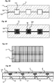
- the solution consists in making n cavities 101 or holes in the layer inferior 10 of the infrastructure, n being greater than or equal to 1 ( figure 4A ).
- Each cavity is intended to receive a contactless energy transmission block 32 from the first part of the system, each block 32 being positioned in the cavity so as to orient the coupling surface SC1 of its inductive coupler 320 upwards ( figure 4B ).
- each cavity 101 is always produced with standard dimensions, that is to say depth, section at the opening, shape of said section.
- the opening of the cavity 101 is then covered by a slab 2 ( figures 4C and 4D ).
- Mechanical positioning and centering means are preferably arranged to allow perfect positioning and centering of the panel 2 with respect to the cavity 101. This will for example be a matter of producing the housing of the panel which encloses the inductive coupler with dimensions adapted so that it cooperates, with minimal play, with the edge of the upper opening of the cavity.
- each cavity is adapted so that the coupling surface SC1 of the block 32 is located at a sufficient height to promote the transmission of energy between the two couplers 220, 320.
- each cavity 101 has for example a shape defining an upper part 101a of constant section, extended by a lower part 101b narrowed with respect to the upper part and also of constant section.
- the lower part of the cavity is intended to receive the second housing 34 of the contactless energy transmission unit and the upper part is intended to receive the first housing 33 of the contactless energy transmission unit.
- the infrastructure when the system comprises a first part with n energy transmission blocks and therefore n inductive couplers, with n greater than or equal to 2, the infrastructure is provided with n cavities of the type described above. so as to each accommodate a separate contactless energy transmission unit 32.
- the infrastructure comprises a trench 102 made in the lower layer 10 and connecting each cavity 101 to an adjacent cavity.
- each contactless energy transmission block 32 of the first part is thus connected to the adjacent block by at least one connecting cable 35, forming a form of bus according to one of the electrical architectures presented.
- each connecting cable 35 extends in a trench 102 connecting two cavities ( figure 5B ).
- the cable can take any suitable form and will be connected from one block to another. It could, for example, be a flexible sheet of wires.
- the figure 6A thus shows a surface entirely covered with tiles 2 according to the invention.
- the figure 6B shows for its part the slabs positioned adjacent to the surface 100 of the lower layer 10.
- the external surfaces of the n slabs positioned juxtaposed are arranged in the same plane, forming the plane of the roadway.
- the n slabs laid on the lower layer are therefore adjusted with respect to each other, in particular in terms of dimensions, to be perfectly contiguous and thus to pave the surface to be covered with the lower layer as much as possible.
Landscapes
- Engineering & Computer Science (AREA)
- Power Engineering (AREA)
- Computer Networks & Wireless Communication (AREA)
- Physics & Mathematics (AREA)
- Condensed Matter Physics & Semiconductors (AREA)
- Electromagnetism (AREA)
- General Physics & Mathematics (AREA)
- Computer Hardware Design (AREA)
- Microelectronics & Electronic Packaging (AREA)
- Charge And Discharge Circuits For Batteries Or The Like (AREA)
- Prevention Of Electric Corrosion (AREA)
Claims (21)
- Abdeckplatte (2) für eine Infrastruktur wie etwa eine Chaussee vom Typ einer Straße oder einer Autobahn, eine Mauer oder ein Dach, wobei die Infrastruktur durch das Hinzufügen einer Funktion vom Typ eines Generators elektrischer Energie und/oder vom Typ eines Empfängers elektrischer Energie funktionalisiert ist, wobei die Abdeckplatte aus einer einstückigen Vorrichtung gebildet ist, die- eine Vorrichtung (20) zum elektrischen Funktionalisieren der Abdeckplatte, die eine erste Schicht, die sogenannte äußere Schicht, aufweist,- einen elektronischen Block (21), der mit der Vorrichtung zum elektrischen Funktionalisieren verbunden ist und wenigstens einen statischen bidirektionalen Wandler (210) aufweist,
aufweist,
dadurch gekennzeichnet, daß die einstückige Vorrichtung außerdem- einen Block (22) zum kontaktlosen Übertragen von Energie aufweist, der einen mit zwei mit dem statischen bidirektionalen Wandler des elektronischen Blocks (21) verbundenen Anschlüssen versehenen induktiven Koppler (220) aufweist und eine von der äußeren Schicht abgewandte Kopplungsoberfläche aufweist. - Abdeckplatte gemäß Anspruch 1, dadurch gekennzeichnet, daß die Vorrichtung zum elektrischen Funktionalisieren einen Block zum Erzeugen elektrischer Energie aufweist.
- Abdeckplatte gemäß Anspruch 2, dadurch gekennzeichnet, daß der Block zum Erzeugen elektrischer Energie- Solarzellen (201) aufweist, die dazu bestimmt sind, eine Lichtenergie in eine elektrische Energie umzuwandeln.
- Abdeckplatte gemäß Anspruch 1, dadurch gekennzeichnet, daß die Vorrichtung zum elektrischen Funktionalisieren einen Block zum Empfangen elektrischer Energie aufweist.
- Abdeckplatte gemäß Anspruch 4, dadurch gekennzeichnet, daß der Block zum Empfangen elektrischer Energie eine elektronische Signalisierungsschaltung mit Licht und/oder Ton aufweist.
- Abdeckplatte gemäß Anspruch 4, dadurch gekennzeichnet, daß der Block zum Empfangen elektrischer Energie eine Vorrichtung zum Aufladen eines elektrischen Geräts durch Induktion aufweist.
- Abdeckplatte gemäß Anspruch 4, dadurch gekennzeichnet, daß der Block zum Empfangen elektrischer Energie eine Vorrichtung zum Zählen von Fahrzeugen aufweist.
- Abdeckplatte gemäß Anspruch 4, dadurch gekennzeichnet, daß der Block zum Empfangen elektrischer Energie einen oder mehrere Anschlüsse zum Verbinden mit einem oder mehreren Netzen für drahtlose Kommunikation aufweist.
- Abdeckplatte gemäß Anspruch 4, dadurch gekennzeichnet, daß der Block zum Empfangen elektrischer Energie eine Heizstruktur aufweist.
- System zur kontaktlosen Übertragung elektrischer Energie für eine Infrastruktur wie etwa eine Chaussee vom Typ einer Straße oder einer Autobahn, eine Wand oder ein Dach, wobei die Infrastruktur durch das Hinzufügen einer Funktion vom Typ eines Generators elektrischer Energie und/oder vom Typ eines Empfängers elektrischer Energie funktionalisiert ist,
dadurch gekennzeichnet, daß es- einen ersten Teil (3), der n Blöcke (32) zum kontaktlosen Übertragen von Energie aufweist, von denen jeder einen induktiven Koppler aufweist, wobei n größer als oder gleich 1 ist, wobei jeder induktive Koppler (320) eine Kopplungsoberfläche (SC1) aufweist,- einen zweiten Teil, der n Abdeckplatten (2) aufweist, wobei jede Abdeckplatte so wie in einem der Ansprüche 1 bis 9 definiert ist,
aufweist. - System gemäß Anspruch 10, dadurch gekennzeichnet, daß- der erste Teil (3) n Blöcke zum kontaktlosen Übertragen elektrischer Energie aufweist, wobei n größer als oder gleich 2 ist,- jeder induktive Koppler (320) des ersten Teils durch ein Verbindungskabel (35) elektrisch mit einem angrenzenden induktiven Koppler verbunden ist.
- System gemäß Anspruch 10 oder 11, dadurch gekennzeichnet, daß der erste Teil n statische Wandler (310) aufweist, die jeweils einem separaten induktiven Koppler (320) des ersten Teils zugeordnet sind.
- System gemäß Anspruch 12, dadurch gekennzeichnet, daß die n statischen Wandler im ersten Teil vom Typ AC/DC sind und daß das System einen zentralen Wandler (4) vom Typ DC/AC aufweist und daß die n statischen Wandler vom Typ AC/DC mit dem zentralen Wandler parallel verbunden sind.
- System gemäß Anspruch 13, dadurch gekennzeichnet, daß es ein zu den mit dem zentralen Wandler (4) verbundenen n Wandlern parallel verbundenes Modul (5) zum Speichern elektrischer Energie aufweist.
- System gemäß Anspruch 12, dadurch gekennzeichnet, daß die n statischen Wandler (310) im ersten Teil vom Typ AC/AC sind.
- System gemäß Anspruch 12, dadurch gekennzeichnet, daß es einen zentralen Wandler (4) vom Typ AC/AC aufweist und daß die n induktiven Koppler des ersten Teils mit dem zentralen Wandler AC/AC parallel verbunden sind.
- System gemäß Anspruch 12, dadurch gekennzeichnet, daß die n statischen Wandler im ersten Teil vom Typ DC/AC sind und daß das System einen zentralen Wandler (4) vom Typ AC/AC aufweist und daß die n statischen Wandler vom Typ DC/AC mit dem zentralen Wandler parallel verbunden sind.
- Infrastruktur wie etwa eine Chaussee vom Typ einer Straße oder einer Autobahn, eine Mauer oder ein Dach, wobei die Infrastruktur durch das Hinzufügen einer Funktion vom Typ eines Generators elektrischer Energie und/oder vom Typ eines Empfängers elektrischer Energie funktionalisiert ist und ein System zum kontaktlosen Übertragen elektrischer Energie aufweist, wobei die Infrastruktur eine untere Schicht (10) aufweist, die eine abzudeckende Oberfläche (100) aufweist und in der n Hohlräume (101) ausgeführt sind, wobei n größer als oder gleich 1 ist, wobei die Infrastruktur dadurch gekennzeichnet ist, daß sie- einen ersten Teil (3), der einen in jedem Hohlraum (101) untergebrachten induktiven Koppler (320) aufweist, um eine erste Kopplungsoberfläche (SC1) zu bilden,- einen zweiten Teil, der n wie in einem der Ansprüche 1 bis 9 definierte Abdeckplatten (2) aufweist, wobei jede Abdeckplatte (2) auf der abzudeckenden Oberfläche (100) so angeordnet ist, daß ein separater Hohlraum (101) abgedeckt wird und daß deren Außenseite nach außerhalb des Hohlraums und deren Kopplungsoberfläche (SC2) zum Inneren des Hohlraums hin, der Kopplungsoberfläche (SC1) des in dem Hohlraum untergebrachten induktiven Kopplers gegenüberliegend, gerichtet ist,aufweist.
- Funktionalisierte Infrastruktur gemäß Anspruch 18, dadurch gekennzeichnet, daß- die abzudeckende Oberfläche (100) der unteren Schicht (10) n Hohlräume aufweist, wobei n größer als oder gleich 2 ist,- die Infrastruktur eine Rinne (102) aufweist, die jeden Hohlraum (101) mit einem angrenzenden Hohlraum verbindet,- der erste Teil des Systems mehrere jeweils in einem separaten Hohlraum (101) untergebrachte induktive Koppler (320) aufweist,- die induktiven Koppler (320) von einem Hohlraum zu einem angrenzenden Hohlraum untereinander durch ein sich in der Rinne (102) erstreckendes Verbindungskabel (35) miteinander verbunden sind.
- Funktionalisierte Infrastruktur gemäß Anspruch 18 oder 19, dadurch gekennzeichnet, daß die n Abdeckplatten so nebeneinander angeordnet sind, daß die äußere Oberfläche von deren äußerer Schicht in einer selben Ebene liegt.
- Verfahren zum Installieren einer funktionalisierten Infrastruktur, wie sie in einem der Ansprüche 18 bis 20 definiert ist, wobei das Verfahren die folgenden Schritte aufweist:- Herstellen von n Hohlräumen (101) in der unteren Schicht, wobei n größer als oder gleich 2 ist,- Positionieren des ersten Teils derart, daß jeder Hohlraum mit einem separaten induktiven Koppler besetzt ist,- Positionieren einer separaten Abdeckplatte (2) über einem separaten Hohlraum (101) derart, daß deren Außenseite nach außerhalb des Hohlraums und deren Kopplungsoberfläche (SC2) zum Inneren des Hohlraums hin, der Kopplungsoberfläche (SC1) des in dem Hohlraum untergebrachten induktiven Kopplers gegenüberliegend, gerichtet ist.
Applications Claiming Priority (2)
| Application Number | Priority Date | Filing Date | Title |
|---|---|---|---|
| FR1762046A FR3074823B1 (fr) | 2017-12-13 | 2017-12-13 | Dalle de revetement pour infrastructure fonctionnalisee |
| PCT/FR2018/053099 WO2019115910A1 (fr) | 2017-12-13 | 2018-12-04 | Dalle de revêtement pour infrastructure fonctionnalisée |
Publications (2)
| Publication Number | Publication Date |
|---|---|
| EP3724927A1 EP3724927A1 (de) | 2020-10-21 |
| EP3724927B1 true EP3724927B1 (de) | 2021-09-15 |
Family
ID=61258421
Family Applications (1)
| Application Number | Title | Priority Date | Filing Date |
|---|---|---|---|
| EP18836835.1A Active EP3724927B1 (de) | 2017-12-13 | 2018-12-04 | Abdeckplatte für funktionalisierte infrastruktur |
Country Status (6)
| Country | Link |
|---|---|
| US (1) | US20210075362A1 (de) |
| EP (1) | EP3724927B1 (de) |
| CA (1) | CA3084843A1 (de) |
| ES (1) | ES2897558T3 (de) |
| FR (1) | FR3074823B1 (de) |
| WO (1) | WO2019115910A1 (de) |
Families Citing this family (3)
| Publication number | Priority date | Publication date | Assignee | Title |
|---|---|---|---|---|
| DE102015223615A1 (de) * | 2015-11-30 | 2017-06-01 | Bayerische Motoren Werke Aktiengesellschaft | Sekundärspuleneinheit mit einer Service-Öffnung |
| FR3115415B1 (fr) | 2020-10-19 | 2022-11-04 | Commissariat Energie Atomique | Equipement fonctionnalisé doté d'un ou plusieurs éléments de couverture fonctionnalisés |
| FR3116163A1 (fr) | 2020-11-09 | 2022-05-13 | Commissariat à l'Energie Atomique et aux Energies Alternatives | Elément de couverture fonctionnalisé et infrastructure comportant plusieurs éléments de couverture fonctionnalisés |
Family Cites Families (6)
| Publication number | Priority date | Publication date | Assignee | Title |
|---|---|---|---|---|
| WO2005086979A2 (en) * | 2004-03-11 | 2005-09-22 | Oleinick Energy, Llc | Photovoltaic-embedded surface |
| US8080901B2 (en) | 2009-03-16 | 2011-12-20 | Doraisamy Loganathan | Multi-source integrated electricity generation from novel smart roads and pavements |
| FR3016257A1 (fr) | 2014-01-09 | 2015-07-10 | Alex Hr Roustaei | Conversion, production, stockage, transport et distribution d'energie solaire pour route muni de gestion intelligente avec signalisation leds et systeme de recharge sans fil pour vehicules electrique |
| FR3024281B1 (fr) | 2014-07-28 | 2016-08-26 | Commissariat Energie Atomique | Module photovoltaique pour support rigide |
| FR3024285B1 (fr) | 2014-07-28 | 2016-09-02 | Commissariat Energie Atomique | Ensemble comportant un module photovoltaique applique sur une zone circulable |
| CN107142815A (zh) * | 2017-07-06 | 2017-09-08 | 长沙理工大学 | 一种基于太阳能发电路面的智能交通监控系统 |
-
2017
- 2017-12-13 FR FR1762046A patent/FR3074823B1/fr active Active
-
2018
- 2018-12-04 WO PCT/FR2018/053099 patent/WO2019115910A1/fr unknown
- 2018-12-04 US US16/772,211 patent/US20210075362A1/en not_active Abandoned
- 2018-12-04 EP EP18836835.1A patent/EP3724927B1/de active Active
- 2018-12-04 CA CA3084843A patent/CA3084843A1/fr not_active Abandoned
- 2018-12-04 ES ES18836835T patent/ES2897558T3/es active Active
Also Published As
| Publication number | Publication date |
|---|---|
| US20210075362A1 (en) | 2021-03-11 |
| FR3074823B1 (fr) | 2019-12-20 |
| EP3724927A1 (de) | 2020-10-21 |
| FR3074823A1 (fr) | 2019-06-14 |
| WO2019115910A1 (fr) | 2019-06-20 |
| CA3084843A1 (fr) | 2019-06-20 |
| ES2897558T3 (es) | 2022-03-01 |
Similar Documents
| Publication | Publication Date | Title |
|---|---|---|
| EP3724927B1 (de) | Abdeckplatte für funktionalisierte infrastruktur | |
| US8080901B2 (en) | Multi-source integrated electricity generation from novel smart roads and pavements | |
| FR3000543A1 (fr) | Systeme de capteur comportant un dispositif de couverture | |
| EP3583267B1 (de) | Lichtsignalisierungssplatte und zur verwendung solch einer platte fähiges system | |
| CN104813484A (zh) | 具有高转换效率的光伏组件 | |
| FR2925225A1 (fr) | Dispositif generateur d'energie comprenant un convertisseur photovoltaique et un convertisseur thermoelectrique, ce dernier etant inclus au sein du substrat support du convertisseur photovoltaique | |
| CA3130165A1 (fr) | Dispositif fonctionnel integrable dans une chaussee circulable et procede de fabrication d'une chaussee circulable avec un tel dispositif fonctionnel | |
| EP3175488B1 (de) | Fotovoltaikmodul für einen starren träger | |
| EP3499584B1 (de) | Funktionalisierte infrastruktur und verfahren zum aufbau einer solchen funktionalisierten infrastruktur | |
| FR3016257A1 (fr) | Conversion, production, stockage, transport et distribution d'energie solaire pour route muni de gestion intelligente avec signalisation leds et systeme de recharge sans fil pour vehicules electrique | |
| EP3590164A1 (de) | System zur verteilung von elektrischer energie, insbesondere von grüner energie | |
| WO2017114875A1 (fr) | Dispositif photovoltaïque avec boitier de jonction electrique, procede de fabrication et utilisation dudit dispositif | |
| EP3609050A1 (de) | Kontaktloses elektrisches verbindungssystem | |
| GB2451108A (en) | Photovoltaic Device | |
| EP3996244B1 (de) | Funktionalisiertes abdeckelement und infrastruktur mit mehreren solchen funktionalisierten abdeckelementen | |
| EP3667688B1 (de) | Elektrische einheit, die ein kapazitives element umfasst | |
| US10530018B2 (en) | Panel, a method for fabricating a panel and a method | |
| JP2019534398A (ja) | 多機能太陽電池パネル | |
| FR2940523A1 (fr) | Tuile photovoltaique. | |
| EP3985865A1 (de) | Funktionalisierte ausrüstung mit einem oder mehreren funktionalisierten abdeckelementen | |
| WO2018134507A1 (fr) | Panneau de charge sans fil, unité de stockage d'énergie équipée dudit panneau et système d'alimentation électrique chargeable | |
| WO2023145579A1 (ja) | 舗装構造物 | |
| WO2023118124A1 (fr) | Dispositif fonctionnel en structure multicouche dont l'une des couches comprend un materiau composite comportant une resine en polyurethane thermodurcissable et des fibres de verre et procede de fabrication d'un tel dispositif fonctionnel | |
| FR3129412A1 (fr) | Dispositif fonctionnel à sorties électriques directes et procédé de fabrication d’un tel dispositif fonctionnel | |
| FR3021476A1 (fr) | Infrastructure d'un reseau de telecommunication et dispositif d'interface d'une telle infrastructure |
Legal Events
| Date | Code | Title | Description |
|---|---|---|---|
| STAA | Information on the status of an ep patent application or granted ep patent |
Free format text: STATUS: UNKNOWN |
|
| STAA | Information on the status of an ep patent application or granted ep patent |
Free format text: STATUS: THE INTERNATIONAL PUBLICATION HAS BEEN MADE |
|
| PUAI | Public reference made under article 153(3) epc to a published international application that has entered the european phase |
Free format text: ORIGINAL CODE: 0009012 |
|
| STAA | Information on the status of an ep patent application or granted ep patent |
Free format text: STATUS: REQUEST FOR EXAMINATION WAS MADE |
|
| 17P | Request for examination filed |
Effective date: 20200612 |
|
| AK | Designated contracting states |
Kind code of ref document: A1 Designated state(s): AL AT BE BG CH CY CZ DE DK EE ES FI FR GB GR HR HU IE IS IT LI LT LU LV MC MK MT NL NO PL PT RO RS SE SI SK SM TR |
|
| AX | Request for extension of the european patent |
Extension state: BA ME |
|
| DAV | Request for validation of the european patent (deleted) | ||
| DAX | Request for extension of the european patent (deleted) | ||
| RIC1 | Information provided on ipc code assigned before grant |
Ipc: H02S 20/21 20140101ALI20210322BHEP Ipc: H02S 20/20 20140101ALI20210322BHEP Ipc: H02J 50/10 20160101ALI20210322BHEP Ipc: H01L 31/048 20140101ALI20210322BHEP Ipc: H02S 40/36 20140101ALI20210322BHEP Ipc: H02S 40/34 20140101ALI20210322BHEP Ipc: H02S 40/32 20140101ALI20210322BHEP Ipc: H01L 33/00 20100101ALI20210322BHEP Ipc: H01L 31/042 20140101AFI20210322BHEP |
|
| GRAP | Despatch of communication of intention to grant a patent |
Free format text: ORIGINAL CODE: EPIDOSNIGR1 |
|
| STAA | Information on the status of an ep patent application or granted ep patent |
Free format text: STATUS: GRANT OF PATENT IS INTENDED |
|
| INTG | Intention to grant announced |
Effective date: 20210503 |
|
| GRAS | Grant fee paid |
Free format text: ORIGINAL CODE: EPIDOSNIGR3 |
|
| GRAA | (expected) grant |
Free format text: ORIGINAL CODE: 0009210 |
|
| STAA | Information on the status of an ep patent application or granted ep patent |
Free format text: STATUS: THE PATENT HAS BEEN GRANTED |
|
| AK | Designated contracting states |
Kind code of ref document: B1 Designated state(s): AL AT BE BG CH CY CZ DE DK EE ES FI FR GB GR HR HU IE IS IT LI LT LU LV MC MK MT NL NO PL PT RO RS SE SI SK SM TR |
|
| REG | Reference to a national code |
Ref country code: CH Ref legal event code: EP |
|
| REG | Reference to a national code |
Ref country code: DE Ref legal event code: R096 Ref document number: 602018023754 Country of ref document: DE |
|
| REG | Reference to a national code |
Ref country code: IE Ref legal event code: FG4D Free format text: LANGUAGE OF EP DOCUMENT: FRENCH |
|
| REG | Reference to a national code |
Ref country code: AT Ref legal event code: REF Ref document number: 1431203 Country of ref document: AT Kind code of ref document: T Effective date: 20211015 |
|
| REG | Reference to a national code |
Ref country code: NL Ref legal event code: FP |
|
| REG | Reference to a national code |
Ref country code: LT Ref legal event code: MG9D |
|
| PG25 | Lapsed in a contracting state [announced via postgrant information from national office to epo] |
Ref country code: FI Free format text: LAPSE BECAUSE OF FAILURE TO SUBMIT A TRANSLATION OF THE DESCRIPTION OR TO PAY THE FEE WITHIN THE PRESCRIBED TIME-LIMIT Effective date: 20210915 Ref country code: RS Free format text: LAPSE BECAUSE OF FAILURE TO SUBMIT A TRANSLATION OF THE DESCRIPTION OR TO PAY THE FEE WITHIN THE PRESCRIBED TIME-LIMIT Effective date: 20210915 Ref country code: SE Free format text: LAPSE BECAUSE OF FAILURE TO SUBMIT A TRANSLATION OF THE DESCRIPTION OR TO PAY THE FEE WITHIN THE PRESCRIBED TIME-LIMIT Effective date: 20210915 Ref country code: BG Free format text: LAPSE BECAUSE OF FAILURE TO SUBMIT A TRANSLATION OF THE DESCRIPTION OR TO PAY THE FEE WITHIN THE PRESCRIBED TIME-LIMIT Effective date: 20211215 Ref country code: LT Free format text: LAPSE BECAUSE OF FAILURE TO SUBMIT A TRANSLATION OF THE DESCRIPTION OR TO PAY THE FEE WITHIN THE PRESCRIBED TIME-LIMIT Effective date: 20210915 Ref country code: HR Free format text: LAPSE BECAUSE OF FAILURE TO SUBMIT A TRANSLATION OF THE DESCRIPTION OR TO PAY THE FEE WITHIN THE PRESCRIBED TIME-LIMIT Effective date: 20210915 Ref country code: NO Free format text: LAPSE BECAUSE OF FAILURE TO SUBMIT A TRANSLATION OF THE DESCRIPTION OR TO PAY THE FEE WITHIN THE PRESCRIBED TIME-LIMIT Effective date: 20211215 |
|
| REG | Reference to a national code |
Ref country code: AT Ref legal event code: MK05 Ref document number: 1431203 Country of ref document: AT Kind code of ref document: T Effective date: 20210915 |
|
| PG25 | Lapsed in a contracting state [announced via postgrant information from national office to epo] |
Ref country code: LV Free format text: LAPSE BECAUSE OF FAILURE TO SUBMIT A TRANSLATION OF THE DESCRIPTION OR TO PAY THE FEE WITHIN THE PRESCRIBED TIME-LIMIT Effective date: 20210915 Ref country code: GR Free format text: LAPSE BECAUSE OF FAILURE TO SUBMIT A TRANSLATION OF THE DESCRIPTION OR TO PAY THE FEE WITHIN THE PRESCRIBED TIME-LIMIT Effective date: 20211216 |
|
| REG | Reference to a national code |
Ref country code: ES Ref legal event code: FG2A Ref document number: 2897558 Country of ref document: ES Kind code of ref document: T3 Effective date: 20220301 |
|
| PG25 | Lapsed in a contracting state [announced via postgrant information from national office to epo] |
Ref country code: AT Free format text: LAPSE BECAUSE OF FAILURE TO SUBMIT A TRANSLATION OF THE DESCRIPTION OR TO PAY THE FEE WITHIN THE PRESCRIBED TIME-LIMIT Effective date: 20210915 |
|
| PG25 | Lapsed in a contracting state [announced via postgrant information from national office to epo] |
Ref country code: IS Free format text: LAPSE BECAUSE OF FAILURE TO SUBMIT A TRANSLATION OF THE DESCRIPTION OR TO PAY THE FEE WITHIN THE PRESCRIBED TIME-LIMIT Effective date: 20220115 Ref country code: SM Free format text: LAPSE BECAUSE OF FAILURE TO SUBMIT A TRANSLATION OF THE DESCRIPTION OR TO PAY THE FEE WITHIN THE PRESCRIBED TIME-LIMIT Effective date: 20210915 Ref country code: SK Free format text: LAPSE BECAUSE OF FAILURE TO SUBMIT A TRANSLATION OF THE DESCRIPTION OR TO PAY THE FEE WITHIN THE PRESCRIBED TIME-LIMIT Effective date: 20210915 Ref country code: RO Free format text: LAPSE BECAUSE OF FAILURE TO SUBMIT A TRANSLATION OF THE DESCRIPTION OR TO PAY THE FEE WITHIN THE PRESCRIBED TIME-LIMIT Effective date: 20210915 Ref country code: PT Free format text: LAPSE BECAUSE OF FAILURE TO SUBMIT A TRANSLATION OF THE DESCRIPTION OR TO PAY THE FEE WITHIN THE PRESCRIBED TIME-LIMIT Effective date: 20220117 Ref country code: PL Free format text: LAPSE BECAUSE OF FAILURE TO SUBMIT A TRANSLATION OF THE DESCRIPTION OR TO PAY THE FEE WITHIN THE PRESCRIBED TIME-LIMIT Effective date: 20210915 Ref country code: EE Free format text: LAPSE BECAUSE OF FAILURE TO SUBMIT A TRANSLATION OF THE DESCRIPTION OR TO PAY THE FEE WITHIN THE PRESCRIBED TIME-LIMIT Effective date: 20210915 Ref country code: CZ Free format text: LAPSE BECAUSE OF FAILURE TO SUBMIT A TRANSLATION OF THE DESCRIPTION OR TO PAY THE FEE WITHIN THE PRESCRIBED TIME-LIMIT Effective date: 20210915 Ref country code: AL Free format text: LAPSE BECAUSE OF FAILURE TO SUBMIT A TRANSLATION OF THE DESCRIPTION OR TO PAY THE FEE WITHIN THE PRESCRIBED TIME-LIMIT Effective date: 20210915 |
|
| REG | Reference to a national code |
Ref country code: DE Ref legal event code: R097 Ref document number: 602018023754 Country of ref document: DE |
|
| PLBE | No opposition filed within time limit |
Free format text: ORIGINAL CODE: 0009261 |
|
| STAA | Information on the status of an ep patent application or granted ep patent |
Free format text: STATUS: NO OPPOSITION FILED WITHIN TIME LIMIT |
|
| PG25 | Lapsed in a contracting state [announced via postgrant information from national office to epo] |
Ref country code: MC Free format text: LAPSE BECAUSE OF FAILURE TO SUBMIT A TRANSLATION OF THE DESCRIPTION OR TO PAY THE FEE WITHIN THE PRESCRIBED TIME-LIMIT Effective date: 20210915 Ref country code: DK Free format text: LAPSE BECAUSE OF FAILURE TO SUBMIT A TRANSLATION OF THE DESCRIPTION OR TO PAY THE FEE WITHIN THE PRESCRIBED TIME-LIMIT Effective date: 20210915 |
|
| REG | Reference to a national code |
Ref country code: CH Ref legal event code: PL |
|
| 26N | No opposition filed |
Effective date: 20220616 |
|
| PG25 | Lapsed in a contracting state [announced via postgrant information from national office to epo] |
Ref country code: SI Free format text: LAPSE BECAUSE OF FAILURE TO SUBMIT A TRANSLATION OF THE DESCRIPTION OR TO PAY THE FEE WITHIN THE PRESCRIBED TIME-LIMIT Effective date: 20210915 |
|
| REG | Reference to a national code |
Ref country code: BE Ref legal event code: MM Effective date: 20211231 |
|
| PG25 | Lapsed in a contracting state [announced via postgrant information from national office to epo] |
Ref country code: LU Free format text: LAPSE BECAUSE OF NON-PAYMENT OF DUE FEES Effective date: 20211204 Ref country code: IE Free format text: LAPSE BECAUSE OF NON-PAYMENT OF DUE FEES Effective date: 20211204 |
|
| PG25 | Lapsed in a contracting state [announced via postgrant information from national office to epo] |
Ref country code: BE Free format text: LAPSE BECAUSE OF NON-PAYMENT OF DUE FEES Effective date: 20211231 |
|
| PG25 | Lapsed in a contracting state [announced via postgrant information from national office to epo] |
Ref country code: LI Free format text: LAPSE BECAUSE OF NON-PAYMENT OF DUE FEES Effective date: 20211231 Ref country code: CH Free format text: LAPSE BECAUSE OF NON-PAYMENT OF DUE FEES Effective date: 20211231 |
|
| P01 | Opt-out of the competence of the unified patent court (upc) registered |
Effective date: 20230524 |
|
| PG25 | Lapsed in a contracting state [announced via postgrant information from national office to epo] |
Ref country code: CY Free format text: LAPSE BECAUSE OF FAILURE TO SUBMIT A TRANSLATION OF THE DESCRIPTION OR TO PAY THE FEE WITHIN THE PRESCRIBED TIME-LIMIT Effective date: 20210915 |
|
| PG25 | Lapsed in a contracting state [announced via postgrant information from national office to epo] |
Ref country code: HU Free format text: LAPSE BECAUSE OF FAILURE TO SUBMIT A TRANSLATION OF THE DESCRIPTION OR TO PAY THE FEE WITHIN THE PRESCRIBED TIME-LIMIT; INVALID AB INITIO Effective date: 20181204 |
|
| PGFP | Annual fee paid to national office [announced via postgrant information from national office to epo] |
Ref country code: FR Payment date: 20230926 Year of fee payment: 6 |
|
| PGFP | Annual fee paid to national office [announced via postgrant information from national office to epo] |
Ref country code: GB Payment date: 20231002 Year of fee payment: 6 |
|
| PGFP | Annual fee paid to national office [announced via postgrant information from national office to epo] |
Ref country code: NL Payment date: 20231220 Year of fee payment: 6 Ref country code: IT Payment date: 20231006 Year of fee payment: 6 Ref country code: DE Payment date: 20230927 Year of fee payment: 6 |
|
| PGFP | Annual fee paid to national office [announced via postgrant information from national office to epo] |
Ref country code: ES Payment date: 20240105 Year of fee payment: 6 |
|
| PG25 | Lapsed in a contracting state [announced via postgrant information from national office to epo] |
Ref country code: MK Free format text: LAPSE BECAUSE OF FAILURE TO SUBMIT A TRANSLATION OF THE DESCRIPTION OR TO PAY THE FEE WITHIN THE PRESCRIBED TIME-LIMIT Effective date: 20210915 |