EP3723633B1 - Device for electrically enhanced retrieval of material from vessel lumens - Google Patents
Device for electrically enhanced retrieval of material from vessel lumens Download PDFInfo
- Publication number
- EP3723633B1 EP3723633B1 EP18888795.4A EP18888795A EP3723633B1 EP 3723633 B1 EP3723633 B1 EP 3723633B1 EP 18888795 A EP18888795 A EP 18888795A EP 3723633 B1 EP3723633 B1 EP 3723633B1
- Authority
- EP
- European Patent Office
- Prior art keywords
- medical device
- tubular member
- delivery system
- shaft
- interventional element
- Prior art date
- Legal status (The legal status is an assumption and is not a legal conclusion. Google has not performed a legal analysis and makes no representation as to the accuracy of the status listed.)
- Active
Links
- 239000000463 material Substances 0.000 title description 46
- 239000011810 insulating material Substances 0.000 claims description 13
- 239000003550 marker Substances 0.000 claims description 8
- 238000013151 thrombectomy Methods 0.000 claims description 7
- 239000004810 polytetrafluoroethylene Substances 0.000 claims description 6
- 229920001343 polytetrafluoroethylene Polymers 0.000 claims description 6
- 238000004891 communication Methods 0.000 claims description 4
- 239000004642 Polyimide Substances 0.000 claims description 3
- 229920000840 ethylene tetrafluoroethylene copolymer Polymers 0.000 claims description 3
- 239000012811 non-conductive material Substances 0.000 claims description 3
- 229920001721 polyimide Polymers 0.000 claims description 3
- 229920000642 polymer Polymers 0.000 claims description 3
- 238000005516 engineering process Methods 0.000 description 24
- 210000004204 blood vessel Anatomy 0.000 description 19
- 238000000034 method Methods 0.000 description 19
- 208000007536 Thrombosis Diseases 0.000 description 12
- 230000000737 periodic effect Effects 0.000 description 11
- 239000002131 composite material Substances 0.000 description 10
- 239000008280 blood Substances 0.000 description 8
- 210000004369 blood Anatomy 0.000 description 8
- 210000005166 vasculature Anatomy 0.000 description 8
- 230000008901 benefit Effects 0.000 description 7
- 230000002490 cerebral effect Effects 0.000 description 7
- 230000017531 blood circulation Effects 0.000 description 6
- 238000000576 coating method Methods 0.000 description 6
- 230000000694 effects Effects 0.000 description 5
- 239000012634 fragment Substances 0.000 description 5
- -1 304 SS) Inorganic materials 0.000 description 4
- 208000032382 Ischaemic stroke Diseases 0.000 description 4
- 210000004556 brain Anatomy 0.000 description 4
- 239000011248 coating agent Substances 0.000 description 4
- 201000010849 intracranial embolism Diseases 0.000 description 4
- 210000003484 anatomy Anatomy 0.000 description 3
- 239000000306 component Substances 0.000 description 3
- HLXZNVUGXRDIFK-UHFFFAOYSA-N nickel titanium Chemical compound [Ti].[Ti].[Ti].[Ti].[Ti].[Ti].[Ti].[Ti].[Ti].[Ti].[Ti].[Ni].[Ni].[Ni].[Ni].[Ni].[Ni].[Ni].[Ni].[Ni].[Ni].[Ni].[Ni].[Ni].[Ni] HLXZNVUGXRDIFK-UHFFFAOYSA-N 0.000 description 3
- 229910001000 nickel titanium Inorganic materials 0.000 description 3
- 230000001737 promoting effect Effects 0.000 description 3
- CURLTUGMZLYLDI-UHFFFAOYSA-N Carbon dioxide Chemical compound O=C=O CURLTUGMZLYLDI-UHFFFAOYSA-N 0.000 description 2
- 206010008088 Cerebral artery embolism Diseases 0.000 description 2
- 239000000853 adhesive Substances 0.000 description 2
- 230000001070 adhesive effect Effects 0.000 description 2
- 229910045601 alloy Inorganic materials 0.000 description 2
- 239000000956 alloy Substances 0.000 description 2
- 210000001367 artery Anatomy 0.000 description 2
- 239000012503 blood component Substances 0.000 description 2
- 210000005013 brain tissue Anatomy 0.000 description 2
- 210000001715 carotid artery Anatomy 0.000 description 2
- 230000035602 clotting Effects 0.000 description 2
- 239000004020 conductor Substances 0.000 description 2
- 230000008878 coupling Effects 0.000 description 2
- 238000010168 coupling process Methods 0.000 description 2
- 238000005859 coupling reaction Methods 0.000 description 2
- 238000009472 formulation Methods 0.000 description 2
- 210000001035 gastrointestinal tract Anatomy 0.000 description 2
- 238000007917 intracranial administration Methods 0.000 description 2
- 239000000203 mixture Substances 0.000 description 2
- BASFCYQUMIYNBI-UHFFFAOYSA-N platinum Chemical compound [Pt] BASFCYQUMIYNBI-UHFFFAOYSA-N 0.000 description 2
- 230000008569 process Effects 0.000 description 2
- 230000002685 pulmonary effect Effects 0.000 description 2
- 230000002885 thrombogenetic effect Effects 0.000 description 2
- 230000002792 vascular Effects 0.000 description 2
- 208000006011 Stroke Diseases 0.000 description 1
- 239000004809 Teflon Substances 0.000 description 1
- 102000003978 Tissue Plasminogen Activator Human genes 0.000 description 1
- 108090000373 Tissue Plasminogen Activator Proteins 0.000 description 1
- 230000003187 abdominal effect Effects 0.000 description 1
- 238000002679 ablation Methods 0.000 description 1
- 238000013459 approach Methods 0.000 description 1
- QVGXLLKOCUKJST-UHFFFAOYSA-N atomic oxygen Chemical compound [O] QVGXLLKOCUKJST-UHFFFAOYSA-N 0.000 description 1
- 230000036770 blood supply Effects 0.000 description 1
- 229910002092 carbon dioxide Inorganic materials 0.000 description 1
- 239000001569 carbon dioxide Substances 0.000 description 1
- 230000030833 cell death Effects 0.000 description 1
- 230000001413 cellular effect Effects 0.000 description 1
- 239000002801 charged material Substances 0.000 description 1
- 230000015271 coagulation Effects 0.000 description 1
- 238000005345 coagulation Methods 0.000 description 1
- 239000012141 concentrate Substances 0.000 description 1
- 239000000470 constituent Substances 0.000 description 1
- 230000001419 dependent effect Effects 0.000 description 1
- 238000004090 dissolution Methods 0.000 description 1
- 230000002708 enhancing effect Effects 0.000 description 1
- 238000002594 fluoroscopy Methods 0.000 description 1
- 230000006870 function Effects 0.000 description 1
- PCHJSUWPFVWCPO-UHFFFAOYSA-N gold Chemical compound [Au] PCHJSUWPFVWCPO-UHFFFAOYSA-N 0.000 description 1
- 239000010931 gold Substances 0.000 description 1
- 229910052737 gold Inorganic materials 0.000 description 1
- 230000006872 improvement Effects 0.000 description 1
- 238000003780 insertion Methods 0.000 description 1
- 230000037431 insertion Effects 0.000 description 1
- 238000001990 intravenous administration Methods 0.000 description 1
- 230000002427 irreversible effect Effects 0.000 description 1
- 210000004072 lung Anatomy 0.000 description 1
- 230000014759 maintenance of location Effects 0.000 description 1
- 229910052751 metal Inorganic materials 0.000 description 1
- 239000002184 metal Substances 0.000 description 1
- 230000005012 migration Effects 0.000 description 1
- 238000013508 migration Methods 0.000 description 1
- 230000001483 mobilizing effect Effects 0.000 description 1
- 238000012986 modification Methods 0.000 description 1
- 230000004048 modification Effects 0.000 description 1
- 235000015097 nutrients Nutrition 0.000 description 1
- 210000000056 organ Anatomy 0.000 description 1
- 229910052760 oxygen Inorganic materials 0.000 description 1
- 239000001301 oxygen Substances 0.000 description 1
- 230000037361 pathway Effects 0.000 description 1
- 229910052697 platinum Inorganic materials 0.000 description 1
- 102000004169 proteins and genes Human genes 0.000 description 1
- 108090000623 proteins and genes Proteins 0.000 description 1
- 230000000250 revascularization Effects 0.000 description 1
- 239000007787 solid Substances 0.000 description 1
- 239000010935 stainless steel Substances 0.000 description 1
- 229910001220 stainless steel Inorganic materials 0.000 description 1
- 239000013589 supplement Substances 0.000 description 1
- 230000002459 sustained effect Effects 0.000 description 1
- 229960000187 tissue plasminogen activator Drugs 0.000 description 1
- 210000003462 vein Anatomy 0.000 description 1
- 238000012800 visualization Methods 0.000 description 1
- 239000002699 waste material Substances 0.000 description 1
Images


Classifications
-
- A—HUMAN NECESSITIES
- A61—MEDICAL OR VETERINARY SCIENCE; HYGIENE
- A61B—DIAGNOSIS; SURGERY; IDENTIFICATION
- A61B17/00—Surgical instruments, devices or methods, e.g. tourniquets
- A61B17/22—Implements for squeezing-off ulcers or the like on the inside of inner organs of the body; Implements for scraping-out cavities of body organs, e.g. bones; Calculus removers; Calculus smashing apparatus; Apparatus for removing obstructions in blood vessels, not otherwise provided for
- A61B17/221—Gripping devices in the form of loops or baskets for gripping calculi or similar types of obstructions
-
- A—HUMAN NECESSITIES
- A61—MEDICAL OR VETERINARY SCIENCE; HYGIENE
- A61B—DIAGNOSIS; SURGERY; IDENTIFICATION
- A61B18/00—Surgical instruments, devices or methods for transferring non-mechanical forms of energy to or from the body
- A61B18/04—Surgical instruments, devices or methods for transferring non-mechanical forms of energy to or from the body by heating
- A61B18/12—Surgical instruments, devices or methods for transferring non-mechanical forms of energy to or from the body by heating by passing a current through the tissue to be heated, e.g. high-frequency current
- A61B18/14—Probes or electrodes therefor
- A61B18/1492—Probes or electrodes therefor having a flexible, catheter-like structure, e.g. for heart ablation
-
- A—HUMAN NECESSITIES
- A61—MEDICAL OR VETERINARY SCIENCE; HYGIENE
- A61B—DIAGNOSIS; SURGERY; IDENTIFICATION
- A61B17/00—Surgical instruments, devices or methods, e.g. tourniquets
- A61B17/22—Implements for squeezing-off ulcers or the like on the inside of inner organs of the body; Implements for scraping-out cavities of body organs, e.g. bones; Calculus removers; Calculus smashing apparatus; Apparatus for removing obstructions in blood vessels, not otherwise provided for
- A61B17/22031—Gripping instruments, e.g. forceps, for removing or smashing calculi
- A61B2017/22034—Gripping instruments, e.g. forceps, for removing or smashing calculi for gripping the obstruction or the tissue part from inside
-
- A—HUMAN NECESSITIES
- A61—MEDICAL OR VETERINARY SCIENCE; HYGIENE
- A61B—DIAGNOSIS; SURGERY; IDENTIFICATION
- A61B17/00—Surgical instruments, devices or methods, e.g. tourniquets
- A61B17/22—Implements for squeezing-off ulcers or the like on the inside of inner organs of the body; Implements for scraping-out cavities of body organs, e.g. bones; Calculus removers; Calculus smashing apparatus; Apparatus for removing obstructions in blood vessels, not otherwise provided for
- A61B17/221—Gripping devices in the form of loops or baskets for gripping calculi or similar types of obstructions
- A61B2017/2215—Gripping devices in the form of loops or baskets for gripping calculi or similar types of obstructions having an open distal end
-
- A—HUMAN NECESSITIES
- A61—MEDICAL OR VETERINARY SCIENCE; HYGIENE
- A61B—DIAGNOSIS; SURGERY; IDENTIFICATION
- A61B18/00—Surgical instruments, devices or methods for transferring non-mechanical forms of energy to or from the body
- A61B2018/00053—Mechanical features of the instrument of device
- A61B2018/00059—Material properties
- A61B2018/00071—Electrical conductivity
- A61B2018/00083—Electrical conductivity low, i.e. electrically insulating
-
- A—HUMAN NECESSITIES
- A61—MEDICAL OR VETERINARY SCIENCE; HYGIENE
- A61B—DIAGNOSIS; SURGERY; IDENTIFICATION
- A61B18/00—Surgical instruments, devices or methods for transferring non-mechanical forms of energy to or from the body
- A61B2018/00315—Surgical instruments, devices or methods for transferring non-mechanical forms of energy to or from the body for treatment of particular body parts
- A61B2018/00345—Vascular system
- A61B2018/00404—Blood vessels other than those in or around the heart
- A61B2018/0041—Removal of thrombosis
-
- A—HUMAN NECESSITIES
- A61—MEDICAL OR VETERINARY SCIENCE; HYGIENE
- A61B—DIAGNOSIS; SURGERY; IDENTIFICATION
- A61B18/00—Surgical instruments, devices or methods for transferring non-mechanical forms of energy to or from the body
- A61B2018/00636—Sensing and controlling the application of energy
- A61B2018/00696—Controlled or regulated parameters
- A61B2018/00702—Power or energy
-
- A—HUMAN NECESSITIES
- A61—MEDICAL OR VETERINARY SCIENCE; HYGIENE
- A61B—DIAGNOSIS; SURGERY; IDENTIFICATION
- A61B18/00—Surgical instruments, devices or methods for transferring non-mechanical forms of energy to or from the body
- A61B2018/00636—Sensing and controlling the application of energy
- A61B2018/00696—Controlled or regulated parameters
- A61B2018/0072—Current
-
- A—HUMAN NECESSITIES
- A61—MEDICAL OR VETERINARY SCIENCE; HYGIENE
- A61B—DIAGNOSIS; SURGERY; IDENTIFICATION
- A61B18/00—Surgical instruments, devices or methods for transferring non-mechanical forms of energy to or from the body
- A61B2018/00636—Sensing and controlling the application of energy
- A61B2018/00696—Controlled or regulated parameters
- A61B2018/00726—Duty cycle
-
- A—HUMAN NECESSITIES
- A61—MEDICAL OR VETERINARY SCIENCE; HYGIENE
- A61B—DIAGNOSIS; SURGERY; IDENTIFICATION
- A61B18/00—Surgical instruments, devices or methods for transferring non-mechanical forms of energy to or from the body
- A61B2018/00636—Sensing and controlling the application of energy
- A61B2018/00696—Controlled or regulated parameters
- A61B2018/00732—Frequency
-
- A—HUMAN NECESSITIES
- A61—MEDICAL OR VETERINARY SCIENCE; HYGIENE
- A61B—DIAGNOSIS; SURGERY; IDENTIFICATION
- A61B18/00—Surgical instruments, devices or methods for transferring non-mechanical forms of energy to or from the body
- A61B18/04—Surgical instruments, devices or methods for transferring non-mechanical forms of energy to or from the body by heating
- A61B18/12—Surgical instruments, devices or methods for transferring non-mechanical forms of energy to or from the body by heating by passing a current through the tissue to be heated, e.g. high-frequency current
- A61B18/14—Probes or electrodes therefor
- A61B2018/1405—Electrodes having a specific shape
- A61B2018/1425—Needle
-
- A—HUMAN NECESSITIES
- A61—MEDICAL OR VETERINARY SCIENCE; HYGIENE
- A61B—DIAGNOSIS; SURGERY; IDENTIFICATION
- A61B18/00—Surgical instruments, devices or methods for transferring non-mechanical forms of energy to or from the body
- A61B18/04—Surgical instruments, devices or methods for transferring non-mechanical forms of energy to or from the body by heating
- A61B18/12—Surgical instruments, devices or methods for transferring non-mechanical forms of energy to or from the body by heating by passing a current through the tissue to be heated, e.g. high-frequency current
- A61B18/14—Probes or electrodes therefor
- A61B2018/1405—Electrodes having a specific shape
- A61B2018/144—Wire
-
- A—HUMAN NECESSITIES
- A61—MEDICAL OR VETERINARY SCIENCE; HYGIENE
- A61B—DIAGNOSIS; SURGERY; IDENTIFICATION
- A61B90/00—Instruments, implements or accessories specially adapted for surgery or diagnosis and not covered by any of the groups A61B1/00 - A61B50/00, e.g. for luxation treatment or for protecting wound edges
- A61B90/08—Accessories or related features not otherwise provided for
- A61B2090/0807—Indication means
- A61B2090/0811—Indication means for the position of a particular part of an instrument with respect to the rest of the instrument, e.g. position of the anvil of a stapling instrument
-
- A—HUMAN NECESSITIES
- A61—MEDICAL OR VETERINARY SCIENCE; HYGIENE
- A61B—DIAGNOSIS; SURGERY; IDENTIFICATION
- A61B90/00—Instruments, implements or accessories specially adapted for surgery or diagnosis and not covered by any of the groups A61B1/00 - A61B50/00, e.g. for luxation treatment or for protecting wound edges
- A61B90/39—Markers, e.g. radio-opaque or breast lesions markers
- A61B2090/3966—Radiopaque markers visible in an X-ray image
-
- A—HUMAN NECESSITIES
- A61—MEDICAL OR VETERINARY SCIENCE; HYGIENE
- A61F—FILTERS IMPLANTABLE INTO BLOOD VESSELS; PROSTHESES; DEVICES PROVIDING PATENCY TO, OR PREVENTING COLLAPSING OF, TUBULAR STRUCTURES OF THE BODY, e.g. STENTS; ORTHOPAEDIC, NURSING OR CONTRACEPTIVE DEVICES; FOMENTATION; TREATMENT OR PROTECTION OF EYES OR EARS; BANDAGES, DRESSINGS OR ABSORBENT PADS; FIRST-AID KITS
- A61F2/00—Filters implantable into blood vessels; Prostheses, i.e. artificial substitutes or replacements for parts of the body; Appliances for connecting them with the body; Devices providing patency to, or preventing collapsing of, tubular structures of the body, e.g. stents
- A61F2/95—Instruments specially adapted for placement or removal of stents or stent-grafts
- A61F2/962—Instruments specially adapted for placement or removal of stents or stent-grafts having an outer sleeve
- A61F2/966—Instruments specially adapted for placement or removal of stents or stent-grafts having an outer sleeve with relative longitudinal movement between outer sleeve and prosthesis, e.g. using a push rod
Definitions
- the present technology relates generally to devices and example methods for removing obstructions from body lumens. Some embodiments of the present technology relate to devices and example methods for electrically enhanced removal of clot material from blood vessels
- an obstruction such as clot material
- An inherent risk in such procedures is that mobilizing or otherwise disturbing the obstruction can potentially create further harm if the obstruction or a fragment thereof dislodges from the retrieval device. If all or a portion of the obstruction breaks free from the device and flows downstream, it is highly likely that the free material will become trapped in smaller and more tortuous anatomy. In many cases, the physician will no longer be able to use the same retrieval device to again remove the obstruction because the device may be too large and/or immobile to move the device to the site of the new obstruction.
- Procedures for treating ischemic stroke by restoring flow within the cerebral vasculature are subject to the above concerns.
- the brain relies on its arteries and veins to supply oxygenated blood from the heart and lungs and to remove carbon dioxide and cellular waste from brain tissue. Blockages that interfere with this blood supply eventually cause the brain tissue to stop functioning. If the disruption in blood occurs for a sufficient amount of time, the continued lack of nutrients and oxygen causes irreversible cell death. Accordingly, it is desirable to provide immediate medical treatment of an ischemic stroke.
- a physician To access the cerebral vasculature, a physician typically advances a catheter from a remote part of the body (typically a leg) through the abdominal vasculature and into the cerebral region of the vasculature. Once within the cerebral vasculature, the physician deploys a device for retrieval of the obstruction causing the blockage. Concerns about dislodged obstructions or the migration of dislodged fragments increases the duration of the procedure at a time when restoration of blood flow is paramount. Furthermore, a physician might be unaware of one or more fragments that dislodge from the initial obstruction and cause blockage of smaller more distal vessels.
- thrombectomies i.e. clot removal
- the physician deploys a stent into the clot in an attempt to push the clot to the side of the vessel and re-establish blood flow.
- Tissue plasminogen activator (“tPA”) is often injected into the bloodstream through an intravenous line to break down a clot.
- tPA tissue plasminogen activator
- it takes time for the tPA to reach the clot because the tPA must travel through the vasculature and only begins to break up the clot once it reaches the clot material.
- tPA is also often administered to supplement the effectiveness of the stent.
- the physician can attempt to remove the stent while it is expanded against or enmeshed within the clot. In doing so, the physician must effectively drag the clot through the vasculature, in a proximal direction, into a guide catheter located within vessels in the patient's neck (typically the carotid artery). While this procedure has been shown to be effective in the clinic and easy for the physician to perform, there remain some distinct disadvantages using this approach.
- the stent may not sufficiently retain the clot as it pulls the clot to the catheter. In such a case, some or all of the clot might remain the vasculature.
- Another risk is that, as the stent mobilizes the clot from the original blockage site, the clot might not adhere to the stent as the stent is withdrawn toward the catheter. This is a particular risk when passing through bifurcations and tortuous anatomy.
- blood flow can carry the clot (or fragments of the clot) into a branching vessel at a bifurcation. If the clot is successfully brought to the end of the guide catheter in the carotid artery, yet another risk is that the clot may be "stripped" or "sheared” from the stent as the stent enters the guide catheter.
- US 2011/301594 A1 discloses a medical device delivery system comprising a medical device with a pair of electrodes passing through a lumen of a catheter.
- US 2014/364896 A1 discloses a medical device having a thrombus removal capturing portion that can be electrostatically charged.
- Certain blood components such as platelets and coagulation proteins, display negative electrical charges. If the interventional element can be made to exhibit positive charges (for example by application of direct current), there can be potential improvement in clot capture and retention and a reduced number of device passages or attempts to fully retrieve the clot.
- Embodiments of the present technology provide an interventional element with a positive electrical charge so as to attract negatively charged blood components, thereby improving attachment of the thrombus to the interventional element.
- the delivery electrode and return electrode can be integrated together into a multi-component or multi-channel core assembly coupled to the interventional element.
- a central conductive shaft or pushwire is coupled to the interventional element at its distal end, and a conductive tubular member or hypotube surrounds the pushwire along at least a portion of its length.
- the central pushwire can be coupled to a positive electrical terminal and the surrounding hypotube can be coupled to a negative electrical terminal.
- An electrically insulating layer can separate the central pushwire and the surrounding hypotube.
- An additional electrically insulating layer can surround the hypotube along a proximal portion, leaving a distalmost portion of the hypotube exposed so that the return circuit can be completed in the presence of blood or other electrolytic media.
- DC direct current
- non-square periodic waveforms can be especially effective in providing the desired peak current without delivering excessive total energy or electrical charge to the interventional element.
- the overall charge delivered can be between about 30-1200 mC
- the total energy delivered can be between about 120-24,000 mJ
- the peak current delivered can be between about 0.5-5 mA.
- the total energy delivery time can be no more than 2 minutes.
- the present technology provides devices, systems, and example methods for removing clot material from a blood vessel lumen. Although many of the embodiments are described below with respect to devices, systems, and methods for treating a cerebral or intracranial embolism, other applications and other embodiments in addition to those described herein are within the scope of the technology.
- the retrieval devices of the present technology may be used to remove emboli from body lumens other than blood vessels (e.g., the digestive tract, etc.) and/or may be used to remove emboli from blood vessels outside of the brain (e.g., pulmonary blood vessels, blood vessels within the legs, etc.).
- the retrieval devices of the present technology may be used to remove luminal obstructions other than clot material (e.g., plaque, resected tissue, foreign material, etc.).
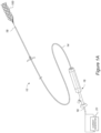
- Figure 1A illustrates a view of a treatment system 10 according to one or more embodiments of the present technology.
- the treatment system 10 can include an interventional element 100 coupled to a core assembly 18, and a delivery catheter 14 connected to a handle 16.
- the handle 16 shown provides proximal access to the core assembly 18 that engages the interventional element 100 at a distal end thereof.
- the delivery catheter 14 can be positioned coaxially over the core assembly 18.
- a current generator 20 can be coupled to a proximal portion of the core assembly 18 to provide an electrical current to the interventional element 100, as described in more detail below.
- the current generator 20 can include an electrical generator configured to output medically useful electrical current.
- Figures 1B and 1C are schematic views of different embodiments of the current generator 20.
- the current generator 20 can include a power source 22, a first terminal 24, a second terminal 26, and a controller 28.
- the controller 28 includes a processor 30 coupled to a memory 32 that stores instructions (e.g., in the form of software, code or program instructions executable by the processor or controller) for causing the power source 22 to deliver electric current according to certain parameters provided by the software, code, etc.
- the power source 22 of the current generator 20 may include a direct current power supply, an alternating current power supply, or a power supply switchable between a direct current and an alternating current.
- the current generator 20 can include a suitable controller that can be used to control various parameters of the energy output by the power source or generator, such as intensity, amplitude, duration, frequency, duty cycle, and polarity.
- the power supply 20 can provide a voltage of about 2 volts to about 28 volts and a current of about 0.5 mA to about 20 mA.
- Figure 1C illustrates another embodiment of the current generator 20, in which the controller 28 of Figure 1B is replaced with drive circuitry 34.
- the current generator 20 can include hardwired circuit elements to provide the desired waveform delivery rather than a software-based generator of Figure 1B .
- the drive circuitry 34 can include, for example, analog circuit elements (e.g., resistors, diodes, switches, etc.) that are configured to cause the power source 22 to deliver electric current via the first and second terminals 24, 26 according to the desired parameters.
- the drive circuitry 34 can be configured to cause the power source 22 to deliver periodic waveforms via the first and second terminals 24, 26.
- Some systems for endovascular delivery of electrical current require the use of a return electrode (and/or associated return conductive path) that is wholly separated from the delivery electrode (and/or associated delivery conductive path). This may involve, for example, the use of a return electrode embedded within a catheter wall, or a needle puncturing the patient to complete a conductive pathway.
- the present technology can provide, in one embodiment, an integrated core assembly that includes both a delivery electrode (and/or associated delivery conductive path) and a return electrode (and/or associated return conductive path) separated by an insulating material.
- electrically enhanced endovascular material removal can be facilitated by an electrode pair and associated delivery and return conductive paths provided within a treatment system, thereby avoiding the need to insert a needle into the patient to complete a circuit through the patient's tissue.
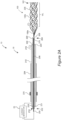
- FIG 2A is a side schematic cross-sectional view of the retrieval device shown in Figure 1 .
- the treatment system 10 includes the current generator 20, the core assembly 18, and the interventional element 100. As illustrated, the current generator 20 is electrically coupled to a proximal portion 202 of the core assembly 18, and the interventional element 100 is coupled to a distal portion 204 of the core assembly 18.
- the core assembly 18 can include multiple (e.g., two, or more than two) separate conductive paths or channels that provide electrical communication along the core assembly 18 with a corresponding number (e.g., two, or more than two) electrodes of the treatment system 10.
- the interventional element 100 can serve as one electrode (e.g., the delivery electrode) in electrical communication with one of the conductive paths of the core assembly 18.
- Another of the conductive paths of the core assembly 18 can be in electrical communication with another electrode (e.g., a return electrode) which can optionally form part of the core assembly 18.
- the various embodiments of the core assembly 18 can be sized for insertion into a bodily lumen, such as a blood vessel, and can be configured to push and pull a device such as the interventional element 100 along the bodily lumen.
- the core assembly 18 includes an elongate conductive shaft 206 and an elongate tubular member 212 having a lumen 214 through which the shaft 206 extends.
- the shaft 206 has a proximal portion 208 and a distal portion 210
- the tubular member 212 has a proximal portion 216 and a distal portion 218.
- Both the shaft 206 and the tubular member 212 are electrically conductive along their respective lengths.
- the positions of the shaft 206 and the tubular member 212 are fixed relative to one another.
- the shaft 206 is not slidable or rotatable with respect to the tubular member 212 such that the core assembly 18 can be pushed or pulled without relative movement between the shaft 206 and the tubular member 212 and/or other individual components of the core assembly 18.
- the shaft 206 can be a solid pushwire, for example a wire made of Nitinol or other metal or alloy.
- the shaft 206 may be thinner than would otherwise be required due to the additional structural column strength provided by the surrounding tubular member 212.
- the tubular member 212 is a hypotube.
- the tubular member 212 is a laser-cut hypotube having a spiral cut pattern along its length.
- the tubular member 212 can be made of stainless steel (e.g., 304 SS), Nitinol, and/or other alloy.
- the tubular member 212 can have a laser cut pattern to achieve the desired mechanical characteristics (e.g., column strength, flexibility, kink-resistance, etc.).
- the core assembly 18 can also include an adhesive or a mechanical coupler such as a crimped band or marker band 220 disposed at the distal end of the core assembly 18, and the marker band 220 can optionally couple the distal end of the core assembly 18 to the interventional element 100.
- the marker band 220 can be radiopaque, for example including platinum or other radiopaque material, thereby enabling visualization of the proximal end of the interventional element 100 under fluoroscopy.
- additional radiopaque markers can be disposed at various locations along the treatment system 10, for example along the shaft 206, the tubular member 212, or the interventional element 100 (e.g., at the distal end of the interventional element 100).
- the core assembly 18 can further include a proximal restraint 221 and/or a distal restraint 223 that are configured to maintain the relative positions of the elongate tubular member 212 and the shaft 206.
- the proximal restraint 221 is positioned at or near the proximal end of the tubular member 212
- the distal restraint 223 can be positioned at or near the distal end of the tubular member 212.
- the proximal and distal restraints 221, 223 comprise adhesive disposed radially around the shaft 206 such that the tubular member 208 cannot slide longitudinally with respect to the shaft 206.
- the proximal and/or distal restraints 221, 223 can be crimped bands or other suitable structures that limit longitudinal movement of the tubular member 212 with respect to the shaft 206.
- the proximal and/or distal restraints 221, 223 can be radiopaque.
- the core assembly 18 also includes a first insulating layer or material 222 extending between the shaft 206 and the surrounding tubular member 212.
- the first insulating material 222 can be, for example, PTFE (polytetrafluoroethylene or TEFLON TM ) or any other suitable electrically insulating coating (e.g., polyimide, oxide, ETFE based coatings, or any suitable dielectric polymer).
- the first insulating material 222 extends along substantially the entire length of the shaft 206.
- the first insulating material 222 separates and electrically insulates the shaft 206 and the tubular member 212 along the entire length of the tubular member 212.
- the first insulating material 222 does not cover the proximal-most portion of the shaft 206, providing an exposed region of the shaft 206 to which the current generator 20 can be electrically coupled.
- the first insulating material 222 terminates proximally at the proximal terminus of the shaft 206, and the current generator 20 can electrically couple to the shaft 206 at its proximal terminus, for example using a coaxial connector.
- the core assembly 18 can additionally include a second insulating layer or material 224 surrounding the tubular member 212 along at least a portion of its length.
- the second insulating layer 224 can be, for example, PTFE or any other suitable electrically insulative coating (e.g., polyimide, oxide, ETFE based coatings or any suitable dielectric polymer).
- the distal portion 218 of the tubular member 212 is not covered by the second insulating layer 224, leaving an exposed conductive surface at the distal portion 218.
- the length of the exposed distal portion 218 of the tubular member 212 can be between at least 1 and 10 inches, or between 2 inches and 8 inches, or between 3 and 7 inches, or between 4 and 6 inches, or about 5 inches.
- This exposed portion of the distal portion 218 of the tubular member 212 provides a return path for current supplied to the delivery electrode (e.g. the entirety or a portion of the interventional element 100), as described in more detail below.
- the second insulating material 224 does not cover the proximal-most portion of the tubular member 212, providing an exposed region of the tubular member 212 to which the current generator 20 can be electrically coupled.
- the second insulating material 224 proximally terminates at the proximal end of the proximal terminus of the tubular member 212, and the current generator 20 can electrically couple to the tubular member 212 at its proximal terminus, for example using a coaxial connector.
- the core assembly 18 can also include a retraction marker 225 in the proximal portion 216 of the tubular member 212.
- the retraction marker 225 can be a visible indicator to guide a clinician when proximally retracting an overlying catheter with respect to the core assembly 18.
- the retraction marker 225 can be positioned such that when a proximal end of the overlying catheter is retracted to be positioned at or near the retraction marker 225, the distal portion 218 of the tubular member 212 is positioned distally beyond a distal end of the catheter. In this position, the exposed distal portion 218 of the tubular member 212 is exposed to the surrounding environment (e.g., blood, tissue, etc.), and can serve as a return electrode for the core assembly 18.
- the surrounding environment e.g., blood, tissue, etc.
- the proximal end 208 of the shaft 206 can be electrically coupled to the positive terminal of the current generator 20, and the proximal end of the tubular member 212 can be electrically coupled to the negative terminal of the current generator 20.
- the treatment system 10 provides an electrical circuit in which current flows from the positive terminal of the current generator 20, distally through the shaft 206, the interventional element 100, and the surrounding media (e.g., blood, tissue, thrombus, etc.) before returning back to the exposed distal portion 218 of the tubular member, proximally through the tubular member 212, and back to the negative terminal of the current generator 20.
- the current generator 20 can include a power source and either a processor coupled to a memory that stores instructions for causing the power source to deliver electric current according to certain parameters, or hardwired circuit elements configured to deliver electric current according to the desired parameters.
- the current generator 20 may be integrated into the core assembly 18 or may be removably coupled to the core assembly 18, for example via clips, wires, plugs or other suitable connectors. Particular parameters of the energy provided by the current generator 20 are described in more detail below with respect to Figures 4A-4D .
- the polarities of the current generator 20 can be switched, so that the negative terminal is electrically coupled to the shaft 206 and the positive terminal is electrically coupled to the tubular member 212.
- This can be advantageous when, for example, attempting to attract predominantly positively charged material to the interventional element 100, or when attempting to break up a clot rather than grasp it with an interventional element.
- alternating current (AC) signals may be used rather than DC. In certain instances, AC signals may advantageously help break apart a thrombus or other material.
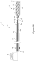
- the interventional element 100 can be a thrombectomy device having a low-profile configuration (not shown) when constrained within a delivery catheter (e.g., a microcatheter) and an expanded configuration for securing and/or engaging clot material or other obstructions within a blood vessel lumen (e.g., a cerebral blood vessel lumen) and/or for restoring blood flow within the blood vessel.
- the interventional element 100 has a proximal portion 100a coupled to the shaft 206 and a distal portion 100b.
- the interventional element 100 further includes an open cell framework or body 226 and a coupling region 228 extending proximally from the body 226.
- a distal portion 100b of the interventional element 100 can be generally tubular (e.g., cylindrical), and the proximal portion 100a of the interventional element 100 can taper proximally to the coupling region 228.
- the interventional element 100 can take any number of forms, for example a removal device, a thrombectomy device, a stent retriever, a stent, or other suitable medical device.
- the interventional element 100 is a mesh structure formed of a superelastic material (e.g., Nitinol) or other resilient or self-expanding material configured to self-expand when released from the delivery catheter.
- the interventional element can be a metallic or electrically conductive thrombectomy device having a number of struts and open spaces between the struts, and the struts and spaces can be situated along the longitudinal direction of the interventional element, the radial direction, or both.
- the interventional element 100 may be a stent and/or stent retriever, such as Medtronic's Solitaire TM Revascularization Device, Stryker Neurovascular's Trevo ® ProVue TM Stentriever, or other suitable devices.
- the interventional element 100 may include a plurality of braided filaments. Examples of suitable interventional elements 100 include any of those disclosed in U.S. Patent No.
- the interventional element 100 can be characterized by a working length WL, which can correspond to the region of the interventional element 100 configured to engage a thrombus or other material to be removed from a vessel lumen.
- the non-working length portion of the interventional element 100 i.e., proximal portion 100a
- a non-conductive material e.g., PTFE or other suitable non-conductive coating
- a distal region of the interventional element 100 may likewise be coated with a non-conductive material (e.g., PTFE or other suitable non-conductive coating), leaving only a central portion of the interventional element 100 having an exposed conductive surface.
- some or all of the interventional element 100 can be coated with a conductive material, for example gold or other suitable conductor.
- FIGS 3A-3D illustrate an example method of removing clot material from the lumen of a blood vessel V using the system 10 of the present technology.
- a guidewire 1 may be advanced through the clot material CM such that a distal terminus of the guidewire 1 is distal of the clot material CM.
- a delivery catheter 14 may be delivered over the guidewire 1 so that a distal portion of the delivery catheter 14 is positioned at or near the clot material CM.
- the delivery catheter 14 may be advanced over the guidewire 1 through the clot material CM such that a distal terminus of the delivery catheter 14 is distal of the clot material CM.
- the guidewire 1 may be withdrawn.
- the interventional element 100 may then be advanced through the delivery catheter 14 in a low-profile configuration until a distal terminus 101 of the interventional element 100 (shown schematically in Figure 3B ) is at or adjacent the distal terminus of the delivery catheter 14.
- the delivery catheter 14 may then be withdrawn proximally relative to the interventional element 100 to release the interventional element 100, thereby allowing the interventional element 100 to self-expand within the clot material CM.
- the interventional element 100 engages and/or secures the surrounding clot material CM, and in some embodiments may restore or improve blood flow through the clot material CM.
- the interventional element 100 may be expanded distal of the clot material CM such that no portion of the interventional element 100 is engaging the clot material CM while the interventional element 100 is in the process of expanding toward the vessel wall.
- the interventional element 100 is configured to expand into contact with the blood vessel wall, or the interventional element 100 may expand to a diameter that is less than that of the blood vessel lumen such that the interventional element 100 does not engage the entire circumference of the blood vessel wall.
- the interventional element 100 can grip the clot material CM, by virtue of its ability to mechanically interlock with the clot material CM as well as its ability to electrically attract, adhere, and/or attach to the clot material CM as a result of the delivery of electrical current to the interventional element 100.
- the current generator 20, which is electrically coupled to the proximal end 202 of the core assembly 18, can deliver an electrical signal to the interventional element 100 before or after the interventional element 100 has been released from the catheter 14 into the anatomical vessel V (e.g., an intracranial vessel) and/or expanded into the clot material CM.
- V e.g., an intracranial vessel
- the interventional element 100 can be left in place or manipulated within the vessel V for a desired time period while the electrical signal is being delivered. Positive current delivered to the interventional element 100 can attract negatively charged constituents of the clot material CM, thereby enhancing the grip of the interventional element 100 on the clot material CM. This allows the interventional element 100 to be used to retrieve the clot material CM with reduced risk of losing grip on the thrombus or a piece thereof, which can migrate downstream and cause additional vessel blockages in areas of the brain that are more difficult to reach.
- the clot material CM can be removed.
- the interventional element 100 with the clot material CM gripped thereby can be retracted (for example, along with the catheter 14) proximally.
- the catheter 14, interventional element 100, and associated clot material CM may then be withdrawn from the patient, optionally through one or more larger surrounding catheters.
- the interventional element 100 can grip the clot material CM electrically and/or electrostatically, e.g., via the application of current from a current generator as discussed herein.
- the interventional element 100 can maintain an enhanced or electrically and/or electrostatically enhanced grip on the clot material CM during retraction.
- the current generator 20 may cease delivery of electrical signals to the interventional element 100 prior to retraction of the interventional element 100 with respect to the vessel V.
- the interventional element 100 and clot material CM form a removable, integrated thrombus-device mass wherein the connection of the thrombus to the device is electrically enhanced, e.g. via the application of current as discussed herein.
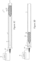
- Figures 4A-4D show various electrical waveforms for use with the retrieval devices of the present technology.
- the waveforms and other power delivery parameters disclosed herein can be used with the devices and methods described above with respect to Figures 1A-3D , the waveforms and other parameters are also applicable to other device configurations and techniques.
- the return electrode can be provided along the catheter wall, as a separate conductive member extending within the catheter lumen, as a needle electrode provided elsewhere in the body, etc.
- the power delivery parameters and waveforms can be beneficially employed to promote clot adhesion without damaging surrounding tissue.
- the waveforms and other power delivery parameters disclosed herein may be used for treating a cerebral or intracranial embolism, other applications and other embodiments in addition to those described herein are within the scope of the technology.
- the waveforms and power delivery parameters disclosed herein may be used to electrically enhance removal of emboli from body lumens other than blood vessels (e.g., the digestive tract, etc.) and/or may be used to electrically enhance removal of emboli from blood vessels outside of the brain (e.g., pulmonary blood vessels, blood vessels within the legs, etc.).
- While applying a continuous uniform direct current (DC) electrical signal to negatively charge the interventional element can improve its attachment to the thrombus, this can risk damage to surrounding tissue (e.g., ablation), and sustained current at a relatively high level may also be thrombogenic (i.e., may generate new clots).
- periodic waveforms For achieving effective clot-grabbing without ablating tissue or generating substantial new clots at the target site, periodic waveforms have been found to be particularly useful. Without wishing to be bound by theory, the clot-adhesion effect appears to be most closely related to the peak current of the delivered electrical signal.
- Periodic waveforms can advantageously provide the desired peak current without delivering excessive total energy or total electrical charge.
- Periodic, non-square waveforms in particular are well suited to deliver a desired peak current while reducing the amount of overall delivered energy or charge as compared to either uniform applied current or square waveforms.
- Figures 4A-4D illustrate various periodic waveforms that can be used with the devices and methods described above with respect to Figures 1A-3D , as well as with other devices and techniques. Electrical power can be delivered according to these waveforms as pulsed direct current.
- Figures 4A and 4B illustrate periodic square and triangular waveforms, respectively. These two waveforms have the same amplitude, but the triangular waveform is able to deliver the same peak current as the square waveform, with only half of the total charge delivered, and less total energy delivered.
- Figure 4C illustrates another pulsed-DC or periodic waveform which is a composite of a square waveform and a triangular waveform.
- FIG. 4C illustrates yet another non-square waveform, in this case a trapezoidal waveform in which "ramp-up" and “ramp-down" portions at the beginning and end of each pulse provide periods of reduced current compared to square waveforms.
- different non-square waveforms can be used, including a superposition of a square waveform with any non-square waveform, depending on the desired power delivery characteristics.
- the waveform shape (e.g., pulse width, duty cycle, amplitude) and length of time can each be selected to achieve desired power delivery parameters, such as overall electrical charge, total energy, and peak current delivered to the interventional element.
- the overall electrical charge delivered to the interventional element can be between about 30-1200 mC, or between about 120-600 mC.
- the total electrical charge delivered to the interventional element may be less than 600 mC, less than 500 mC, less than 400 mC, less than 300 mC, less than 200 mC, or less than 100 mC.
- the total energy delivered to the interventional element can be between about 0.75-24,000 mJ, or between about 120-24,000 mJ, or between about 120-5000 mJ. According to some embodiments, the total energy delivered to the interventional element may be less than 24,000 mJ, less than 20,000 mJ, less than 15,000 mJ, less than 10,000 mJ, less than 5,000 mJ, less than 4,000 mJ, less than 3,000 mJ, less than 2000 mJ, less than 1,000 mJ, less than 900 mJ, less than 800 mJ, less than 700 mJ, less than 600 mJ, less than 500 mJ, less than 400 mJ, less than 300 mJ, or less than 200 mJ, or less than 120 mJ, or less than 60 mJ, or less than 48 mJ, or less than 30 mJ, or less than 12 mJ, or less than 6 mJ, or less than 1.5 mJ.
- the peak current delivered can be between about 0.5-20 mA, or between about 0.5-5 mA. According to some embodiments, the peak current delivered may be greater than 0.5 mA, greater than 1 mA, greater than 1.5 mA, greater than 2 mA, greater than 2.5 mA, or greater than 3 mA.
- the duration of power delivery is another important parameter that can be controlled to achieve the desired clot-adhesion effects without damaging tissue at the target site or generating new clots.
- the total energy delivery time can be no more than 1 minute, no more than 2 minutes, no more than 3 minutes, no more than 4 minutes, or no more than 5 minutes. According to some embodiments, the total energy delivery time may be less about 30 seconds, less than about 1 minute, less than about 90 seconds, or less than about 2 minutes.
- the "total energy delivery time" refers to the time period during which the waveform is supplied to the interventional element (including those periods of time between pulses of current).
- the duty cycle of the applied electrical signal can also be selected to achieve the desired clot-adhesion characteristics without ablating tissue or promoting new clot formation.
- the duty cycle can be between about 5% about 99% or between about 5% to about 20%.
- the duty cycle may be about 10%, about 20%, about 30%, about 40%, or about 50%.
- a constant current may be used, in which the duty cycle is 100%.
- a lower time or current may be used to avoid delivering excess total energy to the target site.
- Table 1 presents a range of values for power delivery parameters of different waveforms.
- a resistance of 1 kohm and a frequency of 1 kHz for the Square, Triangle, and Composite conditions
- the Constant conditions represent a continuous and steady current applied for the duration, i.e. 100% duty cycle.
- the Peak Current 1 column represents the peak current for the corresponding waveform.
- the Peak Current 2 column indicates the peak current of the second portion of the waveform. For example, referring back to Figure 4C , Peak Current 1 would correspond to the current at the top of the triangular portion of the waveform, while Peak Current 2 would correspond to the current at the top of the square portion of the waveform.
- the periodic waveforms achieve higher peak currents with lower overall charge delivered than the corresponding Constant conditions.
- a peak current of 20 mA corresponds to a total energy delivered of 24,000 mJ
- condition Square 3 delivers a peak current of 20 mA with a total energy of only 4,800 mJ.
- Conditions Triangle 2 and Composite 1 similarly deliver lower total energy while maintaining a peak current of 20 mA. Since clot-adhesion appears to be driven by peak current, these periodic waveforms can therefore offer improved clot adhesion while reducing the risk of damaging tissue at the target site or promoting new clot formation.
- Table 1 also indicates that the Triangle and Composite conditions achieve higher peak currents with lower overall charge delivered than the corresponding Square conditions.
- condition Square 3 has a peak current of 20 mA and a total charge delivered of 240 mC
- condition Triangle 2 has a peak current of 20 mA but a total charge delivered of only 120 mC
- condition Composite 1 has a peak current of 20 mA and a total charge delivered of only 144 mC.
- these non-square waveforms provide additional benefits by delivering desirable peak current while reducing the overall charge delivered to the target site.
- Table 1 represents a series of waveforms with a single frequency (1 kHz)
- the frequency of the pulsed-DC waveforms can be controlled to achieve the desired effects.
- the frequency of the waveform can be between 1 Hz and 1 MHz, between 1Hz and 1 kHz, or between 500 Hz to 1 kHz.
Applications Claiming Priority (3)
| Application Number | Priority Date | Filing Date | Title |
|---|---|---|---|
| US15/838,230 US10709463B2 (en) | 2017-12-11 | 2017-12-11 | Electrically enhanced retrieval of material from vessel lumens |
| US15/838,214 US11058444B2 (en) | 2017-12-11 | 2017-12-11 | Electrically enhanced retrieval of material from vessel lumens |
| PCT/US2018/064676 WO2019118321A1 (en) | 2017-12-11 | 2018-12-10 | Electrically enhanced retrieval of material from vessel lumens |
Publications (3)
| Publication Number | Publication Date |
|---|---|
| EP3723633A1 EP3723633A1 (en) | 2020-10-21 |
| EP3723633A4 EP3723633A4 (en) | 2021-08-18 |
| EP3723633B1 true EP3723633B1 (en) | 2024-04-10 |
Family
ID=66820617
Family Applications (1)
| Application Number | Title | Priority Date | Filing Date |
|---|---|---|---|
| EP18888795.4A Active EP3723633B1 (en) | 2017-12-11 | 2018-12-10 | Device for electrically enhanced retrieval of material from vessel lumens |
Country Status (5)
| Country | Link |
|---|---|
| EP (1) | EP3723633B1 (ja) |
| JP (1) | JP7254081B2 (ja) |
| CN (1) | CN111542279B (ja) |
| IL (1) | IL275154A (ja) |
| WO (1) | WO2019118321A1 (ja) |
Families Citing this family (4)
| Publication number | Priority date | Publication date | Assignee | Title |
|---|---|---|---|---|
| US20220287765A1 (en) * | 2021-03-15 | 2022-09-15 | Covidien Lp | Medical treatment system |
| US11963713B2 (en) * | 2021-06-02 | 2024-04-23 | Covidien Lp | Medical treatment system |
| US20220387051A1 (en) * | 2021-06-02 | 2022-12-08 | Covidien Lp | Medical treatment system |
| US20220409258A1 (en) * | 2021-06-25 | 2022-12-29 | Covidien Lp | Current generator for a medical treatment system |
Citations (3)
| Publication number | Priority date | Publication date | Assignee | Title |
|---|---|---|---|---|
| US20100168739A1 (en) * | 2008-12-31 | 2010-07-01 | Ardian, Inc. | Apparatus, systems, and methods for achieving intravascular, thermally-induced renal neuromodulation |
| US20100174309A1 (en) * | 2008-05-19 | 2010-07-08 | Mindframe, Inc. | Recanalization/revascularization and embolus addressing systems including expandable tip neuro-microcatheter |
| WO2016007388A1 (en) * | 2014-07-09 | 2016-01-14 | Boston Scientific Scimed, Inc. | Medical retrieval devices and methods |
Family Cites Families (19)
| Publication number | Priority date | Publication date | Assignee | Title |
|---|---|---|---|---|
| US6190382B1 (en) * | 1998-12-14 | 2001-02-20 | Medwaves, Inc. | Radio-frequency based catheter system for ablation of body tissues |
| DE10233085B4 (de) | 2002-07-19 | 2014-02-20 | Dendron Gmbh | Stent mit Führungsdraht |
| WO2009014883A1 (en) * | 2007-07-20 | 2009-01-29 | Boston Scientific Scimed, Inc. | Power supply using time varying signal for electrolytically detaching implantable device |
| WO2009021071A2 (en) * | 2007-08-06 | 2009-02-12 | Henson Michael R | Thrombectomy system and method |
| US8066757B2 (en) | 2007-10-17 | 2011-11-29 | Mindframe, Inc. | Blood flow restoration and thrombus management methods |
| US20110301506A1 (en) * | 2007-12-14 | 2011-12-08 | Kim Volz | Ultrasound pulse shaping |
| US8940003B2 (en) | 2008-02-22 | 2015-01-27 | Covidien Lp | Methods and apparatus for flow restoration |
| US20090318994A1 (en) * | 2008-06-19 | 2009-12-24 | Tracee Eidenschink | Transvascular balloon catheter with pacing electrodes on shaft |
| US10028782B2 (en) * | 2008-11-03 | 2018-07-24 | Magneto Thrombectomy Solutions Ltd. | Method and apparatus for thrombus dissolution/thrombectomy by an electrode catheter device |
| US20110130756A1 (en) * | 2009-12-01 | 2011-06-02 | Everson Jr David C | Vasculature device |
| US9039749B2 (en) | 2010-10-01 | 2015-05-26 | Covidien Lp | Methods and apparatuses for flow restoration and implanting members in the human body |
| WO2013082032A1 (en) * | 2011-11-28 | 2013-06-06 | Mazar Scott T | Steerable guide wire with pressure sensor |
| US9833252B2 (en) * | 2013-03-15 | 2017-12-05 | Microvention, Inc. | Multi-component obstruction removal system and method |
| US8715314B1 (en) * | 2013-03-15 | 2014-05-06 | Insera Therapeutics, Inc. | Vascular treatment measurement methods |
| US20140364896A1 (en) * | 2013-06-07 | 2014-12-11 | Abott Cardiovascular Systems, Inc. | Device, system, and method for thrombus retrieval |
| GB201418474D0 (en) * | 2014-10-17 | 2014-12-03 | Creo Medical Ltd | Electrosurgical apparatus |
| CN107405160B (zh) * | 2015-03-02 | 2020-08-11 | 柯惠有限合伙公司 | 血管介入系统 |
| MX2018003943A (es) * | 2015-09-30 | 2018-11-09 | Ethicon Llc | Técnicas de protección para generador para generar de manera digital formas de onda de señal eléctrica ultrasónica y electroquirúrgica. |
| GB2545484A (en) * | 2015-12-18 | 2017-06-21 | Cook Medical Technologies Llc | Electrochemical protection of conducting circuit in the body of a patient |
-
2018
- 2018-12-10 EP EP18888795.4A patent/EP3723633B1/en active Active
- 2018-12-10 WO PCT/US2018/064676 patent/WO2019118321A1/en unknown
- 2018-12-10 JP JP2020531482A patent/JP7254081B2/ja active Active
- 2018-12-10 CN CN201880079914.8A patent/CN111542279B/zh active Active
-
2020
- 2020-06-05 IL IL275154A patent/IL275154A/en unknown
Patent Citations (3)
| Publication number | Priority date | Publication date | Assignee | Title |
|---|---|---|---|---|
| US20100174309A1 (en) * | 2008-05-19 | 2010-07-08 | Mindframe, Inc. | Recanalization/revascularization and embolus addressing systems including expandable tip neuro-microcatheter |
| US20100168739A1 (en) * | 2008-12-31 | 2010-07-01 | Ardian, Inc. | Apparatus, systems, and methods for achieving intravascular, thermally-induced renal neuromodulation |
| WO2016007388A1 (en) * | 2014-07-09 | 2016-01-14 | Boston Scientific Scimed, Inc. | Medical retrieval devices and methods |
Also Published As
| Publication number | Publication date |
|---|---|
| EP3723633A4 (en) | 2021-08-18 |
| EP3723633A1 (en) | 2020-10-21 |
| JP7254081B2 (ja) | 2023-04-07 |
| CN111542279B (zh) | 2024-03-05 |
| CN114343791A (zh) | 2022-04-15 |
| CN111542279A (zh) | 2020-08-14 |
| IL275154A (en) | 2020-07-30 |
| JP2021505283A (ja) | 2021-02-18 |
| WO2019118321A1 (en) | 2019-06-20 |
Similar Documents
| Publication | Publication Date | Title |
|---|---|---|
| US11944334B2 (en) | Electrically enhanced retrieval of material from vessel lumens | |
| US11832836B2 (en) | Electrically enhanced retrieval of material from vessel lumens | |
| US10987117B2 (en) | Electrically enhanced retrieval of material from vessel lumens | |
| US11523838B2 (en) | Retrieval of material from corporeal lumens | |
| US11395668B2 (en) | Electrically enhanced retrieval of material from vessel lumens | |
| US11612430B2 (en) | Electrically enhanced retrieval of material from vessel lumens | |
| EP3723633B1 (en) | Device for electrically enhanced retrieval of material from vessel lumens | |
| US20210177427A1 (en) | Electrically enhanced retrieval of material from vessel lumens | |
| US11963713B2 (en) | Medical treatment system | |
| EP4209185A1 (en) | Electrically enhanced retrieval of material from vessel lumens | |
| CN114343791B (zh) | 从血管内腔电增强取出材料 |
Legal Events
| Date | Code | Title | Description |
|---|---|---|---|
| STAA | Information on the status of an ep patent application or granted ep patent |
Free format text: STATUS: THE INTERNATIONAL PUBLICATION HAS BEEN MADE |
|
| PUAI | Public reference made under article 153(3) epc to a published international application that has entered the european phase |
Free format text: ORIGINAL CODE: 0009012 |
|
| STAA | Information on the status of an ep patent application or granted ep patent |
Free format text: STATUS: REQUEST FOR EXAMINATION WAS MADE |
|
| 17P | Request for examination filed |
Effective date: 20200512 |
|
| AK | Designated contracting states |
Kind code of ref document: A1 Designated state(s): AL AT BE BG CH CY CZ DE DK EE ES FI FR GB GR HR HU IE IS IT LI LT LU LV MC MK MT NL NO PL PT RO RS SE SI SK SM TR |
|
| AX | Request for extension of the european patent |
Extension state: BA ME |
|
| DAV | Request for validation of the european patent (deleted) | ||
| DAX | Request for extension of the european patent (deleted) | ||
| A4 | Supplementary search report drawn up and despatched |
Effective date: 20210715 |
|
| RIC1 | Information provided on ipc code assigned before grant |
Ipc: A61B 17/221 20060101AFI20210709BHEP Ipc: A61B 17/22 20060101ALI20210709BHEP Ipc: A61B 17/3207 20060101ALI20210709BHEP Ipc: A61B 18/00 20060101ALI20210709BHEP Ipc: A61F 2/966 20130101ALI20210709BHEP Ipc: A61B 18/14 20060101ALI20210709BHEP |
|
| STAA | Information on the status of an ep patent application or granted ep patent |
Free format text: STATUS: EXAMINATION IS IN PROGRESS |
|
| 17Q | First examination report despatched |
Effective date: 20230118 |
|
| GRAP | Despatch of communication of intention to grant a patent |
Free format text: ORIGINAL CODE: EPIDOSNIGR1 |
|
| STAA | Information on the status of an ep patent application or granted ep patent |
Free format text: STATUS: GRANT OF PATENT IS INTENDED |
|
| RIC1 | Information provided on ipc code assigned before grant |
Ipc: A61B 18/00 20060101ALN20231129BHEP Ipc: A61B 90/00 20160101ALN20231129BHEP Ipc: A61B 18/14 20060101ALI20231129BHEP Ipc: A61F 2/966 20130101ALI20231129BHEP Ipc: A61B 17/3207 20060101ALI20231129BHEP Ipc: A61B 17/221 20060101AFI20231129BHEP |
|
| RIC1 | Information provided on ipc code assigned before grant |
Ipc: A61B 18/00 20060101ALN20231204BHEP Ipc: A61B 90/00 20160101ALN20231204BHEP Ipc: A61B 18/14 20060101ALI20231204BHEP Ipc: A61F 2/966 20130101ALI20231204BHEP Ipc: A61B 17/3207 20060101ALI20231204BHEP Ipc: A61B 17/221 20060101AFI20231204BHEP |
|
| INTG | Intention to grant announced |
Effective date: 20231222 |
|
| GRAS | Grant fee paid |
Free format text: ORIGINAL CODE: EPIDOSNIGR3 |
|
| GRAA | (expected) grant |
Free format text: ORIGINAL CODE: 0009210 |
|
| STAA | Information on the status of an ep patent application or granted ep patent |
Free format text: STATUS: THE PATENT HAS BEEN GRANTED |
|
| AK | Designated contracting states |
Kind code of ref document: B1 Designated state(s): AL AT BE BG CH CY CZ DE DK EE ES FI FR GB GR HR HU IE IS IT LI LT LU LV MC MK MT NL NO PL PT RO RS SE SI SK SM TR |
|
| REG | Reference to a national code |
Ref country code: GB Ref legal event code: FG4D |
|
| REG | Reference to a national code |
Ref country code: CH Ref legal event code: EP |