EP3723397B1 - Orchestration de canal adaptatif - Google Patents
Orchestration de canal adaptatif Download PDFInfo
- Publication number
- EP3723397B1 EP3723397B1 EP20166810.0A EP20166810A EP3723397B1 EP 3723397 B1 EP3723397 B1 EP 3723397B1 EP 20166810 A EP20166810 A EP 20166810A EP 3723397 B1 EP3723397 B1 EP 3723397B1
- Authority
- EP
- European Patent Office
- Prior art keywords
- channels
- configuration
- channel
- cellular communication
- communication apparatus
- Prior art date
- Legal status (The legal status is an assumption and is not a legal conclusion. Google has not performed a legal analysis and makes no representation as to the accuracy of the status listed.)
- Active
Links
Images


Classifications
-
- H—ELECTRICITY
- H04—ELECTRIC COMMUNICATION TECHNIQUE
- H04B—TRANSMISSION
- H04B7/00—Radio transmission systems, i.e. using radiation field
- H04B7/14—Relay systems
- H04B7/15—Active relay systems
- H04B7/185—Space-based or airborne stations; Stations for satellite systems
- H04B7/18502—Airborne stations
- H04B7/18506—Communications with or from aircraft, i.e. aeronautical mobile service
-
- H—ELECTRICITY
- H04—ELECTRIC COMMUNICATION TECHNIQUE
- H04L—TRANSMISSION OF DIGITAL INFORMATION, e.g. TELEGRAPHIC COMMUNICATION
- H04L5/00—Arrangements affording multiple use of the transmission path
- H04L5/0001—Arrangements for dividing the transmission path
- H04L5/0003—Two-dimensional division
- H04L5/0005—Time-frequency
- H04L5/0007—Time-frequency the frequencies being orthogonal, e.g. OFDM(A) or DMT
- H04L5/001—Time-frequency the frequencies being orthogonal, e.g. OFDM(A) or DMT the frequencies being arranged in component carriers
-
- H—ELECTRICITY
- H04—ELECTRIC COMMUNICATION TECHNIQUE
- H04B—TRANSMISSION
- H04B17/00—Monitoring; Testing
- H04B17/30—Monitoring; Testing of propagation channels
- H04B17/309—Measuring or estimating channel quality parameters
-
- H—ELECTRICITY
- H04—ELECTRIC COMMUNICATION TECHNIQUE
- H04B—TRANSMISSION
- H04B7/00—Radio transmission systems, i.e. using radiation field
- H04B7/14—Relay systems
- H04B7/15—Active relay systems
- H04B7/185—Space-based or airborne stations; Stations for satellite systems
-
- H—ELECTRICITY
- H04—ELECTRIC COMMUNICATION TECHNIQUE
- H04L—TRANSMISSION OF DIGITAL INFORMATION, e.g. TELEGRAPHIC COMMUNICATION
- H04L5/00—Arrangements affording multiple use of the transmission path
- H04L5/003—Arrangements for allocating sub-channels of the transmission path
- H04L5/0058—Allocation criteria
- H04L5/006—Quality of the received signal, e.g. BER, SNR, water filling
-
- H—ELECTRICITY
- H04—ELECTRIC COMMUNICATION TECHNIQUE
- H04W—WIRELESS COMMUNICATION NETWORKS
- H04W16/00—Network planning, e.g. coverage or traffic planning tools; Network deployment, e.g. resource partitioning or cells structures
- H04W16/14—Spectrum sharing arrangements between different networks
-
- H—ELECTRICITY
- H04—ELECTRIC COMMUNICATION TECHNIQUE
- H04W—WIRELESS COMMUNICATION NETWORKS
- H04W24/00—Supervisory, monitoring or testing arrangements
- H04W24/08—Testing, supervising or monitoring using real traffic
-
- H—ELECTRICITY
- H04—ELECTRIC COMMUNICATION TECHNIQUE
- H04W—WIRELESS COMMUNICATION NETWORKS
- H04W36/00—Hand-off or reselection arrangements
- H04W36/06—Reselecting a communication resource in the serving access point
-
- H—ELECTRICITY
- H04—ELECTRIC COMMUNICATION TECHNIQUE
- H04W—WIRELESS COMMUNICATION NETWORKS
- H04W36/00—Hand-off or reselection arrangements
- H04W36/24—Reselection being triggered by specific parameters
- H04W36/30—Reselection being triggered by specific parameters by measured or perceived connection quality data
- H04W36/304—Reselection being triggered by specific parameters by measured or perceived connection quality data due to measured or perceived resources with higher communication quality
-
- H—ELECTRICITY
- H04—ELECTRIC COMMUNICATION TECHNIQUE
- H04W—WIRELESS COMMUNICATION NETWORKS
- H04W36/00—Hand-off or reselection arrangements
- H04W36/24—Reselection being triggered by specific parameters
- H04W36/32—Reselection being triggered by specific parameters by location or mobility data, e.g. speed data
- H04W36/322—Reselection being triggered by specific parameters by location or mobility data, e.g. speed data by location data
-
- H—ELECTRICITY
- H04—ELECTRIC COMMUNICATION TECHNIQUE
- H04W—WIRELESS COMMUNICATION NETWORKS
- H04W4/00—Services specially adapted for wireless communication networks; Facilities therefor
- H04W4/02—Services making use of location information
- H04W4/021—Services related to particular areas, e.g. point of interest [POI] services, venue services or geofences
-
- H—ELECTRICITY
- H04—ELECTRIC COMMUNICATION TECHNIQUE
- H04W—WIRELESS COMMUNICATION NETWORKS
- H04W4/00—Services specially adapted for wireless communication networks; Facilities therefor
- H04W4/30—Services specially adapted for particular environments, situations or purposes
- H04W4/40—Services specially adapted for particular environments, situations or purposes for vehicles, e.g. vehicle-to-pedestrians [V2P]
- H04W4/42—Services specially adapted for particular environments, situations or purposes for vehicles, e.g. vehicle-to-pedestrians [V2P] for mass transport vehicles, e.g. buses, trains or aircraft
-
- H—ELECTRICITY
- H04—ELECTRIC COMMUNICATION TECHNIQUE
- H04W—WIRELESS COMMUNICATION NETWORKS
- H04W52/00—Power management, e.g. Transmission Power Control [TPC] or power classes
- H04W52/04—Transmission power control [TPC]
- H04W52/18—TPC being performed according to specific parameters
- H04W52/24—TPC being performed according to specific parameters using SIR [Signal to Interference Ratio] or other wireless path parameters
- H04W52/243—TPC being performed according to specific parameters using SIR [Signal to Interference Ratio] or other wireless path parameters taking into account interferences
-
- H—ELECTRICITY
- H04—ELECTRIC COMMUNICATION TECHNIQUE
- H04B—TRANSMISSION
- H04B17/00—Monitoring; Testing
- H04B17/10—Monitoring; Testing of transmitters
- H04B17/101—Monitoring; Testing of transmitters for measurement of specific parameters of the transmitter or components thereof
-
- H—ELECTRICITY
- H04—ELECTRIC COMMUNICATION TECHNIQUE
- H04B—TRANSMISSION
- H04B17/00—Monitoring; Testing
- H04B17/10—Monitoring; Testing of transmitters
- H04B17/11—Monitoring; Testing of transmitters for calibration
- H04B17/12—Monitoring; Testing of transmitters for calibration of transmit antennas, e.g. of the amplitude or phase
-
- H—ELECTRICITY
- H04—ELECTRIC COMMUNICATION TECHNIQUE
- H04B—TRANSMISSION
- H04B17/00—Monitoring; Testing
- H04B17/10—Monitoring; Testing of transmitters
- H04B17/15—Performance testing
- H04B17/18—Monitoring during normal operation
-
- H—ELECTRICITY
- H04—ELECTRIC COMMUNICATION TECHNIQUE
- H04B—TRANSMISSION
- H04B7/00—Radio transmission systems, i.e. using radiation field
- H04B7/14—Relay systems
- H04B7/15—Active relay systems
- H04B7/185—Space-based or airborne stations; Stations for satellite systems
- H04B7/18502—Airborne stations
- H04B7/18504—Aircraft used as relay or high altitude atmospheric platform
-
- H—ELECTRICITY
- H04—ELECTRIC COMMUNICATION TECHNIQUE
- H04L—TRANSMISSION OF DIGITAL INFORMATION, e.g. TELEGRAPHIC COMMUNICATION
- H04L41/00—Arrangements for maintenance, administration or management of data switching networks, e.g. of packet switching networks
- H04L41/08—Configuration management of networks or network elements
- H04L41/0803—Configuration setting
-
- H—ELECTRICITY
- H04—ELECTRIC COMMUNICATION TECHNIQUE
- H04W—WIRELESS COMMUNICATION NETWORKS
- H04W16/00—Network planning, e.g. coverage or traffic planning tools; Network deployment, e.g. resource partitioning or cells structures
- H04W16/02—Resource partitioning among network components, e.g. reuse partitioning
- H04W16/10—Dynamic resource partitioning
-
- H—ELECTRICITY
- H04—ELECTRIC COMMUNICATION TECHNIQUE
- H04W—WIRELESS COMMUNICATION NETWORKS
- H04W24/00—Supervisory, monitoring or testing arrangements
- H04W24/02—Arrangements for optimising operational condition
-
- H—ELECTRICITY
- H04—ELECTRIC COMMUNICATION TECHNIQUE
- H04W—WIRELESS COMMUNICATION NETWORKS
- H04W24/00—Supervisory, monitoring or testing arrangements
- H04W24/10—Scheduling measurement reports ; Arrangements for measurement reports
-
- H—ELECTRICITY
- H04—ELECTRIC COMMUNICATION TECHNIQUE
- H04W—WIRELESS COMMUNICATION NETWORKS
- H04W72/00—Local resource management
- H04W72/04—Wireless resource allocation
- H04W72/044—Wireless resource allocation based on the type of the allocated resource
- H04W72/0453—Resources in frequency domain, e.g. a carrier in FDMA
-
- H—ELECTRICITY
- H04—ELECTRIC COMMUNICATION TECHNIQUE
- H04W—WIRELESS COMMUNICATION NETWORKS
- H04W72/00—Local resource management
- H04W72/20—Control channels or signalling for resource management
- H04W72/23—Control channels or signalling for resource management in the downlink direction of a wireless link, i.e. towards a terminal
-
- H—ELECTRICITY
- H04—ELECTRIC COMMUNICATION TECHNIQUE
- H04W—WIRELESS COMMUNICATION NETWORKS
- H04W72/00—Local resource management
- H04W72/50—Allocation or scheduling criteria for wireless resources
- H04W72/54—Allocation or scheduling criteria for wireless resources based on quality criteria
- H04W72/541—Allocation or scheduling criteria for wireless resources based on quality criteria using the level of interference
-
- H—ELECTRICITY
- H04—ELECTRIC COMMUNICATION TECHNIQUE
- H04W—WIRELESS COMMUNICATION NETWORKS
- H04W72/00—Local resource management
- H04W72/50—Allocation or scheduling criteria for wireless resources
- H04W72/54—Allocation or scheduling criteria for wireless resources based on quality criteria
- H04W72/542—Allocation or scheduling criteria for wireless resources based on quality criteria using measured or perceived quality
-
- H—ELECTRICITY
- H04—ELECTRIC COMMUNICATION TECHNIQUE
- H04W—WIRELESS COMMUNICATION NETWORKS
- H04W76/00—Connection management
- H04W76/10—Connection setup
-
- H—ELECTRICITY
- H04—ELECTRIC COMMUNICATION TECHNIQUE
- H04W—WIRELESS COMMUNICATION NETWORKS
- H04W84/00—Network topologies
- H04W84/005—Moving wireless networks
Definitions
- the present disclosure relates to wireless communication.
- the present disclosure relates to a wireless communication apparatus and method for adaptively orchestrating channels.
- channel planning can be performed in order to plan the locations of base stations, the channel/bandwidth allocations of those base stations, and the power of the transmissions in order to provide good coverage.
- Such planning takes into account a number of different factors such as other transmitters in the local area, the placement of buildings, and the available bandwidths in which transmission can occur (and at which powers).
- Such planning relies on the static nature of these factors - buildings are unlikely to move and transmitters are unlikely to stop transmitting. If such changes do occur, then the entire plan might have to be redesigned from scratch. Such a system is therefore ill-suited to a situation in which flexibility is required.
- EP 3346784 considers a carrier selection method and apparatus in carrier aggregation technique.
- US 2009/047971 relates to configuring radio resource allocation and scheduling mobile station mechanisms for frequency reuse in cellular OFDMA systems.
- US 2009/318138 describes a system and method for in-flight wireless communication.
- EP 3062446 considers a dynamic link adaption and/or dynamic allocation of communication resources of a communication system based on external interference information receives from external interference information sources.
- a cellular communication apparatus comprising: antenna circuitry; a transceiver to receive or transmit a signal using the antenna circuitry on a chosen channel of a portion of a radio spectrum, wherein the portion of the radio spectrum is divided into one or more channels, including the chosen channel, each occupying a bandwidth of the portion of the radio spectrum; control circuitry to dynamically change a configuration of the one or more channels of the radio spectrum; and communication circuitry to communicate the configuration of the one or more channels of the radio spectrum to one or more items of user equipment.
- the cellular communication apparatus which could take the form of a base station to which items of user equipment communicate, uses an antenna to perform communication.
- the antenna is capable of communicating on a number of channels.
- the channels are each defined as a portion of available radio spectrum. This could be defined as, for instance, a centre frequency and a width of the channel, or could be defined as a start frequency and end frequency of the channel.
- a first channel may occur at a centre frequency of 2428.3 MHz and have a width of 5 MHz
- a second channel may have a centre frequency of 2455 MHz and have a width of 10 MHz
- a third channel may have a start frequency of 2474 MHz and an end frequency of 2475.6.
- the channels may be non-contiguous and/or nonoverlapping. Usually, some channels are noisier (having higher levels of noise) than others, depending on the amount of interference. Such interference can come from other transmitters, which may intentionally be transmitting within the same frequency or could be transmitting in a nearby frequency that inherently 'leak' interfering signals into adjacent frequencies.
- the cellular communication apparatus and user equipment can compensate for the interference by increasing the transmission power or reception sensitivity of particular channels. However, there is typically a maximum total power across all channels that can be applied and therefore a network operator must be selective in how channels are configured. Such channel configurations can be derived by performing network planning.
- the cellular communication apparatus includes control circuitry that dynamically (e.g. on-demand) changes the configuration of the channels.
- the revised configuration can then be communicated to the user equipment using, e.g. a special control channel, in order to overcome changes in demand and/or interference in the network.
- the control circuitry is adapted to dynamically change the configuration of the one or more channels of the radio spectrum in response to unsolicited interference.
- Unsolicited interference may be considered to be interference that was not originally anticipated. For instance, unsolicited interference could come about as a consequence of a nearby transmitter transmitting into reserved areas of the radio spectrum or by unplanned levels of anticipated radio communications in the area.
- the control circuitry is able to dynamically (e.g. on-demand) change the configuration in order to respond to such interference. This saves the need for a new planning exercise being performed in response to interference that could arbitrarily appear and disappear.
- control circuitry is adapted to dynamically change the configuration of the one or more channels of the radio spectrum autonomously.
- the behaviour of the control circuitry in these examples is such that the control circuitry is able to dynamically change the configuration by itself (e.g. without human interaction).
- Such configuration change may be achieved by the application of one or more algorithms that analyse interference in the radio spectrum, either from the perspective of the cellular communication apparatus and/or the user equipment, and respond accordingly.
- control circuitry is adapted to dynamically change the configuration of the one or more channels of the radio spectrum in a decentralised manner. In some embodiments, is possible to take a number of different radio transmitters and receivers into account when determining how the configuration should be changed.
- the transceiver is adapted to receive a noise profile from the one or more items of user equipment; and the control circuitry is adapted to dynamically change the configuration of the one or more channels of the radio spectrum based on the noise profile from the one or more items of user equipment.
- the noise profile of an item of user equipment may be considered to be the interference levels received by that user equipment at different parts of the radio spectrum.
- the cellular communication apparatus could end up modifying the configuration in order to adjust the channels in such a way that some of the items of user equipment would be forced to communicate with the cellular communication apparatus on a channel that is, to those items of user equipment, noisy. This would result in lower levels of communication between the cellular communication apparatus and the items of user equipment and would consequently cause a decrease in the throughput that could be achieved. Furthermore, by considering more than one of the items of user equipment, it is possible to derive a configuration that will be generally acceptable to a large proportion of the network.
- control circuitry is adapted to dynamically change the configuration of the one or more channels of the radio spectrum such that the one or more channels occupy areas of bandwidth having more favourable radio conditions than prior to the configuration being changed.
- the goal of dynamically changing of the configuration of the one or more channels may be to provide more favourable radio conditions than before the configuration was changed. Improved radio conditions can lead to faster, more accurate communication as well as the communication of more information in a shorter time. This can therefore lead to lower latency communication.
- the more favourable radio conditions comprise a lower noise than prior to the configuration being changed.
- the noise level may be defined as the background signal strength at a particular frequency, which may be caused by background radiation as well as other transmitters.
- interference could derive from low-quality transmitters that ostensibly transmit at a particular frequency but cause a "leakage" of signal into other neighbouring frequencies.
- other interference could occur from other transmitters legitimately transmitting at the same frequency.
- Such transmitters may, for instance, belong to different radio systems that are not part of the current network.
- the more favourable radio conditions comprise a higher throughput than prior to the configuration being changed.
- Throughput can be considered to be the amount of data that is transferred in a space of time. More favourable radio conditions could therefore correspond with a higher throughput being achieved than was possible if the previous (unmodified) configuration.
- the more favourable radio conditions are for a majority of the one or more items of user equipment.
- the revised configuration could result in more favourable radio conditions for one item of user equipment (or the cellular communication apparatus) or for a minority of the items of user equipment (possibly including the cellular communication apparatus), in other embodiments, the more favourable conditions are for a majority of the items of user equipment (possibly including the cellular communication apparatus).
- the more favourable radio conditions occur for all of the items of user equipment. That is to say that other items of user equipment outside the majority may experience similar radio conditions, or may experience worse radio conditions than before the configuration was modified.
- the more favourable radio conditions are an average of radio conditions of the one or more items of user equipment. Rather than considering a number of the items of user equipment that obtain more favourable radio conditions, one could instead consider the average affect of applying the modified configuration. In such examples, the more favourable radio conditions result in more favourable radio conditions on average for each of the items of user equipment. Consequently, a small number of items of user equipment could achieve a very large increase in radio conditions, while other items of user equipment could experience a small decrease in radio conditions, therefore providing an overall improvement when these results are averaged.
- the average could be calculated. For instance, the average could be calculated as an average improvement or an average performance.
- the average could also be calculated as a mean, median, mode or other type of average.
- the goal may be to improve the experience of poorly performing user equipment other than to improve the overall average experience.
- the goal may be to benefit the items of user equipment that already perform well by benefiting user equipment that is more likely to make effective use of the favourable radio conditions that are achieved. In practice, which of these goals is pursued will be dependent on the priorities of the network operator.
- the cellular communication apparatus comprises: processing circuitry to perform dynamic programming to determine the configuration of the one or more channels of the radio spectrum achieving the more favourable radio conditions.
- Dynamic programming can be considered to be a technique in which a large "optimisation problem" is broken down into a number of subtasks. The solution to each of those subtasks may be used in order to determine the overall solution to the "optimisation problem". By breaking down the problem in this manner, the number of different possibilities that may be considered can be dramatically reduced.
- dynamic programming is effective due to the number of combinations of channel modifications that can take place. By considering the problem in stages, it is possible to vastly reduce the number of candidate solutions to be considered. The use of dynamic programming is therefore especially well suited to the problem of channel configuration.
- a number of stages of the dynamic programming corresponds with a number of the one or more channels; and each stage of the dynamic programming is directed towards obtaining the more favourable radio conditions by considering the addition of one of the one or more channels.
- each of the stages of the dynamic programming problem responds to the consideration of how to add a further channel to the new configuration.
- this solution may be derived 'backwards'. For example, if the new configuration is to have a maximum of n channels assigned to it then the first stage may consider how channel n is to be added to the configuration depending on all the different options for the configuration with n-1 channels allocated. For each option, the throughput (for instance) can be assessed to determine how the addition of the channel changes the situation.
- a second stage of the process then considers how channel n-1 is to be added to the configuration depending on all the different options for the configuration with n-2 channels allocated. For each possible way to add channel n-1, the best way of adding channel n is known from the first stage. Consequently, the second stage will reveal the best way of allocating channels n and n-1 for each possible starting state.
- This process can be worked backwards until one considers, in an n'th stage, what the best first channel to add will be. The process can then be 'backtracked'. That is, knowing what the best first channel to add is then indicates what the best second channel to add is, and so on.
- the number of stages corresponds with the number of channels to be added because in some cases, the answer is trivial. For instance, if there are five possible locations to place a channel and five channels must be added then there is no need for dynamic programming to be performed - all channels are activated. Similarly, regardless of the number of possible locations for channels to be placed, if only one channel must be activated the all the different possibilities can be directly compared.
- the dynamic programming is performed a number of times corresponding to a maximum number of the one or more channels that can be supported.
- the process described above determines a configuration of n channels. However, as the number of channels increases, the amount of power available for other channels decreases. Therefore, it is necessary to consider different numbers of channels in case a smaller number of channels (operating at a higher power) are able to achieve a better configuration. In these embodiments, therefore, the above process is repeated for a number of times corresponding to the maximum number of channels that can be activated.
- control circuitry is adapted to dynamically change the configuration by changing a centre frequency of at least one of the channels.
- a centre frequency of a channel may be considered to be the point at which the channels lies in the radio spectrum.
- a channel can be defined by using a reference point (a centre frequency, start frequency, and end frequency) and an indication of a size (bandwidth) of the channel.
- control circuitry is adapted to dynamically change the configuration by changing a bandwidth of at least one of the channels.
- the bandwidth of a channel may be considered to be the other factor that defines the location of a channel. This could be a simple width of the channel, but could also be defined by an end frequency of the channel, for instance.
- control circuitry is adapted to dynamically change the configuration by changing a power of at least one of the channels.
- Some channels can also be configured to transmit at different powers to different channels.
- many transmitters may have a maximum transmission power across all channels. For instance, a transmitter may be permitted to transmit at a total of 24dBm. This transmission power must be spread across all channels on which the transmitter transmits. Consequently, the transmitter may be able to transmit on a single channel at high power or a number of channels at a lower power.
- control circuitry is adapted to dynamically change a number of the channels. It will be appreciated that the changing of the number of channels on which the cellular communication apparatus can transmit also involve the changing of the centre frequency, power, and bandwidth of the newly added channels. As discussed above, an increase in the number of channels is likely (if all the power is being used) to result in other channels having a power reduced. In general, an increase in the number of channels can also result in the overhead of managing those channels.
- the transceiver is to transmit the configuration using the antenna circuitry.
- the configuration of the one or more channels may be transmitted using the antenna circuitry. This could occur, for instance, by using a special control channel on which configuration data is transmitted.
- the configuration could be transmitted in another manner - for instance using another form of wireless communication, for instance.
- the communication circuitry comprises the transceiver.
- the communication circuitry may be the transceiver itself.
- the same transceiver is used to both transmit the data on the one or more channels and also to transmit the configuration of the one or more channels to items of user equipment.
- FIG. 1 illustrates a cellular communication apparatus 100 in accordance with some embodiments.
- the apparatus 100 which takes the form of a cellular base station, includes antenna circuitry 130, which could take the form of an antenna or an antenna array for instance.
- the antenna circuitry 130 is used by a transceiver 110 in order to transmit or receive signals. Each signal is broadcast on a particular 'channel' - a block of the radio spectrum.
- a transceiver 110 is used by a transceiver 110 in order to transmit or receive signals.
- Each signal is broadcast on a particular 'channel' - a block of the radio spectrum.
- particular protocols and/or legislation may place controls on the transmission power, size, and frequency bounds at which transmissions occur.
- certain areas of the radio spectrum could be reserved for commercial or governmental use or could be completely open. Areas of the radio spectrum could be subject to particular restrictions (e.g. maximum transmission powers), which is particularly common in areas of the radio spectrum that are open.
- the LTE cellular specification restricts the bandwidth
- the configuration of radio channels is calculated according to the above restrictions by performing simulation and modelling. This could take into account the locations of base stations, the types of antenna used, known interferers and interference patterns, buildings, signal propagation, and so on. In practice, however, changes to any of these factors can have a significant detrimental effect on the network. For instance, if a new entity starts transmitting in the local area then this could create unanticipated or unsolicited interference. The placement of new buildings could inhibit signal propagation. The use of poorly designed antenna systems could cause interference in the form of 'leakage'. The disruption (e.g.
- the cellular communication apparatus 100 communicates with another cellular communication apparatus in the form of a plane 170.
- the plane 170 starts in a relatively isolated area 160 where interference is low.
- the plane 170 passes over a city 150 in which interference is much greater due to the prevalence of radio equipment (such as from Wi-Fi, Bluetooth, etc.).
- the cellular communication apparatus 100 of the present embodiments responds to this situation by dynamically changing the radio channel configuration. For instance, if the movement of the plane 170 to a location over a city 150 renders the existing channels unusable then the cellular communication apparatus 100 could create another channel in a part of the radio spectrum that is less congested in order to improve communication with the plane 170.
- the control of the channel configuration is achieved by control circuitry 120. Having changed the configuration of the channels, the new configuration can be transmitted by communication circuitry 140.
- the communication circuitry could, for instance, transmit the configuration via another form of communication (e.g. a satellite connection) or could use (or be) the antenna circuitry 130 itself, e.g. using a special defined control channel.
- the modification to the channel configuration can be autonomous. In particular, it does not necessitate human intervention.
- the present techniques may also be decentralised. In particular, the configuration is determined by considering the situation from not only the cellular communication apparatus 100, but also at the devices that communicate with the cellular communication apparatus 100 such as the plane 170.
- the present technique is not limited to fixing a reduction of network quality.
- the present technique can also be used to dynamically change or improve the quality or efficiency of the network where opportunities arise, as will be demonstrated with respect to the following figures.
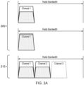
- FIG. 2A illustrates the manner in which the channel configuration can be adapted to handle changes in network demand.
- a first configuration 200 shows a single channel (Channel 1).
- the usage of the channel (Usage 1) is approximately half of the channel's capacity.
- the configuration is updated to a revised configuration 210.
- a second channel (Channel 2) is created, the second channel being defined at a bandwidth after the end of the bandwidth used by the first channel (Channel 1). Users can then be split between the two channels.
- a third channel (Channel 3) can be created and so on.
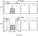
- Figure 2B shows the use of the present technique in responding to unsolicited/unplanned interference.
- a first configuration 230 four channels of equal power are provided.
- interference occurs at a bandwidth that partially eclipses the first and second channels.
- Such interference could originate, for instance, from increased background noise, or could occur from a third party radio transmission.
- the interference limits the effective capacity of the network.
- legitimate transmissions (those made or desired by the network operator) may have to transmit at a higher power in order to be heard over the interference.
- Retransmissions may be necessary, which increases the latency of the network and also reduces its capacity.
- scheduling may have to take place outside the time when the interference occurs - thereby limiting the available transmission time and the effective capacity of the network.
- the present technique reconfigures the channel configuration to provide a revised configuration 240.
- the bandwidth of the first channel 260a is reduced 260b and the bandwidth the second channel 260c is reduced 260d.
- the centre-point (the central frequency) of the first channel 250a is moved 250b and the centre-point of the second channel 250c is moved 250d.
- the new configuration 240 moves the channels so that they avoid the frequencies at which interference occurs.
- FIG. 2C shows how the present technique can be used to boost transmission power.
- the signal to noise ratio (SNR) for channel 1 can be improved. This allows not only communication with devices that are further away from the cellular communication apparatus 100 (due to attenuation occurring over a longer distance) but also decreases the error rate in radio transmission - leading to fewer retransmissions and greater throughput.
- Figure 2D illustrates an extension to this idea in which the bandwidth of the first channel is also decreased in order to allow further power boosting.
- This power boost comes at the cost of decreased bandwidth, which may limit the number of users that can simultaneously communicate with the cellular communication apparatus 100.
- Figure 3 illustrates how the "noise profile" for different devices 300, 310 that communicate with the cellular communication apparatus 100 may differ.
- Figure 3 illustrates a thermal noise (shown by a dashed line) for both the first device 300 and the second device 310.
- the thermal noise line is approximately the same for both devise, since this is largely caused by, e.g. background radiation, which may be expected to be relatively similar within a local region.
- the interference line shown as a solid line
- Both of the devices experience low interference at the top end of the radio spectrum and so both devices share a common channel (1) 320.
- the first device 300 Since the interference is low for both devices 300, 310, the power for that channel 320 is also low - a high transmission power is not necessitated by the interference.
- the first device 300 experiences a dip in interference at the middle of the radio spectrum, resulting in a mid-sized channel (2) 330 in the middle of the spectrum of moderate power.
- the first device 300 also experiences a small, narrow dip in interference at the bottom end of the spectrum, resulting in the creation of a narrow channel (3) 340 created with high power - the high power being necessary to overcome the higher interference than is experienced at the other channels 320, 330.
- the second device 310 has a mostly different noise profile. Since the interference is low for the top end of the spectrum, the second device 310 also makes us of one of the channels (1) 320. The second device 310 experiences a high interference at the frequency associated with the other channels 330, 340 established for the first device 300. Consequently, these channels are not used by the second device 310. Instead, a channel (4) 350 is created for the second device 310 at a point in the middle of the spectrum where the interference in the radio spectrum sharply drops briefly. This channel (4) 350 is able to use a mid-level of power owing to its small bandwidth. Finally, the first device 310 experiences a low level of interference for a large part of the low end of the spectrum. This results in a wide channel (5) 360 being created. Given that the channel is wide and that the interference is low, the power usage for this channel 310 is also low.
- the cellular communication apparatus 100 therefore provides a channel configuration using five channels.
- the channels are configured in order to take advantage of the points in the spectrum where interference is low for each of the first device 300 and the second device 310. In this way, both devices 300, 310 are able to communicate with the cellular communication apparatus 100 efficiently.
- the determination of the channel configuration can be decentralised and can take into account the noise profiles of different devices 300, 310 in the network, rather than simply relying on the noise profile at the cellular communication apparatus 100.
- the noise profile of each of the devices 300, 310 can be determined by those devices performing frequency scanning at allowed frequencies. At each permitted frequency, each device 300, 310 can determine the amount of interference experienced. This information can then be provided to the cellular communication apparatus 100, which determines the channel configuration using the noise profile information from each device.
- a strategy might be to create channels of high power to take advantage of low interference, thereby achieving high throughput.
- a strategy might be to create channels of high power to overcome high interference, thereby compensating for devices that might not otherwise be able to communicate well with the cellular communication apparatus 100.
- the purpose of selecting and configuring the channels may be considered to be one of creating more favourable radio conditions (e.g. a higher throughput or achieving less noise/interference) during communication.
- Such conditions may be considered for one of the devices 300, 310, for a subset of the devices, or for all of the devices.
- the strategy used might seek to favour one device 300, 310 at the cost of all others, or might seek to improve the situation for as many devices 300, 310 as possible.
- the strategy that is employed will depend on the nature of the network and the priorities of the network operator.
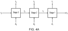
- each stage builds up the solution to cover the desired number of channels, with up to one channel being added at each stage. For example, a (max) four channel solution is made up from four stages.
- the process works backwards.
- the first stage considers the addition of the fourth channel for each way in which three channels can be allocated.
- the second stage considers the addition of the third channel for each way in which two channels can be added, and so on.
- Figure 4A illustrates a three stage process (e.g. in which the final solution uses three channels).
- the inputs and outputs to each stage can be defined as follows:
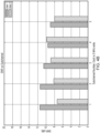
- Figure 4B illustrates the signal to noise (SNR) ratio that can be achieved by each of two users (devices) for each of the five bandwidth blocks.
- SNR signal to noise
- channel allocated are represented as a series of boxes.
- a filled (black) box indicates that the channel has been allocated/enabled
- an unfilled (white) box indicates that the channel has not been allocated/enabled and is available.
- a filled black box, followed by a white box, followed by a black box, followed by a white box, followed by a black box would therefore be represented by the bit string '10101' .
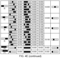
- Figure 4C illustrates the set of candidates available at each stage for the creation of a single channel.
- each channel must have a contiguous bandwidth of 5 MHz (one block), 10 MHz (two blocks), or 20 MHz (four blocks).
- Figure 4C illustrates the throughput that is achieved when each of these configurations is used. That is to say that when the third configuration is applied, in which a single channel of 5 MHz is created using the third block of bandwidth '00100', a throughput of 64.0500 Mbps is achieved among all devices communicating with the cellular communication apparatus 100.
- a single channel of 10 MHz is created using blocks one and two '11000', a throughput of 64.5500 Mbps is achieved. This information can be determined by measurement at the cellular communication apparatus 100.
- Figure 4D shows the application of the first stage of the process.
- the first stage considers how a third channel can be allocated. It therefore considers all possible configurations of the first two channels - these are shown in the column "Available Resources". For each of these initial configurations, there remain a number of possible ways in which the third channel can be allocated using the current resource usage. These are illustrated, for each possible option for the "Available Resources” in the "Candidate Decisions" column. A “Candidate Decision” cannot use part of the bandwidth that has been allocated to another channel.
- the "Candidate Throughput" for each of the "Candidate Decisions” is derived using the table shown in Figure 4C , which shows the throughput that can be achieved from a single channel.
- the column “Maximum Throughput” shows the maximum throughput that can be achieved from any of the “Candidate Decisions” for a given option of "Available Resources”.
- the column “Optimal Decision” shows the corresponding configuration of third channel that provides the “Maximum Throughput” and the “Resource Usage” is the combination of the "Available Resources” and “Optimal Decision”.
- the row 400 in which the current resources are defined as the bit string '10010'. That is to say that a first channel uses the first block of 5 MHz, and a second channel uses the 4 th block of 5 MHz.
- the row 400 considers a candidate solution in which the third channel uses the second block.
- the throughput that can be achieved is 66.1000 Mbps. That is to say that Figure 4C shows that the channel '01000' achieves 66.1000 MHz. In this case, this is the best throughput that can be achieved from the candidates that are available.
- the resulting resource usage that would occur if this option was selected is shown in the column as "Resource Usage". It is represented by the bit string '11010', and is achieved by combining the bit strings '10010', which is the starting resource usage and '01000', which is the resource usage of the channel that yields the best throughput.
- Figure 4D therefore shows for each possible allocation of two channels (of which there are 23 possibilities), what the resulting best option would be for the allocation of the third channel.
- Figure 4E shows the application of the second stage of the process.
- the second stage considers how the second channel can be allocated. It therefore considers all possible configurations of the first channel - shown in the "Available Resources” column.
- the “Candidate Decisions” column shows the possible allocations for the second channel, given the available radio spectrum. It will be appreciated that there are generally more candidate decisions in the second stage than in the first stage because in the second stage there is more likely to be more unused bandwidth.
- the "Candidate Throughput” column shows the throughput that can be achieved for each "Candidate Decision” and is again calculated using Figure 4C .
- the "Resource Usage” column is again calculated by combining the "Candidate Decision" with the "Available Resources".
- the "Optimum Throughput from next stage” column considers the maximum throughput that can be achieved if using the "Resource Usage” as a candidate in the first stage.
- the "Candidate Throughput for Stages #1 and #2” column then combines the throughput achieved for the "Candidate Decision” in stage 2 together with the maximum throughput that can be achieved with the resource usage, using stage 1.
- the column “Maximum Throughput for Stages #1 and #2” then determines the maximum throughput from each of these candidates and the "Optimal Decision” column illustrates the "Candidate Decision” that leads to that optimal throughput for stages 1 and 2.
- Figure 4E therefore shows for each possible allocation of one channel (of which there are 11 possibilities), what the resulting best option would be for the allocation of the second and third channels.
- each option for the second channel is considered, and the resulting resource usage is analysed to determine how those resources could be best allocated.
- the calculated throughput for each candidate is the sum of the throughput that can be achieved with the allocation of the second channel and the best throughput that can be achieved with what would then be left (using the results of the first stage).
- Figure 4F shows the application of the third stage of the process.
- the third stage considers how the first channel can be allocated.
- this stage since only three channels are allocated, all of the resources are available for allocation. There is only, therefore, a single starting state (shown in the "Available Resources” column) of '00000'.
- Each of the "Candidate Decisions” considers a different possibility for the allocation of the first channel. It will be appreciated that these and the "Candidate Throughputs" match the possibilities enumerated in Figure 4C .
- the "Resources Usage” column illustrates the resources that are available depending on which candidate decision is selected.
- the "Optimum Throughput from next stage” is calculated with reference to the second stage. In particular, given each possibility for the "Resource Usage", the second stage is referenced to determine the maximum throughput that can be achieved.
- the "Candidate Throughput for stages #1, #2, and #3” column is the sum of the column “Optimum Throughput from next stage” and “Candidate Throughput”. It therefore represents the total throughput that can be achieved by considering the throughput achieved for a particular candidate and the maximum throughput that can be achieved using the resource usage.
- the "Maximum Throughput for Stages #1, #2, and #3” looks at the maximum of these values, and the "Optimal Decision” indicates which of these options produces the best (e.g. maximum) throughput.
- the maximum throughput that can be achieved from any candidate is 196.7600, which is achieved when starting with the selecting of the channel '01000'.
- Figure 4F therefore shows for each possible choice of the first channel (of which there are 11 possibilities), what the resulting best option would be for the allocation of the first, second, and third channels.
- each option for the first channel is considered, and the resulting resources usage is analysed to determine how those resources could be best allocated.
- the calculated throughput for each candidate is the sum of the throughput that can be achieved with the allocation of the first channel and the best throughput that can be achieved with what would then be left (using the results of the second stage).
- a process of "backtracking" can then be used to establish the overall best result. From Figure 4F we can see that the optimal decision is the channel '01000'. From Figure 4E , we can see that, given the allocation '01000', the best choice is the channel '00100', which means that the resource usage would be '01100'. From Figure 4D , we can see that given a resource usage of '01100', the best option is the channel '00010'. Consequently, the best overall resource usage is ⁇ 01110', for a total throughput of 196.7500 Mbps. This therefore represents the ideal configuration of channels - three channels, each of 5 MHz, in the positions '01110'.
- the above process can clearly be extended to remove some of the initial assumptions at the cost of introducing further candidates. For instance, the current process assumes that all channels are allocated an equal amount of power. However, this is not necessarily the case and one could elect to use a first channel at three times the power of a second channel. Similarly, for convenience the above example assumed that there were five blocks of bandwidth available in which channels could be created. However, there could be more blocks of bandwidth available in more locations. Clearly, however, the finer the granularity of the channel centre frequency, the higher the number of candidates to be considered, and the more time consuming the process will take to execute.
- Figure 5 illustrates a flow chart 500.
- the value n is set to 0 and the value N is set to the maximum number of channels that can be allocated or created as supported by the hardware, protocol and any legislative restrictions.
- a loop begins. If n is less than N then at step 540, the configuration for up to n channels is determined as shown above, for instance.
- the above flowchart describes a method in which the optimal configuration is selected for each possible maximum number of channels.
- a configuration having two channels may be superior to a configuration having three channels and that this would not be picked up when determining the configuration for three channels (where each channel uses 1/3 of the available power).
- the process illustrate in Figure 5 will determine this, however, since it includes explicitly determining a configuration having two channels in which each channel uses 1/2 the available power rather than 1/3 of the available power.
- the superior configuration will therefore be picked up this manner.
- the above technique therefore performs dynamic programming a number of times equal to the maximum number of channels that can be created - each time considering an end solution having a different number of channels.
- the process is executed to provide a one channel solution, then a two channel solution, then a three channel solution, then a four channel solution, then a five channel solution.
- the best solution e.g. achieving the highest throughput is then selected as the selected channel configuration.
- FIG. 6 shows a flowchart 600 that illustrates a method of cellular communication in accordance with some embodiments.
- a signal is transmitted or received on a chosen channel, which is a portion of a radio spectrum.
- the configuration of the channels within the radio spectrum is changed. This change occurs dynamically, e.g. in response to unsolicited or unexpected interference occurring.
- the new configuration is communicated to one or more items of user equipment. The communication could take place using the main antenna system of the cellular apparatus or could take place in another form altogether.
- the above description illustrates how cellular equipment can collaborate in order to determine the configuration of channels.
- the width, location, and number of channels can be dynamically changed in order to respond to interference that may be experienced by one or more items of equipment or to respond to changes in demand.
- Several methods of calculating a configuration have been demonstrated, including a process that operates using dynamic programming. In this way, the allocation of the channels can be configured to achieve better radio conditions than might otherwise be possible and changes can be made to the configuration without the need for complex modelling of base stations, receivers, interferers, etc.
- the words “configured to" are used to mean that an element of an apparatus has a configuration able to carry out the defined operation.
- a “configuration” means an arrangement or manner of interconnection of hardware or software.
- the apparatus may have dedicated hardware which provides the defined operation, or a processor or other processing device may be programmed to perform the function.
- Configured to does not imply that the apparatus element needs to be changed in any way in order to provide the defined operation.
Landscapes
- Engineering & Computer Science (AREA)
- Signal Processing (AREA)
- Computer Networks & Wireless Communication (AREA)
- Aviation & Aerospace Engineering (AREA)
- Quality & Reliability (AREA)
- Physics & Mathematics (AREA)
- Astronomy & Astrophysics (AREA)
- General Physics & Mathematics (AREA)
- Electromagnetism (AREA)
- Mobile Radio Communication Systems (AREA)
Claims (14)
- Appareil de communication cellulaire (100) comprenant :un circuit d'antenne (130) ;un émetteur-récepteur (110) pour recevoir ou transmettre un signal à l'aide du circuit d'antenne sur un canal choisi dans une partie du spectre radioélectrique, la partie du spectre radioélectrique étant divisée en un ou plusieurs canaux, y compris le canal choisi, chacun occupant une largeur de bande de la partie du spectre radioélectrique ;un circuit de commande (120) pour modifier dynamiquement la configuration des un ou plusieurs canaux du spectre radioélectrique ; etun circuit de communication (140) pour communiquer la configuration des un ou plusieurs canaux du spectre radioélectrique à un ou plusieurs équipements d'utilisateur, dans lequel :
le circuit de commande est adapté pour modifier dynamiquement la configuration des un ou plusieurs canaux du spectre radioélectrique en réponse à des interférences non sollicitées. - Appareil de communication cellulaire selon l'une quelconque des revendications précédentes, dans lequel : le circuit de commande est adapté pour modifier dynamiquement la configuration des un ou plusieurs canaux du spectre radioélectrique de manière autonome.
- Appareil de communication cellulaire selon la revendication 2, dans lequel :
le circuit de commande est adapté pour modifier dynamiquement la configuration des un ou plusieurs canaux du spectre radioélectrique de manière décentralisée. - Appareil de communication cellulaire selon l'une quelconque des revendications précédentes, dans lequel :l'émetteur-récepteur est adapté pour recevoir un profil de bruit provenant des un ou plusieurs équipements d'utilisateur ; etle circuit de commande est adapté pour modifier dynamiquement la configuration des un ou plusieurs canaux du spectre radioélectrique sur la base du profil de bruit provenant des un ou plusieurs équipements d'utilisateur.
- Appareil de communication cellulaire selon l'une quelconque des revendications précédentes, dans lequel :
le circuit de commande est adapté pour modifier dynamiquement la configuration des un ou plusieurs canaux du spectre radio de sorte que les un ou plusieurs canaux occupent des zones de la largeur de bande présentant des conditions radio plus favorables qu'avant la modification de la configuration. - Appareil de communication cellulaire selon la revendication 5, dans lequel :les conditions radio plus favorables comprennent un ou plusieurs des éléments suivants :un bruit plus faible qu'avant la modification de la configuration, etun débit plus élevé qu'avant la modification de la configuration.
- Appareil de communication cellulaire selon l'une quelconque des revendications 5 à 6, dans lequel :
les conditions radio les plus favorables concernent une majorité des un ou plusieurs équipements d'utilisateur. - Appareil de communication cellulaire selon l'une quelconque des revendications 5 à 6, dans lequel :
les conditions radio les plus favorables sont une moyenne des conditions radio d'un ou de plusieurs équipements d'utilisateur. - Appareil de communication cellulaire selon l'une quelconque des revendications 5 à 8, comprenant :
un circuit de traitement permettant d'effectuer une programmation dynamique afin de déterminer la configuration des un ou plusieurs canaux du spectre radioélectrique permettant d'obtenir les conditions radio les plus favorables. - Appareil de communication cellulaire selon la revendication 9, dans lequel :le nombre d'étapes de la programmation dynamique correspond au nombre des un ou plusieurs canaux ; etchaque étape de la programmation dynamique est orientée vers l'obtention de conditions radio plus favorables en considérant l'ajout d'un ou de plusieurs canaux.
- Appareil de communication cellulaire selon la revendication 10, dans lequel :
la programmation dynamique est exécutée un nombre de fois correspondant à un nombre maximum des un ou plusieurs canaux pouvant être pris en charge. - Appareil de communication cellulaire selon l'une quelconque des revendications précédentes, dans lequel :
le circuit de commande est adapté pour modifier dynamiquement la configuration en changeant un ou plusieurs des éléments suivants :une fréquence centrale d'au moins un des canaux,une largeur de bande d'au moins un des canaux,la puissance d'au moins un des canaux, etle nombre de canaux. - Appareil de communication cellulaire selon l'une quelconque des revendications précédentes, dans lequel :
l'émetteur-récepteur doit transmettre la configuration à l'aide du circuit d'antenne. - Procédé de communication cellulaire comprenant les étapes suivantes :recevoir ou transmettre un signal à l'aide d'un circuit d'antenne sur un canal choisi d'une partie du spectre radioélectrique, la partie du spectre radioélectrique étant divisée en un ou plusieurs canaux, y compris le canal choisi, chacun occupant une largeur de bande de la partie du spectre radioélectrique ;modifier dynamiquement une configuration des un ou plusieurs canaux du spectre radioélectrique ; etcommuniquer la configuration des un ou plusieurs canaux du spectre radioélectrique à un ou plusieurs équipements d'utilisateur,la configuration des un ou plusieurs canaux du spectre radioélectrique étant modifiée en réponse à des interférences non sollicitées.
Applications Claiming Priority (2)
| Application Number | Priority Date | Filing Date | Title |
|---|---|---|---|
| GBGB1905222.4A GB201905222D0 (en) | 2019-04-12 | 2019-04-12 | Air-to-ground (ATG) communication technologies |
| GB2003168.8A GB2583831B (en) | 2019-04-12 | 2020-03-05 | Adaptive channel orchestration |
Publications (2)
| Publication Number | Publication Date |
|---|---|
| EP3723397A1 EP3723397A1 (fr) | 2020-10-14 |
| EP3723397B1 true EP3723397B1 (fr) | 2024-12-18 |
Family
ID=66809934
Family Applications (4)
| Application Number | Title | Priority Date | Filing Date |
|---|---|---|---|
| EP20166798.7A Active EP3723396B1 (fr) | 2019-04-12 | 2020-03-30 | Modems à distance |
| EP20166810.0A Active EP3723397B1 (fr) | 2019-04-12 | 2020-03-30 | Orchestration de canal adaptatif |
| EP20167161.7A Active EP3723392B1 (fr) | 2019-04-12 | 2020-03-31 | Configuration de la zone desservie par une station de base fournissant une communication sans fil |
| EP20168984.1A Active EP3723398B1 (fr) | 2019-04-12 | 2020-04-09 | Commutation de support adaptatif |
Family Applications Before (1)
| Application Number | Title | Priority Date | Filing Date |
|---|---|---|---|
| EP20166798.7A Active EP3723396B1 (fr) | 2019-04-12 | 2020-03-30 | Modems à distance |
Family Applications After (2)
| Application Number | Title | Priority Date | Filing Date |
|---|---|---|---|
| EP20167161.7A Active EP3723392B1 (fr) | 2019-04-12 | 2020-03-31 | Configuration de la zone desservie par une station de base fournissant une communication sans fil |
| EP20168984.1A Active EP3723398B1 (fr) | 2019-04-12 | 2020-04-09 | Commutation de support adaptatif |
Country Status (3)
| Country | Link |
|---|---|
| US (5) | US11146448B2 (fr) |
| EP (4) | EP3723396B1 (fr) |
| GB (5) | GB201905222D0 (fr) |
Families Citing this family (5)
| Publication number | Priority date | Publication date | Assignee | Title |
|---|---|---|---|---|
| EP3857966B1 (fr) * | 2018-09-27 | 2024-02-21 | ZTE Corporation | Technologie d'accès inter-radio (rat) |
| GB201905222D0 (en) | 2019-04-12 | 2019-05-29 | Airspan Networks Inc | Air-to-ground (ATG) communication technologies |
| EP3941129B1 (fr) * | 2019-03-29 | 2024-09-11 | Huawei Technologies Co., Ltd. | Procédé et appareil de communication wi-fi |
| US11791971B2 (en) * | 2020-01-17 | 2023-10-17 | Qualcomm Incorporated | Component carrier group based bandwidth part switching |
| US11456521B2 (en) * | 2020-04-02 | 2022-09-27 | Softbank Corp. | Controlling antenna beam generation to compensate for motion of a high-altitude platform |
Family Cites Families (53)
| Publication number | Priority date | Publication date | Assignee | Title |
|---|---|---|---|---|
| KR100263036B1 (ko) * | 1996-11-20 | 2000-08-01 | 김영환 | 디지탈 케이블티브이 시스템의 원격제어장치 |
| US7180876B1 (en) | 2001-05-14 | 2007-02-20 | At&T Corp. | Mobile device having network interface selection |
| US9306657B2 (en) * | 2005-04-08 | 2016-04-05 | The Boeing Company | Soft handoff method and apparatus for mobile vehicles using directional antennas |
| US20070165526A1 (en) | 2006-01-14 | 2007-07-19 | Hyun Lee | Wireless QoS by hardware packet sizing, data rate modulation, and transmit power controlling based on the accumulated packet drop rate |
| US8243612B2 (en) * | 2007-08-01 | 2012-08-14 | Microsoft Corporation | Dynamic channel-width allocation in wireless networks |
| US8259601B2 (en) | 2007-10-16 | 2012-09-04 | Mediatek Inc. | Interference measurement mechanism for frequency reuse in cellular OFDMA systems |
| US8917207B2 (en) * | 2007-10-16 | 2014-12-23 | Livetv, Llc | Aircraft in-flight entertainment system having a multi-beam phased array antenna and associated methods |
| KR101472058B1 (ko) * | 2008-01-29 | 2014-12-16 | 삼성전자주식회사 | 채널 대역폭을 적응적으로 제어하는 통신 장치 및 통신방법 |
| US20090221302A1 (en) | 2008-02-28 | 2009-09-03 | Vesa Pekka Luiro | Method, apparatus and computer program for reverse load balancing for the provision of services to client devices |
| JP2009260635A (ja) | 2008-04-16 | 2009-11-05 | Mitsubishi Electric Corp | 端末局、基地局、無線通信システムおよび通信制御方法 |
| US20090318138A1 (en) | 2008-06-20 | 2009-12-24 | Honeywell International Inc. | System and method for in-flight wireless communication |
| NZ590777A (en) * | 2008-07-31 | 2012-11-30 | Genentech Inc | PYRIMIDINE COMPOUNDS, COMPOSITIONS AND METHODS OF USE FOR INHIBITING mTOR |
| US8290503B2 (en) * | 2009-02-01 | 2012-10-16 | Qualcomm Incorporated | Multichannel dynamic frequency selection |
| US20100329200A1 (en) | 2009-06-24 | 2010-12-30 | Industrial Tehnology Research Institute | Apparatus and method for allocating uplink resources |
| US8340677B2 (en) * | 2009-07-02 | 2012-12-25 | Futurewei Technologies, Inc. | System and method for semi-static downlink inter-cell interference coordination for wireless communications |
| US8503381B2 (en) | 2009-08-03 | 2013-08-06 | Lg Electronics Inc. | Apparatus and method for configuring radio connection in multiple component carrier system |
| US20110244860A1 (en) * | 2010-04-02 | 2011-10-06 | Chih-Hsiang Wu | Method of Changing Primary Component Carrier and Related Communication Device |
| US8381250B2 (en) * | 2010-08-11 | 2013-02-19 | Verizon Patent And Licensing Inc. | Customer premises equipment architecture for bundled services in a fixed broadband wireless installation |
| US20120263117A1 (en) * | 2011-04-13 | 2012-10-18 | Motorola Mobility, Inc. | Method and Apparatus to Adjust the Control Region of a Subframe for Reducing Interference Between Channels in Wireless Communication Systems |
| EP2710827B1 (fr) * | 2011-05-16 | 2019-02-27 | Telefonaktiebolaget LM Ericsson (publ) | Procédé et système concernant les interférences entre systèmes |
| US11190310B2 (en) * | 2011-09-26 | 2021-11-30 | Texas Instruments Incorporated | Method and apparatus for CSI feedback in CoMP (coordinated multi-point) systems |
| US20130114571A1 (en) * | 2011-11-07 | 2013-05-09 | Qualcomm Incorporated | Coordinated forward link blanking and power boosting for flexible bandwidth systems |
| US9072107B2 (en) * | 2012-01-11 | 2015-06-30 | Interdigital Patent Holdings, Inc. | Adaptive control channel |
| JP5981172B2 (ja) * | 2012-03-12 | 2016-08-31 | シャープ株式会社 | 無線通信システム、通信方法、基地局装置、および通信端末 |
| US9479321B2 (en) * | 2012-11-02 | 2016-10-25 | Telefonaktiebolaget L M Ericsson (Publ) | Flexible spectrum support in cellular wireless communications |
| EP2753003B1 (fr) * | 2013-01-08 | 2021-03-31 | Alcatel Lucent | Tête radio à distance et procédé pour une tête radio à distance |
| CN104219723B (zh) * | 2013-05-30 | 2019-08-27 | 南京中兴软件有限责任公司 | 一种基于载波聚合技术实现软切换的方法及基站、终端 |
| US9603074B2 (en) * | 2013-12-16 | 2017-03-21 | Apple Inc. | Systems and methods for carrier channel selection in carrier aggregation enabled networks |
| US9357402B2 (en) * | 2014-02-25 | 2016-05-31 | Microsoft Technology Licensing, Llc | Guard band usage for wireless data transmission |
| US9385803B2 (en) * | 2014-03-28 | 2016-07-05 | UBiQOMM, INC. | Provision of broadband access to airborne platforms |
| US9503247B2 (en) | 2014-05-21 | 2016-11-22 | Verizon Patent And Licensing Inc. | Carrier aggregation management |
| US9826448B2 (en) * | 2014-07-11 | 2017-11-21 | Qualcomm Incorporated | Handover management in air-to-ground wireless communication |
| BR112017006813A2 (pt) | 2014-10-07 | 2018-01-09 | Ericsson Telefon Ab L M | mobilidade em redes densas |
| EP3219140B1 (fr) | 2014-11-14 | 2020-07-08 | Interdigital Patent Holdings, Inc. | Procédés et procédures pour des mesures de canal et des mécanismes de rapport |
| US9628168B2 (en) | 2015-02-26 | 2017-04-18 | Space Systems/Loral, Llc | Dynamic link adaption and/or dynamic allocation of communication resources of a communication system based on external interference information received from external interference information sources |
| US10085266B1 (en) | 2015-02-26 | 2018-09-25 | Sprint Spectrum L.P. | Management of TTI bundling for carrier aggregated communications |
| EP3131211B1 (fr) | 2015-08-14 | 2019-10-09 | Industrial Technology Research Institute | Procédé de formation de faisceau dynamique et appareils associés l'utilisant |
| JP6541289B2 (ja) * | 2015-09-29 | 2019-07-10 | ホアウェイ・テクノロジーズ・カンパニー・リミテッド | キャリアアグリゲーション技術におけるキャリア選択方法およびデバイス |
| US10111152B2 (en) * | 2015-12-09 | 2018-10-23 | Telefonaktiebolaget Lm Ericsson (Publ) | Cell selection for airborne mobile cellular communications equipment |
| US10524255B2 (en) * | 2016-05-20 | 2019-12-31 | Lg Electronics Inc. | Method and apparatus for handling DC subcarrier in NR carrier in wireless communication system |
| US10028244B2 (en) * | 2016-07-06 | 2018-07-17 | Gogo Llc | Hyper-number portability |
| US10638394B2 (en) | 2016-09-07 | 2020-04-28 | Parallel Wireless, Inc. | Multi-stage handover |
| CN108141770B (zh) | 2016-09-09 | 2021-05-04 | 达闼机器人有限公司 | 终端移动性管理的方法、网络设备及终端 |
| WO2018045572A1 (fr) | 2016-09-09 | 2018-03-15 | 深圳前海达闼云端智能科技有限公司 | Procédé d'accès pour terminal et dispositif de réseau |
| US10334611B2 (en) * | 2016-09-22 | 2019-06-25 | Apple Inc. | Device, system, and method for carrier aware scheduling |
| WO2018113946A1 (fr) | 2016-12-21 | 2018-06-28 | Telefonaktiebolaget Lm Ericsson (Publ) | Indication d'état its |
| US11284300B2 (en) * | 2016-12-30 | 2022-03-22 | Comcast Cable Communications, Llc | Efficiently managing network traffic |
| US10237758B2 (en) * | 2017-01-19 | 2019-03-19 | Verizon Patent And Licensing Inc. | System and method for a usage category specific self-organizing network |
| ES2974322T3 (es) | 2017-05-04 | 2024-06-26 | Koninklijke Philips Nv | Comunicación intragrupo |
| SE1750614A1 (en) * | 2017-05-17 | 2018-11-18 | Icomera Ab | Communication system for aircrafts |
| WO2019060015A1 (fr) * | 2017-09-21 | 2019-03-28 | Sony Mobile Communications Inc. | Procédé et appareil de commande de canal d'ancrage |
| GB201905222D0 (en) | 2019-04-12 | 2019-05-29 | Airspan Networks Inc | Air-to-ground (ATG) communication technologies |
| US10693557B1 (en) * | 2019-03-26 | 2020-06-23 | Gogo Llc | Dual fidelity connectivity on-board a vehicle |
-
2019
- 2019-04-12 GB GBGB1905222.4A patent/GB201905222D0/en not_active Ceased
- 2019-10-17 GB GB1915033.3A patent/GB2583003B/en not_active Expired - Fee Related
- 2019-10-17 GB GB1915024.2A patent/GB2583153B/en active Active
-
2020
- 2020-03-03 GB GB2003024.3A patent/GB2586675B/en active Active
- 2020-03-05 GB GB2003168.8A patent/GB2583831B/en active Active
- 2020-03-24 US US16/827,970 patent/US11146448B2/en active Active
- 2020-03-24 US US16/828,821 patent/US11924703B2/en active Active
- 2020-03-30 EP EP20166798.7A patent/EP3723396B1/fr active Active
- 2020-03-30 EP EP20166810.0A patent/EP3723397B1/fr active Active
- 2020-03-31 EP EP20167161.7A patent/EP3723392B1/fr active Active
- 2020-03-31 US US16/836,711 patent/US11258660B2/en active Active
- 2020-03-31 US US16/836,638 patent/US11582670B2/en active Active
- 2020-04-09 EP EP20168984.1A patent/EP3723398B1/fr active Active
-
2021
- 2021-08-06 US US17/395,806 patent/US11910261B2/en active Active
Also Published As
| Publication number | Publication date |
|---|---|
| GB2583153A (en) | 2020-10-21 |
| GB2583831A (en) | 2020-11-11 |
| US11910261B2 (en) | 2024-02-20 |
| US11258660B2 (en) | 2022-02-22 |
| US20210367836A1 (en) | 2021-11-25 |
| GB201915024D0 (en) | 2019-12-04 |
| US11146448B2 (en) | 2021-10-12 |
| GB2583831B (en) | 2023-04-05 |
| US11924703B2 (en) | 2024-03-05 |
| US20200329380A1 (en) | 2020-10-15 |
| US20200329480A1 (en) | 2020-10-15 |
| GB2583003B (en) | 2023-04-05 |
| EP3723396B1 (fr) | 2024-07-31 |
| EP3723396A1 (fr) | 2020-10-14 |
| GB2586675A (en) | 2021-03-03 |
| EP3723392B1 (fr) | 2023-06-14 |
| EP3723398B1 (fr) | 2023-06-14 |
| GB2586675B (en) | 2023-02-08 |
| GB2583831A8 (en) | 2021-01-13 |
| GB201915033D0 (en) | 2019-12-04 |
| GB202003168D0 (en) | 2020-04-22 |
| US20200328939A1 (en) | 2020-10-15 |
| EP3723398A1 (fr) | 2020-10-14 |
| GB2583153B (en) | 2022-11-02 |
| GB2583003A (en) | 2020-10-14 |
| EP3723397A1 (fr) | 2020-10-14 |
| US11582670B2 (en) | 2023-02-14 |
| GB202003024D0 (en) | 2020-04-15 |
| EP3723392A1 (fr) | 2020-10-14 |
| US20200328801A1 (en) | 2020-10-15 |
| GB201905222D0 (en) | 2019-05-29 |
Similar Documents
| Publication | Publication Date | Title |
|---|---|---|
| EP3723397B1 (fr) | Orchestration de canal adaptatif | |
| CN101455045B (zh) | 一种调度无线通信网络中的用户设备的方法及一种基站 | |
| EP2469949B1 (fr) | Amas cellulaires dynamiques à entrées et sorties multiples | |
| EP3414962B1 (fr) | Système et procédé d'adaptation de liaison duplex intégrale à utilisateurs multiples | |
| RU2404541C2 (ru) | Взвешенное справедливое совместное использование беспроводного канала с помощью масок использования ресурсов | |
| EP1997334B1 (fr) | Réutilisation de fréquence dynamique au moyen de mesures dans des réseaux de télécommunication cellulaires | |
| US20120170555A1 (en) | Method and Apparatus for Improving a Transmission Signal Characteristic of a Downlink Signal in a TDMA Wireless Communication System | |
| US7764663B2 (en) | Method for minimizing interference in a cellular OFDM communications system | |
| CN1127059A (zh) | 使用功率控制和移动站辅助切换测量分配信道的方法和系统 | |
| EP2041941A2 (fr) | Procédé et appareil pour planifier des transmissions dans des réseaux sans fil à accès multiple | |
| EP0713300A1 (fr) | Procédé pour la réduction d'interférence dans un système de communication | |
| US7539496B1 (en) | Channel assignment based on spatial strategies in a wireless network using adaptive antenna arrays | |
| KR101518828B1 (ko) | 통신 시스템 및 그의 통신 방법 | |
| US20140086205A1 (en) | Base station and method of allocating radio resource | |
| US20210160896A1 (en) | Configuration of transmission order of uplink data | |
| US6775547B2 (en) | Transmission quality measurement in a communication network | |
| US20090253452A1 (en) | Mobile Communication System, Base Station Device, and Interference Wave Judging Method | |
| KR101547060B1 (ko) | 다중 라디오 접속 기술을 적용한 다중 셀 다운링크 통신 환경에서 부정확한 채널정보를 고려한 빔포밍과 워터필링을 바탕으로 한 반복적 파워 할당 기법 | |
| EP1410581B1 (fr) | Reseaux mailles de telecommunications | |
| US20100009693A1 (en) | Base Station, Scheduling Method, And Wireless Terminal | |
| JP4664261B2 (ja) | 動的なサブチャネル割り当てのための方法、送信機、受信機およびシステム | |
| JP2002218526A (ja) | 無線チャネル割当て方法、無線基地局装置および移動局装置 | |
| US9232530B2 (en) | Managing a radio transmission between a base station and a user equipment |
Legal Events
| Date | Code | Title | Description |
|---|---|---|---|
| PUAI | Public reference made under article 153(3) epc to a published international application that has entered the european phase |
Free format text: ORIGINAL CODE: 0009012 |
|
| STAA | Information on the status of an ep patent application or granted ep patent |
Free format text: STATUS: THE APPLICATION HAS BEEN PUBLISHED |
|
| AK | Designated contracting states |
Kind code of ref document: A1 Designated state(s): AL AT BE BG CH CY CZ DE DK EE ES FI FR GB GR HR HU IE IS IT LI LT LU LV MC MK MT NL NO PL PT RO RS SE SI SK SM TR |
|
| AX | Request for extension of the european patent |
Extension state: BA ME |
|
| STAA | Information on the status of an ep patent application or granted ep patent |
Free format text: STATUS: REQUEST FOR EXAMINATION WAS MADE |
|
| RAP1 | Party data changed (applicant data changed or rights of an application transferred) |
Owner name: AIRSPAN IP HOLDCO LLC |
|
| 17P | Request for examination filed |
Effective date: 20210331 |
|
| RBV | Designated contracting states (corrected) |
Designated state(s): AL AT BE BG CH CY CZ DE DK EE ES FI FR GB GR HR HU IE IS IT LI LT LU LV MC MK MT NL NO PL PT RO RS SE SI SK SM TR |
|
| STAA | Information on the status of an ep patent application or granted ep patent |
Free format text: STATUS: EXAMINATION IS IN PROGRESS |
|
| 17Q | First examination report despatched |
Effective date: 20220524 |
|
| REG | Reference to a national code |
Ref country code: DE Ref legal event code: R079 Free format text: PREVIOUS MAIN CLASS: H04W0004420000 Ipc: H04W0016140000 Ref country code: DE Ref legal event code: R079 Ref document number: 602020043226 Country of ref document: DE Free format text: PREVIOUS MAIN CLASS: H04W0004420000 Ipc: H04W0016140000 |
|
| GRAP | Despatch of communication of intention to grant a patent |
Free format text: ORIGINAL CODE: EPIDOSNIGR1 |
|
| STAA | Information on the status of an ep patent application or granted ep patent |
Free format text: STATUS: GRANT OF PATENT IS INTENDED |
|
| RIC1 | Information provided on ipc code assigned before grant |
Ipc: H04W 4/021 20180101ALI20240205BHEP Ipc: H04W 24/10 20090101ALI20240205BHEP Ipc: H04W 24/02 20090101ALI20240205BHEP Ipc: H04W 16/10 20090101ALI20240205BHEP Ipc: H04W 16/14 20090101AFI20240205BHEP |
|
| INTG | Intention to grant announced |
Effective date: 20240222 |
|
| GRAJ | Information related to disapproval of communication of intention to grant by the applicant or resumption of examination proceedings by the epo deleted |
Free format text: ORIGINAL CODE: EPIDOSDIGR1 |
|
| STAA | Information on the status of an ep patent application or granted ep patent |
Free format text: STATUS: EXAMINATION IS IN PROGRESS |
|
| GRAP | Despatch of communication of intention to grant a patent |
Free format text: ORIGINAL CODE: EPIDOSNIGR1 |
|
| STAA | Information on the status of an ep patent application or granted ep patent |
Free format text: STATUS: GRANT OF PATENT IS INTENDED |
|
| INTC | Intention to grant announced (deleted) | ||
| INTG | Intention to grant announced |
Effective date: 20240722 |
|
| GRAS | Grant fee paid |
Free format text: ORIGINAL CODE: EPIDOSNIGR3 |
|
| GRAA | (expected) grant |
Free format text: ORIGINAL CODE: 0009210 |
|
| STAA | Information on the status of an ep patent application or granted ep patent |
Free format text: STATUS: THE PATENT HAS BEEN GRANTED |
|
| AK | Designated contracting states |
Kind code of ref document: B1 Designated state(s): AL AT BE BG CH CY CZ DE DK EE ES FI FR GB GR HR HU IE IS IT LI LT LU LV MC MK MT NL NO PL PT RO RS SE SI SK SM TR |
|
| REG | Reference to a national code |
Ref country code: CH Ref legal event code: EP |
|
| REG | Reference to a national code |
Ref country code: DE Ref legal event code: R096 Ref document number: 602020043226 Country of ref document: DE |
|
| REG | Reference to a national code |
Ref country code: IE Ref legal event code: FG4D |
|
| REG | Reference to a national code |
Ref country code: LT Ref legal event code: MG9D |
|
| PG25 | Lapsed in a contracting state [announced via postgrant information from national office to epo] |
Ref country code: HR Free format text: LAPSE BECAUSE OF FAILURE TO SUBMIT A TRANSLATION OF THE DESCRIPTION OR TO PAY THE FEE WITHIN THE PRESCRIBED TIME-LIMIT Effective date: 20241218 |
|
| PGFP | Annual fee paid to national office [announced via postgrant information from national office to epo] |
Ref country code: DE Payment date: 20250310 Year of fee payment: 6 |
|
| PG25 | Lapsed in a contracting state [announced via postgrant information from national office to epo] |
Ref country code: FI Free format text: LAPSE BECAUSE OF FAILURE TO SUBMIT A TRANSLATION OF THE DESCRIPTION OR TO PAY THE FEE WITHIN THE PRESCRIBED TIME-LIMIT Effective date: 20241218 |
|
| PG25 | Lapsed in a contracting state [announced via postgrant information from national office to epo] |
Ref country code: BG Free format text: LAPSE BECAUSE OF FAILURE TO SUBMIT A TRANSLATION OF THE DESCRIPTION OR TO PAY THE FEE WITHIN THE PRESCRIBED TIME-LIMIT Effective date: 20241218 |
|
| PG25 | Lapsed in a contracting state [announced via postgrant information from national office to epo] |
Ref country code: NO Free format text: LAPSE BECAUSE OF FAILURE TO SUBMIT A TRANSLATION OF THE DESCRIPTION OR TO PAY THE FEE WITHIN THE PRESCRIBED TIME-LIMIT Effective date: 20250318 |
|
| REG | Reference to a national code |
Ref country code: NL Ref legal event code: MP Effective date: 20241218 |
|
| PG25 | Lapsed in a contracting state [announced via postgrant information from national office to epo] |
Ref country code: GR Free format text: LAPSE BECAUSE OF FAILURE TO SUBMIT A TRANSLATION OF THE DESCRIPTION OR TO PAY THE FEE WITHIN THE PRESCRIBED TIME-LIMIT Effective date: 20250319 Ref country code: LV Free format text: LAPSE BECAUSE OF FAILURE TO SUBMIT A TRANSLATION OF THE DESCRIPTION OR TO PAY THE FEE WITHIN THE PRESCRIBED TIME-LIMIT Effective date: 20241218 |
|
| PGFP | Annual fee paid to national office [announced via postgrant information from national office to epo] |
Ref country code: FR Payment date: 20250312 Year of fee payment: 6 |
|
| PGFP | Annual fee paid to national office [announced via postgrant information from national office to epo] |
Ref country code: GB Payment date: 20250321 Year of fee payment: 6 |
|
| PG25 | Lapsed in a contracting state [announced via postgrant information from national office to epo] |
Ref country code: RS Free format text: LAPSE BECAUSE OF FAILURE TO SUBMIT A TRANSLATION OF THE DESCRIPTION OR TO PAY THE FEE WITHIN THE PRESCRIBED TIME-LIMIT Effective date: 20250318 |
|
| PG25 | Lapsed in a contracting state [announced via postgrant information from national office to epo] |
Ref country code: NL Free format text: LAPSE BECAUSE OF FAILURE TO SUBMIT A TRANSLATION OF THE DESCRIPTION OR TO PAY THE FEE WITHIN THE PRESCRIBED TIME-LIMIT Effective date: 20241218 |
|
| REG | Reference to a national code |
Ref country code: AT Ref legal event code: MK05 Ref document number: 1753250 Country of ref document: AT Kind code of ref document: T Effective date: 20241218 |
|
| PG25 | Lapsed in a contracting state [announced via postgrant information from national office to epo] |
Ref country code: SM Free format text: LAPSE BECAUSE OF FAILURE TO SUBMIT A TRANSLATION OF THE DESCRIPTION OR TO PAY THE FEE WITHIN THE PRESCRIBED TIME-LIMIT Effective date: 20241218 |
|
| PG25 | Lapsed in a contracting state [announced via postgrant information from national office to epo] |
Ref country code: PL Free format text: LAPSE BECAUSE OF FAILURE TO SUBMIT A TRANSLATION OF THE DESCRIPTION OR TO PAY THE FEE WITHIN THE PRESCRIBED TIME-LIMIT Effective date: 20241218 |
|
| PG25 | Lapsed in a contracting state [announced via postgrant information from national office to epo] |
Ref country code: ES Free format text: LAPSE BECAUSE OF FAILURE TO SUBMIT A TRANSLATION OF THE DESCRIPTION OR TO PAY THE FEE WITHIN THE PRESCRIBED TIME-LIMIT Effective date: 20241218 |
|
| PG25 | Lapsed in a contracting state [announced via postgrant information from national office to epo] |
Ref country code: IS Free format text: LAPSE BECAUSE OF FAILURE TO SUBMIT A TRANSLATION OF THE DESCRIPTION OR TO PAY THE FEE WITHIN THE PRESCRIBED TIME-LIMIT Effective date: 20250418 |
|
| PG25 | Lapsed in a contracting state [announced via postgrant information from national office to epo] |
Ref country code: PT Free format text: LAPSE BECAUSE OF FAILURE TO SUBMIT A TRANSLATION OF THE DESCRIPTION OR TO PAY THE FEE WITHIN THE PRESCRIBED TIME-LIMIT Effective date: 20250421 |
|
| PG25 | Lapsed in a contracting state [announced via postgrant information from national office to epo] |
Ref country code: EE Free format text: LAPSE BECAUSE OF FAILURE TO SUBMIT A TRANSLATION OF THE DESCRIPTION OR TO PAY THE FEE WITHIN THE PRESCRIBED TIME-LIMIT Effective date: 20241218 |
|
| PG25 | Lapsed in a contracting state [announced via postgrant information from national office to epo] |
Ref country code: RO Free format text: LAPSE BECAUSE OF FAILURE TO SUBMIT A TRANSLATION OF THE DESCRIPTION OR TO PAY THE FEE WITHIN THE PRESCRIBED TIME-LIMIT Effective date: 20241218 Ref country code: AT Free format text: LAPSE BECAUSE OF FAILURE TO SUBMIT A TRANSLATION OF THE DESCRIPTION OR TO PAY THE FEE WITHIN THE PRESCRIBED TIME-LIMIT Effective date: 20241218 |
|
| PG25 | Lapsed in a contracting state [announced via postgrant information from national office to epo] |
Ref country code: SK Free format text: LAPSE BECAUSE OF FAILURE TO SUBMIT A TRANSLATION OF THE DESCRIPTION OR TO PAY THE FEE WITHIN THE PRESCRIBED TIME-LIMIT Effective date: 20241218 |
|
| PG25 | Lapsed in a contracting state [announced via postgrant information from national office to epo] |
Ref country code: CZ Free format text: LAPSE BECAUSE OF FAILURE TO SUBMIT A TRANSLATION OF THE DESCRIPTION OR TO PAY THE FEE WITHIN THE PRESCRIBED TIME-LIMIT Effective date: 20241218 |
|
| PG25 | Lapsed in a contracting state [announced via postgrant information from national office to epo] |
Ref country code: IT Free format text: LAPSE BECAUSE OF FAILURE TO SUBMIT A TRANSLATION OF THE DESCRIPTION OR TO PAY THE FEE WITHIN THE PRESCRIBED TIME-LIMIT Effective date: 20241218 |
|
| PG25 | Lapsed in a contracting state [announced via postgrant information from national office to epo] |
Ref country code: SE Free format text: LAPSE BECAUSE OF FAILURE TO SUBMIT A TRANSLATION OF THE DESCRIPTION OR TO PAY THE FEE WITHIN THE PRESCRIBED TIME-LIMIT Effective date: 20241218 |
|
| REG | Reference to a national code |
Ref country code: DE Ref legal event code: R097 Ref document number: 602020043226 Country of ref document: DE |
|
| PG25 | Lapsed in a contracting state [announced via postgrant information from national office to epo] |
Ref country code: DK Free format text: LAPSE BECAUSE OF FAILURE TO SUBMIT A TRANSLATION OF THE DESCRIPTION OR TO PAY THE FEE WITHIN THE PRESCRIBED TIME-LIMIT Effective date: 20241218 |
|
| PG25 | Lapsed in a contracting state [announced via postgrant information from national office to epo] |
Ref country code: MC Free format text: LAPSE BECAUSE OF FAILURE TO SUBMIT A TRANSLATION OF THE DESCRIPTION OR TO PAY THE FEE WITHIN THE PRESCRIBED TIME-LIMIT Effective date: 20241218 |
|
| REG | Reference to a national code |
Ref country code: CH Ref legal event code: H13 Free format text: ST27 STATUS EVENT CODE: U-0-0-H10-H13 (AS PROVIDED BY THE NATIONAL OFFICE) Effective date: 20251023 |
|
| PLBE | No opposition filed within time limit |
Free format text: ORIGINAL CODE: 0009261 |
|
| STAA | Information on the status of an ep patent application or granted ep patent |
Free format text: STATUS: NO OPPOSITION FILED WITHIN TIME LIMIT |
|
| PG25 | Lapsed in a contracting state [announced via postgrant information from national office to epo] |
Ref country code: LU Free format text: LAPSE BECAUSE OF NON-PAYMENT OF DUE FEES Effective date: 20250330 |
|
| 26N | No opposition filed |
Effective date: 20250919 |
|
| REG | Reference to a national code |
Ref country code: BE Ref legal event code: MM Effective date: 20250331 |
|
| PG25 | Lapsed in a contracting state [announced via postgrant information from national office to epo] |
Ref country code: BE Free format text: LAPSE BECAUSE OF NON-PAYMENT OF DUE FEES Effective date: 20250331 |
|
| PG25 | Lapsed in a contracting state [announced via postgrant information from national office to epo] |
Ref country code: CH Free format text: LAPSE BECAUSE OF NON-PAYMENT OF DUE FEES Effective date: 20250331 |
|
| PG25 | Lapsed in a contracting state [announced via postgrant information from national office to epo] |
Ref country code: IE Free format text: LAPSE BECAUSE OF NON-PAYMENT OF DUE FEES Effective date: 20250330 |