EP3723218A1 - Verfahren und vorrichtung zur handhabung eines gleichstromlichtbogens - Google Patents
Verfahren und vorrichtung zur handhabung eines gleichstromlichtbogens Download PDFInfo
- Publication number
- EP3723218A1 EP3723218A1 EP17936310.6A EP17936310A EP3723218A1 EP 3723218 A1 EP3723218 A1 EP 3723218A1 EP 17936310 A EP17936310 A EP 17936310A EP 3723218 A1 EP3723218 A1 EP 3723218A1
- Authority
- EP
- European Patent Office
- Prior art keywords
- current
- frequency domain
- electric arc
- domain component
- direct current
- Prior art date
- Legal status (The legal status is an assumption and is not a legal conclusion. Google has not performed a legal analysis and makes no representation as to the accuracy of the status listed.)
- Granted
Links
Images


Classifications
-
- G—PHYSICS
- G01—MEASURING; TESTING
- G01R—MEASURING ELECTRIC VARIABLES; MEASURING MAGNETIC VARIABLES
- G01R31/00—Arrangements for testing electric properties; Arrangements for locating electric faults; Arrangements for electrical testing characterised by what is being tested not provided for elsewhere
- G01R31/50—Testing of electric apparatus, lines, cables or components for short-circuits, continuity, leakage current or incorrect line connections
- G01R31/52—Testing for short-circuits, leakage current or ground faults
-
- G—PHYSICS
- G01—MEASURING; TESTING
- G01R—MEASURING ELECTRIC VARIABLES; MEASURING MAGNETIC VARIABLES
- G01R31/00—Arrangements for testing electric properties; Arrangements for locating electric faults; Arrangements for electrical testing characterised by what is being tested not provided for elsewhere
-
- H—ELECTRICITY
- H02—GENERATION; CONVERSION OR DISTRIBUTION OF ELECTRIC POWER
- H02H—EMERGENCY PROTECTIVE CIRCUIT ARRANGEMENTS
- H02H1/00—Details of emergency protective circuit arrangements
- H02H1/0007—Details of emergency protective circuit arrangements concerning the detecting means
- H02H1/0015—Using arc detectors
-
- H—ELECTRICITY
- H02—GENERATION; CONVERSION OR DISTRIBUTION OF ELECTRIC POWER
- H02H—EMERGENCY PROTECTIVE CIRCUIT ARRANGEMENTS
- H02H1/00—Details of emergency protective circuit arrangements
- H02H1/0092—Details of emergency protective circuit arrangements concerning the data processing means, e.g. expert systems, neural networks
-
- H—ELECTRICITY
- H02—GENERATION; CONVERSION OR DISTRIBUTION OF ELECTRIC POWER
- H02H—EMERGENCY PROTECTIVE CIRCUIT ARRANGEMENTS
- H02H3/00—Emergency protective circuit arrangements for automatic disconnection directly responsive to an undesired change from normal electric working condition with or without subsequent reconnection ; integrated protection
- H02H3/26—Emergency protective circuit arrangements for automatic disconnection directly responsive to an undesired change from normal electric working condition with or without subsequent reconnection ; integrated protection responsive to difference between voltages or between currents; responsive to phase angle between voltages or between currents
- H02H3/32—Emergency protective circuit arrangements for automatic disconnection directly responsive to an undesired change from normal electric working condition with or without subsequent reconnection ; integrated protection responsive to difference between voltages or between currents; responsive to phase angle between voltages or between currents involving comparison of the voltage or current values at corresponding points in different conductors of a single system, e.g. of currents in go and return conductors
- H02H3/33—Emergency protective circuit arrangements for automatic disconnection directly responsive to an undesired change from normal electric working condition with or without subsequent reconnection ; integrated protection responsive to difference between voltages or between currents; responsive to phase angle between voltages or between currents involving comparison of the voltage or current values at corresponding points in different conductors of a single system, e.g. of currents in go and return conductors using summation current transformers
-
- H—ELECTRICITY
- H02—GENERATION; CONVERSION OR DISTRIBUTION OF ELECTRIC POWER
- H02H—EMERGENCY PROTECTIVE CIRCUIT ARRANGEMENTS
- H02H7/00—Emergency protective circuit arrangements specially adapted for specific types of electric machines or apparatus or for sectionalised protection of cable or line systems, and effecting automatic switching in the event of an undesired change from normal working conditions
- H02H7/20—Emergency protective circuit arrangements specially adapted for specific types of electric machines or apparatus or for sectionalised protection of cable or line systems, and effecting automatic switching in the event of an undesired change from normal working conditions for electronic equipment
-
- H—ELECTRICITY
- H02—GENERATION; CONVERSION OR DISTRIBUTION OF ELECTRIC POWER
- H02S—GENERATION OF ELECTRIC POWER BY CONVERSION OF INFRARED RADIATION, VISIBLE LIGHT OR ULTRAVIOLET LIGHT, e.g. USING PHOTOVOLTAIC [PV] MODULES
- H02S50/00—Monitoring or testing of PV systems, e.g. load balancing or fault identification
-
- Y—GENERAL TAGGING OF NEW TECHNOLOGICAL DEVELOPMENTS; GENERAL TAGGING OF CROSS-SECTIONAL TECHNOLOGIES SPANNING OVER SEVERAL SECTIONS OF THE IPC; TECHNICAL SUBJECTS COVERED BY FORMER USPC CROSS-REFERENCE ART COLLECTIONS [XRACs] AND DIGESTS
- Y02—TECHNOLOGIES OR APPLICATIONS FOR MITIGATION OR ADAPTATION AGAINST CLIMATE CHANGE
- Y02E—REDUCTION OF GREENHOUSE GAS [GHG] EMISSIONS, RELATED TO ENERGY GENERATION, TRANSMISSION OR DISTRIBUTION
- Y02E10/00—Energy generation through renewable energy sources
- Y02E10/50—Photovoltaic [PV] energy
Definitions
- This application relates to the photovoltaic field, and specifically, to a method for processing a direct current electric arc and an apparatus.
- a direct current electric arc fault may cause an increase in current noise in a direct current cable of a photovoltaic system. Therefore, a main idea of an existing direct current electric arc fault detection method is that based on an indirect relationship between the current noise and the direct current electric arc fault, whether a direct current electric arc fault occurs is determined based on a magnitude of the current noise in the direct current cable.
- a method for obtaining the current noise in the direct current cable is: first sampling a current of the direct current cable, and then performing FFT or wavelet transform on a sampling result, to obtain a corresponding noise frequency current component.
- a photovoltaic cell panel with a relatively large area may form a relatively large grounding capacitance, causing an apparent ground leakage current loop. Therefore, in the direct current cable, there is not only a faulty current but also a relatively large common mode current. If common mode current noise is relatively large, an electric arc detection system is affected when no direct current electric arc fault actually occurs, and consequently a false alarm is generated, affecting normal operation of the photovoltaic system.
- Embodiments of this application provide a method for processing a direct current electric arc and an apparatus, to resolve a problem that a false alarm caused by relatively large common mode current noise in a photovoltaic system affects normal operation of the photovoltaic system.
- a first aspect of the embodiments of this application provides a method for processing a direct current electric arc.
- a first current is obtained, where the first current is a direct current input current of a direct current cable connected to a photovoltaic cell panel of a photovoltaic cell system.
- a second current is obtained, where the second current is a direct current common mode current of a direct current cable on a direct current port side of an inverter of the photovoltaic cell system or an alternating current common mode current of an alternating current cable on an alternating current port side of the inverter.
- a correlation coefficient between a frequency domain component of the first current and a frequency domain component of the second current may be calculated based on the frequency domain component of the first current and the frequency domain component of the second current. Then, condition-based determining is performed, and if it is found that the first current meets an electric arc occurrence condition and the calculated correlation coefficient is greater than a preset coefficient threshold, a direct current electric arc fault alarm is not sent.
- the calculated correlation coefficient between the frequency domain component of the first current and the frequency domain component of the second current is used to reflect a proportion of common mode noise generated by the second current, and the preset coefficient threshold is set. If the correlation coefficient is greater than the coefficient threshold, it indicates that the first current meets the electric arc occurrence condition because the common mode noise is relatively large. In this case, no alarm needs to be sent.
- the direct current cable current and the common mode current that are used to calculate the correlation coefficient can be sampled synchronously, and are both sampling results under a same working condition. Therefore, impact of a working condition change of a photovoltaic power generation system on a detection result can be alleviated.
- determining that the first current meets the electric arc occurrence condition may be: first, performing frequency domain decomposition on the first current to obtain a first frequency range, where the first frequency range is a frequency band in which electric arc noise occurs; then, calculating a standard deviation of a current frequency value in the first frequency range; and obtaining a quantity N of times that the standard deviation is greater than a first threshold in a preset time period, and when N is greater than a second threshold, determining that the first current meets the electric arc occurrence condition, where N is an integer that is greater than or equal to 0. Whether the first current has a direct current electric arc can be relatively accurately determined by determining the quantity of times.
- the quantity N of times that the standard deviation is greater than the first threshold in the preset time period is obtained through counting of a sliding window. A relatively accurate quantity N of times can be obtained in this manner.
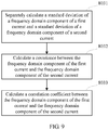
- the correlation coefficient between the frequency domain component of the first current and the frequency domain component of the second current may be calculated in the following manner: first, separately calculating a standard deviation of the frequency domain component of the first current and a standard deviation of the frequency domain component of the second current; then, calculating a covariance between the frequency domain component of the first current and the frequency domain component of the second current; and finally, calculating the correlation coefficient between the frequency domain component of the first current and the frequency domain component of the second current based on the standard deviations and the covariance.
- the correlation coefficient can reflect a degree of correlation between the frequency domain component of the first current and the frequency domain component of the second current. Whether the system is to send an alarm can be relatively accurately determined based on the degree of correlation.
- the first current meets the electric arc occurrence condition and the calculated correlation coefficient is greater than the preset coefficient threshold
- no direct current electric arc fault alarm is sent.
- a direct current electric arc fault alarm is sent. Therefore, a normal direct current electric arc fault alarm is sent after the condition-based determining succeeds. In this way, alarm performance of the system is not affected.
- the first current is a current obtained by performing sampling on a positive bus bar or a negative bus bar of the direct current cable
- the second current is a current obtained by performing sampling on all alternating current cables on the alternating current port side of the inverter.
- the first current is a direct current input current
- the second current is an alternating current common mode current.
- the first current is a direct current input current
- the second current is an alternating current common mode current
- electric arc analysis is performed on the first current before the correlation coefficient between the frequency domain component of the first current and the frequency domain component of the second current is calculated.
- the correlation coefficient is calculated only when the first current meets the electric arc occurrence condition, in other words, when it is determined, based only on the first current, that a direct current electric arc fault is likely to occur. Otherwise, the correlation coefficient does not need to be calculated.
- the first current is a direct current input current
- the second current is an alternating current common mode current
- the correlation coefficient is greater than or equal to the preset coefficient threshold, and the second current meets the electric arc occurrence condition, no direct current electric arc fault alarm is sent.
- the first current is a direct current input current
- the second current is an alternating current common mode current
- the correlation coefficient is greater than or equal to the preset coefficient threshold, and the second current does not meet the electric arc occurrence condition, a direct current electric arc fault alarm is sent.
- the first current is a current obtained by performing sampling on a positive bus bar or a negative bus bar of the direct current cable
- the second current is a current obtained by performing sampling on all direct current cables on the direct current port side of the inverter.
- the first current is a direct current input current
- the second current is a direct current common mode current.
- the first current is a direct current input current
- the second current is a direct current common mode current
- a second aspect of the embodiments of this application further provides an apparatus for detecting a direct current electric arc.
- the apparatus includes an electric arc fault processing module, and a first sampling module and a second sampling module that are connected to the processing unit.
- the first sampling module is configured to perform sampling to obtain a first current
- the second sampling module is configured to perform sampling to obtain a second current.
- the electric arc fault processing module receives the first current and the second current, and executes corresponding determining logic: first, calculating a frequency domain component of the first current and a frequency domain component of the second current; then, calculating a correlation coefficient between the two frequency domain components, where the frequency domain component is a frequency value of a current within a preset frequency band in frequency domain, and the correlation coefficient reflects a degree of correlation between the frequency domain component of the first current and the frequency domain component of the second current; and finally, performing condition-based determining, where when the electric arc fault processing module determines that the first current meets an electric arc occurrence condition and the correlation coefficient is greater than or equal to a preset coefficient threshold, the electric arc fault processing module does not send a direct current electric arc fault alarm.
- the first sampling module is a direct current cable current sampling module
- the first current is a direct current input current obtained by the direct current cable current sampling module by performing sampling on a positive bus bar or a negative bus bar of a direct current cable.
- the second sampling module is a common mode current sampling module, and when the common mode current sampling module is disposed on a direct current cable on a direct current port side of the inverter, the common mode current sampling module performs sampling on all direct current cables, to obtain a direct current common mode current, or when the common mode current sampling module is disposed on the alternating current cable on the alternating current port side of the inverter, the common mode current sampling module performs sampling on all alternating current cables, to obtain an alternating current common mode current.
- the direct current cable current sampling module has a plurality of implementations.
- the direct current cable current sampling module includes a first sampling coil and a first sampling control unit, the positive bus bar or the negative bus bar of the direct current cable runs through the first sampling coil, and the sampling control unit is configured to convert a current sampled by the first sampling coil into the direct current input current.
- the common mode current sampling module has a plurality of implementations.
- the common mode current sampling module includes a second sampling coil and a second sampling control unit, and when the common mode current sampling module performs sampling on the direct current cables, all the direct current cables run through the second sampling coil, or when the common mode current sampling module performs sampling on the alternating current cables, all the alternating current cables run through the second sampling coil.
- that the electric arc fault processing module determines that the first current meets an electric arc occurrence condition may be: first, performing frequency domain decomposition on the first current to obtain a first frequency range, where the first frequency range is a frequency band in which electric arc noise occurs; then, calculating a standard deviation of a current frequency value in the first frequency range; and obtaining a quantity N of times that the standard deviation is greater than a first threshold in a preset time period, and when N is greater than a second threshold, determining that the first current meets the electric arc occurrence condition, where N is an integer that is greater than or equal to 0. Whether the first current has a direct current electric arc can be relatively accurately determined by determining the quantity of times.
- the electric arc fault processing module obtains, through counting of a sliding window, the quantity N of times that the standard deviation is greater than the first threshold in the preset time period. A relatively accurate quantity N of times can be obtained in this manner.
- the electric arc fault processing module may calculate the correlation coefficient between the frequency domain component of the first current and the frequency domain component of the second current in the following manner: first, separately calculating a standard deviation of the frequency domain component of the first current and a standard deviation of the frequency domain component of the second current; then, calculating a covariance between the frequency domain component of the first current and the frequency domain component of the second current; and finally, calculating the correlation coefficient between the frequency domain component of the first current and the frequency domain component of the second current based on the standard deviations and the covariance.
- the correlation coefficient can reflect a degree of correlation between the frequency domain component of the first current and the frequency domain component of the second current. Whether the system is to send an alarm can be relatively accurately determined based on the degree of correlation.
- the electric arc fault processing module when the first current meets the electric arc occurrence condition and the calculated correlation coefficient is greater than the preset coefficient threshold, the electric arc fault processing module does not send a direct current electric arc fault alarm. Further, when determining that the first current meets the electric arc occurrence condition and the correlation coefficient is less than the preset coefficient threshold, the electric arc fault processing module sends a direct current electric arc fault alarm. Therefore, a normal direct current electric arc fault alarm is sent after the condition-based determining succeeds. In this way, alarm performance of the system is not affected.
- the electric arc fault processing module when the second current is an alternating current common mode current, the electric arc fault processing module further performs electric arc analysis on the first current, and then performs determining.
- the correlation coefficient is calculated only when the first current meets the electric arc occurrence condition, in other words, when it is determined, based only on the first current, that a direct current electric arc fault is likely to occur. Otherwise, the correlation coefficient does not need to be calculated.
- the electric arc fault processing module when determining that the first current meets the electric arc occurrence condition, the correlation coefficient is greater than or equal to the preset coefficient threshold, and the second current meets the electric arc occurrence condition, the electric arc fault processing module does not send a direct current electric arc fault alarm.
- the electric arc fault processing module is further configured to: when determining that the first current meets the electric arc occurrence condition, the correlation coefficient is greater than or equal to the preset coefficient threshold, and the second current does not meet the electric arc occurrence condition, send a direct current electric arc fault alarm.
- the electric arc fault processing module when the second current is a direct current common mode current, after calculating the correlation coefficient between the frequency domain component of the first current and the frequency domain component of the second current, if the electric arc fault processing module finds that the correlation coefficient is less than the preset coefficient threshold, the electric arc fault processing module performs electric arc analysis on the first current.
- Embodiments of this application provide a method for processing a direct current electric arc and an apparatus, to resolve a problem that a false alarm caused by relatively large common mode current noise in a photovoltaic system affects normal operation of the photovoltaic system.
- a process, method, system, product, or device that includes a series of steps or units is not necessarily limited to those steps or units that are expressly listed, but may include other steps or units that are not expressly listed or inherent to such a process, method, system, product, or device.
- the NEC Corporation formulated a regulation that a faulty electric arc detection apparatus and a breaker need to be added to a photovoltaic system, and formulated an industry standard of the photovoltaic system, to ensure stable, safe, and reliable operation of the photovoltaic system.
- causes of a direct current electric arc of the photovoltaic system are of great randomness, and both an occurrence location and occurrence time of the direct current electric arc are unpredictable.
- An electric arc fault may be caused by severe cable and line weathering, direct current line breakage, electronic component aging, connecting contact point looseness, animal gnawing, or the like. A relatively large quantity of incidental factors make it impossible to accurately establish a mathematical model to directly determine whether a direct current electric arc fault occurs in the photovoltaic system.
- a direct current electric arc fault detection method is that based on an indirect relationship between the current noise and the direct current electric arc fault, whether a direct current electric arc fault occurs is determined based on a magnitude of the current noise in the direct current cable.
- a method for obtaining the current noise in the direct current cable is: first sampling a current of the direct current cable, and then performing FFT or wavelet transform on a sampling result, to obtain a corresponding noise frequency current component.
- FIG. 1 is a schematic diagram of a photovoltaic power generation system. If common mode current noise is relatively large, an electric arc detection system is affected when no direct current electric arc fault actually occurs, and consequently a false alarm is generated, affecting normal operation of the photovoltaic system. Therefore, during direct current electric arc detection of the photovoltaic system, how to suppress common mode current interference to improve detection system accuracy is a very crucial issue.
- FIG. 2a is a schematic diagram of detecting a direct current electric arc
- FIG. 2b is another schematic diagram of detecting a direct current electric arc.
- a direct current cable current sampling unit mainly samples a direct current cable current
- an electric arc fault determining unit determines, based on the direct current cable current, whether an electric arc fault occurs.
- a differential calculation unit is added to process sampled currents, and then whether an electric arc fault occurs is determined based on a differential calculation result of the direct current cable current.
- FIG. 3 is a schematic structural diagram of a differential suppression method of adjacent photovoltaic branches.
- direct current cable currents of the adjacent photovoltaic cell panel branches are sampled; then, the sampled currents of the adjacent branches are sent to a differential unit to perform differential calculation, to cancel a common mode current component in the measured currents; and finally, a calculated direct current cable current that does not include the common mode current component is sent to an electric arc fault determining unit to perform noise detection, to determine whether a direct current electric arc fault occurs in a system.
- this manner has two relatively obvious disadvantages.
- One disadvantage is that this manner is applicable only to a photovoltaic power generation system having a plurality of photovoltaic inputs, namely, a centralized photovoltaic power generation system. If a photovoltaic system has only one string, there is no adjacent photovoltaic cell panel branches, and therefore a plurality of detection currents cannot be obtained to perform differential calculation. For example, this manner cannot be applied to a string photovoltaic power generation system and a household small-size photovoltaic power generation system, and therefore application scenarios of this manner are very limited.
- the other disadvantage is that real-time differential calculation on currents of adjacent branches is implemented with great difficulty and very low accuracy in actual application.
- FIG. 4 is a schematic structural diagram of a differential suppression method of a positive direct current bus bar and a negative direct current bus bar
- FIG. 5 is a schematic diagram of a three-winding or three-column transformer.
- a positive bus bar current and a negative bus bar current of photovoltaic cell panel direct current bus bars are sampled; then, the sampled currents of adjacent branches are sent to a differential unit to perform differential calculation, to cancel a common mode current component in the measured currents; and finally, a calculated direct current cable current that does not include the common mode current component is sent to an electric arc fault determining unit to perform noise detection, to determine whether a direct current electric arc fault occurs in a system.
- the differential unit has different implementations: using the differential calculation unit to perform cancellation in a sampling portion, or using the three-winding or three-column transformer shown in FIG. 5 to directly perform magnetic circuit cancellation.
- This method is relatively applicable to a normal power supply system.
- a photovoltaic cell system is installed in a plurality of manners, for example, the positive bus bar is grounded, the negative bus bar is grounded, and neither the positive bus bar nor the negative bus bar is grounded.
- the direct current positive bus bar and negative bus bar in a common mode current loop are inconsistent in equivalent common mode impedance, and therefore are also inconsistent in common mode current.
- Problems in actual application are similar to those of the prior art 1, to be specific, an operating status of the photovoltaic power generation system is greatly affected by external factors and changes in real time. Therefore, it is difficult to balance gains during differential calculation, causing relatively low calculation accuracy.
- this application provides a method for detecting a direct current electric arc.
- This method is based on a correlation theory in statistics, and different variables used to calculate correlation can be sampled synchronously. Therefore, this method is insensitive to a change of an actual working condition of the photovoltaic system, and therefore has higher accuracy than the existing accurate numerical calculation method.
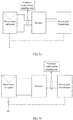
- FIG. 6 is a schematic architectural diagram of a method for processing a direct current electric arc fault according to this embodiment of this application.
- two sampling units namely, a direct current cable current sampling unit and a common mode current sampling unit
- the direct current cable current sampling unit mainly samples a direct current cable current
- the common mode current sampling unit mainly samples data of a common mode current.
- the common mode current sampling unit may be connected to a direct current port side of an inverter to sample a direct current common mode current, or may be connected to an alternating current port side of the inverter to sample an alternating current common mode current.
- FIG. 7a and FIG. 7b For details, refer to FIG. 7a and FIG. 7b.
- FIG. 7a is a schematic diagram in which the common mode current sampling unit is connected to the direct current port side in the architecture according to this embodiment of this application; and FIG. 7b is a schematic diagram in which the common mode current sampling unit is connected to the alternating current port side in the architecture according to this embodiment of this application.
- an electric arc fault processing unit is used to calculate correlation between the direct current cable current and the common mode current.
- the common mode current sampling unit cannot accurately obtain a specific numerical value of an actual common mode current.
- a change trend of a common mode current sampling value is obtained to alleviate the impact.
- the total noise is relatively large, and therefore a direct current electric arc fault determining condition is usually triggered, and a direct current electric arc alarm is generated.
- the differential mode noise is actually relatively small, and the system is actually in normal operation. Therefore, a false alarm is very likely to generate.
- the common mode noise is relatively large, the differential mode noise is also relatively large. Although the common mode noise may cause some interference, a direct current electric arc fault is certainly likely to occur in the circuit in this case, and therefore a false alarm probability is also relatively low.
- the false alarm probability is relatively high only in the case 2. Although interference exists in the other three cases, the false alarm probability is actually relatively low. Therefore, the high-probability false alarm problem in the case 2 needs to be resolved as a key point.
- a main noise component in the direct current cable current is the common mode noise, and the common mode noise is correlated with the common mode current in the photovoltaic power generation system in this case to some extent, and has a relatively similar change trend to the common mode current.
- a one-to-one correspondence cannot be obtained through accurate calculation, a linear correlation between the direct current cable current and the common mode current can be calculated by using a statistics method.
- the direct current cable current is highly correlated with the common mode current in the photovoltaic system, and therefore a correlation coefficient between the two types of currents is set to a determining condition in this embodiment of this application, to reduce the false alarm probability of the system.
- the following describes a method for processing a direct current electric arc according to an embodiment of this application.
- FIG. 8 is a diagram of an embodiment of a method for processing a direct current electric arc according to an embodiment of this application.
- the method may include the following steps.
- the first current is a current obtained from a direct current cable connected to a photovoltaic cell panel.
- the first current is a direct current input current
- the direct current cable is used by the photovoltaic cell panel to output a direct current to an inverter
- the direct current input current is the direct current output by the photovoltaic cell panel to the inverter.
- the second current is a current obtained from a direct current cable on a direct current port side of the inverter or a current obtained from an alternating current cable on an alternating current port side of the inverter.
- the second current is a common mode current, and the alternating current cable is used by the inverter to output an alternating current. It can be understood that the second current is obtained in two manners. As shown in FIG. 7a and FIG. 7b , the second current is obtained from the direct current port side of the inverter in FIG. 7a , and the second current is obtained from the alternating current port side of the inverter in FIG. 7b .
- the second current obtained from the direct current port side is a direct current, and the second current obtained from the alternating current port is an alternating current.
- first current in step 801 and the second current in step 802 are sampled in a continuous process, sampling may be performed once at an interval of a cycle, and different cycles may be of same duration or of different duration.
- the sampling may last for a preset time period, the preset time period includes at least one cycle, and data used to subsequently calculate a correlation coefficient is all data collected in the preset time period.
- step 801 and step 802 the current may be sampled from the direct current cable or the alternating current cable in a plurality of manners, but all the manners should follow a process of sampling, conditioning, and control.
- sampling processes There are a plurality of types of sampling processes, for example:
- Type 1 Sampling is performed by using a current transformer.
- a cable from which a current is to be sampled is placed in a disposed coil, and according to the Electromagnetic Induction Law, the cable through which the detected current flows winds around the coil.
- the cable is used as a primary winding, and the measurement coil is used as a secondary winding.
- the cable generates an electromagnetic field after being electrified, and therefore an induced current is generated in the coil.
- a current in the cable may be obtained in an intermediate conditioning step in which some mathematical operations are performed on the induced current. For example, a preset correspondence between the induced current and an actual current is obtained through experiments, and then the current in the cable can be obtained based on the induced current during actual sampling.
- the common mode current sampling units in FIG. 7a and FIG. 7b use this manner.
- Type 2 Sampling is performed in a small-resistance non-conductive manner.
- a small-resistance resistor is connected to a current return circuit in series, a voltage difference between two ends of the small-resistance resistor is measured, and according to the Ohm's law, a voltage is divided by a resistance to obtain a detected current.
- power needs to be large enough, and an inductance of the resistor needs to be small, to eliminate a voltage drop caused by inductive reactance on the two ends of the resistor.
- Type 3 Sampling is performed by using a Hall current sensor. In this manner, sampling is mainly performed based on the Hall effect.
- a current is perpendicular to an external magnetic field and flows through a conductor, a current carrier deflects, and an additional electric field may be generated in a direction perpendicular to the current and the magnetic field, and therefore an electric potential difference is generated between two ends of the conductor. This is the Hall effect, and the electric potential difference is also referred to as the Hall electric potential difference.
- the conditioning step needs to be added between the sampling step and the control step to compensate for and correct a measured result. This is because high-frequency noise usually occurs in a mathematical signal that is obtained in the sampling step and that is related to a detected current signal, and an amplitude of the mathematical signal is larger or smaller than a signal required in the control step.
- a filter, an operational amplifier, and the like are commonly used in the conditioning step.
- control step is a step in which the method for processing a direct current electric arc according to this embodiment of this application is performed. Control can be performed only after a conditioned current value is obtained.
- the frequency domain component is a frequency value of a current within a preset frequency band in frequency domain. Because a direct current electric arc pre-alarm is mainly researched in this application, the frequency domain component in this embodiment of this application is in a frequency band in which a high-frequency current exists when an electric arc occurs, for example, between 30 kHz and 80 kHz. In addition, regardless of a direct current or an alternating current, any current that can generate an electric arc can generate a frequency domain component, and any current corresponding to the electric arc is presented in a high-frequency and unstable manner. For the direct current, a changing amplitude of the direct current is simulated to a high-frequency component in a manner such as Fourier expansion.
- the alternating current is represented as an alternating current with a non-sinusoidal cycle.
- the correlation coefficient is a statistical indicator designed by a famous statistician Karl Pearson. Compared with a correlation table and a correlation diagram that can reflect only a correlation and a correlation direction between two variables but cannot exactly show a degree of correlation between the two variables, the correlation coefficient is a statistical indicator used to reflect a degree of correlation between variables.
- the correlation coefficient is calculated by using a product-moment method. Based on dispersions between two variables and respective average values, the two dispersions are multiplied to reflect a degree of correlation between the two variables. A linear single-correlation coefficient is researched as a key point.
- a correlation is a nondeterministic relationship
- a correlation coefficient is a quantity used to research a degree of linear correlation between variables. Due to different research objects, the correlation coefficient may be defined in the following several manners:
- the correlation coefficient in this embodiment of this application is mainly implemented in the last two manners.
- FIG. 9 is a schematic diagram of a correlation coefficient calculation method in the method for processing a direct current electric arc according to this embodiment of this application.
- Step 803 may include the following sub-steps:
- a standard deviation of a frequency domain component of one of the collected first currents is calculated.
- the correlation coefficient r xy is actually a ratio of the covariance s xy to a product of the standard deviation s x of the first current x and the standard deviation s y of the second current y.
- the ratio can reflect a proportion of common mode noise generated by the second current in total noise. Therefore, the ratio can be used as a basis to determine whether a current case is the case 2 in Table 1.
- the total noise is obtained by adding up the common mode noise generated by the second current and differential mode noise of a photovoltaic system.
- step 805 Determine whether the first current meets an electric arc occurrence condition and whether the correlation coefficient is less than a preset coefficient threshold, and perform step 805 when the first current meets the electric arc occurrence condition and the correlation coefficient is greater than or equal to the preset coefficient threshold.
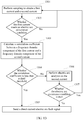
- FIG. 10 is a schematic diagram of a method for determining whether a current meets an electric arc occurrence condition in the method for processing a direct current electric arc according to this embodiment of this application.
- the first current is used as an example.
- frequency domain decomposition is performed on the first current, and a specific frequency band is selected in a filtering manner, for example, a range from 30 kHz to 80 kHz is selected. This range is selected mainly because this range is a frequency band in which main electric arc current noise occurs.
- the standard deviation of the first current is calculated, and then the standard deviation is compared with a standard deviation threshold (namely, a first threshold). If the standard deviation is greater than the standard deviation threshold, a count is increased by 1, and one standard deviation calculation process is completed. A quantity N of times that the standard deviation of the selected first current is greater than the standard deviation threshold in a period of time is counted. Finally, determining is performed on the calculated N and a second threshold, and when N is greater than the second threshold, it indicates that the first current meets the electric arc occurrence condition, or when N is not greater than the second threshold, it indicates that the first current does not meet the electric arc occurrence condition.
- a standard deviation threshold namely, a first threshold
- FIG. 11 is a schematic flowchart of a sliding window in the method for processing a direct current electric arc according to this embodiment of this application.
- a specific implementation of this sliding window technology includes two phases: an initialization phase and a logical comparison and calculation phase. In the initialization phase, all arrays N 1 are set to 0. Then, in the logical comparison and calculation phase, n is set to 0.
- a sum of the arrays N 1 is calculated and a result is output to obtain N.
- N may be compared with the second threshold, and if N is greater than the second threshold, it indicates that the current meets the electric arc occurrence condition, or if N is not greater than the second threshold, it indicates that the current does not meet the electric arc occurrence condition.
- This process is one electric arc occurrence condition determining process in one time period. After this process is completed, n is increased by 1, and an electric arc occurrence condition determining process in a next time period starts.
- the calculated correlation coefficient between the frequency domain component of the first current and the frequency domain component of the second current is used to reflect a proportion of common mode noise generated by the second current, and the preset coefficient threshold is set. If the correlation coefficient is greater than the coefficient threshold, it indicates that the first current meets the electric arc occurrence condition because the common mode noise is relatively large. In this case, no alarm needs to be sent. Therefore, in this embodiment of this application, a direct current electric arc fault alarm is not sent when it is found that the first current meets the electric arc occurrence condition and the correlation coefficient is greater than or equal to the preset threshold.
- the method may further include the following step: 806. Send a direct current electric arc fault alarm.
- step 804 may further include the following sub-step.
- step 806 is performed.
- step 805 is performed regardless of whether the correlation coefficient is less than the preset coefficient threshold.
- FIG. 12 is a schematic architectural diagram of a system for processing a direct current electric arc according to an embodiment of this application
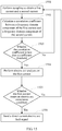
- FIG. 13 is a diagram of an embodiment of a method for processing a direct current electric arc according to this embodiment of this application.
- a current transform manner is used in FIG. 12 and FIG. 13 .
- FIG. 12 all alternating current cables run through a second coil of a common mode current sampling unit, and a positive bus bar or a negative bus bar runs through a first coil of a direct current sampling unit.
- the method includes the following steps.
- step 801 and step 802 for the sampling process, refer to step 801 and step 802 in the embodiment shown in FIG. 8 . Details are not described herein again.
- step 1302. Determine whether the first current meets an electric arc occurrence condition, and perform step 1303 if the first current meets the electric arc occurrence condition, or perform step 1301 if the first current does not meet the electric arc occurrence condition.
- step 804 For whether the first current meets the electric arc occurrence condition, refer to the description of step 804 in the embodiment shown in FIG. 8 . Details are not described herein again.
- step 803 For the correlation coefficient between the frequency domain component of the first current and the frequency domain component of the second current, refer to the description of step 803 in the embodiment shown in FIG. 8 . Details are not described herein again.
- step 1304. Determine whether the correlation coefficient is less than a preset coefficient threshold, and perform step 1305 if the correlation coefficient is less than the preset coefficient threshold, or perform step 1306 if the correlation coefficient is not less than the preset coefficient threshold.
- step 803 For the correlation coefficient, refer to the description of step 803 in the embodiment shown in FIG. 8 . Details are not described herein again.
- step 804 For the electric arc analysis process, refer to the description of step 804 in the embodiment shown in FIG. 8 . Details are not described herein again.
- step 1305 is performed to send a direct current electric arc fault alarm.
- FIG. 14 is a schematic architectural diagram of a system for processing a direct current electric arc according to an embodiment of this application
- FIG. 15 is a diagram of an embodiment of a method for processing a direct current electric arc according to this embodiment of this application.
- a positive bus bar or a negative bus bar runs through a first coil of a direct current sampling unit
- a positive bus bar or a negative bus bar runs through a second coil of a common mode current sampling unit.
- the method includes the following steps.
- step 801 and step 802 for the sampling process, refer to step 801 and step 802 in the embodiment shown in FIG. 8 . Details are not described herein again.
- step 803 For the correlation coefficient between the frequency domain component of the first current and the frequency domain component of the second current, refer to the description of step 803 in the embodiment shown in FIG. 8 . Details are not described herein again.
- step 1503. Determine whether the correlation coefficient is less than a preset coefficient threshold, and perform step 1504 if the correlation coefficient is less than the preset coefficient threshold, or perform step 1501 if the correlation coefficient is not less than the preset coefficient threshold.
- step 803 For the correlation coefficient, refer to the description of step 803 in the embodiment shown in FIG. 8 . Details are not described herein again.
- step 804 For the electric arc analysis process, refer to the description of step 804 in the embodiment shown in FIG. 8 . Details are not described herein again.
- step 1505. Determine whether the first current meets an electric arc occurrence condition, and perform step 1506 if the first current meets the electric arc occurrence condition, or perform step 1501 if the first current does not meet the electric arc occurrence condition.
- step 804 For the electric arc analysis process, refer to the description of step 804 in the embodiment shown in FIG. 8 . Details are not described herein again.
- This application is based on a statistics method.
- the correlation coefficient between the direct current cable current and the common mode current is used as a basis for determining. This can avoid an error caused by different working conditions to an accurate numerical value-based calculation method, and can suppress a false alarm caused by the common mode current on a direct current electric arc fault of the photovoltaic inverter, thereby improving accuracy of direct current electric arc fault detection, reducing interference on normal operation of the inverter, and improving product performance.
- the direct current cable current and the common mode current that are used to calculate the correlation coefficient can be sampled synchronously, and are both sampling results under a same working condition. Therefore, impact of a working condition change of a photovoltaic power generation system on a detection result can be alleviated.
- the embodiments of this application are applicable to a three-phase inverter product, a single-phase inverter product, a string inverter product, and a centralized inverter product, and therefore have a wide coverage area.
- All or some of the foregoing embodiments may be implemented by using software, hardware, firmware, or any combination thereof.
- the embodiments may be implemented completely or partially in a form of a computer program product.
- the disclosed system, apparatus, and method may be implemented in other manners.
- the described apparatus embodiment is merely an example.
- the unit division is merely logical function division and may be other division in actual implementation.
- a plurality of units or components may be combined or integrated into another system, or some features may be ignored or not performed.
- the displayed or discussed mutual couplings or direct couplings or communication connections may be implemented by using some interfaces.
- the indirect couplings or communication connections between the apparatuses or units may be implemented in electrical, mechanical, or other forms.
- the units described as separate parts may or may not be physically separate, and parts displayed as units may or may not be physical units, to be specific, may be located in one place, or may be distributed on a plurality of network units. Some or all of the units may be selected based on actual requirements to achieve the objectives of the solutions of the embodiments.
- functional units in the embodiments of this application may be integrated into one processing unit, or each of the units may exist alone physically, or two or more units are integrated into one unit.
- the integrated unit may be implemented in a form of hardware, or may be implemented in a form of a software functional unit.
Landscapes
- Engineering & Computer Science (AREA)
- Power Engineering (AREA)
- Physics & Mathematics (AREA)
- General Physics & Mathematics (AREA)
- Artificial Intelligence (AREA)
- Evolutionary Computation (AREA)
- Testing Of Short-Circuits, Discontinuities, Leakage, Or Incorrect Line Connections (AREA)
- Photovoltaic Devices (AREA)
Applications Claiming Priority (1)
| Application Number | Priority Date | Filing Date | Title |
|---|---|---|---|
| PCT/CN2017/120040 WO2019127440A1 (zh) | 2017-12-29 | 2017-12-29 | 一种直流电弧的处理方法及装置 |
Publications (3)
| Publication Number | Publication Date |
|---|---|
| EP3723218A1 true EP3723218A1 (de) | 2020-10-14 |
| EP3723218A4 EP3723218A4 (de) | 2020-12-16 |
| EP3723218B1 EP3723218B1 (de) | 2021-12-29 |
Family
ID=67062885
Family Applications (1)
| Application Number | Title | Priority Date | Filing Date |
|---|---|---|---|
| EP17936310.6A Active EP3723218B1 (de) | 2017-12-29 | 2017-12-29 | Verfahren und vorrichtung zur handhabung eines gleichstromlichtbogens |
Country Status (6)
| Country | Link |
|---|---|
| US (1) | US11693062B2 (de) |
| EP (1) | EP3723218B1 (de) |
| CN (1) | CN111512511B (de) |
| DK (1) | DK3723218T3 (de) |
| ES (1) | ES2905541T3 (de) |
| WO (1) | WO2019127440A1 (de) |
Families Citing this family (13)
| Publication number | Priority date | Publication date | Assignee | Title |
|---|---|---|---|---|
| CN110908844B (zh) * | 2019-10-24 | 2022-03-08 | 珠海格力电器股份有限公司 | 电弧故障检测方法、装置、计算机可读存储介质及插座 |
| CN112305308B (zh) * | 2020-10-21 | 2023-08-11 | 阳光电源股份有限公司 | 一种直流电弧检测方法、装置及组串逆变器 |
| CN114966205B (zh) * | 2021-02-19 | 2024-07-30 | 华为数字能源技术有限公司 | 一种绝缘阻抗检测方法、装置及系统 |
| CN113189455B (zh) * | 2021-04-02 | 2022-05-17 | 广东工业大学 | 一种基于局部放电量差异的动车组高压电缆缺陷程度评估方法 |
| CN113687258B (zh) * | 2021-09-10 | 2025-01-10 | 阳光电源股份有限公司 | 一种直流电源供电系统及其直流电弧检测方法和装置 |
| CN113884884B (zh) * | 2021-10-21 | 2022-07-26 | 山东大学 | 一种基于相关性的动力电池组故障诊断方法及系统 |
| CN114280440B (zh) * | 2022-03-04 | 2022-06-28 | 固德威技术股份有限公司 | 一种光伏直流电弧故障识别装置、识别方法及光伏系统 |
| CN114790549B (zh) * | 2022-04-14 | 2024-02-02 | 青岛雅合科技发展有限公司 | 周期性动态直流干扰分析方法 |
| CN115149900B (zh) * | 2022-06-27 | 2024-11-22 | 华为数字能源技术有限公司 | 光伏变换器以及光伏发电系统 |
| CN116106700B (zh) * | 2023-01-31 | 2025-09-05 | 国网湖南省电力有限公司 | 一种故障电弧检测方法及装置 |
| CN116068346B (zh) * | 2023-02-16 | 2024-12-03 | 固德威技术股份有限公司 | 一种电弧故障确认方法、装置以及介质 |
| CN117895595A (zh) * | 2023-12-06 | 2024-04-16 | 华为数字能源技术有限公司 | 一种具有共模拉弧检测功能的储能系统及光储设备 |
| CN119199348B (zh) * | 2024-10-28 | 2025-03-21 | 上海思格新能源技术有限公司 | 逆变器系统的检测方法、装置和逆变器系统 |
Family Cites Families (10)
| Publication number | Priority date | Publication date | Assignee | Title |
|---|---|---|---|---|
| US8659856B2 (en) * | 2005-12-09 | 2014-02-25 | Hamilton Sundstrand Corporation | DC arc fault detection and protection |
| JP5369490B2 (ja) * | 2008-05-13 | 2013-12-18 | シンフォニアテクノロジー株式会社 | アーク検出装置及びこれを備えた航空機 |
| CN102253293A (zh) * | 2011-05-30 | 2011-11-23 | 南京航空航天大学 | 一种直流电弧故障检测方法及装置 |
| US8599523B1 (en) * | 2011-07-29 | 2013-12-03 | Leviton Manufacturing Company, Inc. | Arc fault circuit interrupter |
| DE102012218504A1 (de) * | 2012-10-11 | 2014-04-17 | Bender Gmbh & Co. Kg | Differenzstrom-Überwachungseinrichtung mit Lichtbogenerkennung |
| EP2887082B1 (de) * | 2013-12-23 | 2019-09-18 | Sensata Technologies, Inc. | Verbesserte Rauschübertragungsimmunität einer mehrstrangigen Lichtbogenfehlerdetektionsvorrichtung |
| CN103913663B (zh) * | 2014-04-21 | 2017-01-25 | 南京航空航天大学 | 一种直流系统电弧故障在线检测方法和保护装置 |
| CN104597344A (zh) | 2015-01-08 | 2015-05-06 | 上海交通大学 | 基于小波一层高频分量相关性的故障电弧在线检测方法 |
| CN104811135B (zh) | 2015-04-16 | 2017-04-26 | 西安交通大学 | 一种共模信号干扰条件下的光伏系统故障电弧检测方法 |
| CN106771691A (zh) * | 2015-11-20 | 2017-05-31 | 台达电子工业股份有限公司 | 改良型电弧侦测装置 |
-
2017
- 2017-12-29 WO PCT/CN2017/120040 patent/WO2019127440A1/zh not_active Ceased
- 2017-12-29 EP EP17936310.6A patent/EP3723218B1/de active Active
- 2017-12-29 CN CN201780098086.8A patent/CN111512511B/zh active Active
- 2017-12-29 ES ES17936310T patent/ES2905541T3/es active Active
- 2017-12-29 DK DK17936310.6T patent/DK3723218T3/da active
-
2020
- 2020-06-26 US US16/913,828 patent/US11693062B2/en active Active
Also Published As
| Publication number | Publication date |
|---|---|
| WO2019127440A1 (zh) | 2019-07-04 |
| US11693062B2 (en) | 2023-07-04 |
| CN111512511A (zh) | 2020-08-07 |
| DK3723218T3 (da) | 2022-01-31 |
| EP3723218B1 (de) | 2021-12-29 |
| CN111512511B (zh) | 2021-08-20 |
| EP3723218A4 (de) | 2020-12-16 |
| ES2905541T3 (es) | 2022-04-11 |
| US20200326385A1 (en) | 2020-10-15 |
Similar Documents
| Publication | Publication Date | Title |
|---|---|---|
| US11693062B2 (en) | Method for processing direct current electric arc and apparatus | |
| KR101574615B1 (ko) | 통계적 위상패턴 기반의 신호검출 방법을 이용한 전력설비 부분 방전 감시진단 시스템 | |
| US20210036656A1 (en) | Arc fault detection method for photovoltaic system based on adaptive kernel function and instantaneous frequency estimation | |
| WO2023045008A1 (zh) | 基于小波分解的智能自适应电弧检测方法及其应用装置 | |
| CN113985235B (zh) | 分布式电弧检测系统、具有其的光伏系统及电弧检测方法 | |
| WO2024027455A1 (zh) | 一种电弧光谱识别方法和装置 | |
| EP4005047B1 (de) | Anomaliedetektion in energiesystemen | |
| CN119575078A (zh) | 一种水电站馈线故障检测系统及方法 | |
| Khalili et al. | Traveling wave‐based protection for TCSC connected transmission lines using game theory | |
| Chen et al. | Location for single‐phase grounding fault in distribution network based on equivalent admittance distortion rate | |
| CN104198893B (zh) | 自适应故障电流检测方法 | |
| Shukla et al. | Enhancing the reliability of six‐phase transmission line protection using power quality informatics with real‐time validation | |
| Petite et al. | A comprehensive backup protection for transmission lines based on an intelligent wide‐area monitoring system | |
| Sabra et al. | Enhancing Fault Detection and Localization in MT-MVDC Networks Using Advanced Singular Spectrum Analysis | |
| Yong et al. | High impedance fault identification method of the distribution network based on discrete wavelet transformation | |
| Kale et al. | Faulted phase selection on double circuit transmission line using wavelet transform and neural network | |
| Li et al. | Adaptive differential protection method for active distribution network based on DTW distance algorithm | |
| CN117977507A (zh) | 一种基于时域特征的有源配电网纵联保护方法及系统 | |
| CN118150942A (zh) | 一种配电网电流接地故障定位方法、装置、设备及介质 | |
| Wang et al. | A Fast Fault Location Method for Distribution Network Based on Line Topology and Beat Frequency Attenuation Discrimination | |
| CN117630590A (zh) | Gis设备局放监测宽频电流传感阵列系统的构造方法 | |
| CN110244144B (zh) | 一种避雷器状态监测方法及交流数据采集方法 | |
| CN117289087A (zh) | 一种基于czt变换的串联故障电弧检测方法 | |
| Chuirui et al. | Research on single-phase grounding fault line selection based on EMD method | |
| Jiang et al. | DC Series Arc Fault Detection and Localization Based on Photovoltaic Module‐Level Power Optimizer |
Legal Events
| Date | Code | Title | Description |
|---|---|---|---|
| STAA | Information on the status of an ep patent application or granted ep patent |
Free format text: STATUS: THE INTERNATIONAL PUBLICATION HAS BEEN MADE |
|
| PUAI | Public reference made under article 153(3) epc to a published international application that has entered the european phase |
Free format text: ORIGINAL CODE: 0009012 |
|
| STAA | Information on the status of an ep patent application or granted ep patent |
Free format text: STATUS: REQUEST FOR EXAMINATION WAS MADE |
|
| 17P | Request for examination filed |
Effective date: 20200706 |
|
| AK | Designated contracting states |
Kind code of ref document: A1 Designated state(s): AL AT BE BG CH CY CZ DE DK EE ES FI FR GB GR HR HU IE IS IT LI LT LU LV MC MK MT NL NO PL PT RO RS SE SI SK SM TR |
|
| AX | Request for extension of the european patent |
Extension state: BA ME |
|
| REG | Reference to a national code |
Ref country code: DE Ref legal event code: R079 Ref document number: 602017051748 Country of ref document: DE Free format text: PREVIOUS MAIN CLASS: H02H0003000000 Ipc: H02H0001000000 |
|
| A4 | Supplementary search report drawn up and despatched |
Effective date: 20201113 |
|
| RIC1 | Information provided on ipc code assigned before grant |
Ipc: H02H 1/00 20060101AFI20201109BHEP Ipc: H02H 3/33 20060101ALI20201109BHEP Ipc: H02S 50/00 20140101ALI20201109BHEP Ipc: G01R 31/00 20060101ALI20201109BHEP |
|
| DAV | Request for validation of the european patent (deleted) | ||
| DAX | Request for extension of the european patent (deleted) | ||
| GRAP | Despatch of communication of intention to grant a patent |
Free format text: ORIGINAL CODE: EPIDOSNIGR1 |
|
| STAA | Information on the status of an ep patent application or granted ep patent |
Free format text: STATUS: GRANT OF PATENT IS INTENDED |
|
| INTG | Intention to grant announced |
Effective date: 20210812 |
|
| GRAS | Grant fee paid |
Free format text: ORIGINAL CODE: EPIDOSNIGR3 |
|
| GRAA | (expected) grant |
Free format text: ORIGINAL CODE: 0009210 |
|
| STAA | Information on the status of an ep patent application or granted ep patent |
Free format text: STATUS: THE PATENT HAS BEEN GRANTED |
|
| AK | Designated contracting states |
Kind code of ref document: B1 Designated state(s): AL AT BE BG CH CY CZ DE DK EE ES FI FR GB GR HR HU IE IS IT LI LT LU LV MC MK MT NL NO PL PT RO RS SE SI SK SM TR |
|
| REG | Reference to a national code |
Ref country code: GB Ref legal event code: FG4D |
|
| REG | Reference to a national code |
Ref country code: CH Ref legal event code: EP |
|
| REG | Reference to a national code |
Ref country code: AT Ref legal event code: REF Ref document number: 1459393 Country of ref document: AT Kind code of ref document: T Effective date: 20220115 |
|
| REG | Reference to a national code |
Ref country code: IE Ref legal event code: FG4D |
|
| REG | Reference to a national code |
Ref country code: DE Ref legal event code: R096 Ref document number: 602017051748 Country of ref document: DE |
|
| REG | Reference to a national code |
Ref country code: DK Ref legal event code: T3 Effective date: 20220127 |
|
| REG | Reference to a national code |
Ref country code: LT Ref legal event code: MG9D Ref country code: ES Ref legal event code: FG2A Ref document number: 2905541 Country of ref document: ES Kind code of ref document: T3 Effective date: 20220411 |
|
| PG25 | Lapsed in a contracting state [announced via postgrant information from national office to epo] |
Ref country code: RS Free format text: LAPSE BECAUSE OF FAILURE TO SUBMIT A TRANSLATION OF THE DESCRIPTION OR TO PAY THE FEE WITHIN THE PRESCRIBED TIME-LIMIT Effective date: 20211229 Ref country code: LT Free format text: LAPSE BECAUSE OF FAILURE TO SUBMIT A TRANSLATION OF THE DESCRIPTION OR TO PAY THE FEE WITHIN THE PRESCRIBED TIME-LIMIT Effective date: 20211229 Ref country code: FI Free format text: LAPSE BECAUSE OF FAILURE TO SUBMIT A TRANSLATION OF THE DESCRIPTION OR TO PAY THE FEE WITHIN THE PRESCRIBED TIME-LIMIT Effective date: 20211229 Ref country code: BG Free format text: LAPSE BECAUSE OF FAILURE TO SUBMIT A TRANSLATION OF THE DESCRIPTION OR TO PAY THE FEE WITHIN THE PRESCRIBED TIME-LIMIT Effective date: 20220329 |
|
| REG | Reference to a national code |
Ref country code: NL Ref legal event code: MP Effective date: 20211229 |
|
| REG | Reference to a national code |
Ref country code: AT Ref legal event code: MK05 Ref document number: 1459393 Country of ref document: AT Kind code of ref document: T Effective date: 20211229 |
|
| PG25 | Lapsed in a contracting state [announced via postgrant information from national office to epo] |
Ref country code: SE Free format text: LAPSE BECAUSE OF FAILURE TO SUBMIT A TRANSLATION OF THE DESCRIPTION OR TO PAY THE FEE WITHIN THE PRESCRIBED TIME-LIMIT Effective date: 20211229 Ref country code: NO Free format text: LAPSE BECAUSE OF FAILURE TO SUBMIT A TRANSLATION OF THE DESCRIPTION OR TO PAY THE FEE WITHIN THE PRESCRIBED TIME-LIMIT Effective date: 20220329 Ref country code: LV Free format text: LAPSE BECAUSE OF FAILURE TO SUBMIT A TRANSLATION OF THE DESCRIPTION OR TO PAY THE FEE WITHIN THE PRESCRIBED TIME-LIMIT Effective date: 20211229 Ref country code: HR Free format text: LAPSE BECAUSE OF FAILURE TO SUBMIT A TRANSLATION OF THE DESCRIPTION OR TO PAY THE FEE WITHIN THE PRESCRIBED TIME-LIMIT Effective date: 20211229 Ref country code: GR Free format text: LAPSE BECAUSE OF FAILURE TO SUBMIT A TRANSLATION OF THE DESCRIPTION OR TO PAY THE FEE WITHIN THE PRESCRIBED TIME-LIMIT Effective date: 20220330 |
|
| PG25 | Lapsed in a contracting state [announced via postgrant information from national office to epo] |
Ref country code: NL Free format text: LAPSE BECAUSE OF FAILURE TO SUBMIT A TRANSLATION OF THE DESCRIPTION OR TO PAY THE FEE WITHIN THE PRESCRIBED TIME-LIMIT Effective date: 20211229 |
|
| PG25 | Lapsed in a contracting state [announced via postgrant information from national office to epo] |
Ref country code: SM Free format text: LAPSE BECAUSE OF FAILURE TO SUBMIT A TRANSLATION OF THE DESCRIPTION OR TO PAY THE FEE WITHIN THE PRESCRIBED TIME-LIMIT Effective date: 20211229 Ref country code: SK Free format text: LAPSE BECAUSE OF FAILURE TO SUBMIT A TRANSLATION OF THE DESCRIPTION OR TO PAY THE FEE WITHIN THE PRESCRIBED TIME-LIMIT Effective date: 20211229 Ref country code: RO Free format text: LAPSE BECAUSE OF FAILURE TO SUBMIT A TRANSLATION OF THE DESCRIPTION OR TO PAY THE FEE WITHIN THE PRESCRIBED TIME-LIMIT Effective date: 20211229 Ref country code: PT Free format text: LAPSE BECAUSE OF FAILURE TO SUBMIT A TRANSLATION OF THE DESCRIPTION OR TO PAY THE FEE WITHIN THE PRESCRIBED TIME-LIMIT Effective date: 20220429 Ref country code: EE Free format text: LAPSE BECAUSE OF FAILURE TO SUBMIT A TRANSLATION OF THE DESCRIPTION OR TO PAY THE FEE WITHIN THE PRESCRIBED TIME-LIMIT Effective date: 20211229 Ref country code: CZ Free format text: LAPSE BECAUSE OF FAILURE TO SUBMIT A TRANSLATION OF THE DESCRIPTION OR TO PAY THE FEE WITHIN THE PRESCRIBED TIME-LIMIT Effective date: 20211229 |
|
| REG | Reference to a national code |
Ref country code: CH Ref legal event code: PL |
|
| PG25 | Lapsed in a contracting state [announced via postgrant information from national office to epo] |
Ref country code: PL Free format text: LAPSE BECAUSE OF FAILURE TO SUBMIT A TRANSLATION OF THE DESCRIPTION OR TO PAY THE FEE WITHIN THE PRESCRIBED TIME-LIMIT Effective date: 20211229 Ref country code: AT Free format text: LAPSE BECAUSE OF FAILURE TO SUBMIT A TRANSLATION OF THE DESCRIPTION OR TO PAY THE FEE WITHIN THE PRESCRIBED TIME-LIMIT Effective date: 20211229 |
|
| REG | Reference to a national code |
Ref country code: BE Ref legal event code: MM Effective date: 20211231 |
|
| PG25 | Lapsed in a contracting state [announced via postgrant information from national office to epo] |
Ref country code: MC Free format text: LAPSE BECAUSE OF FAILURE TO SUBMIT A TRANSLATION OF THE DESCRIPTION OR TO PAY THE FEE WITHIN THE PRESCRIBED TIME-LIMIT Effective date: 20211229 Ref country code: IS Free format text: LAPSE BECAUSE OF FAILURE TO SUBMIT A TRANSLATION OF THE DESCRIPTION OR TO PAY THE FEE WITHIN THE PRESCRIBED TIME-LIMIT Effective date: 20220429 |
|
| REG | Reference to a national code |
Ref country code: DE Ref legal event code: R097 Ref document number: 602017051748 Country of ref document: DE |
|
| PG25 | Lapsed in a contracting state [announced via postgrant information from national office to epo] |
Ref country code: LU Free format text: LAPSE BECAUSE OF NON-PAYMENT OF DUE FEES Effective date: 20211229 Ref country code: IE Free format text: LAPSE BECAUSE OF NON-PAYMENT OF DUE FEES Effective date: 20211229 Ref country code: AL Free format text: LAPSE BECAUSE OF FAILURE TO SUBMIT A TRANSLATION OF THE DESCRIPTION OR TO PAY THE FEE WITHIN THE PRESCRIBED TIME-LIMIT Effective date: 20211229 |
|
| PLBE | No opposition filed within time limit |
Free format text: ORIGINAL CODE: 0009261 |
|
| STAA | Information on the status of an ep patent application or granted ep patent |
Free format text: STATUS: NO OPPOSITION FILED WITHIN TIME LIMIT |
|
| PG25 | Lapsed in a contracting state [announced via postgrant information from national office to epo] |
Ref country code: BE Free format text: LAPSE BECAUSE OF NON-PAYMENT OF DUE FEES Effective date: 20211231 |
|
| 26N | No opposition filed |
Effective date: 20220930 |
|
| PG25 | Lapsed in a contracting state [announced via postgrant information from national office to epo] |
Ref country code: LI Free format text: LAPSE BECAUSE OF NON-PAYMENT OF DUE FEES Effective date: 20211231 Ref country code: CH Free format text: LAPSE BECAUSE OF NON-PAYMENT OF DUE FEES Effective date: 20211231 |
|
| PG25 | Lapsed in a contracting state [announced via postgrant information from national office to epo] |
Ref country code: SI Free format text: LAPSE BECAUSE OF FAILURE TO SUBMIT A TRANSLATION OF THE DESCRIPTION OR TO PAY THE FEE WITHIN THE PRESCRIBED TIME-LIMIT Effective date: 20211229 |
|
| P01 | Opt-out of the competence of the unified patent court (upc) registered |
Effective date: 20230524 |
|
| PG25 | Lapsed in a contracting state [announced via postgrant information from national office to epo] |
Ref country code: CY Free format text: LAPSE BECAUSE OF FAILURE TO SUBMIT A TRANSLATION OF THE DESCRIPTION OR TO PAY THE FEE WITHIN THE PRESCRIBED TIME-LIMIT Effective date: 20211229 |
|
| PG25 | Lapsed in a contracting state [announced via postgrant information from national office to epo] |
Ref country code: HU Free format text: LAPSE BECAUSE OF FAILURE TO SUBMIT A TRANSLATION OF THE DESCRIPTION OR TO PAY THE FEE WITHIN THE PRESCRIBED TIME-LIMIT; INVALID AB INITIO Effective date: 20171229 |
|
| PG25 | Lapsed in a contracting state [announced via postgrant information from national office to epo] |
Ref country code: MK Free format text: LAPSE BECAUSE OF FAILURE TO SUBMIT A TRANSLATION OF THE DESCRIPTION OR TO PAY THE FEE WITHIN THE PRESCRIBED TIME-LIMIT Effective date: 20211229 |
|
| PG25 | Lapsed in a contracting state [announced via postgrant information from national office to epo] |
Ref country code: MT Free format text: LAPSE BECAUSE OF FAILURE TO SUBMIT A TRANSLATION OF THE DESCRIPTION OR TO PAY THE FEE WITHIN THE PRESCRIBED TIME-LIMIT Effective date: 20211229 |
|
| PGFP | Annual fee paid to national office [announced via postgrant information from national office to epo] |
Ref country code: ES Payment date: 20250117 Year of fee payment: 8 |
|
| PG25 | Lapsed in a contracting state [announced via postgrant information from national office to epo] |
Ref country code: TR Free format text: LAPSE BECAUSE OF FAILURE TO SUBMIT A TRANSLATION OF THE DESCRIPTION OR TO PAY THE FEE WITHIN THE PRESCRIBED TIME-LIMIT Effective date: 20211229 |
|
| PGFP | Annual fee paid to national office [announced via postgrant information from national office to epo] |
Ref country code: DE Payment date: 20251104 Year of fee payment: 9 |
|
| PGFP | Annual fee paid to national office [announced via postgrant information from national office to epo] |
Ref country code: GB Payment date: 20251114 Year of fee payment: 9 |
|
| PGFP | Annual fee paid to national office [announced via postgrant information from national office to epo] |
Ref country code: IT Payment date: 20251121 Year of fee payment: 9 Ref country code: DK Payment date: 20251212 Year of fee payment: 9 |
|
| PGFP | Annual fee paid to national office [announced via postgrant information from national office to epo] |
Ref country code: FR Payment date: 20251110 Year of fee payment: 9 |