EP4005047B1 - Anomaliedetektion in energiesystemen - Google Patents
Anomaliedetektion in energiesystemen Download PDFInfo
- Publication number
- EP4005047B1 EP4005047B1 EP19945149.3A EP19945149A EP4005047B1 EP 4005047 B1 EP4005047 B1 EP 4005047B1 EP 19945149 A EP19945149 A EP 19945149A EP 4005047 B1 EP4005047 B1 EP 4005047B1
- Authority
- EP
- European Patent Office
- Prior art keywords
- sensor
- anomaly
- energy systems
- systems according
- energy
- Prior art date
- Legal status (The legal status is an assumption and is not a legal conclusion. Google has not performed a legal analysis and makes no representation as to the accuracy of the status listed.)
- Active
Links
Images


Classifications
-
- H—ELECTRICITY
- H02—GENERATION; CONVERSION OR DISTRIBUTION OF ELECTRIC POWER
- H02J—ELECTRIC POWER NETWORKS; CIRCUIT ARRANGEMENTS OR SYSTEMS FOR SUPPLYING OR DISTRIBUTING ELECTRIC POWER; SYSTEMS FOR STORING ELECTRIC ENERGY
- H02J3/00—Circuit arrangements for AC mains or AC distribution networks
- H02J3/001—Arrangements for handling faults or abnormalities, e.g. emergencies or contingencies
- H02J3/0012—Arrangements for handling faults or abnormalities, e.g. emergencies or contingencies characterised by the contingency detection means in AC networks, e.g. using phasor measurement units [PMU], synchrophasors or contingency analysis
-
- G—PHYSICS
- G01—MEASURING; TESTING
- G01R—MEASURING ELECTRIC VARIABLES; MEASURING MAGNETIC VARIABLES
- G01R13/00—Arrangements for displaying electric variables or waveforms
-
- G—PHYSICS
- G01—MEASURING; TESTING
- G01R—MEASURING ELECTRIC VARIABLES; MEASURING MAGNETIC VARIABLES
- G01R19/00—Arrangements for measuring currents or voltages or for indicating presence or sign thereof
- G01R19/25—Arrangements for measuring currents or voltages or for indicating presence or sign thereof using digital measurement techniques
- G01R19/2513—Arrangements for monitoring electric power systems, e.g. power lines or loads; Logging
-
- H—ELECTRICITY
- H02—GENERATION; CONVERSION OR DISTRIBUTION OF ELECTRIC POWER
- H02J—ELECTRIC POWER NETWORKS; CIRCUIT ARRANGEMENTS OR SYSTEMS FOR SUPPLYING OR DISTRIBUTING ELECTRIC POWER; SYSTEMS FOR STORING ELECTRIC ENERGY
- H02J13/00—Circuit arrangements for providing remote monitoring or remote control of equipment in a power distribution network
- H02J13/12—Monitoring network conditions, e.g. electrical magnitudes or operational status
Definitions
- the present invention relates to anomaly detection in energy systems and, more particularly, to anomaly detection using both electric- and magnetic field sensors with data analysis by density-based spatial clustering.
- WO 0048149 describes a modular power quality monitoring device adaptable to an electrical anomaly detection circuit.
- the device can detect electrical anomalies such as harmonic distortion, phase shifting, and voltage transients.
- it is invasive to the system under monitoring since the input signals are captured from potential and current transformers. Therefore, insulation and isolation measures are necessary, which significantly increases the installation difficulty and cost.
- the advance definition of anomaly categories is required. Each module handles a corresponding category of anomaly. As a result, this device is unable to identify anomalies that lie outside the pre-defined categories.
- Tse et al. (IEEE Int'l Conf. of Electric Utility Deregulation, 2004, p. 671 ) describe a voltage monitoring system using a compact microprocessor module.
- a potential transformer is installed to step down the voltages as signal input.
- the voltage monitoring system is only capable of detecting anomalies involving voltage without information regarding the signal of current flow.
- a threshold needs to be set for recognizing an anomaly in power quality.
- Shaw et al. (IEEE Transactions of Instrumentation and Measurement, Vol. 57, No. 7, p. 1445, 2008 ) describes a non-invasive load monitoring device for event classification. Magnetic fields are measured by Hall-effect sensors for reconstructing the current. It is only adaptable to a finite number of anomalies because the data are classified by comparison to a library of transient signatures. Also, because no voltage signals are measured, its detection capability is limited and it cannot capture a broad range of power anomalies.
- WO 2017/137964 discloses a device for detecting anomalies in an energy system. Samples of magnetic field values and electric field values are taken to determine current signals resp. voltage signals to be provided to a processor for evaluation of anomalies in the energy system.
- a novel system for anomaly detection in energy systems is described in claim 1 describing an anomaly detector, and in claim 6 describing a method therefor, that overcomes the drawbacks of conventional detection systems. Since electric and magnetic fields are respectively correlated with the voltage and current of an energy system, non-invasive electromagnetic sensors are applied in the anomaly detection technique of the present invention. Time- and frequency-domain signals from the electromagnetic sensors are capable of characterizing the status of an energy system without setting any threshold or being limited by categories of anomalies.
- the present invention enables autonomous condition monitoring of critical components for the energy system and alerts to anomalous conditions such as power quality failures.
- the system offers unique advantages of non-invasive detection, low cost, easy installation, and robustness in harsh environments.
- the invention may be applied to energy systems for more stable and efficient power delivery in a smart grid.
- Non-contact sensing of an energy system based on magnetic field uses a non-contact magnetic field sensor to produce a magnetic field signal.
- Non-contact sensing of an energy system based on electric field uses a non-contact electric field sensor to produce an electric field signal.
- the magnetic field signal and the electric field signal are filtered to remove noise.
- Features are extracted from the magnetic field signals and the electric field signals to characterize parameters of each signal.
- Density-based spatial clustering of normalized extracted features is performed using a selected minimum number of points required to form a cluster and a parameter indicating the distance within which data are considered to fall within the cluster.
- Various anomalies are detected when data points do not fall within the cluster of features which are extracted from signals in normal operation.
- the density-based spatial clustering of extracted features is performed using a Density-Based Spatial Clustering of Applications with Noise (DBSCAN) algorithm.
- DBSCAN Density-Based Spatial Clustering of Applications with Noise
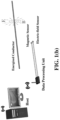
- FIGS. 1(a) and 1(b) schematically depict a system for anomaly detection according to an embodiment.
- Anomaly detection system 15 includes an electric-field sensor 20 and a magnetic-field sensor 30.
- the electric-field sensor may be selected from electric field meters, microelectromechanical sensors that measure the electric field strength in a free field, or fiber-optic electric-field sensor.
- An example of a suitable commercially-available device is ETS-Lindgren's Model HI-3638 VLF/ELF Electric Field Meter.
- the electric-field sensor/meter may be used to provide voltage information about a power system such as conductor 10 in FIG. 1(a) .
- the magnetic-field sensor may be selected from magnetic sensors including anisotropic magnetoresistive sensors, tunneling magnetoresistive sensors, giant magnetoresistive sensors, Hall-effect sensors etc.
- An example of a suitable, commercially-available sensor is TMR2307 from Multi-Dimension Technology Co. Ltd. This sensor uses three push-pull Wheatstone bridges and can measure weak magnetic fields and electric currents.
- the magnetic-field sensor may be used to provide current data about a power system. Both the electric-field sensor 20 and the magnetic-field sensor 30 are non-contact sensors and do not require any diversion of power from the conductor 10 in order to make their measurements.
- a data processing unit 35 communicates with the electric-field sensor 20 and the magnetic-field sensor 30.
- the data processing unit 35 comprises an analog-to-digital converter (ADC) module 40, a power supply 50, and a micro-controller 45 with optional wireless transmission capabilities for communication with a host processor 60.
- ADC analog-to-digital converter
- the electric- and magnetic-field sensors are positioned adjacent any kind of power system (e.g., overhead transmission lines, power distribution cables, and wiring systems in office and residential buildings) to measure electromagnetic fields emanating from the system to be monitored.
- the analog signals from sensors 20 and 30 are converted to digital signals in the ADC module 40. Analysis may be performed in the micro-controller unit 45; alternatively, analysis may be performed in a host system 60.
- the stored data in the data processing unit will be sent to an optional host 60 through an optional wireless connection.
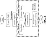
- the signals are measured at step 100. It is recommended to locate the electric- and magnetic-field sensors as close to the system to be monitored as possible in order to achieve the most accurate signal measurements. However, this proximity may also capture electromagnetic noise emanating from a variety of power devices nearby, which can interfere with the signal from the target being measured. Therefore, the measured signals are subject to de-noising, leading to filtered signals at position 110 in FIG. 2 .
- Feature extraction occurs at positions 120 and 130.
- a series of parameters are extracted to characterize the measured and filtered signals. For example, the maximum, minimum, and root mean square values of electric- and magnetic-field waveforms in a time cycle may be determined.
- Fourier analysis may also be performed. Regarding the measurement in power systems, a Fourier frequency spectrum is a good reference for identifying the signatures of signal patterns such as the magnitude of the frequency spectrum at DC, 50 Hz, 150 Hz, and so on. Then these data are constructed in an array to describe the signal measurement.
- Normalization 140 The normalization of the analyzed datasets is performed since the measured data are in different units (e.g., Tesla for magnetic fields, and V/m for electric fields) and sizes (e.g., the magnetic fields are in mini-Tesla, but the electric fields are in thousands V/m around for a 220 V conductor). Because anomaly detection involves analysis of Euclidian distances for different sets of data, normalization prepares the data for this analysis.
- units e.g., Tesla for magnetic fields, and V/m for electric fields
- sizes e.g., the magnetic fields are in mini-Tesla, but the electric fields are in thousands V/m around for a 220 V conductor.
- Anomaly identification 150 Computational intelligence is applied to the data resulting from the processes set forth above.
- density-based spatial clustering (DBSCAN) of applications with noise is performed.
- DBSCAN analysis does not require the user to specify the number of clusters in the data in advance.
- DBSCAN clustering is robust to outliers due to its processing with noise.
- DBSCAN Density-Based Spatial Clustering of Applications with Noise
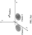
- DBSCAN involves creating n-dimensional shapes around a particular data point and determining how many data points fall within that shape. A sufficient number of data points means that the shape is a cluster. Clusters of high density (many data points) are distinguished from clusters of low density (fewer data points). By plotting the various data points and clustering the results based on the similarity of observation, points that are clearly outlying may be identified and investigated as outliers. For example, in FIG.
- cluster 1 is formed by data points collected in normal operation, then any data points which do not fall within cluster 1 are determined to be anomalies, such as data points in cluster 2.
- cluster 1 represents normal operation while cluster 2 represents one kind of anomaly which may be interruption. Meanwhile, there is a chance that some measurements are outliers due to measurement error, and hence corresponding data points are ignored and labeled as "outliers".
- the pseudo-code for implementing DBSCAN in this invention is shown in FIG. 3(b) .
- a user may specify the minimum number of points that are required to form a cluster (MinPts).
- the user may also specify the distance ⁇ that a neighborhood can be connected to the cluster.
- the user can define the severity of the power system condition to be recognized as an anomaly. The larger the selected ⁇ term, the less likely the condition is to be classified as an anomaly.
- simulations for two cases are performed, which are overhead transmission lines and the energy system in a multifamily residential building.
- FIG. 4 A three-phase overhead transmission system for delivering power is depicted in FIG. 4 .
- the span of transmission lines is 400 m
- the altitude of conductors at both ends is 30 m
- the spacing distance between phase conductors is 10 m
- the sagging distance of transmission lines (g in FIG. 4 ) is 5 m.
- condition #0 the voltage and current are in rated values
- condition #1 there is a slight voltage drop (-5%)
- condition #2 there is a slight voltage increase (+5%)
- condition #3 there is a slight current drop (-5%) by power changes at loading
- condition #4 there is a slight current rise (+5%) by the power changes at loading
- condition #5 there are large voltage and current variations due to the single phase-to-ground fault occurred.
- Single-phase wiring system is commonly used for delivering electricity to customers for most household appliances (e.g., lighting, fans) in residential buildings.
- electric- and magnetic-field sensors are located around one energized conductor in the residential building as depicted in FIG. 5 .
- the setting of the sensors related to the conductor is that the distance between the live wire and the sensors (d) is 1 cm, the distance between adjacent sensors (s) is 10 cm, and the distance between a live and a neutral wire is 10 cm (D > > d).
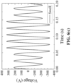
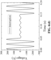
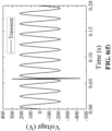
- a series of different power qualities is simulated on the live wire starting from 0.05 s in FIGs. 6(a)-(h) , including FIG. 6(a) standard, FIG. 6(b) sag, FIG.
- FIG. 6(c) swell FIG. 6(d) interruption
- FIG. 6(e) harmonic FIG. 6(f) transient
- FIG. 6(g) sag + harmonic FIG. 6(h) swell + harmonic.
- two more conditions are given for voltage variations at ⁇ 5%.
- the loading is resistive, and thus the current changes in the same way as voltage. Totally, there are ten conditions in this case.
- the measurements from the electric- and magnetic-field sensors in the simulation are recorded in a time cycle from 0.05 to 0.07 s, and their Fourier frequency spectrum is analyzed.
- the maximum and minimum values, and the amplitudes of the frequency spectrum at 50, 150 and 250 Hz after being normalized are chosen to represent the dataset.
- the results in Table III show that the conditions under a standard voltage waveform including its variation of ⁇ 5% are clustered into the same group, indicating they are the normal operating status of the energy system.
- Conditions other than the standard condition are classified into different groups. This means that the anomalies are identified for other conditions based on the group number shown in Table III (for conditions which do not belong to cluster #1).
- the electromagnetic-sensing-based technique using computational intelligence for anomaly detection in energy systems can monitor the electrical states of energy systems, including voltages and currents, and identify the anomaly conditions even with no prior knowledge of the number of anomaly categories.
- the technique is non-intrusive to energy systems due to its contactless electromagnetic sensing, which makes installation work of the invention from this technique easy and safe.
- Simulations of various power quality disturbances successfully verify the proposed technique.
- the combinations of multi-power quality disturbances are also studied, and the proposed technique is still capable of detecting the anomalies without mixing with other anomalies.
- This method needs a relatively small number of preset values. Only MinPts and ⁇ are set in advance and can be selected to provide a threshold level to a detected anomaly.
- the system of the present invention can work powerfully with the aid of big data technology/large-scale machine learning to improve the overall power quality of energy systems.
- the proposed techniques are even able to categorize different kinds of anomaly conditions with the special patterns of anomalies recorded from big data technology. Therefore, the proposed technique is promising due to its easy installation, large detection capability, and robustness.
Landscapes
- Engineering & Computer Science (AREA)
- Power Engineering (AREA)
- Physics & Mathematics (AREA)
- General Physics & Mathematics (AREA)
- Remote Monitoring And Control Of Power-Distribution Networks (AREA)
Claims (14)
- Anomaliedetektor für Energiesysteme, umfassend:eine Reihe von kontaktlosen Magnetfeldsensoren zum Produzieren von Magnetfeldsignalen, die Betriebsströme in einem Energiesystem angeben;eine Reihe von kontaktlosen elektrischen Feldsensoren zum Produzieren von elektrischen Feldsignalen, die Betriebsspannungen in dem Energiesystem angeben;einen Analog-Digital-Wandler zum Umwandeln der Strom- und Spannungssignale in digitale Signale;einen Filter zum Entfernen von Rauschen aus den Strom- und Spannungssignalen,einen Merkmalsextraktor zum Extrahieren von Merkmalen aus den Strom- und Spannungssignalen, um Messparameter jedes Signals zu kennzeichnen;einen Datenprozessor, der konfiguriert ist, um Daten-Clustering von extrahierten Merkmalen durchzuführen;einen Anomalieindikator, der eine Anomalie aus einem oder mehreren Datenpunkten identifiziert, die nicht in einen Cluster fallen, der Normalbedingungen angibt.
- Anomaliedetektor für Energiesysteme nach Anspruch 1, wobei j eder Magnetfeldsensor aus einem anisotropen magnetoresistiven Sensor, einem tunnelmagnetoresistiven Sensor, einem riesigen magnetoresistiven Sensor oder einem Hall-Effekt-Sensor ausgewählt ist.
- Anomaliedetektor für Energiesysteme nach Anspruch 1, wobei jeder elektrische Feldsensor aus einem mikroelektromechanischen Sensor, einem faseroptischen elektrischen Feldsensor oder einem elektrischen Feldmesser ausgewählt ist.
- Anomaliedetektor für Energiesysteme nach Anspruch 1, wobei das Daten-Clustering unter Verwendung von Density-Based Spatial Clustering of Applications with Noise (DBSCAN) unter Verwendung einer ausgewählten Mindestanzahl an Punkten zum Bilden eines Clusters und eines Parameters, der den Abstand zwischen verschiedenen Clustern angibt, basierend auf einem Datensatzmerkmal aus Magnet- und elektrischen Feldmessungen durchgeführt wird.
- Anomaliedetektor für Energiesysteme nach Anspruch 1, ferner umfassend einen drahtlosen Sender zum Verbinden mit einer Host-Vorrichtung.
- Verfahren zur Anomaliedetektion in Energiesystemen, umfassend:kontaktloses Erfassen eines Magnetfeldes eines Energiesystems unter Verwendung eines kontaktlosen Magnetfeldsensors, um ein Magnetfeldsignal zu produzieren, das den Betriebsstrom in dem Energiesystem angibt,kontaktloses Erfassen eines elektrischen Feldes eines Energiesystems unter Verwendung eines kontaktlosen elektrischen Feldsensors zum Produzieren eines elektrischen Feldsignals, das die Betriebsspannung in dem Energiesystem angibt;Filtern des Magnetfeldsignals und der elektrischen Feldsignale zum Entfernen von elektromagnetischen Feldern in dem Hintergrund, die nicht von dem Energiesystem erzeugt werden;Extrahieren von Merkmalen aus den Magnetfeldsignalen und den elektrischen Feldsignalen zum Kennzeichnen von Parametern jedes Signals;Durchführen von Daten-Clustering von extrahierten Merkmalen;Identifizieren einer Anomalie aus einem oder mehreren Datenpunkten, die nicht in einen Cluster fallen, der Normalbedingungen angibt.
- Verfahren zur Anomaliedetektion in Energiesystemen nach Anspruch 6, wobei das Daten-Clustering von extrahierten Merkmalen unter Verwendung eines Algorithmus des Density-Based Spatial Clustering of Applications with Noise (DBSCAN), der eine ausgewählte Mindestanzahl an Punkten zum Bilden eines Clusters verwendet, und eines Parameters, der einen Abstand zwischen verschiedenen Clustern basierend auf einem Datensatzmerkmal angibt, durchgeführt wird.
- Verfahren zur Anomaliedetektion in Energiesystemen nach Anspruch 6, wobei das Energiesystem aus einem Übertragungssystem oder einem elektrischen Kabel für Privathaushalte ausgewählt ist.
- Verfahren zur Anomaliedetektion in Energiesystemen nach Anspruch 6, wobei der Magnetfeldsensor aus einem anisotropen magnetoresistiven Sensor, einem tunnelmagnetoresistiven Sensor, einem riesigen magnetoresistiven Sensor oder einem Hall-Effekt-Sensor ausgewählt ist.
- Verfahren zur Anomaliedetektion in Energiesystemen nach Anspruch 6, wobei der elektrische Feldsensor aus einem mikroelektromechanischen Sensor, einem faseroptischen elektrischen Feldsensor oder einem elektrischen Feldmesser ausgewählt ist.
- Verfahren zur Anomaliedetektion in Energiesystemen nach Anspruch 6, wobei die Merkmalsextraktion Analyse eines Fourier-Frequenzspektrums des elektrischen Signals und/oder des Magnetsignals beinhaltet.
- Verfahren zur Anomaliedetektion in Energiesystemen nach Anspruch 6, wobei die Merkmalsextraktion Analysieren eines Maximal-, Minimal- und Effektivwertes von elektrischer und Magnetfeldmessung von elektromagnetischen Sensoren in einem Zeitzyklus und eines Frequenzspektrums in Grund- und harmonischer Frequenz beinhaltet.
- Verfahren zur Anomaliedetektion in Energiesystemen nach Anspruch 6, wobei die kontaktlose Erfassung eines Magnetfeldes eines Energiesystems eine Reihe von kontaktlosen Magnetfeldsensoren einsetzt.
- Verfahren zur Anomaliedetektion in Energiesystemen nach Anspruch 6, wobei die kontaktlose Erfassung eines elektrischen Feldes eines Energiesystems eine Reihe von kontaktlosen elektrischen Feldsensoren einsetzt.
Applications Claiming Priority (1)
| Application Number | Priority Date | Filing Date | Title |
|---|---|---|---|
| PCT/IB2019/057684 WO2021048596A1 (en) | 2019-09-12 | 2019-09-12 | Anomaly detection in energy systems |
Publications (3)
| Publication Number | Publication Date |
|---|---|
| EP4005047A1 EP4005047A1 (de) | 2022-06-01 |
| EP4005047A4 EP4005047A4 (de) | 2023-05-31 |
| EP4005047B1 true EP4005047B1 (de) | 2024-05-01 |
Family
ID=74866174
Family Applications (1)
| Application Number | Title | Priority Date | Filing Date |
|---|---|---|---|
| EP19945149.3A Active EP4005047B1 (de) | 2019-09-12 | 2019-09-12 | Anomaliedetektion in energiesystemen |
Country Status (4)
| Country | Link |
|---|---|
| US (1) | US12224585B2 (de) |
| EP (1) | EP4005047B1 (de) |
| CN (1) | CN114391204A (de) |
| WO (1) | WO2021048596A1 (de) |
Cited By (1)
| Publication number | Priority date | Publication date | Assignee | Title |
|---|---|---|---|---|
| US12228596B2 (en) | 2020-02-15 | 2025-02-18 | Remoni A/S | Power quality analysis system and method for monitoring from the outside of multiconductor cables |
Families Citing this family (3)
| Publication number | Priority date | Publication date | Assignee | Title |
|---|---|---|---|---|
| WO2023156019A1 (de) * | 2022-02-21 | 2023-08-24 | Energie Network Services Ag | Verfahren und vorrichtung zur überwachung einer energiereichen netzinfrastruktur |
| CN117977717B (zh) * | 2024-04-01 | 2024-06-11 | 国网黑龙江省电力有限公司佳木斯供电公司 | 一种寒地风光热储能综合能源协同管理方法及系统 |
| CN119577656B (zh) * | 2025-01-24 | 2025-05-13 | 甘肃瓦特电力科技有限公司 | 一种高压输电线路非接触电磁取电储能监管系统 |
Family Cites Families (19)
| Publication number | Priority date | Publication date | Assignee | Title |
|---|---|---|---|---|
| US6798263B1 (en) * | 2002-11-25 | 2004-09-28 | Applied Micro Circuits Corporation | Reset feature for a low voltage differential latch |
| US20090128119A1 (en) * | 2007-11-16 | 2009-05-21 | Fujitsu Microelectronics Limited | Differential output circuit |
| EP2241898B1 (de) * | 2008-02-06 | 2023-06-28 | Mitsubishi Electric Corporation | Messsystem für elektrische leistung und gerätesteuerungssystem |
| CA2871533C (en) * | 2012-03-13 | 2020-04-07 | Live Power Intelligence Company Na, Llc | Method and apparatus for monitoring electric power transmission, disturbances and forecasts |
| US10299149B2 (en) * | 2013-03-15 | 2019-05-21 | DGS Global Systems, Inc. | Systems, methods, and devices for electronic spectrum management |
| US9829516B1 (en) * | 2014-09-23 | 2017-11-28 | Amazon Technologies, Inc. | Non-intrusive transient power detection system |
| EP3362800A4 (de) * | 2015-10-16 | 2019-09-04 | Massachusetts Institute of Technology | Nichtintrusive überwachung |
| CN205301453U (zh) * | 2015-11-06 | 2016-06-08 | 广东电网有限责任公司电力科学研究院 | 一种变压器运行异常监测装置 |
| WO2017137964A1 (en) * | 2016-02-11 | 2017-08-17 | Live Power Intelligence Company Na, Llc | System and method of power grid monitoring |
| CN107543982A (zh) * | 2016-06-28 | 2018-01-05 | 国网天津市电力公司 | 面向低压用户的非侵入故障识别装置 |
| WO2018017508A1 (en) * | 2016-07-18 | 2018-01-25 | Peerbridge Health, Inc. | System and method for treating sleep apnea |
| CN106777984B (zh) * | 2016-12-19 | 2019-02-22 | 福州大学 | 一种基于密度聚类算法实现光伏阵列工作状态分析与故障诊断的方法 |
| CN106909664A (zh) * | 2017-02-28 | 2017-06-30 | 国网福建省电力有限公司 | 一种电力设备数据流故障识别方法 |
| CN107133318B (zh) * | 2017-05-03 | 2021-06-15 | 北京市交通信息中心 | 一种基于手机信令数据的人口识别方法 |
| CN106991508A (zh) * | 2017-05-25 | 2017-07-28 | 华北电力大学 | 一种基于dbscan的风电机组运行状态识别方法 |
| CN107846472A (zh) * | 2017-11-24 | 2018-03-27 | 华北电力大学(保定) | 大规模输变电设备监测数据流的快速异常检测方法 |
| CN108828406A (zh) * | 2018-06-19 | 2018-11-16 | 深圳安顺通电力物联服务有限公司 | 非侵入式用户用电的故障识别方法及其系统 |
| CN109298225B (zh) * | 2018-09-29 | 2020-10-09 | 国网四川省电力公司电力科学研究院 | 一种电压量测数据异常状态自动识别模型系统及方法 |
| CN109446193A (zh) * | 2018-11-13 | 2019-03-08 | 国网宁夏电力有限公司电力科学研究院 | 反窃电模型生成方法及装置 |
-
2019
- 2019-09-12 US US17/753,766 patent/US12224585B2/en active Active
- 2019-09-12 EP EP19945149.3A patent/EP4005047B1/de active Active
- 2019-09-12 WO PCT/IB2019/057684 patent/WO2021048596A1/en not_active Ceased
- 2019-09-12 CN CN201980100255.6A patent/CN114391204A/zh active Pending
Cited By (1)
| Publication number | Priority date | Publication date | Assignee | Title |
|---|---|---|---|---|
| US12228596B2 (en) | 2020-02-15 | 2025-02-18 | Remoni A/S | Power quality analysis system and method for monitoring from the outside of multiconductor cables |
Also Published As
| Publication number | Publication date |
|---|---|
| CN114391204A (zh) | 2022-04-22 |
| US12224585B2 (en) | 2025-02-11 |
| EP4005047A4 (de) | 2023-05-31 |
| EP4005047A1 (de) | 2022-06-01 |
| WO2021048596A1 (en) | 2021-03-18 |
| US20220376501A1 (en) | 2022-11-24 |
Similar Documents
| Publication | Publication Date | Title |
|---|---|---|
| CN109917221B (zh) | 用于三相配电电缆的故障分类的装置和方法 | |
| Bíscaro et al. | Integrated fault location and power-quality analysis in electric power distribution systems | |
| EP4005047B1 (de) | Anomaliedetektion in energiesystemen | |
| Gu et al. | High impedance fault detection in overhead distribution feeders using a DSP-based feeder terminal unit | |
| James et al. | Development of computer-based measurements and their application to PD pattern analysis | |
| Li et al. | A generic waveform abnormality detection method for utility equipment condition monitoring | |
| CN108181547B (zh) | 基于时间序列压缩的动态时间弯曲距离故障区段定位方法 | |
| US20200326385A1 (en) | Method for processing direct current electric arc and apparatus | |
| Jiang et al. | Machine learning approach to detect arc faults based on regular coupling features | |
| CN115136439A (zh) | 一种电网管理系统及方法 | |
| CN101726674B (zh) | 一种在线评估变电站绝缘在线监测系统的方法 | |
| CN115575856A (zh) | 输电电缆终端场中避雷器的泄露电流在线监测方法及系统 | |
| Ke et al. | A novel power transformer condition monitoring system based on wide-band measurement of core earth signals and correlation analysis with multi-source data | |
| CN113093085A (zh) | 站域电流互感器二次回路故障检测方法及装置 | |
| CN103777064A (zh) | 免外接交流电源的氧化锌避雷器带电检测装置 | |
| Liu et al. | Dc series arc fault detection based on random forest combined with entropy weight method | |
| CN113109664B (zh) | 一种基于小波奇异熵的电压暂降源定位方法 | |
| Lu et al. | Multiple disturbances classifier for electric signals using adaptive structuring neural networks | |
| Chen et al. | Identifying single‐phase to ground fault based on line multi‐dimensional data in cyber‐physical distribution system | |
| CN113848376A (zh) | 基于三相泄漏电流相角差的避雷器带电监测装置及方法 | |
| Saiprakash et al. | Fault Diagnosis in Micro Grid Using Wavelet Transform in Combination with Machine Learning | |
| Yu et al. | A Novel Bus Differential Protection Method Based on the Frequency-Dependent Evolution Mechanism of Fault-Current Traveling Waves | |
| Leinakse et al. | Processing and filtering digital fault recorder events for load model estimation | |
| CN120949119B (zh) | 一种输电线路单相断线故障检测方法及系统 | |
| Wang et al. | Fault section location method for distribution network based on combination of magnetic field and VMD-HHT |
Legal Events
| Date | Code | Title | Description |
|---|---|---|---|
| STAA | Information on the status of an ep patent application or granted ep patent |
Free format text: STATUS: THE INTERNATIONAL PUBLICATION HAS BEEN MADE |
|
| PUAI | Public reference made under article 153(3) epc to a published international application that has entered the european phase |
Free format text: ORIGINAL CODE: 0009012 |
|
| STAA | Information on the status of an ep patent application or granted ep patent |
Free format text: STATUS: REQUEST FOR EXAMINATION WAS MADE |
|
| 17P | Request for examination filed |
Effective date: 20220224 |
|
| AK | Designated contracting states |
Kind code of ref document: A1 Designated state(s): AL AT BE BG CH CY CZ DE DK EE ES FI FR GB GR HR HU IE IS IT LI LT LU LV MC MK MT NL NO PL PT RO RS SE SI SK SM TR |
|
| DAV | Request for validation of the european patent (deleted) | ||
| DAX | Request for extension of the european patent (deleted) | ||
| A4 | Supplementary search report drawn up and despatched |
Effective date: 20230504 |
|
| RIC1 | Information provided on ipc code assigned before grant |
Ipc: H02J 13/00 20060101ALI20230427BHEP Ipc: G01R 13/00 20060101ALI20230427BHEP Ipc: H02J 3/12 20060101AFI20230427BHEP |
|
| GRAP | Despatch of communication of intention to grant a patent |
Free format text: ORIGINAL CODE: EPIDOSNIGR1 |
|
| STAA | Information on the status of an ep patent application or granted ep patent |
Free format text: STATUS: GRANT OF PATENT IS INTENDED |
|
| INTG | Intention to grant announced |
Effective date: 20240124 |
|
| GRAS | Grant fee paid |
Free format text: ORIGINAL CODE: EPIDOSNIGR3 |
|
| GRAA | (expected) grant |
Free format text: ORIGINAL CODE: 0009210 |
|
| STAA | Information on the status of an ep patent application or granted ep patent |
Free format text: STATUS: THE PATENT HAS BEEN GRANTED |
|
| AK | Designated contracting states |
Kind code of ref document: B1 Designated state(s): AL AT BE BG CH CY CZ DE DK EE ES FI FR GB GR HR HU IE IS IT LI LT LU LV MC MK MT NL NO PL PT RO RS SE SI SK SM TR |
|
| REG | Reference to a national code |
Ref country code: GB Ref legal event code: FG4D |
|
| REG | Reference to a national code |
Ref country code: CH Ref legal event code: EP |
|
| REG | Reference to a national code |
Ref country code: IE Ref legal event code: FG4D |
|
| REG | Reference to a national code |
Ref country code: DE Ref legal event code: R096 Ref document number: 602019051772 Country of ref document: DE |
|
| REG | Reference to a national code |
Ref country code: LT Ref legal event code: MG9D |
|
| REG | Reference to a national code |
Ref country code: NL Ref legal event code: MP Effective date: 20240501 |
|
| PG25 | Lapsed in a contracting state [announced via postgrant information from national office to epo] |
Ref country code: IS Free format text: LAPSE BECAUSE OF FAILURE TO SUBMIT A TRANSLATION OF THE DESCRIPTION OR TO PAY THE FEE WITHIN THE PRESCRIBED TIME-LIMIT Effective date: 20240901 |
|
| PG25 | Lapsed in a contracting state [announced via postgrant information from national office to epo] |
Ref country code: BG Free format text: LAPSE BECAUSE OF FAILURE TO SUBMIT A TRANSLATION OF THE DESCRIPTION OR TO PAY THE FEE WITHIN THE PRESCRIBED TIME-LIMIT Effective date: 20240501 |
|
| PG25 | Lapsed in a contracting state [announced via postgrant information from national office to epo] |
Ref country code: HR Free format text: LAPSE BECAUSE OF FAILURE TO SUBMIT A TRANSLATION OF THE DESCRIPTION OR TO PAY THE FEE WITHIN THE PRESCRIBED TIME-LIMIT Effective date: 20240501 Ref country code: FI Free format text: LAPSE BECAUSE OF FAILURE TO SUBMIT A TRANSLATION OF THE DESCRIPTION OR TO PAY THE FEE WITHIN THE PRESCRIBED TIME-LIMIT Effective date: 20240501 |
|
| PG25 | Lapsed in a contracting state [announced via postgrant information from national office to epo] |
Ref country code: GR Free format text: LAPSE BECAUSE OF FAILURE TO SUBMIT A TRANSLATION OF THE DESCRIPTION OR TO PAY THE FEE WITHIN THE PRESCRIBED TIME-LIMIT Effective date: 20240802 |
|
| PG25 | Lapsed in a contracting state [announced via postgrant information from national office to epo] |
Ref country code: PT Free format text: LAPSE BECAUSE OF FAILURE TO SUBMIT A TRANSLATION OF THE DESCRIPTION OR TO PAY THE FEE WITHIN THE PRESCRIBED TIME-LIMIT Effective date: 20240902 |
|
| REG | Reference to a national code |
Ref country code: AT Ref legal event code: MK05 Ref document number: 1683737 Country of ref document: AT Kind code of ref document: T Effective date: 20240501 |
|
| PG25 | Lapsed in a contracting state [announced via postgrant information from national office to epo] |
Ref country code: NL Free format text: LAPSE BECAUSE OF FAILURE TO SUBMIT A TRANSLATION OF THE DESCRIPTION OR TO PAY THE FEE WITHIN THE PRESCRIBED TIME-LIMIT Effective date: 20240501 |
|
| PG25 | Lapsed in a contracting state [announced via postgrant information from national office to epo] |
Ref country code: ES Free format text: LAPSE BECAUSE OF FAILURE TO SUBMIT A TRANSLATION OF THE DESCRIPTION OR TO PAY THE FEE WITHIN THE PRESCRIBED TIME-LIMIT Effective date: 20240501 |
|
| PG25 | Lapsed in a contracting state [announced via postgrant information from national office to epo] |
Ref country code: AT Free format text: LAPSE BECAUSE OF FAILURE TO SUBMIT A TRANSLATION OF THE DESCRIPTION OR TO PAY THE FEE WITHIN THE PRESCRIBED TIME-LIMIT Effective date: 20240501 |
|
| PG25 | Lapsed in a contracting state [announced via postgrant information from national office to epo] |
Ref country code: PL Free format text: LAPSE BECAUSE OF FAILURE TO SUBMIT A TRANSLATION OF THE DESCRIPTION OR TO PAY THE FEE WITHIN THE PRESCRIBED TIME-LIMIT Effective date: 20240501 |
|
| PG25 | Lapsed in a contracting state [announced via postgrant information from national office to epo] |
Ref country code: LV Free format text: LAPSE BECAUSE OF FAILURE TO SUBMIT A TRANSLATION OF THE DESCRIPTION OR TO PAY THE FEE WITHIN THE PRESCRIBED TIME-LIMIT Effective date: 20240501 |
|
| PG25 | Lapsed in a contracting state [announced via postgrant information from national office to epo] |
Ref country code: PT Free format text: LAPSE BECAUSE OF FAILURE TO SUBMIT A TRANSLATION OF THE DESCRIPTION OR TO PAY THE FEE WITHIN THE PRESCRIBED TIME-LIMIT Effective date: 20240902 Ref country code: PL Free format text: LAPSE BECAUSE OF FAILURE TO SUBMIT A TRANSLATION OF THE DESCRIPTION OR TO PAY THE FEE WITHIN THE PRESCRIBED TIME-LIMIT Effective date: 20240501 Ref country code: NO Free format text: LAPSE BECAUSE OF FAILURE TO SUBMIT A TRANSLATION OF THE DESCRIPTION OR TO PAY THE FEE WITHIN THE PRESCRIBED TIME-LIMIT Effective date: 20240801 Ref country code: NL Free format text: LAPSE BECAUSE OF FAILURE TO SUBMIT A TRANSLATION OF THE DESCRIPTION OR TO PAY THE FEE WITHIN THE PRESCRIBED TIME-LIMIT Effective date: 20240501 Ref country code: LV Free format text: LAPSE BECAUSE OF FAILURE TO SUBMIT A TRANSLATION OF THE DESCRIPTION OR TO PAY THE FEE WITHIN THE PRESCRIBED TIME-LIMIT Effective date: 20240501 Ref country code: IS Free format text: LAPSE BECAUSE OF FAILURE TO SUBMIT A TRANSLATION OF THE DESCRIPTION OR TO PAY THE FEE WITHIN THE PRESCRIBED TIME-LIMIT Effective date: 20240901 Ref country code: HR Free format text: LAPSE BECAUSE OF FAILURE TO SUBMIT A TRANSLATION OF THE DESCRIPTION OR TO PAY THE FEE WITHIN THE PRESCRIBED TIME-LIMIT Effective date: 20240501 Ref country code: GR Free format text: LAPSE BECAUSE OF FAILURE TO SUBMIT A TRANSLATION OF THE DESCRIPTION OR TO PAY THE FEE WITHIN THE PRESCRIBED TIME-LIMIT Effective date: 20240802 Ref country code: FI Free format text: LAPSE BECAUSE OF FAILURE TO SUBMIT A TRANSLATION OF THE DESCRIPTION OR TO PAY THE FEE WITHIN THE PRESCRIBED TIME-LIMIT Effective date: 20240501 Ref country code: ES Free format text: LAPSE BECAUSE OF FAILURE TO SUBMIT A TRANSLATION OF THE DESCRIPTION OR TO PAY THE FEE WITHIN THE PRESCRIBED TIME-LIMIT Effective date: 20240501 Ref country code: BG Free format text: LAPSE BECAUSE OF FAILURE TO SUBMIT A TRANSLATION OF THE DESCRIPTION OR TO PAY THE FEE WITHIN THE PRESCRIBED TIME-LIMIT Effective date: 20240501 Ref country code: AT Free format text: LAPSE BECAUSE OF FAILURE TO SUBMIT A TRANSLATION OF THE DESCRIPTION OR TO PAY THE FEE WITHIN THE PRESCRIBED TIME-LIMIT Effective date: 20240501 Ref country code: RS Free format text: LAPSE BECAUSE OF FAILURE TO SUBMIT A TRANSLATION OF THE DESCRIPTION OR TO PAY THE FEE WITHIN THE PRESCRIBED TIME-LIMIT Effective date: 20240801 |
|
| PG25 | Lapsed in a contracting state [announced via postgrant information from national office to epo] |
Ref country code: DK Free format text: LAPSE BECAUSE OF FAILURE TO SUBMIT A TRANSLATION OF THE DESCRIPTION OR TO PAY THE FEE WITHIN THE PRESCRIBED TIME-LIMIT Effective date: 20240501 |
|
| PG25 | Lapsed in a contracting state [announced via postgrant information from national office to epo] |
Ref country code: EE Free format text: LAPSE BECAUSE OF FAILURE TO SUBMIT A TRANSLATION OF THE DESCRIPTION OR TO PAY THE FEE WITHIN THE PRESCRIBED TIME-LIMIT Effective date: 20240501 |
|
| PG25 | Lapsed in a contracting state [announced via postgrant information from national office to epo] |
Ref country code: CZ Free format text: LAPSE BECAUSE OF FAILURE TO SUBMIT A TRANSLATION OF THE DESCRIPTION OR TO PAY THE FEE WITHIN THE PRESCRIBED TIME-LIMIT Effective date: 20240501 |
|
| PG25 | Lapsed in a contracting state [announced via postgrant information from national office to epo] |
Ref country code: RO Free format text: LAPSE BECAUSE OF FAILURE TO SUBMIT A TRANSLATION OF THE DESCRIPTION OR TO PAY THE FEE WITHIN THE PRESCRIBED TIME-LIMIT Effective date: 20240501 Ref country code: SK Free format text: LAPSE BECAUSE OF FAILURE TO SUBMIT A TRANSLATION OF THE DESCRIPTION OR TO PAY THE FEE WITHIN THE PRESCRIBED TIME-LIMIT Effective date: 20240501 |
|
| PG25 | Lapsed in a contracting state [announced via postgrant information from national office to epo] |
Ref country code: SM Free format text: LAPSE BECAUSE OF FAILURE TO SUBMIT A TRANSLATION OF THE DESCRIPTION OR TO PAY THE FEE WITHIN THE PRESCRIBED TIME-LIMIT Effective date: 20240501 |
|
| PG25 | Lapsed in a contracting state [announced via postgrant information from national office to epo] |
Ref country code: SM Free format text: LAPSE BECAUSE OF FAILURE TO SUBMIT A TRANSLATION OF THE DESCRIPTION OR TO PAY THE FEE WITHIN THE PRESCRIBED TIME-LIMIT Effective date: 20240501 Ref country code: SK Free format text: LAPSE BECAUSE OF FAILURE TO SUBMIT A TRANSLATION OF THE DESCRIPTION OR TO PAY THE FEE WITHIN THE PRESCRIBED TIME-LIMIT Effective date: 20240501 Ref country code: RO Free format text: LAPSE BECAUSE OF FAILURE TO SUBMIT A TRANSLATION OF THE DESCRIPTION OR TO PAY THE FEE WITHIN THE PRESCRIBED TIME-LIMIT Effective date: 20240501 Ref country code: EE Free format text: LAPSE BECAUSE OF FAILURE TO SUBMIT A TRANSLATION OF THE DESCRIPTION OR TO PAY THE FEE WITHIN THE PRESCRIBED TIME-LIMIT Effective date: 20240501 Ref country code: DK Free format text: LAPSE BECAUSE OF FAILURE TO SUBMIT A TRANSLATION OF THE DESCRIPTION OR TO PAY THE FEE WITHIN THE PRESCRIBED TIME-LIMIT Effective date: 20240501 Ref country code: CZ Free format text: LAPSE BECAUSE OF FAILURE TO SUBMIT A TRANSLATION OF THE DESCRIPTION OR TO PAY THE FEE WITHIN THE PRESCRIBED TIME-LIMIT Effective date: 20240501 |
|
| REG | Reference to a national code |
Ref country code: DE Ref legal event code: R097 Ref document number: 602019051772 Country of ref document: DE |
|
| PG25 | Lapsed in a contracting state [announced via postgrant information from national office to epo] |
Ref country code: IT Free format text: LAPSE BECAUSE OF FAILURE TO SUBMIT A TRANSLATION OF THE DESCRIPTION OR TO PAY THE FEE WITHIN THE PRESCRIBED TIME-LIMIT Effective date: 20240501 |
|
| PLBE | No opposition filed within time limit |
Free format text: ORIGINAL CODE: 0009261 |
|
| STAA | Information on the status of an ep patent application or granted ep patent |
Free format text: STATUS: NO OPPOSITION FILED WITHIN TIME LIMIT |
|
| 26N | No opposition filed |
Effective date: 20250204 |
|
| PG25 | Lapsed in a contracting state [announced via postgrant information from national office to epo] |
Ref country code: SI Free format text: LAPSE BECAUSE OF FAILURE TO SUBMIT A TRANSLATION OF THE DESCRIPTION OR TO PAY THE FEE WITHIN THE PRESCRIBED TIME-LIMIT Effective date: 20240501 Ref country code: MC Free format text: LAPSE BECAUSE OF FAILURE TO SUBMIT A TRANSLATION OF THE DESCRIPTION OR TO PAY THE FEE WITHIN THE PRESCRIBED TIME-LIMIT Effective date: 20240501 |
|
| REG | Reference to a national code |
Ref country code: CH Ref legal event code: PL |
|
| PG25 | Lapsed in a contracting state [announced via postgrant information from national office to epo] |
Ref country code: LU Free format text: LAPSE BECAUSE OF NON-PAYMENT OF DUE FEES Effective date: 20240912 |
|
| REG | Reference to a national code |
Ref country code: BE Ref legal event code: MM Effective date: 20240930 |
|
| PG25 | Lapsed in a contracting state [announced via postgrant information from national office to epo] |
Ref country code: BE Free format text: LAPSE BECAUSE OF NON-PAYMENT OF DUE FEES Effective date: 20240930 |
|
| PG25 | Lapsed in a contracting state [announced via postgrant information from national office to epo] |
Ref country code: FR Free format text: LAPSE BECAUSE OF NON-PAYMENT OF DUE FEES Effective date: 20240930 |
|
| PG25 | Lapsed in a contracting state [announced via postgrant information from national office to epo] |
Ref country code: CH Free format text: LAPSE BECAUSE OF NON-PAYMENT OF DUE FEES Effective date: 20240930 |
|
| PG25 | Lapsed in a contracting state [announced via postgrant information from national office to epo] |
Ref country code: IE Free format text: LAPSE BECAUSE OF NON-PAYMENT OF DUE FEES Effective date: 20240912 |
|
| PG25 | Lapsed in a contracting state [announced via postgrant information from national office to epo] |
Ref country code: SE Free format text: LAPSE BECAUSE OF FAILURE TO SUBMIT A TRANSLATION OF THE DESCRIPTION OR TO PAY THE FEE WITHIN THE PRESCRIBED TIME-LIMIT Effective date: 20240501 |
|
| PGFP | Annual fee paid to national office [announced via postgrant information from national office to epo] |
Ref country code: DE Payment date: 20250730 Year of fee payment: 7 |
|
| PGFP | Annual fee paid to national office [announced via postgrant information from national office to epo] |
Ref country code: GB Payment date: 20250731 Year of fee payment: 7 |
|
| PG25 | Lapsed in a contracting state [announced via postgrant information from national office to epo] |
Ref country code: CY Free format text: LAPSE BECAUSE OF FAILURE TO SUBMIT A TRANSLATION OF THE DESCRIPTION OR TO PAY THE FEE WITHIN THE PRESCRIBED TIME-LIMIT; INVALID AB INITIO Effective date: 20190912 |
|
| PG25 | Lapsed in a contracting state [announced via postgrant information from national office to epo] |
Ref country code: HU Free format text: LAPSE BECAUSE OF FAILURE TO SUBMIT A TRANSLATION OF THE DESCRIPTION OR TO PAY THE FEE WITHIN THE PRESCRIBED TIME-LIMIT; INVALID AB INITIO Effective date: 20190912 |