EP3723213B1 - Schienenelement für beleuchtungssysteme und beleuchtungssystem mit diesem schienenelement - Google Patents
Schienenelement für beleuchtungssysteme und beleuchtungssystem mit diesem schienenelement Download PDFInfo
- Publication number
- EP3723213B1 EP3723213B1 EP20169112.8A EP20169112A EP3723213B1 EP 3723213 B1 EP3723213 B1 EP 3723213B1 EP 20169112 A EP20169112 A EP 20169112A EP 3723213 B1 EP3723213 B1 EP 3723213B1
- Authority
- EP
- European Patent Office
- Prior art keywords
- rail element
- channel
- shell
- along
- axis
- Prior art date
- Legal status (The legal status is an assumption and is not a legal conclusion. Google has not performed a legal analysis and makes no representation as to the accuracy of the status listed.)
- Active
Links
Images

Classifications
-
- F—MECHANICAL ENGINEERING; LIGHTING; HEATING; WEAPONS; BLASTING
- F21—LIGHTING
- F21S—NON-PORTABLE LIGHTING DEVICES; SYSTEMS THEREOF; VEHICLE LIGHTING DEVICES SPECIALLY ADAPTED FOR VEHICLE EXTERIORS
- F21S8/00—Lighting devices intended for fixed installation
- F21S8/04—Lighting devices intended for fixed installation intended only for mounting on a ceiling or the like overhead structures
- F21S8/043—Lighting devices intended for fixed installation intended only for mounting on a ceiling or the like overhead structures mounted by means of a rigid support, e.g. bracket or arm
-
- F—MECHANICAL ENGINEERING; LIGHTING; HEATING; WEAPONS; BLASTING
- F21—LIGHTING
- F21S—NON-PORTABLE LIGHTING DEVICES; SYSTEMS THEREOF; VEHICLE LIGHTING DEVICES SPECIALLY ADAPTED FOR VEHICLE EXTERIORS
- F21S8/00—Lighting devices intended for fixed installation
- F21S8/04—Lighting devices intended for fixed installation intended only for mounting on a ceiling or the like overhead structures
- F21S8/06—Lighting devices intended for fixed installation intended only for mounting on a ceiling or the like overhead structures by suspension
- F21S8/066—Lighting devices intended for fixed installation intended only for mounting on a ceiling or the like overhead structures by suspension from a light track
-
- F—MECHANICAL ENGINEERING; LIGHTING; HEATING; WEAPONS; BLASTING
- F21—LIGHTING
- F21V—FUNCTIONAL FEATURES OR DETAILS OF LIGHTING DEVICES OR SYSTEMS THEREOF; STRUCTURAL COMBINATIONS OF LIGHTING DEVICES WITH OTHER ARTICLES, NOT OTHERWISE PROVIDED FOR
- F21V21/00—Supporting, suspending, or attaching arrangements for lighting devices; Hand grips
- F21V21/34—Supporting elements displaceable along a guiding element
- F21V21/35—Supporting elements displaceable along a guiding element with direct electrical contact between the supporting element and electric conductors running along the guiding element
-
- H—ELECTRICITY
- H01—ELECTRIC ELEMENTS
- H01R—ELECTRICALLY-CONDUCTIVE CONNECTIONS; STRUCTURAL ASSOCIATIONS OF A PLURALITY OF MUTUALLY-INSULATED ELECTRICAL CONNECTING ELEMENTS; COUPLING DEVICES; CURRENT COLLECTORS
- H01R25/00—Coupling parts adapted for simultaneous co-operation with two or more identical counterparts, e.g. for distributing energy to two or more circuits
- H01R25/14—Rails or bus-bars constructed so that the counterparts can be connected thereto at any point along their length
- H01R25/145—Details, e.g. end pieces or joints
-
- F—MECHANICAL ENGINEERING; LIGHTING; HEATING; WEAPONS; BLASTING
- F21—LIGHTING
- F21Y—INDEXING SCHEME ASSOCIATED WITH SUBCLASSES F21K, F21L, F21S and F21V, RELATING TO THE FORM OR THE KIND OF THE LIGHT SOURCES OR OF THE COLOUR OF THE LIGHT EMITTED
- F21Y2115/00—Light-generating elements of semiconductor light sources
- F21Y2115/10—Light-emitting diodes [LED]
Definitions
- the invention relates to a rail element for lighting systems and to a lighting system comprising said rail element.
- the invention is particularly suited to manufacture - by way of example, but not exclusively - linear lighting systems, namely lighting systems extending along a linear path, which is not necessarily straight, but can also follow different geometric shapes, in particular also curved ones.
- rail lighting systems are widely used.
- one or more lamps for example of the spotlight type, are mounted on a longitudinal rail element, which is usually embedded in a ceiling.
- the rail elements normally consist of rigid elements, for example straight metal section bars. Therefore, the geometry of lighting systems of this type is limited to straight arrangements.
- WO2016132361A1 and US7883247B2 disclose rectilinear rail elements made of extruded aluminum.
- US2004/218395A1 discloses a lighting track apparatus which includes elongated colored tubes which are made of soft annealed aluminum and are easily bent into stable curved shapes to custom shape and fit sections of the apparatus into a track lighting system.
- Plural elongated electrical conductors preferably made of soft annealed copper, are mechanically flexible and able to support low voltage lighting currents without significant temperature rise.
- An elongated non-conducting mechanical support, made of plastics, is highly flexible so as to accept the shape of the tubes when bent. It engages with the tubes and the electrical conductors, whereby, the apparatus is easily formed into a curved shape that retains a selected curvature.
- a lamp or other appliance can be mounted on the apparatus, electrically contacting the conductors for power.
- curved rail elements can be manufactured, they need to be especially manufactured for each single purpose and be installed exactly in the original configuration, with no possibility of changes upon installation and set up of the lighting system.
- known rail elements for they have to house the cables needed to power and control the light sources, have dimensions, in particular a thickness or a height, which are relatively large and, anyway, exceed the standard thickness of plasterboard, which is used for the typical false ceilings where rail lighting systems are usually installed.
- the object of the invention is to provide a rail element for lighting systems and a lighting system comprising said rail element which are not affected by the drawbacks of the prior art discussed above.
- the invention relates to a rail element for lighting systems and to a lighting system comprising said rail element as defined, in essential terms, in appended claims 1 and 5, respectively.
- the rail element according to the invention has a structure and a configuration which turn out to be particularly efficient and allow dimensions to be contained, in particular in terms of height, so as to also adapt to the standard sizes of usual plasterboard false ceilings, thus allowing the rail element to be installed without interventions for the adjustment of the false ceiling.
- the particular arrangement of the conductive tracks allows, always with extremely reduced sizes and dimensions, for the use of cables with a significant (i.e. relatively large) cross section, so as to avoid possible problems of voltage drops along the rail element.
- the rail element is made of a material which is plastically cold-deformable, in particular can be bent, on the construction site, namely upon installation and, hence set up of the lighting system.
- the bending can be carried out by means of a hand-operated calender, namely in a simple, quick and precise manner.
- the desired curved shape can thus be directly obtained in the place where it has to be installed.
- the rail element according to the invention can fit not only lighting devices of different types (lamps, spotlights, LED strips, etcetera), but also apparatuses and accessories of other types, such as sensors, speakers, etcetera.
- the rail element according to the invention can be provided with a different number of conductive tracks, which be used, besides for the supply of power to the different devices installed on the rail element, for the transmission of data and, hence, for instance, for the control of the devices.
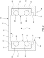
- number 1 indicates a rail lighting system extending along a linear path or axis, not necessarily a straight one, but also following different geometric shaped, in particular even curved shapes.
- the lighting system 1 comprises a rail element 10 and one or more lighting devices 11 (shown in figure 1 only schematically) supported by the rail element 10 and provided with light sources, for example lamps, spotlights, LED strips, etcetera.
- the lighting system 1 can comprise a plurality of rail elements 10 connected to one another, as it is often the case for systems of this type. Therefore, the rail element 10 defines a modular element of the lighting system 1, which can be combined with other similar rail elements in order to form the lighting system 1, with the aid of joining elements (which are not shown).
- modularity means an electrical-mechanical connection with continuity between different rail portions.
- the rail element 10 comprises a bar body 12 extending along a longitudinal axis A.
- the body 12 is a hollow body provided with a longitudinal inner channel 13 along the axis A, which is delimited by a bottom wall 14 and by two opposite lateral sides 15, which originate from respective sides of the bottom wall 14.
- the channel 13 is provided with a front opening 16 made in a front surface 17a of the body 12 and longitudinally extending along the channel 13 and, hence, along the entire body 12.
- the opening 16 faces the bottom wall 14 and is laterally delimited by respective longitudinal edges 18, which project towards one another from respective sides 15.
- the body 12 has a substantially quadrangular cross section, in particular a rectangular cross section, and the bottom wall 14 is substantially perpendicular to the sides 15 and parallel to the edges 18.
- the shape of the cross section of the body 12 can be different from the one described and show herein by mere way of example and the bottom wall 14, the sides 15 and the edges 18 can be differently shaped and oriented.
- the body 12 has a thickness of no more than 12.5 mm, measured as maximum distance between the front surface 17a where the opening 16 is formed and a rear surface 17b opposite it, which is defined by the outer surface of the bottom wall 14.
- the opposite surfaces 17a, 17b are flat and parallel and, therefore, the thickness of the body 12 between the surfaces 17a, 17b is the same in any point of the surfaces 17a, 17b.
- edges 18 have respective inner recesses 19 facing the channel 13 ad extending along the edges 18 parallel to the axis A.
- the channel 13 defines a seat for the lighting devices 11 ( figure 1 ).
- the recesses 19 define respective coupling seats, which can be engaged by respective coupling members of the lighting devices 11, which can optionally slide along the channel 13.
- the body 12 is an extruded section bar made of aluminium or of an aluminium alloy, which is cold bendable by means of a hand-operated calender.
- the body 12 (and, hence, the rail element 10 as a whole) can be bent around a bending axis, which is perpendicular to the axis A, so as to gain a curved shape along the axis A.
- the possibility of bending the body 12 and, hence, the rail element 10 as a whole is the result of the thermal treatment to which the body 12 is subjected after the extrusion of the aluminium (also meaning aluminium alloy, as it is common in the field).
- the body 12 is made of annealed aluminium.
- the body 12 is preferably provided in a T4 physical state (basically, without artificial ageing).
- the body 12 is made of EN AW-6060 aluminium, T4 state.
- radius of curvature (mm) bending angle 50 45° 100 90° 200 135° 400 180°
- the rail element 10 is manufactured and supplied to installers in a straight shape, namely with the body 12 extending along a straight axis A.
- the body 12 is bent to the desired shape, by means of a simple hand-operated calender.
- the rail element 10 houses a pair of longitudinal insulating shells 21, which extend parallel to the axis A and are made of an insulating material, for example a polymer material.
- the shells 21 are housed in the channel 13 along respective sides 15 and extend parallel to one another and to the axis A; the shells 21 have respective faces 22 facing one another in the channel 13.
- Each shell 21 is provided with or more conductive tracks 25, which extend along the channel 13 parallel to the axis A.
- the tracks 25 are made of a conductor material, for example a metal material.
- the tracks 25 are, for example, in form of cables or bars.
- Each track 25 is partially embedded in the respective shell 21 and projects from the face 22 of the shell 21, having an exposed portion 26, which longitudinally extends parallel to the axis A along the channel 13.
- each shell 21 is provided with a pair of conductive tracks 25, which extend side by side one above the other and are separated by the insulating material of the shell 21.
- the rail element 10 is provided with two pairs of conductive tracks 25 arranged along respective opposite lateral sides 15 of the channel 13.
- a pair of tracks 25 is used to electrically power the lighting devices 11 (namely, it supplies power), while the other pair of tracks 25 carries signals (data) to be used, for instance, for the control of the lighting devices 11.
- the portions 26 are available to come into contact with electrical contacts of the lighting devices 11.
- the rail element 10 can include a different number of tracks 26 arranged in a different manner from the one described and shown herein by mere way of example.
Landscapes
- Engineering & Computer Science (AREA)
- General Engineering & Computer Science (AREA)
- Arrangement Of Elements, Cooling, Sealing, Or The Like Of Lighting Devices (AREA)
- Circuit Arrangements For Discharge Lamps (AREA)
Claims (4)
- Schienenelement (10) für Beleuchtungssysteme,
umfassend einen Stabkörper (12), der sich entlang einer Längsachse (A) erstreckt und mit einem inneren Längskanal (13) entlang der Achse (A) versehen ist und an einer vorderen Oberfläche (17a) des Körpers (12) offen ist, und zwei gegenüberliegende Isolierschalen (21), die aus einem Isoliermaterial bestehen und in dem Kanal (13) entlang jeweils gegenüberliegender Seiten (15) des Kanals (13) angeordnet sind und sich parallel zueinander und zur Achse (A) erstrecken; wobei jede der Schalen (21) mit einer oder mehreren Leiterbahnen (25) versehen ist, die sich entlang einer jeweiligen Seite (15) des Kanals (13) parallel zur Achse (A) erstrecken; wobei der Körper (12) ein Hohlkörper ist und der Kanal (13) durch eine Bodenwand (14) und durch die beiden gegenüberliegenden Seiten (15) begrenzt ist, die von den jeweiligen Seiten der Bodenwand (14) ausgehen; der Kanal (13) mit einer vorderen Öffnung (16) versehen ist, die in einer vorderen Oberfläche (17a) des Körpers (12) ausgebildet ist und sich in Längsrichtung entlang des Kanals (13) und entlang des gesamten Körpers (12) erstreckt und der Bodenwand (14) zugewandt ist und seitlich durch jeweilige Längskanten (18) begrenzt ist, die sich von den jeweiligen Seiten (15) aufeinander zu erstrecken; dadurch gekennzeichnet, dass der Körper (12) ein extrudierter Profilstab aus getempertem Aluminium oder einer getemperten Aluminiumlegierung ist, der mittels eines manuellen Kalanders kalt biegbar ist, und dass der Körper (12) eine Dicke von nicht mehr als 12,5 mm aufweist, gemessen als der maximale Abstand zwischen der vorderen Oberfläche (17a), die mit der Öffnung (16) versehen ist, und einer hinteren Oberfläche (17b), die der vorderen Oberfläche (17a) gegenüberliegt und durch die äußere Oberfläche der Bodenwand (14) definiert ist. - Schienenelement nach Anspruch 1, wobei jede der Schalen (21) mit einem Paar der Leiterbahnen (25) versehen ist, die parallel zueinander und übereinander verlaufen und durch das Isoliermaterial der Schale (21) voneinander getrennt sind.
- Schienenelement nach Anspruch 1 oder 2, wobei die Schalen (21) jeweilige Flächen (22) aufweisen, die in dem Kanal (13) einander zugewandt sind; und jede der Bahnen (25) teilweise in die jeweilige Schale (21) eingebettet ist und von der Fläche (22) der Schale (21) hervorsteht, die der gegenüberliegenden Schale (21) zugewandt ist, und einen freiliegenden Abschnitt (26) aufweist, der sich parallel zur Achse (A) entlang des Kanals (13) in Längsrichtung erstreckt.
- Beleuchtungssystem (1), umfassend ein Schienenelement (10) und eine oder mehrere Beleuchtungsvorrichtungen (11), die von dem Schienenelement (10) gestützt werden; dadurch gekennzeichnet, dass das Schienenelement (10) ein Schienenelement gemäß einem der vorhergehenden Ansprüche ist.
Applications Claiming Priority (1)
| Application Number | Priority Date | Filing Date | Title |
|---|---|---|---|
| IT102019000005436A IT201900005436A1 (it) | 2019-04-09 | 2019-04-09 | Elemento a binario per sistemi di illuminazione e sistema di illuminazione comprendente tale elemento a binario |
Publications (2)
| Publication Number | Publication Date |
|---|---|
| EP3723213A1 EP3723213A1 (de) | 2020-10-14 |
| EP3723213B1 true EP3723213B1 (de) | 2024-11-06 |
Family
ID=67513598
Family Applications (1)
| Application Number | Title | Priority Date | Filing Date |
|---|---|---|---|
| EP20169112.8A Active EP3723213B1 (de) | 2019-04-09 | 2020-04-09 | Schienenelement für beleuchtungssysteme und beleuchtungssystem mit diesem schienenelement |
Country Status (3)
| Country | Link |
|---|---|
| US (1) | US20200326047A1 (de) |
| EP (1) | EP3723213B1 (de) |
| IT (1) | IT201900005436A1 (de) |
Families Citing this family (8)
| Publication number | Priority date | Publication date | Assignee | Title |
|---|---|---|---|---|
| EP3800792B1 (de) * | 2019-10-02 | 2022-08-03 | Zumtobel Lighting GmbH | Kommunikationsadapter für ein lichtbündelsystem, lichtbündelungssystem mit mindestens zwei solchen kommunikationsadaptern und verfahren zur kommunikation von daten über solch ein lichtbündelungssystem |
| IT202000030860A1 (it) | 2020-12-15 | 2022-06-15 | Achamar Sagl | Dispositivo e sistema di illuminazione |
| US11287122B1 (en) | 2021-01-15 | 2022-03-29 | Diem Gmbh | Light assembly connector for insertion into both straight and curved lighting tracks |
| CN117651827A (zh) * | 2021-07-09 | 2024-03-05 | 昕诺飞控股有限公司 | 电力轨道 |
| ES2914342B2 (es) | 2021-12-14 | 2022-10-26 | Antares Iluminacion S A U | Sistema de iluminacion con un carril flexible continuo |
| WO2023125025A1 (zh) * | 2021-12-30 | 2023-07-06 | 苏州欧普照明有限公司 | 轨道、适配件以及导轨灯 |
| EP4581301A1 (de) * | 2022-09-01 | 2025-07-09 | Bonfanti, Gerolamo Angelo | Beleuchtungsvorrichtung, koppelvorrichtung und beleuchtungssystem |
| AT527745B1 (de) * | 2024-02-27 | 2025-06-15 | H4X Eu | Leuchteinheit für ein schienenleuchtensystem sowie beleuchtungsanordnung |
Citations (1)
| Publication number | Priority date | Publication date | Assignee | Title |
|---|---|---|---|---|
| US20040218395A1 (en) * | 2003-05-02 | 2004-11-04 | Jurgen Westerheide | Bendable low voltage contact rail for track lighting systems |
Family Cites Families (9)
| Publication number | Priority date | Publication date | Assignee | Title |
|---|---|---|---|---|
| US6135615A (en) * | 1999-04-28 | 2000-10-24 | Lee; Cheng-Ping | Lamp suspension track assembly |
| US6869209B2 (en) * | 2000-07-28 | 2005-03-22 | Cooper Technologies Company | Assembly for a wedge base track lamp holder |
| CA2461247A1 (en) * | 2004-03-18 | 2005-09-18 | Simon-Victor Benghozi | Track lighting system |
| US7416422B2 (en) * | 2005-12-30 | 2008-08-26 | Cooper Technologies Company | Lighting system and method |
| US7883247B2 (en) * | 2008-02-09 | 2011-02-08 | Calleja Michael J | Truss with lighting track |
| US7744386B1 (en) * | 2009-11-02 | 2010-06-29 | Lighting Services Inc. | High amperage busway system |
| EP3259525B1 (de) * | 2015-02-17 | 2019-06-12 | Chocolate Lighting Company Ltd. | Elektrische kontaktanordnung für ein spurbeleuchtungssystem |
| US9967957B2 (en) * | 2016-05-02 | 2018-05-08 | David R. Hall | Wireless rail with dynamic lighting |
| US10240762B1 (en) * | 2017-12-12 | 2019-03-26 | PureEdge Lighting LLC | Electric recessible track assembly and method of installation in standard ⅝-inch thick drywall |
-
2019
- 2019-04-09 IT IT102019000005436A patent/IT201900005436A1/it unknown
-
2020
- 2020-04-08 US US16/843,502 patent/US20200326047A1/en not_active Abandoned
- 2020-04-09 EP EP20169112.8A patent/EP3723213B1/de active Active
Patent Citations (1)
| Publication number | Priority date | Publication date | Assignee | Title |
|---|---|---|---|---|
| US20040218395A1 (en) * | 2003-05-02 | 2004-11-04 | Jurgen Westerheide | Bendable low voltage contact rail for track lighting systems |
Also Published As
| Publication number | Publication date |
|---|---|
| EP3723213A1 (de) | 2020-10-14 |
| IT201900005436A1 (it) | 2020-10-09 |
| US20200326047A1 (en) | 2020-10-15 |
Similar Documents
| Publication | Publication Date | Title |
|---|---|---|
| EP3723213A1 (de) | Schienenelement für beleuchtungssysteme und beleuchtungssystem mit diesem schienenelement | |
| US7758358B1 (en) | Track lighting assembly | |
| US8062042B2 (en) | Internal bus bar and an electrical interconnection means therefor | |
| US8314336B2 (en) | Specialty ceiling structure and functional ceiling grid | |
| US5154509A (en) | Low voltage magnetic track light system | |
| US10125933B1 (en) | Curved recessed supporting device for installation of LED illuminating devices in walls and ceilings | |
| US10563829B2 (en) | Fastening device and a system for fastening lighting devices to a false ceiling | |
| EP3321561B1 (de) | Steckerleiste für modulares beleuchtungssystem | |
| US20060009071A1 (en) | Modular wiring for linear lighting | |
| US20100319954A1 (en) | Angled Stabs For A Busway Plug In Unit | |
| US20100294560A1 (en) | Mounting device for mounting electric components | |
| US5340322A (en) | Low voltage cable lighting system | |
| HUP0301888A2 (hu) | Áramvezetż sínrendszer világítótestekhez, valamint huzaltartó elem | |
| KR200492507Y1 (ko) | 조명레일용 커넥터 | |
| GB2310326A (en) | A track conductor assembly with control signal bus | |
| EP4198386B1 (de) | Beleuchtungssystem mit einer kontinuierlichen flexiblen bahn | |
| US10151466B2 (en) | Laterally supported lights | |
| KR20160077629A (ko) | 접지 및 방향표시 기능이 있는 케이블 트레이 | |
| WO2012114081A2 (en) | A modular electrical connection unit | |
| EP0089713B1 (de) | Leuchtarmatur | |
| JP2006216296A (ja) | Led灯具 | |
| US12460805B2 (en) | Lighting system with a hollow and flexible track | |
| US12152762B2 (en) | Lighting apparatus | |
| JP2018175041A (ja) | 棚照明装置の棚柱取付構造 | |
| JP4410094B2 (ja) | 照明器具 |
Legal Events
| Date | Code | Title | Description |
|---|---|---|---|
| PUAI | Public reference made under article 153(3) epc to a published international application that has entered the european phase |
Free format text: ORIGINAL CODE: 0009012 |
|
| STAA | Information on the status of an ep patent application or granted ep patent |
Free format text: STATUS: THE APPLICATION HAS BEEN PUBLISHED |
|
| AK | Designated contracting states |
Kind code of ref document: A1 Designated state(s): AL AT BE BG CH CY CZ DE DK EE ES FI FR GB GR HR HU IE IS IT LI LT LU LV MC MK MT NL NO PL PT RO RS SE SI SK SM TR |
|
| AX | Request for extension of the european patent |
Extension state: BA ME |
|
| STAA | Information on the status of an ep patent application or granted ep patent |
Free format text: STATUS: REQUEST FOR EXAMINATION WAS MADE |
|
| 17P | Request for examination filed |
Effective date: 20210412 |
|
| RBV | Designated contracting states (corrected) |
Designated state(s): AL AT BE BG CH CY CZ DE DK EE ES FI FR GB GR HR HU IE IS IT LI LT LU LV MC MK MT NL NO PL PT RO RS SE SI SK SM TR |
|
| STAA | Information on the status of an ep patent application or granted ep patent |
Free format text: STATUS: EXAMINATION IS IN PROGRESS |
|
| 17Q | First examination report despatched |
Effective date: 20220519 |
|
| REG | Reference to a national code |
Ref country code: DE Free format text: PREVIOUS MAIN CLASS: H01R0025140000 Ref country code: DE Ref legal event code: R079 Ref document number: 602020040657 Country of ref document: DE Free format text: PREVIOUS MAIN CLASS: H01R0025140000 Ipc: F21V0021350000 |
|
| GRAP | Despatch of communication of intention to grant a patent |
Free format text: ORIGINAL CODE: EPIDOSNIGR1 |
|
| STAA | Information on the status of an ep patent application or granted ep patent |
Free format text: STATUS: GRANT OF PATENT IS INTENDED |
|
| RIC1 | Information provided on ipc code assigned before grant |
Ipc: F21Y 115/10 20160101ALN20240425BHEP Ipc: H01R 25/14 20060101ALI20240425BHEP Ipc: F21V 21/35 20060101AFI20240425BHEP |
|
| RIC1 | Information provided on ipc code assigned before grant |
Ipc: F21Y 115/10 20160101ALN20240501BHEP Ipc: H01R 25/14 20060101ALI20240501BHEP Ipc: F21V 21/35 20060101AFI20240501BHEP |
|
| INTG | Intention to grant announced |
Effective date: 20240529 |
|
| GRAS | Grant fee paid |
Free format text: ORIGINAL CODE: EPIDOSNIGR3 |
|
| GRAA | (expected) grant |
Free format text: ORIGINAL CODE: 0009210 |
|
| STAA | Information on the status of an ep patent application or granted ep patent |
Free format text: STATUS: THE PATENT HAS BEEN GRANTED |
|
| P01 | Opt-out of the competence of the unified patent court (upc) registered |
Free format text: CASE NUMBER: APP_49334/2024 Effective date: 20240830 |
|
| AK | Designated contracting states |
Kind code of ref document: B1 Designated state(s): AL AT BE BG CH CY CZ DE DK EE ES FI FR GB GR HR HU IE IS IT LI LT LU LV MC MK MT NL NO PL PT RO RS SE SI SK SM TR |
|
| REG | Reference to a national code |
Ref country code: GB Ref legal event code: FG4D |
|
| REG | Reference to a national code |
Ref country code: CH Ref legal event code: EP |
|
| REG | Reference to a national code |
Ref country code: DE Ref legal event code: R096 Ref document number: 602020040657 Country of ref document: DE |
|
| REG | Reference to a national code |
Ref country code: IE Ref legal event code: FG4D |
|
| REG | Reference to a national code |
Ref country code: LT Ref legal event code: MG9D |
|
| REG | Reference to a national code |
Ref country code: NL Ref legal event code: MP Effective date: 20241106 |
|
| PG25 | Lapsed in a contracting state [announced via postgrant information from national office to epo] |
Ref country code: HR Free format text: LAPSE BECAUSE OF FAILURE TO SUBMIT A TRANSLATION OF THE DESCRIPTION OR TO PAY THE FEE WITHIN THE PRESCRIBED TIME-LIMIT Effective date: 20241106 Ref country code: PT Free format text: LAPSE BECAUSE OF FAILURE TO SUBMIT A TRANSLATION OF THE DESCRIPTION OR TO PAY THE FEE WITHIN THE PRESCRIBED TIME-LIMIT Effective date: 20250306 Ref country code: IS Free format text: LAPSE BECAUSE OF FAILURE TO SUBMIT A TRANSLATION OF THE DESCRIPTION OR TO PAY THE FEE WITHIN THE PRESCRIBED TIME-LIMIT Effective date: 20250306 |
|
| PG25 | Lapsed in a contracting state [announced via postgrant information from national office to epo] |
Ref country code: NL Free format text: LAPSE BECAUSE OF FAILURE TO SUBMIT A TRANSLATION OF THE DESCRIPTION OR TO PAY THE FEE WITHIN THE PRESCRIBED TIME-LIMIT Effective date: 20241106 Ref country code: FI Free format text: LAPSE BECAUSE OF FAILURE TO SUBMIT A TRANSLATION OF THE DESCRIPTION OR TO PAY THE FEE WITHIN THE PRESCRIBED TIME-LIMIT Effective date: 20241106 |
|
| REG | Reference to a national code |
Ref country code: AT Ref legal event code: MK05 Ref document number: 1739697 Country of ref document: AT Kind code of ref document: T Effective date: 20241106 |
|
| PG25 | Lapsed in a contracting state [announced via postgrant information from national office to epo] |
Ref country code: BG Free format text: LAPSE BECAUSE OF FAILURE TO SUBMIT A TRANSLATION OF THE DESCRIPTION OR TO PAY THE FEE WITHIN THE PRESCRIBED TIME-LIMIT Effective date: 20241106 |
|
| PG25 | Lapsed in a contracting state [announced via postgrant information from national office to epo] |
Ref country code: ES Free format text: LAPSE BECAUSE OF FAILURE TO SUBMIT A TRANSLATION OF THE DESCRIPTION OR TO PAY THE FEE WITHIN THE PRESCRIBED TIME-LIMIT Effective date: 20241106 |
|
| PG25 | Lapsed in a contracting state [announced via postgrant information from national office to epo] |
Ref country code: NO Free format text: LAPSE BECAUSE OF FAILURE TO SUBMIT A TRANSLATION OF THE DESCRIPTION OR TO PAY THE FEE WITHIN THE PRESCRIBED TIME-LIMIT Effective date: 20250206 |
|
| PG25 | Lapsed in a contracting state [announced via postgrant information from national office to epo] |
Ref country code: LV Free format text: LAPSE BECAUSE OF FAILURE TO SUBMIT A TRANSLATION OF THE DESCRIPTION OR TO PAY THE FEE WITHIN THE PRESCRIBED TIME-LIMIT Effective date: 20241106 Ref country code: GR Free format text: LAPSE BECAUSE OF FAILURE TO SUBMIT A TRANSLATION OF THE DESCRIPTION OR TO PAY THE FEE WITHIN THE PRESCRIBED TIME-LIMIT Effective date: 20250207 Ref country code: AT Free format text: LAPSE BECAUSE OF FAILURE TO SUBMIT A TRANSLATION OF THE DESCRIPTION OR TO PAY THE FEE WITHIN THE PRESCRIBED TIME-LIMIT Effective date: 20241106 |
|
| PG25 | Lapsed in a contracting state [announced via postgrant information from national office to epo] |
Ref country code: PL Free format text: LAPSE BECAUSE OF FAILURE TO SUBMIT A TRANSLATION OF THE DESCRIPTION OR TO PAY THE FEE WITHIN THE PRESCRIBED TIME-LIMIT Effective date: 20241106 |
|
| PG25 | Lapsed in a contracting state [announced via postgrant information from national office to epo] |
Ref country code: RS Free format text: LAPSE BECAUSE OF FAILURE TO SUBMIT A TRANSLATION OF THE DESCRIPTION OR TO PAY THE FEE WITHIN THE PRESCRIBED TIME-LIMIT Effective date: 20250206 |
|
| PG25 | Lapsed in a contracting state [announced via postgrant information from national office to epo] |
Ref country code: SM Free format text: LAPSE BECAUSE OF FAILURE TO SUBMIT A TRANSLATION OF THE DESCRIPTION OR TO PAY THE FEE WITHIN THE PRESCRIBED TIME-LIMIT Effective date: 20241106 |
|
| PG25 | Lapsed in a contracting state [announced via postgrant information from national office to epo] |
Ref country code: DK Free format text: LAPSE BECAUSE OF FAILURE TO SUBMIT A TRANSLATION OF THE DESCRIPTION OR TO PAY THE FEE WITHIN THE PRESCRIBED TIME-LIMIT Effective date: 20241106 |
|
| PG25 | Lapsed in a contracting state [announced via postgrant information from national office to epo] |
Ref country code: EE Free format text: LAPSE BECAUSE OF FAILURE TO SUBMIT A TRANSLATION OF THE DESCRIPTION OR TO PAY THE FEE WITHIN THE PRESCRIBED TIME-LIMIT Effective date: 20241106 |
|
| PG25 | Lapsed in a contracting state [announced via postgrant information from national office to epo] |
Ref country code: RO Free format text: LAPSE BECAUSE OF FAILURE TO SUBMIT A TRANSLATION OF THE DESCRIPTION OR TO PAY THE FEE WITHIN THE PRESCRIBED TIME-LIMIT Effective date: 20241106 |
|
| PG25 | Lapsed in a contracting state [announced via postgrant information from national office to epo] |
Ref country code: SK Free format text: LAPSE BECAUSE OF FAILURE TO SUBMIT A TRANSLATION OF THE DESCRIPTION OR TO PAY THE FEE WITHIN THE PRESCRIBED TIME-LIMIT Effective date: 20241106 |
|
| PG25 | Lapsed in a contracting state [announced via postgrant information from national office to epo] |
Ref country code: CZ Free format text: LAPSE BECAUSE OF FAILURE TO SUBMIT A TRANSLATION OF THE DESCRIPTION OR TO PAY THE FEE WITHIN THE PRESCRIBED TIME-LIMIT Effective date: 20241106 |
|
| REG | Reference to a national code |
Ref country code: DE Ref legal event code: R097 Ref document number: 602020040657 Country of ref document: DE |
|
| PG25 | Lapsed in a contracting state [announced via postgrant information from national office to epo] |
Ref country code: SE Free format text: LAPSE BECAUSE OF FAILURE TO SUBMIT A TRANSLATION OF THE DESCRIPTION OR TO PAY THE FEE WITHIN THE PRESCRIBED TIME-LIMIT Effective date: 20241106 |
|
| PLBE | No opposition filed within time limit |
Free format text: ORIGINAL CODE: 0009261 |
|
| STAA | Information on the status of an ep patent application or granted ep patent |
Free format text: STATUS: NO OPPOSITION FILED WITHIN TIME LIMIT |
|
| 26N | No opposition filed |
Effective date: 20250807 |
|
| REG | Reference to a national code |
Ref country code: CH Ref legal event code: H13 Free format text: ST27 STATUS EVENT CODE: U-0-0-H10-H13 (AS PROVIDED BY THE NATIONAL OFFICE) Effective date: 20251125 |
|
| PG25 | Lapsed in a contracting state [announced via postgrant information from national office to epo] |
Ref country code: LU Free format text: LAPSE BECAUSE OF NON-PAYMENT OF DUE FEES Effective date: 20250409 |
|
| PG25 | Lapsed in a contracting state [announced via postgrant information from national office to epo] |
Ref country code: MC Free format text: LAPSE BECAUSE OF FAILURE TO SUBMIT A TRANSLATION OF THE DESCRIPTION OR TO PAY THE FEE WITHIN THE PRESCRIBED TIME-LIMIT Effective date: 20241106 |
|
| GBPC | Gb: european patent ceased through non-payment of renewal fee |
Effective date: 20250409 |
|
| REG | Reference to a national code |
Ref country code: BE Ref legal event code: MM Effective date: 20250430 |
|
| PG25 | Lapsed in a contracting state [announced via postgrant information from national office to epo] |
Ref country code: GB Free format text: LAPSE BECAUSE OF NON-PAYMENT OF DUE FEES Effective date: 20250409 |
|
| PG25 | Lapsed in a contracting state [announced via postgrant information from national office to epo] |
Ref country code: BE Free format text: LAPSE BECAUSE OF NON-PAYMENT OF DUE FEES Effective date: 20250430 |
|
| PG25 | Lapsed in a contracting state [announced via postgrant information from national office to epo] |
Ref country code: CH Free format text: LAPSE BECAUSE OF NON-PAYMENT OF DUE FEES Effective date: 20250430 |
|
| PG25 | Lapsed in a contracting state [announced via postgrant information from national office to epo] |
Ref country code: IE Free format text: LAPSE BECAUSE OF NON-PAYMENT OF DUE FEES Effective date: 20250409 |
|
| PG25 | Lapsed in a contracting state [announced via postgrant information from national office to epo] |
Ref country code: CY Free format text: LAPSE BECAUSE OF FAILURE TO SUBMIT A TRANSLATION OF THE DESCRIPTION OR TO PAY THE FEE WITHIN THE PRESCRIBED TIME-LIMIT Effective date: 20241106 |
|
| PG25 | Lapsed in a contracting state [announced via postgrant information from national office to epo] |
Ref country code: LT Free format text: LAPSE BECAUSE OF FAILURE TO SUBMIT A TRANSLATION OF THE DESCRIPTION OR TO PAY THE FEE WITHIN THE PRESCRIBED TIME-LIMIT Effective date: 20241106 |
|
| PGFP | Annual fee paid to national office [announced via postgrant information from national office to epo] |
Ref country code: IT Payment date: 20260401 Year of fee payment: 7 |
|
| PGFP | Annual fee paid to national office [announced via postgrant information from national office to epo] |
Ref country code: DE Payment date: 20260421 Year of fee payment: 7 |
|
| PGFP | Annual fee paid to national office [announced via postgrant information from national office to epo] |
Ref country code: FR Payment date: 20260423 Year of fee payment: 7 |