EP3723188A1 - Cooling member for battery module, and battery pack comprising same - Google Patents
Cooling member for battery module, and battery pack comprising same Download PDFInfo
- Publication number
- EP3723188A1 EP3723188A1 EP19808023.6A EP19808023A EP3723188A1 EP 3723188 A1 EP3723188 A1 EP 3723188A1 EP 19808023 A EP19808023 A EP 19808023A EP 3723188 A1 EP3723188 A1 EP 3723188A1
- Authority
- EP
- European Patent Office
- Prior art keywords
- refrigerant
- cooling member
- battery module
- supporter
- lower plate
- Prior art date
- Legal status (The legal status is an assumption and is not a legal conclusion. Google has not performed a legal analysis and makes no representation as to the accuracy of the status listed.)
- Granted
Links
Images




Classifications
-
- H—ELECTRICITY
- H01—ELECTRIC ELEMENTS
- H01M—PROCESSES OR MEANS, e.g. BATTERIES, FOR THE DIRECT CONVERSION OF CHEMICAL ENERGY INTO ELECTRICAL ENERGY
- H01M10/00—Secondary cells; Manufacture thereof
- H01M10/60—Heating or cooling; Temperature control
- H01M10/61—Types of temperature control
- H01M10/613—Cooling or keeping cold
-
- H—ELECTRICITY
- H01—ELECTRIC ELEMENTS
- H01M—PROCESSES OR MEANS, e.g. BATTERIES, FOR THE DIRECT CONVERSION OF CHEMICAL ENERGY INTO ELECTRICAL ENERGY
- H01M10/00—Secondary cells; Manufacture thereof
- H01M10/60—Heating or cooling; Temperature control
- H01M10/62—Heating or cooling; Temperature control specially adapted for specific applications
- H01M10/625—Vehicles
-
- H—ELECTRICITY
- H01—ELECTRIC ELEMENTS
- H01M—PROCESSES OR MEANS, e.g. BATTERIES, FOR THE DIRECT CONVERSION OF CHEMICAL ENERGY INTO ELECTRICAL ENERGY
- H01M10/00—Secondary cells; Manufacture thereof
- H01M10/60—Heating or cooling; Temperature control
- H01M10/65—Means for temperature control structurally associated with the cells
- H01M10/653—Means for temperature control structurally associated with the cells characterised by electrically insulating or thermally conductive materials
-
- H—ELECTRICITY
- H01—ELECTRIC ELEMENTS
- H01M—PROCESSES OR MEANS, e.g. BATTERIES, FOR THE DIRECT CONVERSION OF CHEMICAL ENERGY INTO ELECTRICAL ENERGY
- H01M10/00—Secondary cells; Manufacture thereof
- H01M10/60—Heating or cooling; Temperature control
- H01M10/65—Means for temperature control structurally associated with the cells
- H01M10/655—Solid structures for heat exchange or heat conduction
- H01M10/6554—Rods or plates
-
- H—ELECTRICITY
- H01—ELECTRIC ELEMENTS
- H01M—PROCESSES OR MEANS, e.g. BATTERIES, FOR THE DIRECT CONVERSION OF CHEMICAL ENERGY INTO ELECTRICAL ENERGY
- H01M10/00—Secondary cells; Manufacture thereof
- H01M10/60—Heating or cooling; Temperature control
- H01M10/65—Means for temperature control structurally associated with the cells
- H01M10/655—Solid structures for heat exchange or heat conduction
- H01M10/6556—Solid parts with flow channel passages or pipes for heat exchange
-
- H—ELECTRICITY
- H01—ELECTRIC ELEMENTS
- H01M—PROCESSES OR MEANS, e.g. BATTERIES, FOR THE DIRECT CONVERSION OF CHEMICAL ENERGY INTO ELECTRICAL ENERGY
- H01M10/00—Secondary cells; Manufacture thereof
- H01M10/60—Heating or cooling; Temperature control
- H01M10/65—Means for temperature control structurally associated with the cells
- H01M10/656—Means for temperature control structurally associated with the cells characterised by the type of heat-exchange fluid
- H01M10/6567—Liquids
-
- H—ELECTRICITY
- H01—ELECTRIC ELEMENTS
- H01M—PROCESSES OR MEANS, e.g. BATTERIES, FOR THE DIRECT CONVERSION OF CHEMICAL ENERGY INTO ELECTRICAL ENERGY
- H01M10/00—Secondary cells; Manufacture thereof
- H01M10/60—Heating or cooling; Temperature control
- H01M10/65—Means for temperature control structurally associated with the cells
- H01M10/656—Means for temperature control structurally associated with the cells characterised by the type of heat-exchange fluid
- H01M10/6567—Liquids
- H01M10/6568—Liquids characterised by flow circuits, e.g. loops, located externally to the cells or cell casings
-
- H—ELECTRICITY
- H01—ELECTRIC ELEMENTS
- H01M—PROCESSES OR MEANS, e.g. BATTERIES, FOR THE DIRECT CONVERSION OF CHEMICAL ENERGY INTO ELECTRICAL ENERGY
- H01M50/00—Constructional details or processes of manufacture of the non-active parts of electrochemical cells other than fuel cells, e.g. hybrid cells
- H01M50/20—Mountings; Secondary casings or frames; Racks, modules or packs; Suspension devices; Shock absorbers; Transport or carrying devices; Holders
-
- H—ELECTRICITY
- H01—ELECTRIC ELEMENTS
- H01M—PROCESSES OR MEANS, e.g. BATTERIES, FOR THE DIRECT CONVERSION OF CHEMICAL ENERGY INTO ELECTRICAL ENERGY
- H01M2220/00—Batteries for particular applications
- H01M2220/20—Batteries in motive systems, e.g. vehicle, ship, plane
-
- Y—GENERAL TAGGING OF NEW TECHNOLOGICAL DEVELOPMENTS; GENERAL TAGGING OF CROSS-SECTIONAL TECHNOLOGIES SPANNING OVER SEVERAL SECTIONS OF THE IPC; TECHNICAL SUBJECTS COVERED BY FORMER USPC CROSS-REFERENCE ART COLLECTIONS [XRACs] AND DIGESTS
- Y02—TECHNOLOGIES OR APPLICATIONS FOR MITIGATION OR ADAPTATION AGAINST CLIMATE CHANGE
- Y02E—REDUCTION OF GREENHOUSE GAS [GHG] EMISSIONS, RELATED TO ENERGY GENERATION, TRANSMISSION OR DISTRIBUTION
- Y02E60/00—Enabling technologies; Technologies with a potential or indirect contribution to GHG emissions mitigation
- Y02E60/10—Energy storage using batteries
-
- Y—GENERAL TAGGING OF NEW TECHNOLOGICAL DEVELOPMENTS; GENERAL TAGGING OF CROSS-SECTIONAL TECHNOLOGIES SPANNING OVER SEVERAL SECTIONS OF THE IPC; TECHNICAL SUBJECTS COVERED BY FORMER USPC CROSS-REFERENCE ART COLLECTIONS [XRACs] AND DIGESTS
- Y02—TECHNOLOGIES OR APPLICATIONS FOR MITIGATION OR ADAPTATION AGAINST CLIMATE CHANGE
- Y02T—CLIMATE CHANGE MITIGATION TECHNOLOGIES RELATED TO TRANSPORTATION
- Y02T10/00—Road transport of goods or passengers
- Y02T10/60—Other road transportation technologies with climate change mitigation effect
- Y02T10/70—Energy storage systems for electromobility, e.g. batteries
Definitions
- the present invention relates to a cooling member for a battery module and a battery pack including the same.
- Rechargeable batteries are attracting attention as a power source for electric vehicles (EV), hybrid electric vehicles (HEV), plug-in hybrid electric vehicles (PHEV), etc. that are presented as a solution to solve air pollution and the like of conventional gasoline vehicles and diesel vehicles using fossil fuels.
- EV electric vehicles
- HEV hybrid electric vehicles
- PHEV plug-in hybrid electric vehicles
- the medium and large battery module Since it is preferable for the medium and large battery module to be manufactured with as small a size and weight as possible, a prismatic battery and a pouch type battery, which may have a high integration degree and have a small weight with respect to capacity, are mainly used as a battery cell of the medium and large battery module.
- a pouch-shaped battery using an aluminum laminate sheet or the like as an exterior member has recently attracted a great deal of attention due to its small weight, low manufacturing cost, and ease of shape deformation.
- the battery cells constituting the medium and large battery module are composed of a rechargeable battery, and such a high power/capacity rechargeable battery generates a large amount of heat during charge and discharge processes.
- a laminate sheet of the pouch-type battery widely used in a battery module is coated with a polymer material with low thermal conductivity at the surface, so it is difficult to effectively cool the entire battery cell.
- the medium or large battery pack for the vehicle which contains a large number of medium and large battery modules and is the high power/capacity battery, or the medium or large battery pack for an electric power storage device, a cooling system for cooling the battery cells built therein is required.
- the battery module mounted on the medium and large battery pack is generally manufactured by a method of stacking a plurality of battery cells at a high density and is formed of a structure in which the battery cells are stacked to be separated by a predetermined interval to remove the heat generated during the charge and discharge.
- the battery cells themselves may be stacked sequentially at a predetermined interval without a separate member, or in the case of a battery cell having low mechanical rigidity, one or more combinations of the battery cells may be assembled into a cartridge to form a unit module and a plurality of unit modules may be stacked. If the cartridge is used when configuring the battery module, there is a merit that the mechanical rigidity increases, but there is also a drawback that the overall size of the battery module increases.
- a flow path for a refrigerant is formed between the battery cells or the battery modules so as to effectively remove the accumulated heat between the stacked battery cells or the battery modules.
- this structure has a problem in that the entire size of the battery module becomes large because a plurality of the refrigerant flow paths corresponding to a plurality of battery cells must be secured.
- refrigerant flow paths with a relatively narrow interval are formed as many battery cells are stacked, thereby there is a problem that a design of a cooling structure becomes complicated.
- refrigerant flow paths with a relatively narrow interval with respect to an inlet of the refrigerant causes high pressure loss, which makes it difficult to design the shape and position of the inlet and outlet of the refrigerant.
- the cooling structure is a water-cooled cooling system
- a method of passing the refrigerant through the refrigerant flow path in the cooling member for heat exchanging is mainly used.
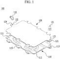
- FIG. 1 is a schematic view schematically showing a structure of a conventional cooling member for a battery module
- FIG. 2 is a plan view schematically showing a structure of the base plate of FIG. 1 .
- a cooling member 100 includes a base plate 110 and a cover plate 120.
- a receiving part 111 having a structure recessed in a direction from one side to the other side opposite thereto is formed, and a refrigerant inflow part 113 and a refrigerant outflow part 114 are formed on opposite side edges facing each other to communicate with the receiving part 111.
- a mounting part 115 for the mounting and fixing of the cooling member 100 is formed at both side edges of the base plate 110 but not at the edges where the refrigerant inflow part 113 and the refrigerant outflow part 114 are formed.
- the cover plate 120 is a structure covering the receiving part 111 of the base plate 110, and is formed of a structure having a size and shape corresponding to those of the receiving part 111 except for the mounting part 115 of the base plate 110 in a plan view.
- parts 121 and 122 corresponding to the refrigerant inflow part 113 and the refrigerant outflow part 114 of the base plate 110 are formed of a structure that is protruded in an outside direction, and a refrigerant inlet 123 and a refrigerant outlet 124 are respectively punched therethrough.
- a refrigerant inflow connection port 131 and a refrigerant outflow connection port 132 for connection with a refrigerant conduit are respectively coupled to the refrigerant inlet 123 and the refrigerant outlet 124.
- a plurality of beads 112 are protruded in the direction of one surface in which the cover plate 120 is disposed so that the refrigerant flow path from the refrigerant inflow part 113 to the refrigerant outflow part 114 may be formed in an 'S' shape.
- the refrigerant flow path formed by the beads 112 has a curved structure, a difference in the speed and flow rate of the refrigerant occurs depending on each position of the refrigerant in the flow process of the refrigerant.
- the refrigerant may not pass through the part where the bead 112 is protruded, the cooling effect in the battery module corresponding to the part where the bead 112 is formed is inevitably lowered compared with the remaining part.
- this bead 112 has a predetermined width 143 by itself, so it must be inevitably formed in a wider spacing in order to ensure sufficient refrigerant flow path widths 141 and 142 within the receiving part 111 space of the limited base plate 110.
- the cooling member 100 when the cooling member 100 is disposed facing the bottom of the battery module, since it may not be possible to exhibit sufficient structural rigidity to withstand the weight of the battery module, the formation of the refrigerant flow path in order to exhibit an efficient cooling effect is limited.
- a cooling member for a battery module with simultaneously improved cooling performance and structural rigidity and a battery pack including the same are provided.
- a cooling member for a battery module includes: a cooling plate including an upper plate and a lower plate; and a supporter disposed between the upper plate and the lower plate and having a plurality of refrigerant flow paths, wherein the lower plate has a refrigerant inflow part and a refrigerant outflow part, and a reinforcing member is formed adjacent to at least one of the refrigerant inflow part and the refrigerant outflow part.
- a receiving part of a structure that is recessed in a second surface direction disposed at a side opposite to a first surface facing the upper plate may be formed in the lower plate, and the supporter may be mounted to the receiving part.
- the reinforcing member may be formed at a part where the lower plate is not covered by the supporter.
- the reinforcing member may be formed adjacent to the refrigerant inflow part, and an entire shape of the reinforcing member may have a pattern structure in which a width is widened along the direction toward the supporter from the refrigerant inflow part.
- the edge of the supporter adjacent to the refrigerant inflow part may have a straight structure, and the edge of the supporter adjacent to the refrigerant outflow part has a bent structure.
- the plurality of refrigerant flow paths may be disposed to be parallel to each other.
- the reinforcing member may be integrally formed with the lower plate.
- the reinforcing member may include a plurality of protruding members.
- the plurality of protruding members may be disposed along a direction gradually moving away from an imaginary line connecting the refrigerant inflow part and the refrigerant outflow part.
- An angle formed between the imaginary line and the protruded member may gradually increase along the direction away from the imaginary line.
- the reinforcing member may be integrally formed with the supporter.
- the reinforcing member may extend in the direction that the refrigerant flow path extends to be toward at least one of the refrigerant inflow part and the refrigerant outflow part, and the entire shape of the reinforcing member may have a pattern structure in which the width decreases along the direction toward the refrigerant inflow part or the refrigerant outflow part.
- the reinforcing member may extend in the direction that the refrigerant flow path extends to be toward at least one of the refrigerant inflow part and the refrigerant outflow part, and the width between the refrigerant flow paths configuring the reinforcing member may be smaller than the width between the refrigerant flow paths disposed at the center part between the refrigerant inflow part and the refrigerant outflow part.
- the supporter may have the same shape as the receiving part of the lower plate except for the refrigerant inflow part and the refrigerant outflow part in a plan view.
- the cooling member for a battery module may include a first cooling member and a second cooling member connected by a conduit, the lower plate of the first cooling member may include a first refrigerant inflow part and a first refrigerant outflow part, the lower plate of the second cooling member may include a second refrigerant inflow part and a second refrigerant outflow part, and the reinforcing member may be formed adjacent to the first refrigerant inflow part, the first refrigerant outflow part, and the second refrigerant inflow part, respectively.
- Each of the edge of the supporter of the first cooling member adjacent to the first refrigerant inflow part, the edge of the support of the first cooling member adjacent to the first refrigerant outflow part, and the edge of the support of the second cooling member adjacent to the second refrigerant inflow part may have the straight structure, and the edge of the support of the second cooling member adjacent to the second refrigerant outflow part may have the bent structure.
- a battery pack according to another exemplary embodiment of the present invention may include at least one among the above-described cooling member for battery modules.
- the cooling member for the battery module and the battery pack including the same which increases the cooling performance by adding the separate supporter having the refrigerant flow path on the cooling plate, and simultaneously increases the strength by forming the separate reinforcing member on a weak part as the supporter does not cover the cooling plate, may be realized.
- the phrase “in a plan view” means when an object portion is viewed from above, and the phrase “in a cross-sectional view” means when a cross-section taken by vertically cutting an object portion is viewed from the side.
- FIG. 3 is a schematic view showing a structure of a cooling member according to an exemplary embodiment of the present invention.
- FIG. 4 is a top plan view schematically showing a structure of which a supporter is mounted to a lower plate of FIG. 3 .
- FIG. 5 is a top plan view showing a structure of a reinforcing member of FIG. 4 .
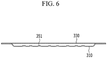
- FIG. 6 is a cross-sectional view taken along a line A-A' of FIG. 4 .
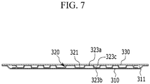
- FIG. 7 is a cross-sectional view taken along a line B-B' of FIG. 4 .
- a cooling member 300 includes a lower plate 310, a supporter 320 including a plurality of refrigerant flow path 321, and an upper plate 330.
- the cooling member 300 of the present exemplary embodiment may further include a thermal transmitting pad 340 on the upper plate 330.
- the supporter 320 according to the present exemplary embodiment may be formed by an extrusion molding method.
- the thermal transmitting pad 340 may include a silicon material or an acryl material, and the thermal transmitting pad 340 transmits heat generated from the battery module mounted on the cooling member 300 according to the present exemplary embodiment to more easily allow heat exchange through the cooling member 300.
- the lower plate 310 has a first surface facing the upper plate 330 and a second surface disposed at a side opposite to the first surface, a receiving part 311 of the structure recessed in the second surface direction is formed on the lower plate 310, and a refrigerant inflow part 312 and a refrigerant outflow part 313 of a structure communicating with the receiving part 311 are formed at both edges facing each other.
- a plurality of mounting parts 314 for mounting and fixing the cooling member 300 to the battery module and the like are formed.
- a fastening apparatus is inserted and coupled in the mounting part 314, a fastening hole 314a is formed for mounting the cooling member 300 according to the present exemplary embodiment to a device such as a battery module.
- the mounting part 314 is formed with a structure in which one side part of the mounting part 314 is recessed in the receiving part 311 direction with the fastening hole 314a as the center.
- the supporter 320 is mounted in the receiving part 311 of the lower plate 310, and the supporter 320 may have a plate-like structure in which a plurality of linear flow paths 321 are formed.
- the plurality of refrigerant flow paths 321 may be disposed parallel to each other.
- the upper plate 330 as a structure covering the receiving part 311 of the lower plate 310 may have a structure having a size and shape corresponding to those of the lower plate 310 having the receiving part 311, except for the mounting part 314 of the lower plate 310 in a plan view.
- parts 331 and 332 corresponding to the refrigerant inflow part 312 and the refrigerant outflow part 313 of the lower plate 310 may be formed of the structure protruded in the outside direction, and a refrigerant inlet 333 and a refrigerant outlet 334 having a punched structure are respectively formed on the protruded parts 331 and 332 of the refrigerant inflow part 312 and the refrigerant outflow part 313.
- the refrigerant inlet 333 and the refrigerant outlet 334 may be combined with a refrigerant inflow connection port 341 and a refrigerant outflow connection port 342, respectively, for connection to the refrigerant conduit.
- a reinforcing member 350 is formed at the part adjacent to the refrigerant inflow part 312.
- the reinforcing member 350 is formed at a portion of the lower plate 310 not covered by the supporter 320. Therefore, it is possible to prevent deformation of the cooling member 300, which may occur when the reinforcing member 350 does not cover the supporter 320.
- the reinforcing member 350 may have a pattern structure in which the width is widened in the overall shape along the direction toward the supporter 320 at the refrigerant inflow part 312.
- the reinforcing member 350 according to the present exemplary embodiment may be integrally formed with the lower plate 310, and the reinforcing member 350 may include a plurality of protruding members 351 protruded from the first surface of the lower plate 310.
- Such protruding members 351 may be a resulting material that is protruded while forming the lower plate 310 by a press method.
- the plurality of protruding members 350 may be disposed along a direction that is gradually away from an imaginary line VL connecting the refrigerant inflow part 312 and the refrigerant outflow part 313, and an angle formed between the imaginary line VL and the protruding members 350 may be gradually increased along the direction away from the imaginary line VL.
- the refrigerant inflowing to the refrigerant inflow part 312 may quickly and accurately reach the refrigerant flow path 321 formed at the supporter 320 by the arrangement structure of the protruding members 350.
- the height and area of the plurality of protruding members 350 may be used as a means to control a refrigerant flow rate, and the flow rate may be adjusted according to required conditions by functionally controlling the height and the area.
- an edge 320a of the supporter 320 adjacent to the refrigerant inflow part 312 has a straight structure
- an edge 320b of the supporter 320 adjacent to the refrigerant outflow part 313 may have a bent structure.
- the edge 320a of the supporter 320 adjacent to the refrigerant inflow part 312 is separated from the edge of the lower plate 310 in which the refrigerant inflow part 312 is formed by the region occupied by the plurality of reinforcing members 350.
- the edge 320a of the supporter 320 adjacent to the refrigerant inflow part 312 may have the substantially straight structure.
- the edge 320b of the supporter 320 adjacent to the refrigerant outflow part 313 may have the bent structure.
- the reinforcing member 350 since the reinforcing member 350 has the structure that is formed only at the position adjacent to the refrigerant inflow part 312 and is not formed at the position adjacent to the refrigerant outflow part 313, in consideration of the structural rigidity of the cooling member 300, it is preferable that the supporter 320 portion adjacent to the refrigerant outflow portion 313 is formed close to the edge of the lower plate 310.
- the edge of the lower plate 310 corresponds to the edge of the portion where the refrigerant outflow part 313 is disposed.
- the edge 320b of the supporter 320 adjacent to the refrigerant outflow part 313 is formed of the bent structure
- the region between the lower plate 310 in which the refrigerant outflow part 313 is formed and the edge 320b of the supporter 320 adjacent to the refrigerant outflow part 313 may be formed to be narrower than the region between the edge of the lower plate 310 in which the refrigerant inflow part 312 is formed and the edge 320b of the supporter 320 adjacent to the refrigerant inflow part 312.
- the bent portion depending on the bent structure may be formed at the center part of the edge 320b of the supporter 320 adjacent to the refrigerant outflow part 313.
- the reinforcing member may be additionally formed at the lower plate 310 adjacent to the refrigerant outflow part 313 as a variation example.
- the edge of the supporter 320 adjacent to the refrigerant outflow part 313 may be formed of the straight structure.
- the plurality of protruding members 351 are protruded toward the upper plate 330 from the upper surface of the lower plate 310.
- the plurality of protruding members 351 may be formed together when forming the lower plate 310 by the press method, and the plurality of protruding members 351 may be one body structure with the lower plate 310.
- the supporter 320 may form a plurality of refrigerant flow paths 321 by a protrusion and depression structure by repeating a structure of a shape of which a convex part 323a is in contact with the upper plate 330 and a concave part 323b is in contact with the lower plate 310 on a vertical cross-section.
- connection part 323c connecting the convex part 323a and the concave part 323b forms the plurality of refrigerant flow paths 321, and simultaneously supports the receiving part 311 space between the upper plate 330 and the lower plate 310. Accordingly, the structural stability may be improved by reinforcing the rigidity of the cooling member 300.
- FIG. 8 is a top plan view showing a cooling member for a battery module according to an exemplary embodiment of the present invention.
- FIG. 8 shows an example representing a structure in which an additional cooling member is further connected to the cooling member of FIG. 3 .
- a first refrigerant outflow part 513 as the refrigerant outflow part of a first cooling member 500 and the second refrigerant inflow part 312 as the refrigerant inflow part of the second cooling member 300 are connected to each other by a conduit 501 through which the refrigerant may communicate.
- the refrigerant may inflow and outflow from the first cooling member 500 to the second cooling member 300, and the cooling member of FIG. 3 may configure the second cooling member 300.
- the refrigerant inflows to a first refrigerant inflow part 512 that is the refrigerant inflow part of the first cooling member 500
- a first supporter 520 of the first cooling member 500 is formed of a structure having four edges 524a, 524b, 524c, and 524d in a plan view, and the refrigerant flow paths 521 are formed in parallel to the second edge 524b direction disposed adjacent to the first refrigerant outflow part 513 from the first edge 524a disposed adjacent to the refrigerant inflow part 512.
- the second edge 524b disposed adjacent to the first refrigerant outflow part 513 may include the bent part, and the bent part may be formed at the center part of the second edge 524b. The bent part allows the refrigerant passing through the first cooling member 500 to smoothly move to the second cooling member 300, thereby shortening the refrigerant time.
- the second supporter 320 of the second cooling member 300 is formed of the structure having four edges 324a, 324b, 324c, and 324d, and the refrigerant flow paths 321 are formed in parallel to the second edge 324b direction adjacent to the refrigerant outflow part 313 from the first edge 324a disposed adjacent to the refrigerant inflow part 312.
- the first refrigerant inflow part 512 that is the refrigerant inflow part of the first cooling member 500 may be disposed at the center part on the edge of a corresponding lower plate 510, and the first refrigerant outflow part 513 may be disposed at the center part on the edge of the corresponding lower plate 510.
- the position of the first refrigerant outflow part 513 is not limited thereto, and may be biased in the third edge 524c direction or the fourth edge 524d direction of the supporter 520.
- the first edge 524a and the second edge 524b of the first supporter 520 are spaced apart from the first refrigerant inflow part 512 and the first refrigerant outflow part 513 by a predetermined interval so as to induce the smooth inflow and outflow of the refrigerant.
- the first edge 524a of the first supporter 520 adjacent to the first refrigerant inflow part 512 has the straight structure
- the second edge 524b of the first supporter 520 adjacent to the first refrigerant outflow part 513 may have the bent structure.
- the reinforcing member 550 is formed between the first edge 524a of the first supporter 520 having the straight structure and the first refrigerant inflow part 512, and the part having the bent structure of the first supporter 520 without a separate reinforcing member is disposed between the second edge 524b of the first supporter 520 having the bent structure and the first refrigerant outflow part 513.
- Receiving part interior circumferences of the lower plate 510 corresponding to the first edge 524a and the second edge 524b respectively include inclination surfaces S1 and S2 recessed in the first refrigerant inflow part 512 and in the first refrigerant outflow part 513 direction so as to induce the smooth inflow and outflow of the refrigerant.
- the second refrigerant inflow part 312 that is the refrigerant inflow part of the second cooling member 300 may be disposed at the center part on the edge of the corresponding lower plate 310, and the second refrigerant outflow part 313 may be disposed at the center part on the edge of the corresponding lower plate 310.
- the position of the second refrigerant outflow part 313 is not limited thereto, and may be biased to the third edge 324c direction or the fourth edge 324d direction of the supporter 320..
- the remaining structure of the second cooling member 300 is the same as that of the first cooling member 500, so a detailed description thereof is omitted.
- FIG. 9 is a top plan view showing a modified example of the cooling member of FIG. 8 .
- FIG. 9 an example to be described in FIG. 9 is the same as most of the example described in FIG. 8 , however there is a difference that a reinforcing member 550 is additionally formed between the second edge 524b of the first supporter 520 and the refrigerant outflow part 513. Also, the second edge 524b of the first supporter 520 adjacent to the refrigerant outflow part 513 may have the straight structure, not the bent structure.
- a reinforcing member 550 may be additionally formed between the second edge 524b of the first supporter 520 and the refrigerant outflow part 513 to adjust the path and the flow speed of the refrigerant.
- the cooling efficiency may be further improved.
- FIG. 10 is a schematic view showing a structure of a cooling member according to an exemplary embodiment of the present invention.
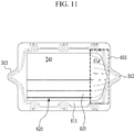
- FIG. 11 is a top plan view schematically showing a structure in which a supporter is mounted to a lower plate of FIG. 10 .
- FIG. 10 and FIG. 11 An example to be described in FIG. 10 and FIG. 11 is the same as most of the example described with reference to FIG. 3 and FIG. 4 , however there are differences in a method of forming the reinforcing member and the structure of the reinforcing member manufactured according thereto, and are mainly described.
- a supporter 620 is mounted on a receiving part 611 of a lower plate 610, and the supporter 620 includes a plurality of refrigerant flow paths 621.
- the supporter 620 may include a first region adjacent to the refrigerant inflow part 312, a second region adjacent to the refrigerant outflow part 313, and a third region disposed between the first region and the second region. In the second region and the third region, the plurality of refrigerant flow paths 621 may be disposed to be parallel to each other and have the straight structure.
- the plurality of refrigerant flow paths 621 may be bent toward the part where the plurality of refrigerant flow paths 621 of the second region extend and the refrigerant inflow part 312 is disposed.
- a reinforcing member 650 according to the present exemplary embodiment is made of the structure extending in the direction that the plurality of refrigerant flow paths 621 disposed in the second region extend to be toward the refrigerant inflow part 312.
- the entire shape of the reinforcing member 650 may have a patterned structure of which the width is narrowed along the direction toward the refrigerant inflow part 312.
- a width d1 between the refrigerant flow paths 621 configuring the reinforcing member 650 may be smaller than a width d2 between the refrigerant flow paths 621 disposed in the second region corresponding to the center part between the refrigerant inflow part 312 and the refrigerant outflow part 313.
- the supporter 620 may have the same shape as the receiving part 611 of the lower plate 620 except for the refrigerant inflow part 312 and the refrigerant outflow part 313 in a plan view.
- the reinforcing member 650 may be integrally formed with the supporter 620.
- the pressing method may be used to integrally form the supporter 620 and the reinforcing member 650.
Landscapes
- Chemical & Material Sciences (AREA)
- Chemical Kinetics & Catalysis (AREA)
- Electrochemistry (AREA)
- General Chemical & Material Sciences (AREA)
- Engineering & Computer Science (AREA)
- Manufacturing & Machinery (AREA)
- Secondary Cells (AREA)
- Battery Mounting, Suspending (AREA)
Abstract
Description
- This application claims priority to and the benefit of Korean Patent Application No.
10-2018-0058368 - The present invention relates to a cooling member for a battery module and a battery pack including the same.
- Rechargeable batteries are attracting attention as a power source for electric vehicles (EV), hybrid electric vehicles (HEV), plug-in hybrid electric vehicles (PHEV), etc. that are presented as a solution to solve air pollution and the like of conventional gasoline vehicles and diesel vehicles using fossil fuels.
- While small mobile devices use one or more battery cells per device, medium and large devices such as automobiles use a medium or large battery module in which a plurality of battery cells are electrically connected due to the necessity of high power/capacity.
- Since it is preferable for the medium and large battery module to be manufactured with as small a size and weight as possible, a prismatic battery and a pouch type battery, which may have a high integration degree and have a small weight with respect to capacity, are mainly used as a battery cell of the medium and large battery module. Particularly, a pouch-shaped battery using an aluminum laminate sheet or the like as an exterior member has recently attracted a great deal of attention due to its small weight, low manufacturing cost, and ease of shape deformation.
- The battery cells constituting the medium and large battery module are composed of a rechargeable battery, and such a high power/capacity rechargeable battery generates a large amount of heat during charge and discharge processes. Particularly, a laminate sheet of the pouch-type battery widely used in a battery module is coated with a polymer material with low thermal conductivity at the surface, so it is difficult to effectively cool the entire battery cell.
- If the heat from the battery module generated during the charge and discharge process is not effectively removed, heat accumulation occurs and resultantly the deterioration of the battery module is accelerated, and in some cases, ignition or explosion may be caused. Therefore, in the medium or large battery pack for the vehicle, which contains a large number of medium and large battery modules and is the high power/capacity battery, or the medium or large battery pack for an electric power storage device, a cooling system for cooling the battery cells built therein is required.
- Therefore, the battery module mounted on the medium and large battery pack is generally manufactured by a method of stacking a plurality of battery cells at a high density and is formed of a structure in which the battery cells are stacked to be separated by a predetermined interval to remove the heat generated during the charge and discharge. For example, to configure the battery module, the battery cells themselves may be stacked sequentially at a predetermined interval without a separate member, or in the case of a battery cell having low mechanical rigidity, one or more combinations of the battery cells may be assembled into a cartridge to form a unit module and a plurality of unit modules may be stacked. If the cartridge is used when configuring the battery module, there is a merit that the mechanical rigidity increases, but there is also a drawback that the overall size of the battery module increases.
- Also, a flow path for a refrigerant is formed between the battery cells or the battery modules so as to effectively remove the accumulated heat between the stacked battery cells or the battery modules. However, this structure has a problem in that the entire size of the battery module becomes large because a plurality of the refrigerant flow paths corresponding to a plurality of battery cells must be secured.
- Also, by considering the size of the battery module, refrigerant flow paths with a relatively narrow interval are formed as many battery cells are stacked, thereby there is a problem that a design of a cooling structure becomes complicated. In other words, refrigerant flow paths with a relatively narrow interval with respect to an inlet of the refrigerant causes high pressure loss, which makes it difficult to design the shape and position of the inlet and outlet of the refrigerant.
- Thus, in the case where the cooling structure is a water-cooled cooling system, in a more advanced manner, in a state that the cooling member having a structure including the refrigerant flow path inside faces and contacts the battery module, a method of passing the refrigerant through the refrigerant flow path in the cooling member for heat exchanging is mainly used.
-
FIG. 1 is a schematic view schematically showing a structure of a conventional cooling member for a battery module, andFIG. 2 is a plan view schematically showing a structure of the base plate ofFIG. 1 . - Referring to
FIG. 1 andFIG. 2 , acooling member 100 includes abase plate 110 and acover plate 120. In thebase plate 110, areceiving part 111 having a structure recessed in a direction from one side to the other side opposite thereto is formed, and arefrigerant inflow part 113 and arefrigerant outflow part 114 are formed on opposite side edges facing each other to communicate with thereceiving part 111. - A mounting
part 115 for the mounting and fixing of thecooling member 100 is formed at both side edges of thebase plate 110 but not at the edges where the refrigerant inflowpart 113 and therefrigerant outflow part 114 are formed. - The
cover plate 120 is a structure covering thereceiving part 111 of thebase plate 110, and is formed of a structure having a size and shape corresponding to those of thereceiving part 111 except for themounting part 115 of thebase plate 110 in a plan view. - Among the edges of the
cover plate 120,parts refrigerant inflow part 113 and therefrigerant outflow part 114 of thebase plate 110 are formed of a structure that is protruded in an outside direction, and arefrigerant inlet 123 and arefrigerant outlet 124 are respectively punched therethrough. - A refrigerant
inflow connection port 131 and a refrigerantoutflow connection port 132 for connection with a refrigerant conduit are respectively coupled to therefrigerant inlet 123 and therefrigerant outlet 124. - In the
receiving part 111 of thebase plate 110, a plurality ofbeads 112 are protruded in the direction of one surface in which thecover plate 120 is disposed so that the refrigerant flow path from therefrigerant inflow part 113 to therefrigerant outflow part 114 may be formed in an 'S' shape. - However, since the refrigerant flow path formed by the
beads 112 has a curved structure, a difference in the speed and flow rate of the refrigerant occurs depending on each position of the refrigerant in the flow process of the refrigerant. In particular, since the refrigerant may not pass through the part where thebead 112 is protruded, the cooling effect in the battery module corresponding to the part where thebead 112 is formed is inevitably lowered compared with the remaining part. - Accordingly, in the battery module to which the
cooling member 100 is applied, there is a difference in local cooling effect, so that uniform cooling of the battery module using thecooling member 100 is difficult. Moreover, thisbead 112 has apredetermined width 143 by itself, so it must be inevitably formed in a wider spacing in order to ensure sufficient refrigerantflow path widths receiving part 111 space of thelimited base plate 110. - Thus, when the
cooling member 100 is disposed facing the bottom of the battery module, since it may not be possible to exhibit sufficient structural rigidity to withstand the weight of the battery module, the formation of the refrigerant flow path in order to exhibit an efficient cooling effect is limited. - Therefore, there is a high necessity for a technique that may fundamentally solve such a problem.
- According to an exemplary embodiment of the present invention, a cooling member for a battery module with simultaneously improved cooling performance and structural rigidity and a battery pack including the same are provided.
- However, objects to be solved by the embodiments of the present disclosure are not limited to the above-mentioned problems, and can be variously extended within the scope of the technical idea included in the present invention.
- A cooling member for a battery module according to an exemplary embodiment of the present invention includes: a cooling plate including an upper plate and a lower plate; and a supporter disposed between the upper plate and the lower plate and having a plurality of refrigerant flow paths, wherein the lower plate has a refrigerant inflow part and a refrigerant outflow part, and a reinforcing member is formed adjacent to at least one of the refrigerant inflow part and the refrigerant outflow part.
- A receiving part of a structure that is recessed in a second surface direction disposed at a side opposite to a first surface facing the upper plate may be formed in the lower plate, and the supporter may be mounted to the receiving part.
- The reinforcing member may be formed at a part where the lower plate is not covered by the supporter.
- The reinforcing member may be formed adjacent to the refrigerant inflow part, and an entire shape of the reinforcing member may have a pattern structure in which a width is widened along the direction toward the supporter from the refrigerant inflow part.
- The edge of the supporter adjacent to the refrigerant inflow part may have a straight structure, and the edge of the supporter adjacent to the refrigerant outflow part has a bent structure.
- The plurality of refrigerant flow paths may be disposed to be parallel to each other.
- The reinforcing member may be integrally formed with the lower plate.
- The reinforcing member may include a plurality of protruding members.
- The plurality of protruding members may be disposed along a direction gradually moving away from an imaginary line connecting the refrigerant inflow part and the refrigerant outflow part.
- An angle formed between the imaginary line and the protruded member may gradually increase along the direction away from the imaginary line.
- The reinforcing member may be integrally formed with the supporter.
- The reinforcing member may extend in the direction that the refrigerant flow path extends to be toward at least one of the refrigerant inflow part and the refrigerant outflow part, and the entire shape of the reinforcing member may have a pattern structure in which the width decreases along the direction toward the refrigerant inflow part or the refrigerant outflow part.
- The reinforcing member may extend in the direction that the refrigerant flow path extends to be toward at least one of the refrigerant inflow part and the refrigerant outflow part, and the width between the refrigerant flow paths configuring the reinforcing member may be smaller than the width between the refrigerant flow paths disposed at the center part between the refrigerant inflow part and the refrigerant outflow part.
- The supporter may have the same shape as the receiving part of the lower plate except for the refrigerant inflow part and the refrigerant outflow part in a plan view.
- The cooling member for a battery module may include a first cooling member and a second cooling member connected by a conduit, the lower plate of the first cooling member may include a first refrigerant inflow part and a first refrigerant outflow part, the lower plate of the second cooling member may include a second refrigerant inflow part and a second refrigerant outflow part, and the reinforcing member may be formed adjacent to the first refrigerant inflow part, the first refrigerant outflow part, and the second refrigerant inflow part, respectively.
- Each of the edge of the supporter of the first cooling member adjacent to the first refrigerant inflow part, the edge of the support of the first cooling member adjacent to the first refrigerant outflow part, and the edge of the support of the second cooling member adjacent to the second refrigerant inflow part may have the straight structure, and the edge of the support of the second cooling member adjacent to the second refrigerant outflow part may have the bent structure.
- A battery pack according to another exemplary embodiment of the present invention may include at least one among the above-described cooling member for battery modules.
- According to the exemplary embodiments, the cooling member for the battery module and the battery pack including the same, which increases the cooling performance by adding the separate supporter having the refrigerant flow path on the cooling plate, and simultaneously increases the strength by forming the separate reinforcing member on a weak part as the supporter does not cover the cooling plate, may be realized.
-
-
FIG. 1 is a schematic view schematically showing a structure of a conventional cooling member for a battery module. -
FIG. 2 is a plan view schematically showing a structure of the base plate ofFIG. 1 . -
FIG. 3 is a schematic view showing a structure of a cooling member according to an exemplary embodiment of the present invention. -
FIG. 4 is a top plan view schematically showing a structure of which a supporter is mounted to a lower plate ofFIG. 3 . -
FIG. 5 is a top plan view showing a structure of a reinforcing member ofFIG. 4 . -
FIG. 6 is a cross-sectional view taken along a line A-A' ofFIG. 4 . -
FIG. 7 is a cross-sectional view taken along a line B-B' ofFIG. 4 . -
FIG. 8 is a top plan view showing a cooling member for a battery module according to an exemplary embodiment of the present invention. -
FIG. 9 is a top plan view showing a variation example of the cooling member ofFIG. 8 . -
FIG. 10 is a schematic view showing a structure of a cooling member according to an exemplary embodiment of the present invention. -
FIG. 11 is a top plan view schematically showing a structure of which a supporter is mounted to a lower plate ofFIG. 10 . - The present invention will be described more fully hereinafter with reference to the accompanying drawings, in which exemplary embodiments of the invention are shown. As those skilled in the art would realize, the described embodiments may be modified in various different ways, all without departing from the spirit or scope of the present invention.
- Further, in the drawings, a size and thickness of each element are arbitrarily represented for better understanding and ease of description, and the present invention is not limited thereto. In the drawings, the thickness of layers, films, panels, regions, etc., are exaggerated for clarity. In the drawings, for better understanding and ease of description, the thicknesses of some layers and areas are exaggerated.
- It will be understood that when an element such as a layer, film, region, or substrate is referred to as being "on" another element, it can be directly on the other element or intervening elements may also be present. In contrast, when an element is referred to as being "directly on" another element, there are no intervening elements present. Further, in the specification, the word "on" or "above" means positioned on or below the object portion, and does not necessarily mean positioned on the upper side of the object portion based on a gravitational direction.
- In addition, unless explicitly described to the contrary, the word "comprise" and variations such as "comprises" or "comprising" will be understood to imply the inclusion of stated elements but not the exclusion of any other elements.
- Further, in the specification, the phrase "in a plan view" means when an object portion is viewed from above, and the phrase "in a cross-sectional view" means when a cross-section taken by vertically cutting an object portion is viewed from the side.
-
FIG. 3 is a schematic view showing a structure of a cooling member according to an exemplary embodiment of the present invention.FIG. 4 is a top plan view schematically showing a structure of which a supporter is mounted to a lower plate ofFIG. 3 .FIG. 5 is a top plan view showing a structure of a reinforcing member ofFIG. 4 .FIG. 6 is a cross-sectional view taken along a line A-A' ofFIG. 4 .FIG. 7 is a cross-sectional view taken along a line B-B' ofFIG. 4 . - Referring to
FIG. 3 , a coolingmember 300 according to an exemplary embodiment of the present invention includes alower plate 310, asupporter 320 including a plurality ofrefrigerant flow path 321, and anupper plate 330. The coolingmember 300 of the present exemplary embodiment may further include athermal transmitting pad 340 on theupper plate 330. Thesupporter 320 according to the present exemplary embodiment may be formed by an extrusion molding method. - The
thermal transmitting pad 340 may include a silicon material or an acryl material, and thethermal transmitting pad 340 transmits heat generated from the battery module mounted on the coolingmember 300 according to the present exemplary embodiment to more easily allow heat exchange through the coolingmember 300. - Referring to
FIG. 3 andFIG. 4 , thelower plate 310 has a first surface facing theupper plate 330 and a second surface disposed at a side opposite to the first surface, a receivingpart 311 of the structure recessed in the second surface direction is formed on thelower plate 310, and arefrigerant inflow part 312 and arefrigerant outflow part 313 of a structure communicating with the receivingpart 311 are formed at both edges facing each other. - At both edges of the
lower plate 310 excluding the edges on which therefrigerant inflow part 312 and therefrigerant outflow part 313 are formed, a plurality of mountingparts 314 for mounting and fixing the coolingmember 300 to the battery module and the like are formed. As a fastening apparatus is inserted and coupled in the mountingpart 314, afastening hole 314a is formed for mounting the coolingmember 300 according to the present exemplary embodiment to a device such as a battery module. - The mounting
part 314 is formed with a structure in which one side part of the mountingpart 314 is recessed in the receivingpart 311 direction with thefastening hole 314a as the center. As shown inFIG. 4 , thesupporter 320 is mounted in the receivingpart 311 of thelower plate 310, and thesupporter 320 may have a plate-like structure in which a plurality oflinear flow paths 321 are formed. The plurality ofrefrigerant flow paths 321 may be disposed parallel to each other. - The
upper plate 330 as a structure covering the receivingpart 311 of thelower plate 310 may have a structure having a size and shape corresponding to those of thelower plate 310 having the receivingpart 311, except for the mountingpart 314 of thelower plate 310 in a plan view. - Among the edges of the
upper plate 330,parts refrigerant inflow part 312 and therefrigerant outflow part 313 of thelower plate 310 may be formed of the structure protruded in the outside direction, and arefrigerant inlet 333 and a refrigerant outlet 334 having a punched structure are respectively formed on the protrudedparts refrigerant inflow part 312 and therefrigerant outflow part 313. - The
refrigerant inlet 333 and the refrigerant outlet 334 may be combined with a refrigerantinflow connection port 341 and a refrigerantoutflow connection port 342, respectively, for connection to the refrigerant conduit. - In the
lower plate 310 of the coolingmember 300 according to the present exemplary embodiment, a reinforcingmember 350 is formed at the part adjacent to therefrigerant inflow part 312. The reinforcingmember 350 is formed at a portion of thelower plate 310 not covered by thesupporter 320. Therefore, it is possible to prevent deformation of the coolingmember 300, which may occur when the reinforcingmember 350 does not cover thesupporter 320. - Referring to
FIG. 5 , the reinforcingmember 350 according to the present exemplary embodiment may have a pattern structure in which the width is widened in the overall shape along the direction toward thesupporter 320 at therefrigerant inflow part 312. The reinforcingmember 350 according to the present exemplary embodiment may be integrally formed with thelower plate 310, and the reinforcingmember 350 may include a plurality of protrudingmembers 351 protruded from the first surface of thelower plate 310. Such protrudingmembers 351 may be a resulting material that is protruded while forming thelower plate 310 by a press method. - The plurality of protruding
members 350 may be disposed along a direction that is gradually away from an imaginary line VL connecting therefrigerant inflow part 312 and therefrigerant outflow part 313, and an angle formed between the imaginary line VL and the protrudingmembers 350 may be gradually increased along the direction away from the imaginary line VL. The refrigerant inflowing to therefrigerant inflow part 312 may quickly and accurately reach therefrigerant flow path 321 formed at thesupporter 320 by the arrangement structure of the protrudingmembers 350. - The height and area of the plurality of protruding
members 350 may be used as a means to control a refrigerant flow rate, and the flow rate may be adjusted according to required conditions by functionally controlling the height and the area. - Again referring to
FIG. 4 , anedge 320a of thesupporter 320 adjacent to therefrigerant inflow part 312 has a straight structure, and anedge 320b of thesupporter 320 adjacent to therefrigerant outflow part 313 may have a bent structure. In an example shown inFIG. 4 , to ensure the space to form the reinforcingmember 350 between therefrigerant inflow part 312 and thesupporter 320, theedge 320a of thesupporter 320 adjacent to therefrigerant inflow part 312 is separated from the edge of thelower plate 310 in which therefrigerant inflow part 312 is formed by the region occupied by the plurality of reinforcingmembers 350. - Also, referring to
FIG. 5 , to have the pattern structure of the reinforcingmember 350 as described above, theedge 320a of thesupporter 320 adjacent to therefrigerant inflow part 312 may have the substantially straight structure. Alternatively, theedge 320b of thesupporter 320 adjacent to therefrigerant outflow part 313 may have the bent structure. In the present exemplary embodiment, since the reinforcingmember 350 has the structure that is formed only at the position adjacent to therefrigerant inflow part 312 and is not formed at the position adjacent to therefrigerant outflow part 313, in consideration of the structural rigidity of the coolingmember 300, it is preferable that thesupporter 320 portion adjacent to therefrigerant outflow portion 313 is formed close to the edge of thelower plate 310. Here, the edge of thelower plate 310 corresponds to the edge of the portion where therefrigerant outflow part 313 is disposed. - Accordingly, in the present exemplary embodiment, as the
edge 320b of thesupporter 320 adjacent to therefrigerant outflow part 313 is formed of the bent structure, the region between thelower plate 310 in which therefrigerant outflow part 313 is formed and theedge 320b of thesupporter 320 adjacent to therefrigerant outflow part 313 may be formed to be narrower than the region between the edge of thelower plate 310 in which therefrigerant inflow part 312 is formed and theedge 320b of thesupporter 320 adjacent to therefrigerant inflow part 312. The bent portion depending on the bent structure may be formed at the center part of theedge 320b of thesupporter 320 adjacent to therefrigerant outflow part 313. - In the above example, it is described that only one reinforcing member is formed in one lower plate, however it is possible for the reinforcing member to be additionally formed at the
lower plate 310 adjacent to therefrigerant outflow part 313 as a variation example. In this case, the edge of thesupporter 320 adjacent to therefrigerant outflow part 313 may be formed of the straight structure. - Referring to
FIG. 6 , the plurality of protrudingmembers 351 are protruded toward theupper plate 330 from the upper surface of thelower plate 310. As described above, the plurality of protrudingmembers 351 may be formed together when forming thelower plate 310 by the press method, and the plurality of protrudingmembers 351 may be one body structure with thelower plate 310. - Referring to
FIG. 7 , thesupporter 320 may form a plurality ofrefrigerant flow paths 321 by a protrusion and depression structure by repeating a structure of a shape of which aconvex part 323a is in contact with theupper plate 330 and aconcave part 323b is in contact with thelower plate 310 on a vertical cross-section. - Accordingly, a
connection part 323c connecting theconvex part 323a and theconcave part 323b forms the plurality ofrefrigerant flow paths 321, and simultaneously supports the receivingpart 311 space between theupper plate 330 and thelower plate 310. Accordingly, the structural stability may be improved by reinforcing the rigidity of the coolingmember 300. -
FIG. 8 is a top plan view showing a cooling member for a battery module according to an exemplary embodiment of the present invention.FIG. 8 shows an example representing a structure in which an additional cooling member is further connected to the cooling member ofFIG. 3 . - Referring to
FIG. 8 , a firstrefrigerant outflow part 513 as the refrigerant outflow part of afirst cooling member 500 and the secondrefrigerant inflow part 312 as the refrigerant inflow part of thesecond cooling member 300 are connected to each other by aconduit 501 through which the refrigerant may communicate. - The refrigerant may inflow and outflow from the
first cooling member 500 to thesecond cooling member 300, and the cooling member ofFIG. 3 may configure thesecond cooling member 300. Specifically, the refrigerant inflows to a firstrefrigerant inflow part 512 that is the refrigerant inflow part of thefirst cooling member 500, the refrigerant outflows to the firstrefrigerant outflow part 513 that is the refrigerant outflow part of thefirst cooling member 500 after passing through a firstrefrigerant flow path 521, the refrigerant inflows to the secondrefrigerant inflow part 312 that is the refrigerant inflow part of thesecond cooling member 300 through theconduit 501, and the refrigerant outflows to the secondrefrigerant outflow part 313 that is the refrigerant outflow part of thesecond cooling member 300 after passing through the secondrefrigerant flow path 321. - A
first supporter 520 of thefirst cooling member 500 is formed of a structure having fouredges refrigerant flow paths 521 are formed in parallel to thesecond edge 524b direction disposed adjacent to the firstrefrigerant outflow part 513 from thefirst edge 524a disposed adjacent to therefrigerant inflow part 512. Here, thesecond edge 524b disposed adjacent to the firstrefrigerant outflow part 513 may include the bent part, and the bent part may be formed at the center part of thesecond edge 524b. The bent part allows the refrigerant passing through thefirst cooling member 500 to smoothly move to thesecond cooling member 300, thereby shortening the refrigerant time. - Similarly, the
second supporter 320 of thesecond cooling member 300 is formed of the structure having fouredges refrigerant flow paths 321 are formed in parallel to thesecond edge 324b direction adjacent to therefrigerant outflow part 313 from thefirst edge 324a disposed adjacent to therefrigerant inflow part 312. - The first
refrigerant inflow part 512 that is the refrigerant inflow part of thefirst cooling member 500 may be disposed at the center part on the edge of a correspondinglower plate 510, and the firstrefrigerant outflow part 513 may be disposed at the center part on the edge of the correspondinglower plate 510. The position of the firstrefrigerant outflow part 513 is not limited thereto, and may be biased in thethird edge 524c direction or thefourth edge 524d direction of thesupporter 520. - The
first edge 524a and thesecond edge 524b of thefirst supporter 520 are spaced apart from the firstrefrigerant inflow part 512 and the firstrefrigerant outflow part 513 by a predetermined interval so as to induce the smooth inflow and outflow of the refrigerant. However, thefirst edge 524a of thefirst supporter 520 adjacent to the firstrefrigerant inflow part 512 has the straight structure, and thesecond edge 524b of thefirst supporter 520 adjacent to the firstrefrigerant outflow part 513 may have the bent structure. The reinforcingmember 550 is formed between thefirst edge 524a of thefirst supporter 520 having the straight structure and the firstrefrigerant inflow part 512, and the part having the bent structure of thefirst supporter 520 without a separate reinforcing member is disposed between thesecond edge 524b of thefirst supporter 520 having the bent structure and the firstrefrigerant outflow part 513. - Receiving part interior circumferences of the
lower plate 510 corresponding to thefirst edge 524a and thesecond edge 524b respectively include inclination surfaces S1 and S2 recessed in the firstrefrigerant inflow part 512 and in the firstrefrigerant outflow part 513 direction so as to induce the smooth inflow and outflow of the refrigerant. - The second
refrigerant inflow part 312 that is the refrigerant inflow part of thesecond cooling member 300 may be disposed at the center part on the edge of the correspondinglower plate 310, and the secondrefrigerant outflow part 313 may be disposed at the center part on the edge of the correspondinglower plate 310. The position of the secondrefrigerant outflow part 313 is not limited thereto, and may be biased to thethird edge 324c direction or thefourth edge 324d direction of thesupporter 320.. - The remaining structure of the
second cooling member 300 is the same as that of thefirst cooling member 500, so a detailed description thereof is omitted. -
FIG. 9 is a top plan view showing a modified example of the cooling member ofFIG. 8 . - Referring to
FIG. 9 , an example to be described inFIG. 9 is the same as most of the example described inFIG. 8 , however there is a difference that a reinforcingmember 550 is additionally formed between thesecond edge 524b of thefirst supporter 520 and therefrigerant outflow part 513. Also, thesecond edge 524b of thefirst supporter 520 adjacent to therefrigerant outflow part 513 may have the straight structure, not the bent structure. In the cooling member according to the present exemplary embodiment, in the case that the plurality of cooling members are connected, when considering a point that the refrigerant discharged through therefrigerant outflow part 513 of thefirst cooling member 500 again enters thesecond cooling member 300 for performing the cooling action, a reinforcingmember 550 may be additionally formed between thesecond edge 524b of thefirst supporter 520 and therefrigerant outflow part 513 to adjust the path and the flow speed of the refrigerant. Thus, the cooling efficiency may be further improved. - In addition to the differences described above, the contents described with reference to
FIG. 8 may all be applied to the present exemplary embodiment. -
FIG. 10 is a schematic view showing a structure of a cooling member according to an exemplary embodiment of the present invention.FIG. 11 is a top plan view schematically showing a structure in which a supporter is mounted to a lower plate ofFIG. 10 . - An example to be described in
FIG. 10 andFIG. 11 is the same as most of the example described with reference toFIG. 3 andFIG. 4 , however there are differences in a method of forming the reinforcing member and the structure of the reinforcing member manufactured according thereto, and are mainly described. - Referring to
FIG. 10 andFIG. 11 , in a coolingmember 600 according to the present exemplary embodiment, asupporter 620 is mounted on a receivingpart 611 of alower plate 610, and thesupporter 620 includes a plurality ofrefrigerant flow paths 621. Thesupporter 620 according to the present exemplary embodiment may include a first region adjacent to therefrigerant inflow part 312, a second region adjacent to therefrigerant outflow part 313, and a third region disposed between the first region and the second region. In the second region and the third region, the plurality ofrefrigerant flow paths 621 may be disposed to be parallel to each other and have the straight structure. In the first region, the plurality ofrefrigerant flow paths 621 may be bent toward the part where the plurality ofrefrigerant flow paths 621 of the second region extend and therefrigerant inflow part 312 is disposed. In detail, a reinforcingmember 650 according to the present exemplary embodiment is made of the structure extending in the direction that the plurality ofrefrigerant flow paths 621 disposed in the second region extend to be toward therefrigerant inflow part 312. The entire shape of the reinforcingmember 650 may have a patterned structure of which the width is narrowed along the direction toward therefrigerant inflow part 312. In this case, a width d1 between therefrigerant flow paths 621 configuring the reinforcingmember 650 may be smaller than a width d2 between therefrigerant flow paths 621 disposed in the second region corresponding to the center part between therefrigerant inflow part 312 and therefrigerant outflow part 313. - The
supporter 620 according to the present exemplary embodiment may have the same shape as the receivingpart 611 of thelower plate 620 except for therefrigerant inflow part 312 and therefrigerant outflow part 313 in a plan view. - In the present exemplary embodiment, the reinforcing
member 650 may be integrally formed with thesupporter 620. The pressing method may be used to integrally form thesupporter 620 and the reinforcingmember 650. - While this invention has been described in connection with what is presently considered to be practical exemplary embodiments, it is to be understood that the invention is not limited to the disclosed embodiments. On the contrary, it is intended to cover various modifications and equivalent arrangements included within the spirit and scope of the appended claims.
-
- 300: cooling member
- 310, 510: lower plate
- 320, 520: supporter
- 321: refrigerant flow path
- 330: upper plate
- 350: reinforcing member
Claims (17)
- A cooling member for a battery module, comprising:a cooling plate including an upper plate and a lower plate; anda supporter disposed between the upper plate and the lower plate and having a plurality of refrigerant flow paths,wherein the lower plate has a refrigerant inflow part and a refrigerant outflow part, and a reinforcing member is formed adjacent to at least one of the refrigerant inflow part and the refrigerant outflow part.
- The cooling member for the battery module of claim 1, wherein
a receiving part of a structure that is recessed in a second surface direction disposed at a side opposite to a first surface facing the upper plate is formed in the lower plate, and the supporter is mounted to the receiving part. - The cooling member for the battery module of claim 1, wherein
the reinforcing member is formed at a part where the lower plate is not covered by the supporter. - The cooling member for the battery module of claim 3, wherein
the reinforcing member is formed adjacent to the refrigerant inflow part, and an entire shape of the reinforcing member has a pattern structure in which a width is widened along the direction toward the supporter from the refrigerant inflow part. - The cooling member for the battery module of claim 4, wherein
the edge of the supporter adjacent to the refrigerant inflow part has a straight structure, and the edge of the supporter adjacent to the refrigerant outflow part has a bent structure. - The cooling member for the battery module of claim 1, wherein
the plurality of refrigerant flow paths are disposed to be parallel to each other. - The cooling member for the battery module of claim 1, wherein
the reinforcing member is integrally formed with the lower plate. - The cooling member for the battery module of claim 1, wherein
the reinforcing member includes a plurality of protruded members. - The cooling member for the battery module of claim 8, wherein
the plurality of protruded members are disposed along a direction gradually moving away from an imaginary line connecting the refrigerant inflow part and the refrigerant outflow part. - The cooling member for the battery module of claim 9, wherein
an angle formed between the imaginary line and the protruded member gradually increases along the direction away from the imaginary line. - The cooling member for the battery module of claim 1, wherein
the reinforcing member is integrally formed with the supporter. - The cooling member for the battery module of claim 11, wherein
the reinforcing member extends in the direction that the refrigerant flow path extends to be toward at least one of the refrigerant inflow part and the refrigerant outflow part, and the entire shape of the reinforcing member has a pattern structure in which the width decreases along the direction toward the refrigerant inflow part or the refrigerant outflow part. - The cooling member for the battery module of claim 11, wherein
the reinforcing member extends in the direction that the refrigerant flow path extends to be toward at least one of the refrigerant inflow part and the refrigerant outflow part, and the width between the refrigerant flow paths configuring the reinforcing member is smaller than the width between the refrigerant flow paths disposed at the center part between the refrigerant inflow part and the refrigerant outflow part. - The cooling member for the battery module of claim 11, wherein
the supporter has the same shape as a receiving part of the lower plate except for the refrigerant inflow part and the refrigerant outflow part in a plan view. - The cooling member for the battery module of claim 1, wherein
the cooling member for a battery module includes a first cooling member and a second cooling member connected by a conduit,
the lower plate of the first cooling member includes a first refrigerant inflow part and a first refrigerant outflow part, the lower plate of the second cooling member includes a second refrigerant inflow part and a second refrigerant outflow part, and the reinforcing member is formed adjacent to the first refrigerant inflow part, the first refrigerant outflow part, and the second refrigerant inflow part, respectively. - The cooling member for the battery module of claim 15, wherein
each of the edge of the supporter of the first cooling member adjacent to the first refrigerant inflow part, the edge of the supporter of the first cooling member adjacent to the first refrigerant outflow part, and the edge of the supporter of the second cooling member adjacent to the second refrigerant inflow part has the straight structure, and the edge of the supporter of the second cooling member adjacent to the second refrigerant outflow part has the bent structure. - A battery pack including at least one among the cooling member for the battery modules of claim 1.
Applications Claiming Priority (2)
| Application Number | Priority Date | Filing Date | Title |
|---|---|---|---|
| KR1020180058368A KR102391984B1 (en) | 2018-05-23 | 2018-05-23 | Cooling member for battery module and battery pack including the same |
| PCT/KR2019/003118 WO2019225846A1 (en) | 2018-05-23 | 2019-03-18 | Cooling member for battery module, and battery pack comprising same |
Publications (3)
| Publication Number | Publication Date |
|---|---|
| EP3723188A1 true EP3723188A1 (en) | 2020-10-14 |
| EP3723188A4 EP3723188A4 (en) | 2021-03-24 |
| EP3723188B1 EP3723188B1 (en) | 2026-01-28 |
Family
ID=68615606
Family Applications (1)
| Application Number | Title | Priority Date | Filing Date |
|---|---|---|---|
| EP19808023.6A Active EP3723188B1 (en) | 2018-05-23 | 2019-03-18 | Cooling member for battery module and battery pack including the same |
Country Status (7)
| Country | Link |
|---|---|
| US (1) | US11799145B2 (en) |
| EP (1) | EP3723188B1 (en) |
| JP (1) | JP7062869B2 (en) |
| KR (1) | KR102391984B1 (en) |
| CN (1) | CN111630708A (en) |
| ES (1) | ES3063515T3 (en) |
| WO (1) | WO2019225846A1 (en) |
Cited By (8)
| Publication number | Priority date | Publication date | Assignee | Title |
|---|---|---|---|---|
| WO2022176350A1 (en) * | 2021-02-19 | 2022-08-25 | パナソニックIpマネジメント株式会社 | Vehicle and heat exchange plate |
| JP2022127457A (en) * | 2021-02-19 | 2022-08-31 | パナソニックIpマネジメント株式会社 | Vehicle and heat exchange plate |
| JP2022138470A (en) * | 2021-03-10 | 2022-09-26 | パナソニックIpマネジメント株式会社 | Vehicle and heat exchange plate |
| JP2022138471A (en) * | 2021-03-10 | 2022-09-26 | パナソニックIpマネジメント株式会社 | Vehicle and heat exchange plate |
| WO2023088997A1 (en) * | 2021-11-17 | 2023-05-25 | Webasto SE | Device for controlling the temperature of a vehicle battery |
| EP4254619A4 (en) * | 2021-03-18 | 2025-03-05 | LG Energy Solution, Ltd. | BATTERY MODULE AND BATTERY PACK |
| EP4546506A1 (en) * | 2023-10-25 | 2025-04-30 | Jinko Energy Storage Technology Co., Ltd. | Liquid cooling plate and battery pack |
| EP4478488A4 (en) * | 2022-02-10 | 2025-05-07 | Nippon Steel Corporation | VEHICLE BATTERY UNIT |
Families Citing this family (25)
| Publication number | Priority date | Publication date | Assignee | Title |
|---|---|---|---|---|
| DE202019101687U1 (en) * | 2019-03-25 | 2020-06-26 | Reinz-Dichtungs-Gmbh | Temperature control plate with a microstructured liquid channel, especially for motor vehicles |
| KR102845719B1 (en) * | 2019-06-10 | 2025-08-12 | 현대자동차주식회사 | Cooling block for battery module and manufacturing method thereof |
| KR20210125721A (en) * | 2020-04-09 | 2021-10-19 | 주식회사 엘지에너지솔루션 | Battery module and battery pack including the same |
| HUE073262T2 (en) | 2020-04-29 | 2026-01-28 | Lg Energy Solution Ltd | Battery pack and device including the same |
| KR102837608B1 (en) * | 2020-04-29 | 2025-07-23 | 주식회사 엘지에너지솔루션 | Battery pack and device including the same |
| KR102930876B1 (en) | 2020-04-29 | 2026-02-24 | 주식회사 엘지에너지솔루션 | Battery Pack and Electronic Device Comprising the Same and Vehicle |
| KR102767703B1 (en) * | 2020-04-29 | 2025-02-12 | 주식회사 엘지에너지솔루션 | Battery pack and device including the same |
| CN113871810B (en) * | 2020-06-30 | 2023-02-10 | 比亚迪股份有限公司 | Tabs and battery cells, battery modules and battery packs with same |
| KR102406655B1 (en) * | 2020-08-25 | 2022-06-07 | 김진수 | Battery cooler |
| KR102922440B1 (en) * | 2020-09-22 | 2026-02-05 | 주식회사 엘지에너지솔루션 | Battery Pack With Improved Battery Cell Lifetime And Device Including It |
| FR3114873B1 (en) | 2020-10-07 | 2022-11-18 | Valeo Systemes Thermiques | Device for thermal regulation, in particular for cooling, for a motor vehicle |
| CN112186302A (en) * | 2020-10-12 | 2021-01-05 | 盐城国投中科新能源科技有限公司 | Liquid cooling plate of battery system |
| KR102892943B1 (en) | 2021-03-22 | 2025-11-27 | 주식회사 엘지에너지솔루션 | Battery module and battery pack including the same |
| JP7522221B2 (en) | 2021-07-30 | 2024-07-24 | 寧徳時代新能源科技股▲分▼有限公司 | Battery, power consumption device, battery manufacturing method and battery manufacturing device |
| EP4131575A1 (en) * | 2021-08-05 | 2023-02-08 | Valeo Vymeniky Tepla S.r.o. | Cooling assembly |
| CN114423251B (en) * | 2022-01-30 | 2025-10-31 | 大连金宝至电子股份有限公司 | Ultrathin VC soaking plate with involute etching channel and design method thereof |
| KR102504206B1 (en) * | 2022-06-16 | 2023-02-24 | 박옥재 | Heat exchanger for battery, and application thereof |
| KR102868873B1 (en) * | 2022-06-23 | 2025-10-13 | 주식회사 동희산업 | Vehicle battery pack cooling structure |
| KR102642027B1 (en) | 2022-08-30 | 2024-02-28 | 에스케이온 주식회사 | Battery module |
| CN218334077U (en) * | 2022-09-05 | 2023-01-17 | 宁德时代新能源科技股份有限公司 | Cooling structure, battery and electric device |
| KR20240045611A (en) * | 2022-09-30 | 2024-04-08 | 주식회사 엘지에너지솔루션 | Cooling member and and battery pack including the same |
| CN218783105U (en) * | 2022-11-23 | 2023-03-31 | 阳光储能技术有限公司 | Cooling box and battery package |
| HUE070240T2 (en) * | 2023-02-27 | 2025-05-28 | Benteler Automobiltechnik Gmbh | Heat exchanger plate and method for producing a heat exchanger plate |
| TWI889285B (en) * | 2024-04-12 | 2025-07-01 | 薩摩亞商塔普林克科技有限公司 | Liquid-cooling heat dissipation plate and the lithium battery module containing the same |
| CN119447650A (en) * | 2025-01-10 | 2025-02-14 | 宁德时代新能源科技股份有限公司 | Battery device, energy storage device, power consumption device and battery device manufacturing method |
Family Cites Families (39)
| Publication number | Priority date | Publication date | Assignee | Title |
|---|---|---|---|---|
| JP3292128B2 (en) * | 1998-02-27 | 2002-06-17 | ダイキン工業株式会社 | Plate heat exchanger |
| US6544681B2 (en) * | 2000-12-26 | 2003-04-08 | Ballard Power Systems, Inc. | Corrugated flow field plate assembly for a fuel cell |
| JP2004006089A (en) | 2002-05-31 | 2004-01-08 | Toyota Motor Corp | Battery system |
| US20100132930A1 (en) * | 2007-05-02 | 2010-06-03 | Creare, Inc. | Flexible Heat/Mass Exchanger |
| US7851080B2 (en) * | 2008-04-09 | 2010-12-14 | Gm Global Technology Operations, Inc. | Battery cooling plate design with discrete channels |
| KR101205181B1 (en) * | 2010-05-18 | 2012-11-27 | 주식회사 엘지화학 | Cooling Member of Novel Structure and Battery Module Employed with the Same |
| KR101106308B1 (en) * | 2010-06-03 | 2012-01-18 | 에스비리모티브 주식회사 | Battery pack |
| KR101233060B1 (en) * | 2010-10-18 | 2013-02-14 | 주식회사 엘지화학 | Battery Pack of Excellent Structural Stability |
| JP5656706B2 (en) * | 2011-03-22 | 2015-01-21 | 株式会社豊田自動織機 | Battery temperature control device |
| JP5776345B2 (en) * | 2011-06-09 | 2015-09-09 | ソニー株式会社 | Battery module, electronic device, power system and electric vehicle |
| JP5805189B2 (en) * | 2011-07-13 | 2015-11-04 | 三菱電機株式会社 | Plate heat exchanger and heat pump device |
| US8835039B2 (en) * | 2011-10-21 | 2014-09-16 | Avl Powertrain Engineering, Inc. | Battery cooling plate and cooling system |
| CN104247143B (en) | 2011-10-26 | 2018-01-26 | 住友重机械工业株式会社 | Excavator |
| US9876238B2 (en) * | 2012-06-05 | 2018-01-23 | Audi Ag | Fuel cell fluid channels |
| KR20140026961A (en) | 2012-08-24 | 2014-03-06 | 주식회사 한국쿨러 | Heat exchanger for battery |
| GB2509317A (en) * | 2012-12-27 | 2014-07-02 | Intelligent Energy Ltd | Fluid flow plate for a fuel cell |
| JP6090842B2 (en) * | 2013-02-26 | 2017-03-08 | 本田技研工業株式会社 | Fuel cell stack |
| US9196935B2 (en) * | 2013-03-12 | 2015-11-24 | Gm Global Technology Operations, Llc | Micro-channel cooling fin design based on an equivalent temperature gradient |
| US20160282059A1 (en) | 2013-03-18 | 2016-09-29 | Mahle International Gmbh | Layered heat transfer device and method for producing a layered heat transfer device |
| KR101588931B1 (en) * | 2013-10-01 | 2016-01-26 | 주식회사 엘지화학 | Method for manufacturing secondary battery |
| KR101658594B1 (en) | 2013-10-31 | 2016-09-21 | 주식회사 엘지화학 | Frame for secondary battery and battery module including the same |
| KR101589931B1 (en) * | 2014-01-06 | 2016-01-29 | 희성정밀 주식회사 | Battery cooling apparatus for electric vehicle |
| KR102233774B1 (en) * | 2014-02-17 | 2021-03-30 | 삼성에스디아이 주식회사 | Battery module |
| JP2015156347A (en) * | 2014-02-21 | 2015-08-27 | カルソニックカンセイ株式会社 | Battery temperature adjustment device |
| CA2956845A1 (en) * | 2014-07-31 | 2016-02-04 | Dana Canada Corporation | Battery cell heat exchanger with graded heat transfer surface |
| JP6098948B2 (en) | 2014-11-06 | 2017-03-22 | トヨタ自動車株式会社 | Fuel cell separator, fuel cell and fuel cell |
| US9627724B2 (en) * | 2014-12-04 | 2017-04-18 | Lg Chem, Ltd. | Battery pack having a cooling plate assembly |
| CA2973021A1 (en) * | 2015-01-09 | 2016-07-14 | Dana Canada Corporation | Counter-flow heat exchanger for battery thermal management applications |
| DE102015001069A1 (en) | 2015-01-29 | 2016-08-04 | Man Truck & Bus Ag | Method and device for temperature-dependent current limitation of an energy storage device for electrical energy |
| KR101865995B1 (en) * | 2015-03-27 | 2018-06-08 | 주식회사 엘지화학 | Battery module |
| WO2016168932A1 (en) * | 2015-04-21 | 2016-10-27 | Dana Canada Corporation | Counter-flow heat exchanger for battery thermal management applications |
| JP6299681B2 (en) * | 2015-06-17 | 2018-03-28 | マツダ株式会社 | Battery cooling structure for electric vehicles |
| KR102082385B1 (en) * | 2015-12-08 | 2020-02-27 | 주식회사 엘지화학 | Cooling Member for Battery Module Comprising Member for Providing Coolant Flow Channels |
| CN108028336B (en) * | 2016-01-12 | 2021-08-06 | 株式会社Lg化学 | Battery module assembly with stable fixtures for unit modules |
| CN110822955A (en) * | 2016-02-03 | 2020-02-21 | 摩丁制造公司 | Battery Cooling Plate Heat Exchangers and Plate Assemblies |
| DE112017002349B4 (en) * | 2016-05-06 | 2026-03-26 | Dana Canada Corporation | HEAT EXCHANGER |
| CN206022574U (en) | 2016-08-22 | 2017-03-15 | 杭州都凌汽车研发有限公司 | A kind of lightweight high-intensity cooled plate for battery modules |
| JP6696398B2 (en) * | 2016-10-13 | 2020-05-20 | トヨタ自動車株式会社 | In-vehicle battery module |
| JP6663899B2 (en) * | 2017-11-29 | 2020-03-13 | 本田技研工業株式会社 | Cooling system |
-
2018
- 2018-05-23 KR KR1020180058368A patent/KR102391984B1/en active Active
-
2019
- 2019-03-18 ES ES19808023T patent/ES3063515T3/en active Active
- 2019-03-18 EP EP19808023.6A patent/EP3723188B1/en active Active
- 2019-03-18 JP JP2020539292A patent/JP7062869B2/en active Active
- 2019-03-18 US US16/962,448 patent/US11799145B2/en active Active
- 2019-03-18 WO PCT/KR2019/003118 patent/WO2019225846A1/en not_active Ceased
- 2019-03-18 CN CN201980009568.0A patent/CN111630708A/en active Pending
Cited By (12)
| Publication number | Priority date | Publication date | Assignee | Title |
|---|---|---|---|---|
| WO2022176350A1 (en) * | 2021-02-19 | 2022-08-25 | パナソニックIpマネジメント株式会社 | Vehicle and heat exchange plate |
| JP2022127457A (en) * | 2021-02-19 | 2022-08-31 | パナソニックIpマネジメント株式会社 | Vehicle and heat exchange plate |
| JP2022138470A (en) * | 2021-03-10 | 2022-09-26 | パナソニックIpマネジメント株式会社 | Vehicle and heat exchange plate |
| JP2022138471A (en) * | 2021-03-10 | 2022-09-26 | パナソニックIpマネジメント株式会社 | Vehicle and heat exchange plate |
| JP7485626B2 (en) | 2021-03-10 | 2024-05-16 | パナソニックオートモーティブシステムズ株式会社 | Vehicle and heat exchange plate |
| JP7513550B2 (en) | 2021-03-10 | 2024-07-09 | パナソニックオートモーティブシステムズ株式会社 | Vehicle and heat exchange plate |
| JP2024111294A (en) * | 2021-03-10 | 2024-08-16 | パナソニックオートモーティブシステムズ株式会社 | Vehicle and heat exchange plate |
| EP4254619A4 (en) * | 2021-03-18 | 2025-03-05 | LG Energy Solution, Ltd. | BATTERY MODULE AND BATTERY PACK |
| WO2023088997A1 (en) * | 2021-11-17 | 2023-05-25 | Webasto SE | Device for controlling the temperature of a vehicle battery |
| EP4478488A4 (en) * | 2022-02-10 | 2025-05-07 | Nippon Steel Corporation | VEHICLE BATTERY UNIT |
| EP4546506A1 (en) * | 2023-10-25 | 2025-04-30 | Jinko Energy Storage Technology Co., Ltd. | Liquid cooling plate and battery pack |
| NL2037595B1 (en) * | 2023-10-25 | 2025-05-06 | Jinko Energy Storage Tech Co Ltd | Liquid cooling plate and battery pack |
Also Published As
| Publication number | Publication date |
|---|---|
| WO2019225846A1 (en) | 2019-11-28 |
| KR20190133434A (en) | 2019-12-03 |
| CN111630708A (en) | 2020-09-04 |
| ES3063515T3 (en) | 2026-04-16 |
| EP3723188A4 (en) | 2021-03-24 |
| KR102391984B1 (en) | 2022-04-27 |
| JP7062869B2 (en) | 2022-05-09 |
| US20210066769A1 (en) | 2021-03-04 |
| EP3723188B1 (en) | 2026-01-28 |
| US11799145B2 (en) | 2023-10-24 |
| JP2021512452A (en) | 2021-05-13 |
Similar Documents
| Publication | Publication Date | Title |
|---|---|---|
| EP3723188B1 (en) | Cooling member for battery module and battery pack including the same | |
| KR102082385B1 (en) | Cooling Member for Battery Module Comprising Member for Providing Coolant Flow Channels | |
| KR100942985B1 (en) | Medium and large battery pack case with improved distribution uniformity of refrigerant flow rate | |
| KR101535800B1 (en) | Battery Pack of Novel Air Cooling Structure | |
| KR101205181B1 (en) | Cooling Member of Novel Structure and Battery Module Employed with the Same | |
| KR101560561B1 (en) | Battery Module with Compact Structure and Excellent Heat Radiation Characteristics and Middle or Large-sized Battery Pack Employed with the Same | |
| KR101205180B1 (en) | Cooling Member of Compact Structure and Excellent Stability and Battery Module Employed with the Same | |
| EP2366200B1 (en) | Battery module having excellent heat dissipation ability and battery pack employed with the same | |
| EP2642586B1 (en) | Battery pack having improved cooling efficiency | |
| CN107112461B (en) | Battery module including case with clip | |
| US20120070711A1 (en) | Battery pack with cooling passage | |
| CN114631219A (en) | Battery cooling plate for electric vehicle | |
| JP7436125B2 (en) | Battery module and battery pack containing it | |
| KR20160147565A (en) | Cooling Apparatus for Battery Cell | |
| CN113939947B (en) | Battery module and battery pack including the battery module | |
| CN111435721A (en) | battery unit | |
| JP2024107034A (en) | Battery module and battery pack including same | |
| KR101262033B1 (en) | Cooling Member Having Improved Reliability to Cooling Design and Battery Module Employed with the Same | |
| JP7387204B2 (en) | Battery packs and devices containing them | |
| KR101535795B1 (en) | Battery Pack of Air Cooling Structure | |
| JP2024504809A (en) | Battery module and battery pack containing it | |
| KR102857278B1 (en) | Battery Pack Having High Energy Density And High-Efficiency of radiating heat | |
| KR101256057B1 (en) | Secondary battery module | |
| CN219892242U (en) | Battery pack and energy storage device | |
| JP7826564B2 (en) | Double-sided cooling battery module and heat sink included therein |
Legal Events
| Date | Code | Title | Description |
|---|---|---|---|
| STAA | Information on the status of an ep patent application or granted ep patent |
Free format text: STATUS: THE INTERNATIONAL PUBLICATION HAS BEEN MADE |
|
| PUAI | Public reference made under article 153(3) epc to a published international application that has entered the european phase |
Free format text: ORIGINAL CODE: 0009012 |
|
| STAA | Information on the status of an ep patent application or granted ep patent |
Free format text: STATUS: REQUEST FOR EXAMINATION WAS MADE |
|
| 17P | Request for examination filed |
Effective date: 20200707 |
|
| AK | Designated contracting states |
Kind code of ref document: A1 Designated state(s): AL AT BE BG CH CY CZ DE DK EE ES FI FR GB GR HR HU IE IS IT LI LT LU LV MC MK MT NL NO PL PT RO RS SE SI SK SM TR |
|
| AX | Request for extension of the european patent |
Extension state: BA ME |
|
| A4 | Supplementary search report drawn up and despatched |
Effective date: 20210224 |
|
| RIC1 | Information provided on ipc code assigned before grant |
Ipc: H01M 10/6554 20140101ALI20210218BHEP Ipc: H01M 10/6556 20140101AFI20210218BHEP Ipc: H01M 50/20 20210101ALI20210218BHEP Ipc: H01M 10/613 20140101ALI20210218BHEP |
|
| DAV | Request for validation of the european patent (deleted) | ||
| DAX | Request for extension of the european patent (deleted) | ||
| RAP1 | Party data changed (applicant data changed or rights of an application transferred) |
Owner name: LG ENERGY SOLUTION LTD. |
|
| RAP3 | Party data changed (applicant data changed or rights of an application transferred) |
Owner name: LG ENERGY SOLUTION, LTD. |
|
| STAA | Information on the status of an ep patent application or granted ep patent |
Free format text: STATUS: EXAMINATION IS IN PROGRESS |
|
| 17Q | First examination report despatched |
Effective date: 20221213 |
|
| REG | Reference to a national code |
Ref country code: DE Ref legal event code: R079 Free format text: PREVIOUS MAIN CLASS: H01M0010655400 Ipc: H01M0010613000 Ref country code: DE Ref legal event code: R079 Ref document number: 602019080803 Country of ref document: DE Free format text: PREVIOUS MAIN CLASS: H01M0010655400 Ipc: H01M0010613000 |
|
| RIC1 | Information provided on ipc code assigned before grant |
Ipc: H01M 10/6567 20140101ALI20250327BHEP Ipc: H01M 10/6556 20140101ALI20250327BHEP Ipc: H01M 10/653 20140101ALI20250327BHEP Ipc: H01M 10/625 20140101ALI20250327BHEP Ipc: H01M 10/613 20140101AFI20250327BHEP |
|
| GRAP | Despatch of communication of intention to grant a patent |
Free format text: ORIGINAL CODE: EPIDOSNIGR1 |
|
| STAA | Information on the status of an ep patent application or granted ep patent |
Free format text: STATUS: GRANT OF PATENT IS INTENDED |
|
| INTG | Intention to grant announced |
Effective date: 20250512 |
|
| GRAJ | Information related to disapproval of communication of intention to grant by the applicant or resumption of examination proceedings by the epo deleted |
Free format text: ORIGINAL CODE: EPIDOSDIGR1 |
|
| STAA | Information on the status of an ep patent application or granted ep patent |
Free format text: STATUS: EXAMINATION IS IN PROGRESS |
|
| P01 | Opt-out of the competence of the unified patent court (upc) registered |
Free format text: CASE NUMBER: APP_26023/2025 Effective date: 20250602 |
|
| INTC | Intention to grant announced (deleted) | ||
| GRAS | Grant fee paid |
Free format text: ORIGINAL CODE: EPIDOSNIGR3 |
|
| STAA | Information on the status of an ep patent application or granted ep patent |
Free format text: STATUS: GRANT OF PATENT IS INTENDED |
|
| GRAP | Despatch of communication of intention to grant a patent |
Free format text: ORIGINAL CODE: EPIDOSNIGR1 |
|
| INTG | Intention to grant announced |
Effective date: 20250910 |
|
| GRAA | (expected) grant |
Free format text: ORIGINAL CODE: 0009210 |
|
| STAA | Information on the status of an ep patent application or granted ep patent |
Free format text: STATUS: THE PATENT HAS BEEN GRANTED |
|
| AK | Designated contracting states |
Kind code of ref document: B1 Designated state(s): AL AT BE BG CH CY CZ DE DK EE ES FI FR GB GR HR HU IE IS IT LI LT LU LV MC MK MT NL NO PL PT RO RS SE SI SK SM TR |
|
| REG | Reference to a national code |
Ref country code: CH Ref legal event code: F10 Free format text: ST27 STATUS EVENT CODE: U-0-0-F10-F00 (AS PROVIDED BY THE NATIONAL OFFICE) Effective date: 20260128 Ref country code: GB Ref legal event code: FG4D |
|
| REG | Reference to a national code |
Ref country code: DE Ref legal event code: R096 Ref document number: 602019080803 Country of ref document: DE |
|
| REG | Reference to a national code |
Ref country code: IE Ref legal event code: FG4D |
|
| PGFP | Annual fee paid to national office [announced via postgrant information from national office to epo] |
Ref country code: GB Payment date: 20260324 Year of fee payment: 8 |
|
| PGFP | Annual fee paid to national office [announced via postgrant information from national office to epo] |
Ref country code: DE Payment date: 20260323 Year of fee payment: 8 |
|
| PGFP | Annual fee paid to national office [announced via postgrant information from national office to epo] |
Ref country code: BE Payment date: 20260305 Year of fee payment: 8 |
|
| REG | Reference to a national code |
Ref country code: ES Ref legal event code: FG2A Ref document number: 3063515 Country of ref document: ES Kind code of ref document: T3 Effective date: 20260416 |
|
| PGFP | Annual fee paid to national office [announced via postgrant information from national office to epo] |
Ref country code: FR Payment date: 20260323 Year of fee payment: 8 |