KR20160147565A - Cooling Apparatus for Battery Cell - Google Patents
Cooling Apparatus for Battery Cell Download PDFInfo
- Publication number
- KR20160147565A KR20160147565A KR1020150084482A KR20150084482A KR20160147565A KR 20160147565 A KR20160147565 A KR 20160147565A KR 1020150084482 A KR1020150084482 A KR 1020150084482A KR 20150084482 A KR20150084482 A KR 20150084482A KR 20160147565 A KR20160147565 A KR 20160147565A
- Authority
- KR
- South Korea
- Prior art keywords
- heat sink
- cooling
- battery cell
- unit heat
- present
- Prior art date
Links
Images


Classifications
-
- H—ELECTRICITY
- H01—ELECTRIC ELEMENTS
- H01M—PROCESSES OR MEANS, e.g. BATTERIES, FOR THE DIRECT CONVERSION OF CHEMICAL ENERGY INTO ELECTRICAL ENERGY
- H01M10/00—Secondary cells; Manufacture thereof
- H01M10/60—Heating or cooling; Temperature control
- H01M10/65—Means for temperature control structurally associated with the cells
- H01M10/655—Solid structures for heat exchange or heat conduction
-
- H—ELECTRICITY
- H01—ELECTRIC ELEMENTS
- H01M—PROCESSES OR MEANS, e.g. BATTERIES, FOR THE DIRECT CONVERSION OF CHEMICAL ENERGY INTO ELECTRICAL ENERGY
- H01M10/00—Secondary cells; Manufacture thereof
- H01M10/60—Heating or cooling; Temperature control
- H01M10/61—Types of temperature control
- H01M10/613—Cooling or keeping cold
-
- H—ELECTRICITY
- H01—ELECTRIC ELEMENTS
- H01M—PROCESSES OR MEANS, e.g. BATTERIES, FOR THE DIRECT CONVERSION OF CHEMICAL ENERGY INTO ELECTRICAL ENERGY
- H01M10/00—Secondary cells; Manufacture thereof
- H01M10/60—Heating or cooling; Temperature control
- H01M10/62—Heating or cooling; Temperature control specially adapted for specific applications
- H01M10/625—Vehicles
-
- H—ELECTRICITY
- H01—ELECTRIC ELEMENTS
- H01M—PROCESSES OR MEANS, e.g. BATTERIES, FOR THE DIRECT CONVERSION OF CHEMICAL ENERGY INTO ELECTRICAL ENERGY
- H01M10/00—Secondary cells; Manufacture thereof
- H01M10/60—Heating or cooling; Temperature control
- H01M10/65—Means for temperature control structurally associated with the cells
- H01M10/655—Solid structures for heat exchange or heat conduction
- H01M10/6554—Rods or plates
-
- H—ELECTRICITY
- H01—ELECTRIC ELEMENTS
- H01M—PROCESSES OR MEANS, e.g. BATTERIES, FOR THE DIRECT CONVERSION OF CHEMICAL ENERGY INTO ELECTRICAL ENERGY
- H01M2220/00—Batteries for particular applications
- H01M2220/20—Batteries in motive systems, e.g. vehicle, ship, plane
-
- Y—GENERAL TAGGING OF NEW TECHNOLOGICAL DEVELOPMENTS; GENERAL TAGGING OF CROSS-SECTIONAL TECHNOLOGIES SPANNING OVER SEVERAL SECTIONS OF THE IPC; TECHNICAL SUBJECTS COVERED BY FORMER USPC CROSS-REFERENCE ART COLLECTIONS [XRACs] AND DIGESTS
- Y02—TECHNOLOGIES OR APPLICATIONS FOR MITIGATION OR ADAPTATION AGAINST CLIMATE CHANGE
- Y02E—REDUCTION OF GREENHOUSE GAS [GHG] EMISSIONS, RELATED TO ENERGY GENERATION, TRANSMISSION OR DISTRIBUTION
- Y02E60/00—Enabling technologies; Technologies with a potential or indirect contribution to GHG emissions mitigation
- Y02E60/10—Energy storage using batteries
-
- Y02E60/12—
Abstract
Description
본 발명은 배터리 셀 냉각장치에 관한 것으로, 보다 상세하게는 두께가 다른 종류의 배터리 셀에도 그대로 사용할 수 있는 호환성을 갖는 배터리 셀 냉각장치에 관한 것이다. BACKGROUND OF THE
이차 전지는 충전이 불가능한 일차 전지와는 달리, 충·방전이 가능한 전지를 말하는 것으로서, 휴대폰, PDA, 노트북 컴퓨터 등의 소형 첨단 전자기기, 에너지 저장 시스템에 사용되고 있다. 또한, 이차 전지는 화석 연료를 사용하는 기존의 가솔린 차량, 디젤 차량 등의 대기오염 등을 해결하기 위한 방안으로 제시되고 있는 전기자동차(EV), 하이브리드 전기자동차(HEV) 등의 동력원으로서도 각광받고 있다. Unlike a primary battery, which can not be recharged, a secondary battery refers to a battery capable of charging and discharging, and is used in small-sized high-end electronic devices such as a cellular phone, a PDA, a notebook computer, and an energy storage system. Also, the secondary battery is attracting attention as a power source for an electric vehicle (EV) and a hybrid electric vehicle (HEV), which are suggested as solutions for air pollution of existing gasoline vehicles and diesel vehicles using fossil fuels .
전기자동차 등과 같은 중대형 디바이스에는 고출력 대용량의 필요성으로 인해, 다수의 배터리 셀을 전기적으로 연결한 배터리 모듈 및 이를 단위모듈로 포함하는 중대형 팩이 사용된다. 이러한 배터리 모듈 및 배터리 팩은 가능하면 작은 크기와 중량으로 제조되는 것이 바람직하므로, 높은 밀집도로 적층할 수 있고 용량 대비 중량이 작은 각형 배터리, 파우치형 배터리 등이 배터리 모듈의 단위전지로서 주로 사용되고 있다.BACKGROUND ART [0002] Medium- to large-sized devices such as electric vehicles require a battery module in which a plurality of battery cells are electrically connected to each other, and a middle- or large-sized pack including the battery module as a unit module. Since the battery module and the battery pack are preferably manufactured in a small size and a weight, a prismatic battery, a pouch-type battery, and the like, which can be stacked at a high density and have a small weight to capacity ratio, are mainly used as a unit battery of a battery module.
배터리 모듈은 일반적으로 다수의 배터리 셀들을 높은 밀집도로 적층하는 방법으로 제조하며, 배터리 모듈을 구성하는 배터리 셀들은 충방전 과정에서 다량의 열을 발생시킨다. 충방전 과정에서 발생한 배터리 모듈의 열이 효과적으로 제거되지 못하면, 열축적이 일어나고 결과적으로 배터리 모듈의 열화를 촉진하며, 경우에 따라서는 발화 또는 폭발을 유발할 수 있다. 따라서, 고출력 대용량의 배터리 모듈 및 그것이 장착된 배터리 팩에는 그것에 내장되어 있는 배터리 셀들을 냉각시키는 냉각부재가 반드시 필요하다.Generally, a battery module is manufactured by stacking a plurality of battery cells at a high density, and battery cells constituting the battery module generate a large amount of heat in a charge / discharge process. If the heat of the battery module generated during the charging and discharging process can not be effectively removed, heat accumulation may occur, thereby accelerating the deterioration of the battery module and possibly causing ignition or explosion. Therefore, a battery module having a high output capacity and a battery pack to which the battery module is mounted must have a cooling member for cooling the battery cells built therein.
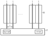
도 1은, 종래의 배터리 모듈의 구성을 개략적으로 도시한 단면도이다.1 is a cross-sectional view schematically showing a configuration of a conventional battery module.
도시한 바와 같이, 일 예로 종래의 배터리 모듈은 다수의 배터리 셀(B)들이 적층된 배터리 셀 적층체와, 상기 배터리 셀(B)들과 상호 간 교번적으로 접촉하도록 배열되어 배터리 셀(B)들과 열교환을 행하는 복수의 냉각 플레이트들(1)과, 복수의 냉각 플레이트(1)들을 냉각시키기 위한 히트싱크(2)를 포함한다. 도 1을 참조하면, 복수의 냉각 플레이트(1)는 상호 간에 배터리 셀(B) 두께의 2배에 해당하는 간격을 갖도록 히트싱크(2)에 결합될 수 있다. 즉, 냉각 플레이트(1) 간의 이격 거리(T)는 조립할 배터리 셀(B)의 두께에 따라 결정되고, 배터리 셀(B)의 규격과 용량은, 배터리 셀(B)이 적용되는 디바이스의 사양에 따라 다양하게 구성될 수 있다. 따라서, 종래의 히트싱크(2)와 냉각 플레이트(1)를 포함하는 배터리 셀 냉각장치는 미리 배터리 셀(B)의 두께에 따라 여러 가지 규격으로 제작된다. 그러나 배터리 셀(B)의 두께는 매우 다양하게 구성될 수 있는데, 이들 모든 배터리 셀(B)들의 냉각장치를 제작하는 것은 경제적인 측면에서 매우 비효율적이며, 더욱이 제조시 조금의 공차라도 있으면, 해당 배터리 셀(B)에 냉각장치를 사용할 수 없게 되는 문제점이 발생할 수 있다. As shown in the drawing, for example, a conventional battery module includes a battery cell stack in which a plurality of battery cells B are stacked, and a battery cell stack B arranged in an alternate contact with the battery cells B, A plurality of
따라서, 본 발명은 상기와 같은 문제점을 해결하기 위해 창안된 것으로서, 두께가 다른 종류의 배터리 셀에도 그대로 사용할 수 있는 호환성을 갖춘 배터리 셀 냉각장치를 제공하는 것이다. SUMMARY OF THE INVENTION Accordingly, the present invention has been made keeping in mind the above problems occurring in the prior art, and it is an object of the present invention to provide a battery cell cooling device having compatibility with a battery cell of a different thickness.
본 발명의 다른 목적 및 장점들은 하기의 설명에 의해서 이해될 수 있으며, 본 발명의 실시예에 의해 보다 분명하게 알게 될 것이다. 또한, 본 발명의 목적 및 장점들은 특허 청구 범위에 나타낸 수단 및 그 조합에 의해 실현될 수 있음을 쉽게 알 수 있을 것이다.Other objects and advantages of the present invention will become apparent from the following description, and it will be understood by those skilled in the art that the present invention is not limited thereto. It will also be readily apparent that the objects and advantages of the invention may be realized and attained by means of the instrumentalities and combinations particularly pointed out in the appended claims.
본 발명의 일 측면에 따르면, 내부에 냉매가 흐르는 냉각 채널이 형성된 중공 구조의 히트싱크; 및 열 전도성 소재의 판상 형태로, 미리 결정된 간격으로 상호 간 이격된 위치에서 상기 히트싱크에 접속되는 복수의 냉각 플레이트를 포함하며, 상기 냉각 플레이트는, 배터리 셀의 일면과 대면하는 흡열부, 상기 흡열부의 단부에서 연장되어 상기 히트싱크에 접속되고, 상기 히트싱크에 접속되는 부위를 축으로 소정 각도 회동 가능하게 마련되는 변위부를 포함하는 배터리 셀 냉각장치가 제공될 수 있다.According to an aspect of the present invention, there is provided a heat sink having a hollow structure in which a cooling channel through which refrigerant flows is formed; And a plurality of cooling plates connected to the heat sink at positions spaced apart from each other at predetermined intervals in a plate form of a thermally conductive material, wherein the cooling plate has a heat absorbing portion facing one surface of the battery cell, And a displaceable portion extending from an end of the housing and connected to the heat sink, the displaceable portion being rotatable by a predetermined angle about a portion connected to the heat sink.
본 발명의 다른 측면에 따르면, 상기 변위부는, 상기 배터리 셀과 상기 히트싱크 사이 공간에서 길이가 신축되도록 주름진 형태로 탄성을 갖도록 마련될 수 있다.According to another aspect of the present invention, the displacement portion may be formed to have elasticity in a corrugated shape such that the length of the displacement portion in the space between the battery cell and the heat sink is expanded and contracted.
본 발명의 또 다른 측면에 따르면, 상기 히트싱크와 상기 복수의 냉각 플레이트는 일체로 형성될 수 있다.According to another aspect of the present invention, the heat sink and the plurality of cooling plates may be integrally formed.
본 발명의 또 다른 측면에 따르면, 상기 냉각 플레이트는, 상기 변위부의 단부에서 상기 히트싱크의 내부까지 연장되어 상기 냉각 채널에 노출되는 말단부를 더 포함할 수 있다.According to another aspect of the present invention, the cooling plate may further include an end portion extending from the end of the displacement portion to the inside of the heat sink and exposed to the cooling channel.
본 발명의 또 다른 측면에 따르면, 상기 말단부는, 끝단이 일 방향 또는 양 방향으로 절곡된 형태로 마련될 수 있다.According to another aspect of the present invention, the distal end may be provided in a shape in which the distal end is bent in one direction or both directions.
본 발명의 또 다른 측면에 따르면, 상기 히트싱크는, 상호 간 조립 가능하게 마련되는 복수의 단위 히트싱크를 포함할 수 있다.According to another aspect of the present invention, the heat sink may include a plurality of unit heat sinks that are assembled to each other.
본 발명의 또 다른 측면에 따르면, 상기 단위 히트싱크는, 일 측면에서 내측으로 함몰 형성된 홈부와, 타 측면에서 외측으로 돌출 형성된 돌출부를 구비하고, 어느 하나의 단위 히트싱크의 돌출부가 다른 하나의 단위 히트싱크의 홈부에 억지끼움될 수 있다.According to another aspect of the present invention, there is provided a unit heat sink comprising: a groove portion formed inwardly inwardly from one side surface; and a protrusion portion protruding outward from the other side surface, wherein protrusions of one unit heat sink are formed in another unit It can be forcedly fitted into the groove of the heat sink.
본 발명의 또 다른 측면에 따르면, 상기 단위 히트싱크는, 상기 복수의 냉각 플레이트 중 하나의 냉각 플레이트와 접속될 수 있다.According to another aspect of the present invention, the unit heat sink may be connected to one of the plurality of cooling plates.
본 발명의 또 다른 측면에 따르면, 상기 단위 히트싱크는, 상기 복수의 냉각 플레이트 중 적어도 2개 이상의 냉각 플레이트와 접속될 수 있다.According to another aspect of the present invention, the unit heat sink may be connected to at least two or more of the plurality of cooling plates.
본 발명의 또 다른 측면에 따르면, 상기 단위 히트싱크와 상기 냉각 플레이트는 일체로 형성될 수 있다.According to another aspect of the present invention, the unit heat sink and the cooling plate may be integrally formed.
본 발명의 또 다른 측면에 따르면, 상기 단위 히트싱크들은 각각, 상기 냉각 채널과, 상기 냉각 채널에 냉매가 유입 및 유출될 수 있도록 유입구와 유출구를 구비하고, 어느 하나의 상기 단위 히트싱크에 구비되는 유출구와 이웃하게 배치되는 다른 하나의 상기 단위 히트싱크에 구비되는 유입구를 연결하는 파이프 라인을 더 포함할 수 있다.According to another aspect of the present invention, each of the unit heat sinks includes the cooling channel, an inlet and an outlet for allowing the refrigerant to flow in and out of the cooling channel, And a pipeline connecting an inlet provided in the other one of the unit heat sinks adjacent to the outlet.
본 발명의 다른 양태에 의하면, 상술한 배터리 셀 냉각장치를 포함하는 배터리 모듈이 제공될 수 있다. According to another aspect of the present invention, a battery module including the battery cell cooling device described above can be provided.
본 발명의 또 다른 양태에 의하면, 상기 배터리 모듈을 포함하는 자동차가 제공될 있다. 상기 자동차는 전기자동차, 하이브리드 전기자동차, 플러그-인 하이브리드 전기자동차 중 어느 하나일 수 있다.According to another aspect of the present invention, there is provided an automobile including the battery module. The automobile may be any one of an electric vehicle, a hybrid electric vehicle, and a plug-in hybrid electric vehicle.
본 발명의 일 측면에 따르면, 두께가 다른 종류의 배터리 셀에도 그대로 사용될 수 있는 호환성을 갖춘 배터리 셀 냉각장치가 제공될 수 있다.According to an aspect of the present invention, there can be provided a compatible battery cell cooling apparatus which can be used as is for battery cells of other kinds of thickness.
본 발명의 다른 측면에 따르면, 적어도 하나의 냉각 플레이트와 일체화된 단위 히트싱크들이 상호 간 조립 가능하게 구성될 수 있다. 따라서 적층되는 배터리 셀의 개수에 따라 배터리 셀 냉각장치를 다양한 형태로 쉽게 구성할 수 있다.According to another aspect of the present invention, unit heat sinks integrated with at least one cooling plate can be configured to be assembled with each other. Therefore, the battery cell cooling apparatus can be easily configured in various forms according to the number of stacked battery cells.
도 1은, 종래의 배터리 모듈의 구성을 개략적으로 도시한 단면도이다.
도 2는, 본 발명의 일 실시예에 따른 배터리 셀 냉각장치의 개략적인 사시도이다.
도 3은, 도 2의 Ⅰ- Ⅰ'에 따른 단면도이다.
도 4는, 본 발명의 일 실시예에 따른 냉각 플레이트의 변형을 자세히 설명하기 위한 도면이다.
도 5는, 본 발명의 일 실시예에 따른 배터리 셀 냉각장치에 두께가 T1인 배터리 셀들을 조립한 상태를 개략적으로 나타내는 사시도이다.
도 6은, 본 발명의 일 실시예에 따른 배터리 셀 냉각장치에 두께가 T2인 배터리 셀들을 조립한 상태를 개략적으로 나타내는 사시도이다.
도 7은, 본 발명의 다른 실시예에 따른 배터리 셀 냉각장치의 사시도이다.
도 8은, 본 발명의 다른 실시예에 따른 하나의 냉각 플레이트와 일체화된 단위 히트싱크와, 이들의 조립 상태를 나타내는 사시도이다.
도 9는 도 7의 평면도이다.
도 10은 도 7의 Ⅱ-Ⅱ'에 따른 단면도이다.
도 11은, 도 8의 냉각 플레이트와 단위 히트싱크의 변형예를 나타내는 사시도이다. 1 is a cross-sectional view schematically showing a configuration of a conventional battery module.
2 is a schematic perspective view of a battery cell cooling apparatus according to an embodiment of the present invention.
3 is a cross-sectional view taken along line I-I 'in Fig.
4 is a view for explaining a modification of the cooling plate according to an embodiment of the present invention in detail.
5 is a perspective view schematically showing a battery cell cooling apparatus according to an embodiment of the present invention in which battery cells having a thickness of T1 are assembled.
6 is a perspective view schematically showing a battery cell cooling apparatus according to an embodiment of the present invention in which battery cells having a thickness T2 are assembled.
7 is a perspective view of a battery cell cooling apparatus according to another embodiment of the present invention.
FIG. 8 is a perspective view showing a unit heat sink integrated with one cooling plate according to another embodiment of the present invention and their assembled state. FIG.
Fig. 9 is a plan view of Fig. 7. Fig.
10 is a cross-sectional view taken along line II-II 'of FIG.
Fig. 11 is a perspective view showing a modified example of the cooling plate and the unit heat sink of Fig. 8;
이하, 첨부된 도면을 참조하여 본 발명의 바람직한 실시예를 상세히 설명하기로 한다. 이에 앞서, 본 명세서 및 청구범위에 사용된 용어나 단어는 통상적이거나 사전적인 의미로 한정해서 해석되어서는 아니 되며, 발명자는 그 자신의 발명을 가장 최선의 방법으로 설명하기 위해 용어의 개념을 적절하게 정의할 수 있다는 원칙에 입각하여 본 발명의 기술적 사상에 부합하는 의미와 개념으로 해석되어야 한다. Hereinafter, preferred embodiments of the present invention will be described in detail with reference to the accompanying drawings. Prior to this, terms and words used in the present specification and claims should not be construed as limited to ordinary or dictionary terms, and the inventor should appropriately interpret the concepts of the terms appropriately It should be construed as meaning and concept consistent with the technical idea of the present invention based on the principle that it can be defined.
또한, 본 발명을 설명함에 있어 관련된 공지 구성 또는 기능에 대한 구체적인 설명이 본 발명의 요지를 흐릴 수 있다고 판단되는 경우에는 그 상세한 설명은 생략한다.In the following description, well-known functions or constructions are not described in detail since they would obscure the invention in unnecessary detail.
본 발명의 실시형태는 통상의 기술자에게 본 발명을 더욱 완전하게 설명하기 위하여 제공되는 것이므로 도면에서의 구성요소들의 형상 및 크기 등은 보다 명확한 설명을 위해 과장되거나 생략되거나 또는 개략적으로 도시될 수 있다. 따라서, 각 구성요소의 크기나 비율은 실제적인 크기나 비율을 전적으로 반영하는 것은 아니다.The embodiments of the present invention are provided to explain the present invention more fully to the ordinary artisan, so that the shape and size of the components in the drawings may be exaggerated, omitted or schematically shown for clarity. Thus, the size or ratio of each component does not entirely reflect the actual size or ratio.
배터리 셀들은 한정된 공간에서 높은 적층률을 제공할 수 있도록 바람직하게는 판상형으로, 일면 또는 양면이 인접한 배터리 셀에 대면하도록 적층 배열되어 배터리 셀 적층체를 형성하고 있을 수 있다. 본 발명에 따른 배터리 셀 냉각장치는 이러한 배터리 셀 적층체에 장착되어 배터리 셀들의 열을 제거하는 장치를 의미한다.The battery cells may be arranged in a stacked manner so as to face a battery cell adjacent to one side or both sides of the battery cell so as to provide a high lamination ratio in a limited space. The battery cell cooling apparatus according to the present invention means a device mounted on such a battery cell stack to remove heat of battery cells.
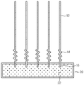
도 2는, 본 발명의 일 실시예에 따른 배터리 셀 냉각장치의 개략적인 사시도이고, 도 3은, 도 2의 Ⅰ- Ⅰ'에 따른 단면도이다.FIG. 2 is a schematic perspective view of a battery cell cooling apparatus according to an embodiment of the present invention, and FIG. 3 is a cross-sectional view taken along line I-I 'of FIG.
도 2 및 도 3을 참조하면, 본 발명의 일 실시예에 따른 배터리 셀 냉각장치(100)는, 복수 개의 냉각 플레이트(10)와 히트싱크(20)를 포함한다. Referring to FIGS. 2 and 3, a battery
냉각 플레이트(10)는 열 전도성 부재로 배터리 셀(B)의 열을 빠르게 흡수하는 역할을 한다. 냉각 플레이트(10)는 배터리 셀(B)의 구성에 따라 복수 개가 마련될 수 있다. 복수의 냉각 플레이트(10)는 미리 결정된 간격으로 상호 간 이격되게 배열된다. 여기서, 상기 미리 결정된 간격은 본 발명에 따른 배터리 셀 냉각장치(100)와 조립될 수 있는 배터리 셀(B)들의 평균적인 두께를 참작하여 결정될 수 있다. 그리고 미리 결정된 간격에는 하나 또는 두 개의 배터리 셀(B)이 위치할 수 있다. 이때, 바람직하게는, 냉각 플레이트(10)의 일면과 배터리 셀(B)의 일면이 서로 밀착될 수 있다. 배터리 셀(B)은 충방전 중 과열되더라도 냉각 플레이트(10)와의 열 접촉에 의해 열을 방출하고 적정 온도를 유지할 수 있다. The
냉각 플레이트(10)는 열 전도성을 가지는 박형으로, 예를 들어, 금속 소재의 시트형 판재가 사용될 수 있다. 상기 금속 소재는 금속 중에서도 열전도성이 높고 경량인 알루미늄 또는 알루미늄 합금이 사용될 수 있지만, 이들만으로 한정되는 것은 아니다. 예컨대 구리, 금, 은도 가능하다. The cooling
보다 구체적으로, 본 발명에 따른 냉각 플레이트(10)는, 흡열부(12), 변위부(14) 및 말단부(16)를 포함한다.More specifically, the cooling
도 2 내지 도 3을 참조하면, 냉각 플레이트(10)는 히트싱크(20)에 수직으로 배치된다. 흡열부(12)는 배터리 셀(B)의 일면과 대면하는 부분으로, 변위부(14)는 흡열부(12)의 단부에서 히트싱크(20)의 몸체까지 연장된 부분으로, 말단부(16)는 히트싱크(20)의 내부의 유로, 즉 냉각 채널(22)에 노출되는 부분으로 한정될 수 있다. 2 to 3, the cooling
흡열부(12)는 배터리 셀(B)의 일면과 직접 접하는 부분으로 배터리 셀(B)에서 발생한 열을 흡수할 수 있다. 흡열부(12)는 배터리 셀(B)과의 접촉면에 공기층이 생겨나지 않도록 매끄럽게 형성한다. 공기층은 열전달율을 떨어뜨리는 요인이 될 수 있다. 도시하지 않았으나, 흡열부(12)와 배터리 셀(B) 사이 접촉면에 TIM(Thermal Interface Material) 등의 열 전도성 시트를 개재하여 공기층을 제거할 수도 있다. The
변위부(14)는 히트싱크(20)에 접속되는 부위를 축으로 소정 각도 회동 가능하게 마련된다. 특히, 상기 변위부(14)는 히트싱크(20)에 접속되는 부위를 축으로 소정 각도 좌,우로 회동 가능하게 마련됨으로서 복수의 냉각 플레이트(10)들 사이의 폭이 변경될 수 있게 한다. The
도 4는, 본 발명의 일 실시예에 따른 냉각 플레이트(10)의 변형을 자세히 설명하기 위한 도면이다. 도 4를 참조하면, 본 실시예에 따른 변위부(14)는, 주름진 형태로 탄성을 갖도록 마련되어 있다. 변위부(14)는 주름 간격이 좁아지거나 넓어짐에 따라 압축 또는 신장될 수 있다. Fig. 4 is a view for explaining a modification of the cooling
이와 같이, 변위부(14)를 주름진 형태로 구성할 경우, 냉각 플레이트(10)의 넓은 면을 향해 외력이 가해지면, 변위부(14)가 신장되면서 히트싱크(20)에 고정된 부위를 축으로 냉각 플레이트(10)가 소정 각도 기울어질 수 있다. 그리고 다시 외력이 없어지면, 복원력에 의해 변위부(14)가 압축되면서 냉각 플레이트(10)가 원상태로 복귀할 수 있다. 예컨대, 도 4에 도시된 바와 같이, 2개의 냉각 플레이트(10) 사이에 배터리 셀(B)들이 완전히 끼워넣어진 상태에서는 배터리 셀(B)들에 의한 인장력(P1)과 변위부(14)의 탄성 복원력(P2)이 균형을 이루어 흡열부(12)와 배터리 셀(B)이 서로 밀착될 수 있다. 이러한 본 실시예에 따른 냉각 플레이트(10)는 변위부(14)의 변형과 복원이 가능하도록 탄성계수가 높은 소재로 제작될 수 있다.When the external force is applied toward the wide surface of the cooling
본 실시예의 변위부(14)는 주름진 형태로 탄성을 갖도록 구성하였으나, 이와 달리 변위부(14)는, 히트싱크(20)와 고정되는 부위를 축으로 소정 각도 회동 가능하게 마련되는 구조라면 어떠한 구조라도 무방할 수 있다. 예컨대, 변위부는, 도시하지 않았으나, 2개의 힌지(hinge)를 이용한 링크 구조로 구성될 수도 있을 것이다. 즉, 하나의 힌지는 흡열부(12)와 변위부의 연결 부위에 마련하고, 나머지 하나의 힌지는 변위부와 히트싱크(20)의 연결 부위에 마련될 수 있다. 이때, 회전 각도가 제한되는 힌지를 사용하여 냉각 플레이트(10)의 기울기를 조절할 수 있다. 이러한 구성에 의하면, 어느 하나의 냉각 플레이트(10)와 이에 이웃한 냉각 플레이트(10) 간의 폭이 조절가능해 질 수 있다. The
말단부(16)는 히트싱크(20) 내부의 냉각 채널(22)에 흐르는 냉매와 직접 접촉하는 부분으로, 흡열부(12)와 변위부(14)로부터 전도된 열을 냉각 채널(22)에 흐르는 냉매에 빠르게 방출시킨다. 도시하지 않았으나, 본 실시예와 달리, 말단부(16)는 끝단이 일 방향 또는 양 방향으로 절곡된 형태로 마련될 수도 있다. 다시 말하면, 유효 방열 면적을 넓히기 위해 말단부의 단면이 대략 "T" 자 형태가 되도록 말단부(16)를 구성할 수 있다. 유체와 고체 간의 열 전달은 유효 방열 면적에 비례하므로, 절곡된 형태의 말단부(16)가 열전달 측면에서 효과적일 수 있다. 다만, 본 발명의 권리범위가 이러한 사항에 반드시 한정되는 것은 아니다. 즉, 본 실시예와 달리, 냉각 플레이트(10)는 히트싱크(20)의 몸체에만 연결되도록 하고 말단부(16)를 생략할 수도 있다. The
히트싱크(20)는 대략 사각 박스 형태로, 내부에 냉매가 흐르는 냉각 채널(22)과, 냉매를 유입 및 유출시키기 위한 유입구와 유출구를 포함한다. 그리고 유입구와 유출구에는 각각 냉매를 공급하기 위한 배관(21)이 연결될 수 있다. 상기 냉매는 냉각 채널(22)에서 용이하게 흐르면서 냉각성이 우수한 유체이면 특별한 제한은 없으며, 기체 또는 액체일 수 있다. 예를 들어, 잠열이 높아 냉각 효율성을 극대화할 수 있는 물일 수 있다. 그러나 이것에 한정하지 않고, 흐름이 발생하는 것이면, 부동액, 가스 냉매, 공기 등이어도 좋다. The
이러한 히트싱크(20)는 열 접촉에 의해 냉각 플레이트(10)의 열을 흡수한다. 그리고 히트싱크(20)는 냉각 채널(22)을 따라 흐르는 냉매에 의해 냉각된다. 즉, 온도 구배에 의해 배터리 셀(B)들의 열은 복수의 냉각 플레이트(10)를 통해 히트싱크(20)에 전달되고, 히트싱크(20)는 냉매에 의해 냉각됨으로서, 배터리 셀(B)들의 온도가 적정하게 유지될 수 있다. This
본 실시예에서 히트싱크(20)와 복수의 냉각 플레이트(10)는 서로 일체로 제작될 수 있다. 히트싱크(20)와 복수의 냉각 플레이트(10)가 일체형으로 제작되면, 히트싱크(20)와 냉각 플레이트(10) 간의 접촉 열저항에 따른 손실이 발생하지 않을 수 있다. 여기서 접촉 열저항이란, 서로 다른 물체가 접촉을 하게 되면 발생되는 문제로 표면 조도로 인하여 원활하게 열이 이동되는 것을 저해하는 요인으로 작용하게 것을 의미한다.In the present embodiment, the
도 5는, 본 발명의 일 실시예에 따른 배터리 셀 냉각장치(100)에 두께가 T1인 배터리 셀(B)들을 조립한 상태를 개략적으로 나타내는 사시도이고, 도 6은, 본 발명의 일 실시예에 따른 배터리 셀 냉각장치(100)에 두께가 T2인 배터리 셀(B)들을 조립한 상태를 개략적으로 나타내는 사시도이다. FIG. 5 is a perspective view schematically showing a state in which battery cells B having a
배터리 셀 냉각장치(100)는 배터리 셀(B) 적층체 구성에 따라 상부, 하부, 좌측부, 및 우측부 중 적어도 어느 한 곳에서 장착될 수 있다. 즉, 본 발명에 따른 배터리 셀 냉각장치(100)는, 배터리 셀(B)들이 수직 방향으로 층상으로 적층체를 형성하는 경우 배터리 셀(B) 적층체의 좌측부 및 우측부 중 적어도 어느 한 곳에 장착될 수 있고, 배터리 셀(B)들이 세워져 수평 방향으로 적층체를 형성하는 경우 배터리 셀(B) 적층체의 상부 및 하부 중 적어도 어느 한 곳에 장착될 수 있다. 도 5 및 도 6은 후자의 경우를 개략적으로 나타내는 도면에 해당한다. The battery
먼저, 도 5를 참조하면, 본 실시예에 따른 배터리 셀 냉각장치(100)는, 히트싱크(20)와 5개의 냉각 플레이트(10)를 포함한다. 그리고 냉각 플레이트(10)들은 T1×2의 간격을 갖도록 배열되어 있다. 따라서, 두께 T1인 배터리 셀(B)들을 2개를 한 조로 각각의 냉각 플레이트(10)들 사이 공간에 개재시킬 수 있다. 물론, 이때 냉각 플레이트(10)의 변위부(14)는 변형이 거의 일어나지 않는다. Referring to FIG. 5, a battery
또한, 도 6에 도시된 바와 같이, 배터리 셀 냉각장치(100)는, 두께가 T2 (T1<T2)로 두께가 T1인 배터리 셀(B)들과 규격이 다른 배터리 셀(B)들과 조립될 수도 있다. 6, the battery
배터리 셀(B)의 두께가 T2인 경우, 2개의 배터리 셀(B)을 냉각 플레이트(10) 사이에 개재하기 위해서는, 특히 흡열부(12)들 사이에 T2*2 만큼의 간격이 필요하다. 이를 위해 전술한 바와 같이, 변위부(14)가 히트싱크(20)에 접속되는 부위를 축으로 소정 각도 회동함으로써 흡열부(12)들의 폭이 같이 넓혀질 수 있다. 즉, 변위부(14)가 주름진 형태로 탄성을 갖도록 되어 있어 2개의 냉각 플레이트(10)를 벌려서 그 사이 공간에 배터리 셀(B)들을 끼워넣을 수 있다. 배터리 셀(B)들이 완전히 끼워넣어진 상태에서는 배터리 셀(B)들에 의한 인장력과 변위부(14)의 탄성 복원력이 균형을 이루어 흡열부(12)와 배터리 셀(B)이 서로 밀착될 수 있다. In the case where the thickness of the battery cell B is T2, in order to interpose the two battery cells B between the cooling
보다 구체적으로, 본 실시예에 따른 냉각장치(100)와 배터리 셀(B)들의 조립 상태를 살펴보면, 도 6에 도시된 냉각 플레이트(10)의 세번째 변위부(14)를 기준으로 양쪽에 배열된 변위부(14)들은 서로 반대 방향으로 기울어진 상태가 되고, 흡열부(12)들은 T2*2의 간격을 갖게된다. 여기서 각 변위부(14)의 기울기는 세번째 냉각 플레이트(10)를 기준으로 멀어질수록 커질 수 있다. 첫번째, 두번째 변위부(14)의 변형 각도가 θ₁과 θ₂라면, (θ₁> θ₂) 네번째, 다섯번째 변위부(14)의 변형 각도는 -θ₂,-θ₁일 수 있다. 즉, 변위부(14) 전체 변형 각도의 합은 0도 일 수 있다. The assembled state of the
한편, 본 실시예에 따른 배터리 셀 냉각장치(100)는 5개의 냉각 플레이트(10)를 포함하도록 구성하였으나, 적층되는 배터리 셀(B)들의 개수에 따라 5개 이하이거나 그 이상의 냉각 플레이트(10)를 포함하도록 구성할 수 있음은 물론이다. The battery
이와 같이 본 발명의 일 측면에 따르면, 냉각 플레이트(10)들의 간격 조절이 가능하게 구성됨으로서, 소정의 범위 내에서 배터리 셀(B)들이 두께가 다르더라도 냉각 장치를 새로이 제작할 필요가 없다. 또한, 냉각장치(100) 제조시 냉각 플레이트(10)들 간의 간격에 다소 공차가 있더라도 배터리 셀(B) 조립이 가능해져 조립 편의성이 향상될 수 있다. As described above, according to the aspect of the present invention, it is possible to adjust the spacing of the cooling
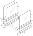
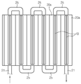
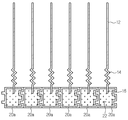
도 7은, 본 발명의 다른 실시예에 따른 배터리 셀 냉각장치(100')의 사시도이고, 도 8은, 본 발명의 다른 실시예에 따른 하나의 냉각 플레이트(10)와 일체화된 단위 히트싱크(20a)와, 이들의 조립 상태를 나타내는 사시도이며, 도 9는 도 7의 평면도이고, 도 10은 도 7의 Ⅱ-Ⅱ'에 따른 단면도이다. FIG. 7 is a perspective view of a battery cell cooling apparatus 100 'according to another embodiment of the present invention, and FIG. 8 is a cross-sectional view of a unit heat sink Fig. 9 is a plan view of Fig. 7, and Fig. 10 is a cross-sectional view taken along line II-II 'of Fig. 7.
이들 도면을 참조하여 본 발명의 다른 실시예에 따른 배터리 셀 냉각장치(100')를 설명하기로 한다. 전술한 실시예와 동일한 부재번호는 동일한 부재를 나타내며, 동일한 부재에 대한 중복된 설명은 생략하기로 하고, 전술한 실시예와의 구성상 차이점을 위주로 설명하기로 한다. A battery cell cooling apparatus 100 'according to another embodiment of the present invention will be described with reference to these drawings. The same reference numerals as those in the above-described embodiment denote the same members, and a duplicated description of the same members will be omitted, and differences from the above-described exemplary embodiment will be mainly described.
본 실시예에 따른 히트싱크(20')는 상호 간 조립 가능하게 마련되는 복수의 단위 히트싱크(20a)를 포함한다. 그리고 단위 히트싱크(20a)에는 하나의 냉각 플레이트(10)가 접속되도록 구성한다. 이때, 단위 히트싱크(20a)와 하나의 냉각 플레이트(10)는 전술한 실시예와 같이 일체로 제작될 수 있다. The heat sink 20 'according to the present embodiment includes a plurality of
각각의 상기 단위 히트싱크(20a)는 내부에 유로를 형성하는 냉각 채널(22)과, 냉각 채널(22)의 전후에는 각각 유입구(23)와 유출구(24)를 구비할 수 있다. 유입구(23)와 유출구(24)를 개념상 구분하고 있으나, 이들은 단위 히트싱크(20a)에 형성된 개구로 이해될 수 있다. Each of the
그리고 단위 히트싱크(20a)는, 도 8에 도시된 바와 같이, 일 측면에서 내측으로 함몰 형성된 홈부(26)와, 타 측면에서 외측으로 돌출 형성된 돌출부(27)를 더 구비할 수 있다. 이에 어느 하나의 단위 히트싱크(20a)의 돌출부(27)가 다른 하나의 단위 히트싱크(20a)의 홈부(26)에 억지끼움됨으로서 두개의 단위 히트싱크(20a)들이 한 몸체가 될 수 있다. 여기서, 도 8과 같이, 단위 히트싱크(20a)가 직육면체의 형상의 박스 형태로 마련될 때, 유입구(23)와 유출구(24)가 구비되는 부분을 단위 히트싱크(20)의 정면과 배면이라고 하면, 상기 일 측면과 타 측면은 좌측면과 우측면을 의미할 수 있다. As shown in FIG. 8, the
도 7 및 도 9 내지 도 10을 참조하면, 단위 히트싱크(20a)의 조립에 의해 냉각 채널(22)들은 서로 구획되어 있다. 이들 구획된 냉각 채널(22)들은 별도의 연결 파이프(25)로 연결될 수 있다. 즉, 연결 파이프(25)는 어느 하나의 단위 히트싱크(20)에 구비되는 유출구(24)와 이웃하게 배치되는 다른 하나의 단위 히트싱크(20)에 구비되는 유입구(23)를 연결한다. 따라서 외부에서 유입된 냉매는 구획된 냉각 채널(22)들을 따라 지그재그 형태로 흐를 수 있다. Referring to Figs. 7 and 9 to 10, the cooling
이와 같이 본 실시예에 따르면, 단위 히트싱크(20a)들을 필요한 개수만큼 조립함으로서 냉각장치(100)를 다양한 형태로 쉽게 제작할 수 있다. 따라서, 다양한 구성을 갖는 배터리 셀(B) 적층체에 대한, 냉각장치(100)의 설치 및 운용이 매우 간편해질 수 있다. As described above, according to the present embodiment, by assembling the necessary number of
도 11은, 도 8의 냉각 플레이트(10)와 단위 히트싱크(20b)의 변형예를 나타내는 사시도이다. 11 is a perspective view showing a modified example of the cooling
전술한 단위 히트싱크(20a)와 본 변형예에 따른 단위 히트싱크(20b)를 구분하기 위해 전자는 제1 단위 히트싱크(20a)로 지칭하고, 후자는 제2 단위 히트싱크(20b)로 지칭한다. The electrons are referred to as a first
도 8의 제1 단위 히트싱크(20a)에는 하나의 냉각 플레이트(10)가 일체로 구성되어 있음에 비해, 본 변형예에 따른 제2 단위 히트싱크(20b)는, 도 11에 도시된 바와 같이, 전술한 제1 단위 히트싱크(20a)의 폭의 대략 2배로 제작될 수 있고, 두개의 냉각 플레이트(10)와 일체로 구성될 수 있다. 이러한 제2 단위 히트싱크(20b)들을 복수 개 조합하거나, 제2 단위 히트싱크(20b)와 제1 단위 히트싱크(20a)를 복수 개 조합할 경우, 조립 편의성이 높아져 보다 간편하고 효율적으로 배터리 셀 냉각장치(100')를 구성할 수 있다. 물론, 도시하지 않았으나, 본 변형예와 유사하게 3개 이상의 냉각 플레이트(10)와 단위 히트싱크를 일체로 제작할 수도 있을 것이다. 11, one
한편, 본 발명에 따른 배터리 모듈은, 상술한 배터리 셀 냉각장치(100,100')를 하나 이상 포함할 수 있다. 또한, 배터리 모듈은, 배터리 셀 적층체를 커버하기 위한 케이스, 배터리 셀(B)들의 충방전을 제어하기 위한 각종 장치, 이를테면 BMS, 전류 센서, 퓨즈 등이 더 포함될 수 있다. Meanwhile, the battery module according to the present invention may include one or more battery
또한, 본 발명에 따른 자동차는 본 발명에 따른 배터리 모듈을 포함할 수 있다. 상기 배터리 모듈은 전기 자동차나 하이브리드 자동차와 같은 자동차에 적용될 수 있을 뿐만 아니라 IT 제품군 등에도 적용될 수 있다.Further, the automobile according to the present invention may include a battery module according to the present invention. The battery module can be applied not only to automobiles such as electric vehicles and hybrid vehicles but also to IT product groups and the like.
이상, 본 발명의 바람직한 실시예에 대해 도시하고 설명하였으나, 본 발명은 상술한 특정의 바람직한 실시예에 한정되지 아니하며, 청구범위에서 청구하는 본 발명의 요지를 벗어남이 없이 당해 발명이 속하는 기술분야에서 통상의 지식을 가진 자라면 누구든지 다양한 변형 실시가 가능한 것은 물론이고, 그와 같은 변경은 청구범위 기재의 범위 내에 있게 된다.While the present invention has been particularly shown and described with reference to exemplary embodiments thereof, it is to be understood that the invention is not limited to the disclosed exemplary embodiments, but many variations and modifications may be made without departing from the spirit and scope of the invention as defined in the appended claims. It will be understood by those skilled in the art that various changes in form and detail may be made therein without departing from the scope of the appended claims.
한편, 본 명세서에서는. 상, 하, 좌, 우 등과 같이 방향을 나타내는 용어가 사용되었으나, 이러한 용어는 설명의 편의를 위한 것일 뿐, 관측자의 보는 위치나 대상의 놓여져 있는 위치 등에 따라 다르게 표현될 수 있음은 본 발명의 당업자에게 자명하다.On the other hand, in the present specification. It is to be understood that the terminology such as up, down, left, right, etc., is used for convenience of explanation, but can be expressed differently depending on the viewing position of the observer or the position of the object. To be clear to.
100: 배터리 셀 냉각장치
10 : 냉각 플레이트
12: 흡열부
14: 변위부
16: 말단부
20: 히트싱크
22: 냉각 채널
26: 홈부
27: 돌출부
20a,20b : 단위 히트싱크100: battery cell cooling device 10: cooling plate
12: heat absorbing part 14: displacement part
16: terminal 20: heat sink
22: cooling channel 26: groove
27:
Claims (13)
열 전도성 소재의 판상 형태로, 미리 결정된 간격으로 상호 간 이격된 위치에서 상기 히트싱크에 접속되는 복수의 냉각 플레이트를 포함하며,
상기 냉각 플레이트는,
배터리 셀의 일면과 대면하는 흡열부, 상기 흡열부의 단부에서 연장되어 상기 히트싱크에 접속되고, 상기 히트싱크에 접속되는 부위를 축으로 소정 각도 회동 가능하게 마련되는 변위부를 포함하는 것을 특징으로 하는 배터리 셀 냉각장치.A heat sink having a hollow structure in which a cooling channel through which a coolant flows is formed; And
And a plurality of cooling plates connected to the heat sink at positions spaced apart from each other at predetermined intervals in a plate form of a thermally conductive material,
Wherein the cooling plate comprises:
And a displaceable portion extending from an end of the heat absorbing portion and connected to the heat sink, the displaceable portion being provided so as to be rotatable by a predetermined angle about a portion connected to the heat sink, the heat absorbing portion facing one surface of the battery cell, Cell cooling device.
상기 변위부는, 상기 배터리 셀과 상기 히트싱크 사이 공간에서 길이가 신축되도록 주름진 형태로 탄성을 갖도록 마련되는 것을 특징으로 하는 배터리 셀 냉각장치. The method according to claim 1,
Wherein the displacement portion is resiliently formed in a corrugated shape so that a length of the displaceable portion is elongated in a space between the battery cell and the heat sink.
상기 히트싱크와 상기 복수의 냉각 플레이트는 일체로 형성되는 것을 특징으로 하는 배터리 셀 냉각장치.The method according to claim 1,
Wherein the heat sink and the plurality of cooling plates are integrally formed.
상기 냉각 플레이트는,
상기 변위부의 단부에서 상기 히트싱크의 내부까지 연장되어 상기 냉각 채널에 노출되는 말단부를 더 포함하는 것을 특징으로 하는 배터리 셀 냉각장치. The method according to claim 1,
Wherein the cooling plate comprises:
And a distal end portion extending from the end of the displacement portion to the inside of the heat sink and exposed to the cooling channel.
상기 말단부는, 끝단이 일 방향 또는 양 방향으로 절곡된 형태로 마련되는 것을 특징으로 하는 배터리 셀 냉각장치. 5. The method of claim 4,
Wherein the distal end portion is provided in a shape in which the tip is bent in one direction or both directions.
상기 히트싱크는, 상호 간 조립 가능하게 마련되는 복수의 단위 히트싱크를 포함하는 것을 특징으로 하는 배터리 셀 냉각장치. The method according to claim 1,
Wherein the heat sink includes a plurality of unit heat sinks that are assemblable to each other.
상기 단위 히트싱크는, 일 측면에서 내측으로 함몰 형성된 홈부와, 타 측면에서 외측으로 돌출 형성된 돌출부를 구비하고,
어느 하나의 단위 히트싱크의 돌출부가 다른 하나의 단위 히트싱크의 홈부에 억지끼움되는 것을 특징으로 하는 배터리 셀 냉각장치. The method according to claim 6,
Wherein the unit heat sink includes a groove portion formed to be recessed inwardly from one side surface and a protrusion portion protruding outward from the other side surface,
And protruding portions of any one of the unit heat sinks are constrained in the groove portions of the other unit heat sink.
상기 단위 히트싱크는, 상기 복수의 냉각 플레이트 중 하나의 냉각 플레이트와 접속되는 것을 특징으로 하는 배터리 셀 냉각장치. The method according to claim 6,
Wherein the unit heat sink is connected to one cooling plate of the plurality of cooling plates.
상기 단위 히트싱크는, 상기 복수의 냉각 플레이트 중 적어도 2개 이상의 냉각 플레이트와 접속되는 것을 특징으로 하는 배터리 셀 냉각장치. The method according to claim 6,
Wherein the unit heat sink is connected to at least two cooling plates of the plurality of cooling plates.
상기 단위 히트싱크와 상기 냉각 플레이트는 일체로 형성되는 것을 특징으로 하는 배터리 셀 냉각장치. 10. The method according to claim 8 or 9,
Wherein the unit heat sink and the cooling plate are integrally formed.
상기 단위 히트싱크들은 각각, 상기 냉각 채널과, 상기 냉각 채널에 냉매가 유입 및 유출될 수 있도록 유입구와 유출구를 구비하고,
어느 하나의 상기 단위 히트싱크에 구비되는 유출구와 이웃하게 배치되는 다른 하나의 상기 단위 히트싱크에 구비되는 유입구를 연결하는 파이프 라인을 더 포함하는 것을 특징으로 하는 배터리 셀 냉각장치.The method according to claim 6,
The unit heat sinks each have the cooling channel and an inlet and an outlet to allow the refrigerant to flow in and out of the cooling channel,
Further comprising a pipeline connecting an outlet provided in any one of the unit heat sinks and an inlet port provided in another one of the unit heat sinks disposed adjacent to the unit heat sink.
An automobile comprising a battery module according to claim 14.
Priority Applications (1)
| Application Number | Priority Date | Filing Date | Title |
|---|---|---|---|
| KR1020150084482A KR102025861B1 (en) | 2015-06-15 | 2015-06-15 | Cooling Apparatus for Battery Cell |
Applications Claiming Priority (1)
| Application Number | Priority Date | Filing Date | Title |
|---|---|---|---|
| KR1020150084482A KR102025861B1 (en) | 2015-06-15 | 2015-06-15 | Cooling Apparatus for Battery Cell |
Publications (2)
| Publication Number | Publication Date |
|---|---|
| KR20160147565A true KR20160147565A (en) | 2016-12-23 |
| KR102025861B1 KR102025861B1 (en) | 2019-09-26 |
Family
ID=57736307
Family Applications (1)
| Application Number | Title | Priority Date | Filing Date |
|---|---|---|---|
| KR1020150084482A KR102025861B1 (en) | 2015-06-15 | 2015-06-15 | Cooling Apparatus for Battery Cell |
Country Status (1)
| Country | Link |
|---|---|
| KR (1) | KR102025861B1 (en) |
Cited By (5)
| Publication number | Priority date | Publication date | Assignee | Title |
|---|---|---|---|---|
| KR20190018107A (en) * | 2017-08-11 | 2019-02-21 | 현대자동차주식회사 | Battery module |
| CN109860952A (en) * | 2019-03-13 | 2019-06-07 | 郑州工业应用技术学院 | A kind of adjustable radiator structure of new energy car battery |
| EP3611776A1 (en) * | 2018-08-17 | 2020-02-19 | Hyundai Motor Company | Battery module |
| KR102628603B1 (en) * | 2022-12-16 | 2024-01-25 | 인지컨트롤스 주식회사 | Battery pack |
| WO2024063594A1 (en) * | 2022-09-22 | 2024-03-28 | 인지컨트롤스 주식회사 | Battery pack |
Families Citing this family (1)
| Publication number | Priority date | Publication date | Assignee | Title |
|---|---|---|---|---|
| KR102328975B1 (en) | 2019-12-20 | 2021-11-19 | 고려대학교 산학협력단 | Battery module |
Citations (4)
| Publication number | Priority date | Publication date | Assignee | Title |
|---|---|---|---|---|
| KR20120086657A (en) * | 2011-01-26 | 2012-08-03 | 주식회사 엘지화학 | Cooling Member of Improved Assembly Efficiency and Battery Module Employed with the Same |
| KR20130008142A (en) * | 2011-07-12 | 2013-01-22 | 에스케이이노베이션 주식회사 | Secondary battery pack |
| KR20140014413A (en) * | 2012-07-19 | 2014-02-06 | 에스케이이노베이션 주식회사 | Battery module assembly |
| KR20140147166A (en) * | 2013-06-17 | 2014-12-30 | 현대자동차주식회사 | Battery pack air cooling structure provided with thermoelectric element and method thereof |
-
2015
- 2015-06-15 KR KR1020150084482A patent/KR102025861B1/en active IP Right Grant
Patent Citations (4)
| Publication number | Priority date | Publication date | Assignee | Title |
|---|---|---|---|---|
| KR20120086657A (en) * | 2011-01-26 | 2012-08-03 | 주식회사 엘지화학 | Cooling Member of Improved Assembly Efficiency and Battery Module Employed with the Same |
| KR20130008142A (en) * | 2011-07-12 | 2013-01-22 | 에스케이이노베이션 주식회사 | Secondary battery pack |
| KR20140014413A (en) * | 2012-07-19 | 2014-02-06 | 에스케이이노베이션 주식회사 | Battery module assembly |
| KR20140147166A (en) * | 2013-06-17 | 2014-12-30 | 현대자동차주식회사 | Battery pack air cooling structure provided with thermoelectric element and method thereof |
Cited By (7)
| Publication number | Priority date | Publication date | Assignee | Title |
|---|---|---|---|---|
| KR20190018107A (en) * | 2017-08-11 | 2019-02-21 | 현대자동차주식회사 | Battery module |
| EP3442049B1 (en) * | 2017-08-11 | 2023-08-02 | Hyundai Motor Company | Battery module |
| EP3611776A1 (en) * | 2018-08-17 | 2020-02-19 | Hyundai Motor Company | Battery module |
| CN109860952A (en) * | 2019-03-13 | 2019-06-07 | 郑州工业应用技术学院 | A kind of adjustable radiator structure of new energy car battery |
| CN109860952B (en) * | 2019-03-13 | 2021-04-16 | 郑州工业应用技术学院 | Adjustable heat radiation structure for new energy automobile battery |
| WO2024063594A1 (en) * | 2022-09-22 | 2024-03-28 | 인지컨트롤스 주식회사 | Battery pack |
| KR102628603B1 (en) * | 2022-12-16 | 2024-01-25 | 인지컨트롤스 주식회사 | Battery pack |
Also Published As
| Publication number | Publication date |
|---|---|
| KR102025861B1 (en) | 2019-09-26 |
Similar Documents
| Publication | Publication Date | Title |
|---|---|---|
| JP6730526B2 (en) | Battery pack with crash beam structure | |
| KR101780037B1 (en) | Cooling device for battery cell and battery module comprising the same | |
| KR101586197B1 (en) | Battery Pack Having Novel Cooling Structure | |
| KR101205180B1 (en) | Cooling Member of Compact Structure and Excellent Stability and Battery Module Employed with the Same | |
| KR102005488B1 (en) | Cell Cover for secondary battery and battery module including the same | |
| KR101560561B1 (en) | Battery Module with Compact Structure and Excellent Heat Radiation Characteristics and Middle or Large-sized Battery Pack Employed with the Same | |
| KR102025861B1 (en) | Cooling Apparatus for Battery Cell | |
| KR101205181B1 (en) | Cooling Member of Novel Structure and Battery Module Employed with the Same | |
| KR102058688B1 (en) | Battery Module of Indirect Cooling | |
| JP7418558B2 (en) | Battery module and battery pack containing it | |
| JP7353503B2 (en) | Battery packs and devices containing them | |
| JP7442920B2 (en) | Battery module and battery pack containing it | |
| KR20120086408A (en) | Cooling Member of Improved Cooling Efficiency and Battery Module Employed with the Same | |
| JP7436125B2 (en) | Battery module and battery pack containing it | |
| KR102358425B1 (en) | Battery module | |
| KR20170043321A (en) | Battery Module improved heat conductive structure | |
| CN114586227A (en) | Battery pack and device including the same | |
| CN216958206U (en) | Battery module and battery pack including the same | |
| KR102453307B1 (en) | Battery module and battery pack including the same | |
| JP2024504809A (en) | Battery module and battery pack containing it | |
| JP2023546083A (en) | Battery module and battery pack containing it | |
| JP2023554656A (en) | Battery packs and devices containing them | |
| KR20220129324A (en) | Battery module and battery pack including the same | |
| JP2023540073A (en) | Flame arrester and battery pack containing it | |
| KR20210107472A (en) | Battery module and battery pack including the same |
Legal Events
| Date | Code | Title | Description |
|---|---|---|---|
| A201 | Request for examination | ||
| E902 | Notification of reason for refusal | ||
| E701 | Decision to grant or registration of patent right |