EP3722932B1 - Display control device and display control method - Google Patents
Display control device and display control method Download PDFInfo
- Publication number
- EP3722932B1 EP3722932B1 EP20169256.3A EP20169256A EP3722932B1 EP 3722932 B1 EP3722932 B1 EP 3722932B1 EP 20169256 A EP20169256 A EP 20169256A EP 3722932 B1 EP3722932 B1 EP 3722932B1
- Authority
- EP
- European Patent Office
- Prior art keywords
- display
- arrangement region
- region
- objects
- display control
- Prior art date
- Legal status (The legal status is an assumption and is not a legal conclusion. Google has not performed a legal analysis and makes no representation as to the accuracy of the status listed.)
- Active
Links
- 238000000034 method Methods 0.000 title claims description 27
- 230000008859 change Effects 0.000 claims description 52
- 238000006243 chemical reaction Methods 0.000 claims description 5
- 238000010586 diagram Methods 0.000 description 31
- 230000006870 function Effects 0.000 description 31
- 230000004048 modification Effects 0.000 description 26
- 238000012986 modification Methods 0.000 description 26
- 230000001419 dependent effect Effects 0.000 description 14
- 238000001514 detection method Methods 0.000 description 10
- 238000004378 air conditioning Methods 0.000 description 7
- 230000006978 adaptation Effects 0.000 description 5
- 230000000694 effects Effects 0.000 description 5
- 238000009333 weeding Methods 0.000 description 4
- 238000004891 communication Methods 0.000 description 3
- 102100034112 Alkyldihydroxyacetonephosphate synthase, peroxisomal Human genes 0.000 description 2
- 101000799143 Homo sapiens Alkyldihydroxyacetonephosphate synthase, peroxisomal Proteins 0.000 description 2
- 230000009471 action Effects 0.000 description 2
- 230000004913 activation Effects 0.000 description 2
- 238000000848 angular dependent Auger electron spectroscopy Methods 0.000 description 2
- 239000000470 constituent Substances 0.000 description 2
- 230000014509 gene expression Effects 0.000 description 2
- 239000004973 liquid crystal related substance Substances 0.000 description 2
- 230000036760 body temperature Effects 0.000 description 1
- 238000004364 calculation method Methods 0.000 description 1
- 230000009849 deactivation Effects 0.000 description 1
- 230000000593 degrading effect Effects 0.000 description 1
- 238000012886 linear function Methods 0.000 description 1
- 230000003287 optical effect Effects 0.000 description 1
- 239000013307 optical fiber Substances 0.000 description 1
- 230000010355 oscillation Effects 0.000 description 1
- 230000001151 other effect Effects 0.000 description 1
- 230000002093 peripheral effect Effects 0.000 description 1
- 230000029058 respiratory gaseous exchange Effects 0.000 description 1
- 239000012780 transparent material Substances 0.000 description 1
- 238000009966 trimming Methods 0.000 description 1
- 230000000007 visual effect Effects 0.000 description 1
Images


Classifications
-
- G—PHYSICS
- G06—COMPUTING; CALCULATING OR COUNTING
- G06F—ELECTRIC DIGITAL DATA PROCESSING
- G06F3/00—Input arrangements for transferring data to be processed into a form capable of being handled by the computer; Output arrangements for transferring data from processing unit to output unit, e.g. interface arrangements
- G06F3/01—Input arrangements or combined input and output arrangements for interaction between user and computer
- G06F3/048—Interaction techniques based on graphical user interfaces [GUI]
- G06F3/0487—Interaction techniques based on graphical user interfaces [GUI] using specific features provided by the input device, e.g. functions controlled by the rotation of a mouse with dual sensing arrangements, or of the nature of the input device, e.g. tap gestures based on pressure sensed by a digitiser
- G06F3/0488—Interaction techniques based on graphical user interfaces [GUI] using specific features provided by the input device, e.g. functions controlled by the rotation of a mouse with dual sensing arrangements, or of the nature of the input device, e.g. tap gestures based on pressure sensed by a digitiser using a touch-screen or digitiser, e.g. input of commands through traced gestures
-
- G—PHYSICS
- G09—EDUCATION; CRYPTOGRAPHY; DISPLAY; ADVERTISING; SEALS
- G09G—ARRANGEMENTS OR CIRCUITS FOR CONTROL OF INDICATING DEVICES USING STATIC MEANS TO PRESENT VARIABLE INFORMATION
- G09G5/00—Control arrangements or circuits for visual indicators common to cathode-ray tube indicators and other visual indicators
- G09G5/36—Control arrangements or circuits for visual indicators common to cathode-ray tube indicators and other visual indicators characterised by the display of a graphic pattern, e.g. using an all-points-addressable [APA] memory
- G09G5/37—Details of the operation on graphic patterns
-
- G—PHYSICS
- G06—COMPUTING; CALCULATING OR COUNTING
- G06F—ELECTRIC DIGITAL DATA PROCESSING
- G06F3/00—Input arrangements for transferring data to be processed into a form capable of being handled by the computer; Output arrangements for transferring data from processing unit to output unit, e.g. interface arrangements
- G06F3/01—Input arrangements or combined input and output arrangements for interaction between user and computer
- G06F3/048—Interaction techniques based on graphical user interfaces [GUI]
- G06F3/0481—Interaction techniques based on graphical user interfaces [GUI] based on specific properties of the displayed interaction object or a metaphor-based environment, e.g. interaction with desktop elements like windows or icons, or assisted by a cursor's changing behaviour or appearance
- G06F3/0482—Interaction with lists of selectable items, e.g. menus
-
- B—PERFORMING OPERATIONS; TRANSPORTING
- B60—VEHICLES IN GENERAL
- B60K—ARRANGEMENT OR MOUNTING OF PROPULSION UNITS OR OF TRANSMISSIONS IN VEHICLES; ARRANGEMENT OR MOUNTING OF PLURAL DIVERSE PRIME-MOVERS IN VEHICLES; AUXILIARY DRIVES FOR VEHICLES; INSTRUMENTATION OR DASHBOARDS FOR VEHICLES; ARRANGEMENTS IN CONNECTION WITH COOLING, AIR INTAKE, GAS EXHAUST OR FUEL SUPPLY OF PROPULSION UNITS IN VEHICLES
- B60K35/00—Instruments specially adapted for vehicles; Arrangement of instruments in or on vehicles
- B60K35/20—Output arrangements, i.e. from vehicle to user, associated with vehicle functions or specially adapted therefor
- B60K35/28—Output arrangements, i.e. from vehicle to user, associated with vehicle functions or specially adapted therefor characterised by the type of the output information, e.g. video entertainment or vehicle dynamics information; characterised by the purpose of the output information, e.g. for attracting the attention of the driver
-
- B—PERFORMING OPERATIONS; TRANSPORTING
- B60—VEHICLES IN GENERAL
- B60K—ARRANGEMENT OR MOUNTING OF PROPULSION UNITS OR OF TRANSMISSIONS IN VEHICLES; ARRANGEMENT OR MOUNTING OF PLURAL DIVERSE PRIME-MOVERS IN VEHICLES; AUXILIARY DRIVES FOR VEHICLES; INSTRUMENTATION OR DASHBOARDS FOR VEHICLES; ARRANGEMENTS IN CONNECTION WITH COOLING, AIR INTAKE, GAS EXHAUST OR FUEL SUPPLY OF PROPULSION UNITS IN VEHICLES
- B60K35/00—Instruments specially adapted for vehicles; Arrangement of instruments in or on vehicles
- B60K35/65—Instruments specially adapted for specific vehicle types or users, e.g. for left- or right-hand drive
- B60K35/654—Instruments specially adapted for specific vehicle types or users, e.g. for left- or right-hand drive the user being the driver
-
- B—PERFORMING OPERATIONS; TRANSPORTING
- B60—VEHICLES IN GENERAL
- B60K—ARRANGEMENT OR MOUNTING OF PROPULSION UNITS OR OF TRANSMISSIONS IN VEHICLES; ARRANGEMENT OR MOUNTING OF PLURAL DIVERSE PRIME-MOVERS IN VEHICLES; AUXILIARY DRIVES FOR VEHICLES; INSTRUMENTATION OR DASHBOARDS FOR VEHICLES; ARRANGEMENTS IN CONNECTION WITH COOLING, AIR INTAKE, GAS EXHAUST OR FUEL SUPPLY OF PROPULSION UNITS IN VEHICLES
- B60K35/00—Instruments specially adapted for vehicles; Arrangement of instruments in or on vehicles
- B60K35/80—Arrangements for controlling instruments
- B60K35/81—Arrangements for controlling instruments for controlling displays
-
- B—PERFORMING OPERATIONS; TRANSPORTING
- B60—VEHICLES IN GENERAL
- B60R—VEHICLES, VEHICLE FITTINGS, OR VEHICLE PARTS, NOT OTHERWISE PROVIDED FOR
- B60R11/00—Arrangements for holding or mounting articles, not otherwise provided for
- B60R11/02—Arrangements for holding or mounting articles, not otherwise provided for for radio sets, television sets, telephones, or the like; Arrangement of controls thereof
- B60R11/0264—Arrangements for holding or mounting articles, not otherwise provided for for radio sets, television sets, telephones, or the like; Arrangement of controls thereof for control means
-
- G—PHYSICS
- G06—COMPUTING; CALCULATING OR COUNTING
- G06F—ELECTRIC DIGITAL DATA PROCESSING
- G06F3/00—Input arrangements for transferring data to be processed into a form capable of being handled by the computer; Output arrangements for transferring data from processing unit to output unit, e.g. interface arrangements
- G06F3/01—Input arrangements or combined input and output arrangements for interaction between user and computer
- G06F3/048—Interaction techniques based on graphical user interfaces [GUI]
- G06F3/0481—Interaction techniques based on graphical user interfaces [GUI] based on specific properties of the displayed interaction object or a metaphor-based environment, e.g. interaction with desktop elements like windows or icons, or assisted by a cursor's changing behaviour or appearance
- G06F3/04815—Interaction with a metaphor-based environment or interaction object displayed as three-dimensional, e.g. changing the user viewpoint with respect to the environment or object
-
- G—PHYSICS
- G06—COMPUTING; CALCULATING OR COUNTING
- G06F—ELECTRIC DIGITAL DATA PROCESSING
- G06F3/00—Input arrangements for transferring data to be processed into a form capable of being handled by the computer; Output arrangements for transferring data from processing unit to output unit, e.g. interface arrangements
- G06F3/01—Input arrangements or combined input and output arrangements for interaction between user and computer
- G06F3/048—Interaction techniques based on graphical user interfaces [GUI]
- G06F3/0487—Interaction techniques based on graphical user interfaces [GUI] using specific features provided by the input device, e.g. functions controlled by the rotation of a mouse with dual sensing arrangements, or of the nature of the input device, e.g. tap gestures based on pressure sensed by a digitiser
- G06F3/0488—Interaction techniques based on graphical user interfaces [GUI] using specific features provided by the input device, e.g. functions controlled by the rotation of a mouse with dual sensing arrangements, or of the nature of the input device, e.g. tap gestures based on pressure sensed by a digitiser using a touch-screen or digitiser, e.g. input of commands through traced gestures
- G06F3/04883—Interaction techniques based on graphical user interfaces [GUI] using specific features provided by the input device, e.g. functions controlled by the rotation of a mouse with dual sensing arrangements, or of the nature of the input device, e.g. tap gestures based on pressure sensed by a digitiser using a touch-screen or digitiser, e.g. input of commands through traced gestures for inputting data by handwriting, e.g. gesture or text
-
- B—PERFORMING OPERATIONS; TRANSPORTING
- B60—VEHICLES IN GENERAL
- B60K—ARRANGEMENT OR MOUNTING OF PROPULSION UNITS OR OF TRANSMISSIONS IN VEHICLES; ARRANGEMENT OR MOUNTING OF PLURAL DIVERSE PRIME-MOVERS IN VEHICLES; AUXILIARY DRIVES FOR VEHICLES; INSTRUMENTATION OR DASHBOARDS FOR VEHICLES; ARRANGEMENTS IN CONNECTION WITH COOLING, AIR INTAKE, GAS EXHAUST OR FUEL SUPPLY OF PROPULSION UNITS IN VEHICLES
- B60K2360/00—Indexing scheme associated with groups B60K35/00 or B60K37/00 relating to details of instruments or dashboards
- B60K2360/16—Type of output information
- B60K2360/167—Vehicle dynamics information
-
- G—PHYSICS
- G06—COMPUTING; CALCULATING OR COUNTING
- G06F—ELECTRIC DIGITAL DATA PROCESSING
- G06F2203/00—Indexing scheme relating to G06F3/00 - G06F3/048
- G06F2203/048—Indexing scheme relating to G06F3/048
- G06F2203/04802—3D-info-object: information is displayed on the internal or external surface of a three dimensional manipulable object, e.g. on the faces of a cube that can be rotated by the user
-
- G—PHYSICS
- G09—EDUCATION; CRYPTOGRAPHY; DISPLAY; ADVERTISING; SEALS
- G09G—ARRANGEMENTS OR CIRCUITS FOR CONTROL OF INDICATING DEVICES USING STATIC MEANS TO PRESENT VARIABLE INFORMATION
- G09G2354/00—Aspects of interface with display user
-
- G—PHYSICS
- G09—EDUCATION; CRYPTOGRAPHY; DISPLAY; ADVERTISING; SEALS
- G09G—ARRANGEMENTS OR CIRCUITS FOR CONTROL OF INDICATING DEVICES USING STATIC MEANS TO PRESENT VARIABLE INFORMATION
- G09G2380/00—Specific applications
- G09G2380/02—Flexible displays
Definitions
- the present invention relates to a display control device and a display control method.
- JP 2015-87861 A discloses an electronic device including a display unit that performs display on a display region, an operation detection unit that detects an operation with respect to the display region, and a display control unit that controls the display unit. Further, PTL 1 describes that "the display control unit has a split display mode in which a first display region included in the display region is divided into a plurality of split regions and display of each of the plurality of split regions is independently controlled. In the split display mode, the display unit is caused to display one operation target image that enables setting for each of the plurality of split regions".
- the document EP 3 208 132 A2 discloses a display control device according to the preamble of claim 1. Further related art is disclosed in US 9 469 195 B1 .
- the display object is a human machine interface (HMI) such as an operation button displayed on the display on which a touch panel is layered, not only visibility but also operability are to be prevented from degrading.
- HMI human machine interface
- a display method of the display object can be changed preferably in accordance with environment and a situation of a user as well as the size of the split region.
- the present invention has been made in view of such circumstances, and has an object to enable display of a display object to be changed more appropriately.
- the present application includes a plurality of solutions to at least a part of the problems described above.
- One example of the solutions is as follows.
- the present invention provides a display control device and a display control method as defined in the appended independent claims.
- display of the display object can be changed more appropriately.
- the onboard device 10 according to one embodiment of the present invention is described below.
- the onboard device 10 corresponds to a display control device according to the present invention.
- FIG. 1 illustrates a configuration example of the onboard device 10 according to one embodiment of the present invention.
- the onboard device 10 can be implemented with an onboard navigation device having a navigation function, for example.
- the onboard device 10 is, for example, a box-like device including a first display 21 on a front surface, and is housed in a console panel inside a vehicle.
- the onboard device 10 may include a mounting tool (bracket) to be mounted to the console panel, and may be mounted, for example, above the console panel inside the vehicle by the mounting tool.
- the navigation function refers to a function that a navigation device usually has such as displaying map information, searching for a recommended route and navigating from a departure place (or a current place) to a target place, and displaying traffic information.
- the onboard device 10 is not limited to a dedicated navigation device, and may be, for example, a smartphone, a tablet terminal device, and a personal data assistance (PDA).
- the navigation function is provided by an application installed in those devices or a server device to which those devices can connect.
- the onboard device 10 can display an air-conditioning screen for setting a temperature, a wind direction, an air flow rate, and the like of an air-conditioner, an audio screen for selecting songs and setting a sound volume and the like of audio, a radio screen for selecting radio stations and the like, a screen of an application executed by a wirelessly connected smartphone (hereinafter, referred to as an application screen), a telephone screen for outgoing and incoming calls, a vehicle information screen for displaying various types of information and performing setting relating to a vehicle, and the like.
- an air-conditioning screen for setting a temperature, a wind direction, an air flow rate, and the like of an air-conditioner
- an audio screen for selecting songs and setting a sound volume and the like of audio
- a radio screen for selecting radio stations and the like
- a screen of an application executed by a wirelessly connected smartphone hereinafter, referred to as an application screen
- a telephone screen for outgoing and incoming calls
- vehicle information screen for displaying various types of information and performing setting
- the onboard device 10 includes an arithmetic processing device 11, the first display 21, a second display 22, a storage device 23, a voice input/output device 24, an input device 25, and a read only memory (ROM) device 26.
- arithmetic processing device 11 the first display 21, a second display 22, a storage device 23, a voice input/output device 24, an input device 25, and a read only memory (ROM) device 26.
- ROM read only memory
- the onboard device 10 includes a vehicle speed sensor 27, a gyro sensor 28, a satellite positioning device 29, an FM multiplex broadcasting reception device 30, and a beacon reception device 31.
- the onboard device 10 further includes a plurality of communication I/Fs (all of them are not illustrated) such as an I/F for communicating with an external electronic device (for example, a smartphone), an I/F for communicating with a network inside a vehicle such as a controller area network (CAN), an I/F for communicating with another device inside the vehicle such as an electronic control unit (ECU) and advanced driver assistance systems (ADASs), and an I/F for communicating with a vital sensor that detects biological information of a driver.
- a communication I/Fs such as an I/F for communicating with an external electronic device (for example, a smartphone), an I/F for communicating with a network inside a vehicle such as a controller area network (CAN), an I/F for communicating with another device inside the vehicle such as an electronic control unit (ECU) and advanced driver assistance systems (ADASs), and an I/F for communicating with a vital sensor that detects biological information of a driver.
- the arithmetic processing device 11 is a central unit that performs various types of processing of the onboard device 10. As a navigation function, the arithmetic processing device 11 detects a current place through use of information output from various sensors such as the vehicle speed sensor 27 and the satellite positioning device 29, for example. Based on the acquired current place information, the arithmetic processing device 11 reads map information required for display from the storage device 23 and the ROM device 26. The arithmetic processing device 11 develops the read map information into graphics, overlaps a mark indicating the current place thereon, to generate and output an image signal to be displayed on the first display 21.
- the arithmetic processing device 11 calculates a recommended route connecting from a departure place and a target place that are instructed from a user (a driver or a passenger), through use of map information and the like stored in the storage device 23 or the ROM device 26.
- the arithmetic processing device 11 navigates along the route by outputting a predetermined signal to a speaker 242 and the first display 21.
- the arithmetic processing device 11 acquires hardware information (a screen size, an aspect ratio, a resolution, and the like) from the first display 21 and the second display 22,respectively.
- the arithmetic processing device 11 sets a plurality of display regions on a display screen of the first display 21, and allocates various screens (the navigation screen, the air-conditioning screen, the audio screen, the application screen, the telephone screen, the vehicle information screen, and the like) to the display regions. Further, the arithmetic processing device 11 changes sizes of the display regions in accordance with an operation from a user.
- the arithmetic processing device 11 further displays predetermined display objects (icons, thumbnail images, HMIs such as operation buttons, information display windows, and the like) independently in each display region in a predetermined display form. Further, the arithmetic processing device 11 displays predetermined display objects (a speed meter, a tachometer, and information windows) on the second display 22 in a predetermined shape.
- predetermined display objects a speed meter, a tachometer, and information windows
- the arithmetic processing device 11 includes a central processing unit (CPU) 111 that executes various types of processing for performing arithmetic operations and controlling the devices, a random access memory (RAM) 112 that temporarily stores map information, arithmetic data, and the like having been read from a memory device such as the storage device 23 and a ROM 113, the ROM 113 that stores a boot program and the like executed by the CPU 111, an interface (I/F) 114 for connecting various types of hardware to the arithmetic processing device 11, and a bus 115 that connects those components to each other.
- CPU central processing unit
- RAM random access memory
- I/F interface
- the first display 21 is installed at the center of the console panel provided on the front surface inside the vehicle, for example.
- the first display 21 is a unit that displays graphics information.
- the first display 21 is formed of a liquid crystal display, an organic EL display, or the like, for example. Note that, as described later, a transparent touch panel 251 is layered on the first display 21. Therefore, a user can perform a touch operation on (the touch panel 251 layered on) the first display 21. However, an operation on the first display 21 may also be performed through use of a dial switch 252.
- the second display 22 is installed in an instrument panel provided in front of a driver's seat, for example.
- the second display 22 is set on a left side to the first display 21 installed at the center of the console panel as seen from a user.
- a display that displays images such as a speed meter indicating a speed of a vehicle, a tachometer indicating the number of rotation of an engine, and the like may be applied as the second display 22, or the second display 22 dedicated to the onboard device 10 may be provided.
- the second display 22 is a unit that displays graphics information.
- the second display 22 is formed of a liquid crystal display, an organic EL display, or the like, for example.
- the storage device 23 is formed of a storage medium capable of reading and writing information, such as a hard disk drive (HDD) and a non-volatile memory card. Various pieces of information used by the arithmetic processing device 11 are stored in the storage device 23, for example.
- HDD hard disk drive
- non-volatile memory card Various pieces of information used by the arithmetic processing device 11 are stored in the storage device 23, for example.
- the voice input/output device 24 includes a microphone 241 as a voice input device and the speaker 242 as a voice output device.
- the microphone 241 collects sound such as voice that is made by a driver or a passenger (user utterance) outside the onboard device 10.
- the speaker 242 outputs voice or sound such as route guidance and the like for a driver and the like, which is generated by the arithmetic processing device 11.
- the input device 25 is a device that receives an instruction input from a user.
- the input device 25 includes the touch panel 251, the dial switch 252, a scroll key being another hard switch, and the like (not illustrated).
- the input device 25 outputs information in accordance with an operation of the keys and switches to another device such as the arithmetic processing device 11.
- the touch panel 251 is formed of a transparent material, and is layered on the display screen of the first display 21.
- the touch panel 251 detects a touch operation by a finger of a user or a touch pen (touch-on (contact), dragging (move in a contact state), and touch-off (release of contact)).
- a touch operation by a finger of a user or a touch pen (touch-on (contact), dragging (move in a contact state), and touch-off (release of contact)).
- touch panel 251 is formed of input detection elements of a capacitive sensing type, for example.
- the ROM device 26 is formed of at least a readable storage medium such as a ROM exemplified by a compact disk (CD)-ROM and a digital versatile disk (DVD)-ROM, an integrated circuit (IC) card and the like. Map information, moving image data, voice or sound data, and the like are stored in the storage medium, for example.
- a readable storage medium such as a ROM exemplified by a compact disk (CD)-ROM and a digital versatile disk (DVD)-ROM, an integrated circuit (IC) card and the like. Map information, moving image data, voice or sound data, and the like are stored in the storage medium, for example.
- the vehicle speed sensor 27 is a sensor that acquires a value used for calculation of a vehicle speed.
- the gyro sensor 28 is a sensor that is formed of an optical fiber gyroscope, an oscillation gyroscope, or the like, and detects angular velocity of rotation of a moving body (vehicle).
- the satellite positioning device 29 can measure a current place, a traveling speed, and a traveling direction of a moving body by receiving signals from artificial satellites exemplified by GPS satellites and measuring distances between the moving body and the artificial satellites and rates of change of the distances with respect to three or more artificial satellites. Those devices are used for the arithmetic processing device 11 in order to detect a current place of a vehicle to which the onboard device 10 is mounted.
- the FM multiplex broadcasting reception device 30 receives FM multiplex broadcasting that is transmitted through use of an FM broadcasting wave.
- FM multiplex broadcasting includes an outline of current traffic information relating to vehicle-information-and-communication-system (VICS) information, regulation information, service area/parking area (SA/PA) information, parking lot information, weather information, character information as general FM multiplex information, and the like.
- VICS vehicle-information-and-communication-system
- SA/PA service area/parking area
- weather information character information as general FM multiplex information, and the like.
- the beacon reception device 31 receives an outline of current traffic information relating to VICS information, regulation information, service area/parking area (SA/PA) information, parking lot information, weather information, an emergency alert, and the like.
- the beacon reception device 31 may be, for example, an optical beacon that performs communication through light or a radio wave beacon that performs communication through a radio wave.
- FIG. 2 illustrates a configuration example of a function block included in the onboard device 10.
- the onboard device 10 includes a control unit 120 and a storage unit 130.
- the control unit 120 includes function blocks being an input reception unit 121, an operation detection unit 122, a display region setting unit 123, a display control unit 124, a priority setting unit 125, a function processing unit 126, and a situation determination unit 127.
- the input reception unit 121 receives an instruction and an input of information from a user through the dial switch 252 of the input device 25 or other hard switches. For example, the input reception unit 121 receives setting of a departure place and a target place, a search instruction for a recommended route, and the like through the input device 25 from a user.
- the operation detection unit 122 detects a touch operation made by a user with respect to the touch panel 251 of the input device 25. Specifically, the operation detection unit 122 detects touch-on, dragging, and touch-off with respect to the touch panel 251. The operation detection unit 122 specifies an x-y coordination on the touch panel 251 subjected to a touch operation.
- the operation detection unit 122 can also detect a plurality of (for example, two) touches on the touch panel 251 within a predetermined time period (for example, 0.5 seconds), and can specify an x-y coordination on the touch panel 251 which indicates each touch position.
- a predetermined time period for example, 0.5 seconds
- the operation detection unit 122 When detecting a touch operation (including touch-off), the operation detection unit 122 notifies the display region setting unit 123 and the function processing unit 126 of a type and an x-y coordination of the touch operation.
- the display region setting unit 123 acquires hardware information (a screen size, an aspect ratio, a resolution, and the like) from the first display 21 and the second display 22,respcttively, and stores the information in the storage unit 130.
- the hardware information relating to the first display 21 and the second display 22 may be stored in the storage unit 130 in advance at the time of shipping.
- the display region setting unit 123 sets a display region on the display screen of the first display 21. Specifically, based on the notification from the operation detection unit 122, the display region setting unit 123 sets a division state (position and size) of a plurality of display regions obtained by dividing the display screen of the first display 21. Note that, in the present embodiment, a case where the display screen is divided into three is described, but the number of divisions may be two or four or more.
- the display region setting unit 123 may not divide the display screen, and display only one display region on the display screen.
- the display control unit 124 controls setting of an arrangement region for each of the display regions of the first display 21 and the display region of the second display 22 and display of display objects.
- the display control unit 124 changes a size and a position of the arrangement region, attribute information, and the like in accordance with the change in size of the display region.
- the display control unit 124 changes positions of the display objects arranged in the arrangement region and attribute information in accordance with the change in size of the arrangement region.
- the priority setting unit 125 sets priority with respect to the arrangement region provided in the display region and the display objects arranged in the arrangement region.
- the priority setting unit 125 can set an initial value determined in advance as priority with respect to the arrangement region and the display objects, and can change priority in accordance with an input from a user afterward.
- the priority setting unit 125 may learn a situation where change is made to priority, and may change priority dynamically based on a learning result.
- the situation indicates driving environment information 501 ( FIG. 11 ) that can be acquired by the onboard device 10, such as a current place, a traveling speed, whether automatic driving is performed, types of roads during traveling, a traffic condition, a temperature, weather, time range, and the like with respect to a vehicle to which the onboard device 10 is mounted.
- driving environment information 501 FIG. 11
- an arrangement region or a display object corresponding to an air-conditioning function may have high in priority.
- the priority setting unit 125 updates arrangement region information 133 based on priority set among the arrangement regions, and updates display object information 134 based on priority set among the display objects.
- the function processing unit 126 executes processing for achieving predetermined functions in accordance with a touch operation from a user with respect to a display object as an HMI displayed on the display region of the first display 21.
- the functions referred herein include, for example, a navigation function, an air-conditioning function, music play, selection of radio stations, outgoing and incoming telephone calls, and the like.
- the situation determination unit 127 determines whether to perform scaling of a display object in accordance with a situation of a vehicle or a driver (user). Further, when scaling of the display object is performed in accordance with the situation, the situation determination unit 127 determines a size of the display object.
- the storage unit 130 stores predetermined information.
- the storage unit 130 is implemented with the storage device 23, the ROM device 26, and the ROM 113.
- Various types of information such as map information 131, display region information 132, the arrangement region information 133, the display object information 134, and others are stored in the storage unit 130.
- map information 131 Information on land forms, roads, and the like that are used for the navigation function is recorded as the map information 131.
- Division states of the display regions provided on the display screen of the first display 21 are recorded as the display region information 132.
- a shape, a size, a position, and attribute information (including priority) of the arrangement region provided in each of the display regions of the first display 21 and the second display 22 are recorded as the arrangement region information 133.
- Image data and attribute information (including priority) of the displayed objects displayed on the display regions are recorded as the display object information 134.
- the function blocks of the onboard device 10 which are the input reception unit 121, the operation detection unit 122, the display region setting unit, the display control unit 124, the priority setting unit 125, the function processing unit 126, and the situation determination unit 127, are implemented by the CPU 111 executing predetermined programs.
- the programs are stored in the ROM 113 of the onboard device 10 or the storage device 23, and are loaded on the RAM 112 at the time of execution and executed by the CPU 111.
- Each functional block illustrated in FIG. 2 is classified according to its main processing contents, for the sake of easier understanding of the functions of the onboard device 10 implemented in the present embodiment. Therefore, how each function is classified and referred to does not limit the present invention.
- Each configuration of the onboard device 10 can be classified into more components, according to the processing contents. Each configuration can be classified so that one component executes more processing.
- All or a part of the function blocks may be constituted by hardware (an integrated circuit such as an ASIC, or the like) implemented in a computer. Processing of each of the function blocks may be executed by one piece of hardware, or may be executed by a plurality of pieces of hardware.
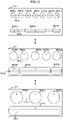
- the onboard device 10 causes the display region setting unit 123 to divide the display screen of the first display 21, and thus a plurality of (in the present embodiment, three) display regions 211 can be provided.
- FIG. 3 illustrates a display example of the three display regions 211 (a first display region 2111, a second display region 2112, and a third display region 2113) set on the display screen of the first display 21.
- the navigation screen, the air-conditioning screen, the audio screen, the radio screen, the application screen, the telephone screen, or the like can be allocated to each of the display regions 211.
- a plurality of operation reception buttons relating to different functions may be mixed and displayed on one display region 211.
- a pointer 212 is displayed on the display screen.
- the display region setting unit 123 dynamically changes a size of each of the display regions 211 on the display screen. Further, when a user touches off the pointer 212, the display region setting unit 123 confirms the size of each of the display regions 211.
- a division state of each of the display regions 211 provided on the display screen of the first display 21 is not limited to the display example in FIG. 3 , and is arbitrarily changed in accordance with an operation from a user.
- An operation of a user with respect to the pointer 212 on the display screen can be received not only from the touch panel 251 but also from the dial switch 252.
- arrangement regions 301a to 301f that are provided on each of the display regions 211 of the first display 21 and the display region 221 of the second display 22 ( FIG. 18 ) are described.
- the arrangement region 301 is simply referred to.
- FIG. 4 illustrates one example of the plurality of arrangement regions 301a to 301f provided on the display regions 211. Note that, although not illustrated, one or a plurality of arrangement regions 301 may also be provided on the display region 221 of the second display 22 similarly to each of the display regions 211 of the first display 21.
- the arrangement regions 301a to 301f are regions for arranging the display objects. Note that, in the drawings, positions of the arrangement regions 301a to 301f on the display regions 211 are indicated with broken lines, but the arrangement regions 301 are not actually displayed on the screen.
- the arrangement regions 301a, 301b, and 301c that extend in a transverse direction and the arrangement regions 301d, 301e, and 301f that extend in a vertical direction are provided on the display regions 211.
- a virtual two-dimensional (in embodiments outside the scope of the claimed invention) or three-dimensional (according to the claimed invention) coordination system independent from the x-y coordination system provided to the display screen of each of the first display 21 and the second display 22 is provided to the arrangement region 301.
- display of the display objects on each of the arrangement regions 301 can be changed easily.
- the arrangement region 301 has an area.
- the arrangement region 301 has a volume.
- the arrangement region 301 have axes (all of which are not illustrated) each having a direction (vector) extending from one end (start point) to the other end (end point) of the region (hereinafter, referred to as directional axes).
- the directional axes of the arrangement region 301 are not limited to linear lines parallel to the transverse direction or the vertical direction of the display regions 211, and may be linear lines in an oblique direction.
- the arrangement region 301 each have a rectangular shape, for example. However, in the drawing, in order to indicate the directions of the directional axes of the arrangement region 301, the arrangement regions 301 are illustrated as arrow regions.
- a length parallel to the directional axis of the arrangement region 301 is referred to as a directional-axis length
- a length in a direction orthogonal to the directional axis of the arrangement region 301 is referred to as a width.
- the arrangement region 301 are changed in directional-axis lengths and positions while maintaining directions of directional axes and widths.
- the directions of the directional axes may be changed.
- a maximum value for the directional-axis lengths of the arrangement region 301 may be set so as to prevent unlimited extension in accordance with the increase in size of the display regions 211.
- the arrangement regions 301 may be set to be visible or invisible as attribute information.
- a display object arranged in the arrangement region 301 set to be visible is displayed on the screen.
- a display object arranged in the arrangement region 301 set to be invisible is not displayed on the screen.
- the arrangement region 301 may be set to have priority relative to other arrangement regions 301 provided in the same display region 211. Note that, in the present embodiment, a higher value of priority indicates a higher priority order. Priority of the arrangement region 301 is set to to an initial value determined in advance by the priority setting unit 125. Priority of the arrangement region 301 may be changed in accordance with an operation from a user. Further, the priority setting unit 125 may learn a situation where change is made to priority, and may change priority dynamically in accordance with a learning result.
- the arrangement region 301 may be set whether or not to be a target of weeding-out in a case where at least a part thereof overlaps with other arrangement regions 301 provided in the same display region 211.
- the weeding-out indicates that attribute information relating to the arrangement region 301 with lower priority is changed from visible to invisible and a display object arranged in the arrangement region 301 having attribute information indicating invisible is removed from the screen.
- "weeding-out" indicates an action of changing attribute information relating to the arrangement region 301 or the display object from visible to invisible and removing the region or the object from the screen.
- the arrangement regions 301 having the directional axes parallel to each other can be set as "targets to be weeded out" as attribute information
- the arrangement regions 301 having the directional axes intersecting each other can be set as "not targets to be weeded out”.
- the shape of the arrangement region 301 is not limited to a rectangular shape, and may have other shapes.
- the shape of the arrangement region 301 may be a circular shape, a ring shape, and the like, and may be defined through use of a linear function.
- the width of the arrangement region 301 may be reduced extremely, and the shape of the arrangement region 301 may be defined as a substantial line.
- attribute information relating to the display objects 302 arranged in the arrangement region 301 is described.
- the display objects 302 arranged in the same arrangement region 301 and the display objects 302 arranged in the different arrangement regions 301 are displayed without being held in contact with each other or overlapping with each other, based on attribute information described below.
- FIG. 5 is a diagram for describing leading justification, center justification, and end justification that can be set as attribute information relating to the display objects 302a to 302f arranged in the arrangement region 301.
- the display object 302 is simply referred to.
- the display objects 302a to 302f arranged in the arrangement region 301 can be set with leading justification, center justification, or end justification.
- the leading justification is set for the display objects 302a and 302b.
- the display objects 302a and 302b are displayed closely from a start point side of the arrangement region 301 (from the left side in the drawing).
- the center justification is set for the display objects 302c to 302e.
- the display objects 302c to 302e are displayed closely at the center of the arrangement region 301.
- the end justification is set for the display objects 302f and 302g.
- the display objects 302f and 302g are displayed closely from an end point of the arrangement region 301 (from the right side in the drawing).
- the display objects 302 that are set with leading justification, center justification, or end justification as attribute information are displayed at an equal interval with the adjacent display objects 302.
- the plurality of display objects 302 arranged in the same arrangement region 301 are set to have different types of attribute information (leading justification, center justification, or end justification).
- the plurality of display objects 302 arranged in the same arrangement region 301 may be collectively set to the same attribute information (leading justification, center justification, or end justification).
- FIG. 6 is a diagram for describing upper alignment, center alignment, and lower alignment that can be set as attribute information for the display objects 302a to 302c arranged in the arrangement region 301.
- the display object 302 is simply referred to.
- upper alignment, center alignment, or lower alignment can be set for the display objects 302a to 302c arranged in the arrangement region 301.
- the upper alignment is set for the display object 302a.
- the display object 302a is displayed so as to have an upper end matching with an upper end of the arrangement region 301.
- the center alignment is set for the display object 302b.
- the display object 302b is displayed so as to have a center matching with a center of the width of the arrangement region 301.
- the lower alignment is set for the display object 302c.
- the display object 302c is displayed so as to have a lower end matching with a lower end of the arrangement region 301.
- the plurality of display objects 302 arranged in the same arrangement region 301 are set to have different types of attribute information (upper alignment, center alignment, or lower alignment). However, the plurality of display objects 302 arranged in the same arrangement region 301 may be collectively set to the same attribute information (upper alignment, center alignment, or lower alignment).
- FIG. 7 is a diagram for describing priority and visible or invisible that are set as attribute information with respect to display objects 3021 to 3027 arranged in the arrangement region 301.
- the display object 302 is simply referred to.
- the plurality of display objects 302 arranged in the arrangement region 301 can be set to have priority relative to other display objects 302 arranged in the same arrangement region 301.
- the plurality of display objects 302 arranged in the same arrangement region 301 may be set to have the same priority.
- numerals described for the display objects 302 are values indicating priority. In the following drawings, the same is applied.
- priority of the display objects 302 a higher value of priority indicates a higher priority order.
- the display objects 302 arranged in the arrangement region 301 are set to be visible or invisible.
- the display objects 3021 to 3027 each having a different priority are arranged in the arrangement region 301. Under a state illustrated in the uppermost row, attribute information relating to the display objects 3021 to 3027 is set as visible.
- the seven display objects 302 are displayed at a closer interval while maintaining the sizes as illustrated in the second row of FIG. 7 .
- the display object 3021 with the lowest priority among the seven display objects 302 is weeded out (attribute information is changed from visible to invisible).
- the six display objects 302 other than the weeded-out display object 3021 are displayed on the arrangement region 301.
- the display object 3022 with the lowest priority among the six display objects 302 is weeded out (attribute information is changed from visible to invisible).
- the five display objects 302 other than the weeded-out display objects 3021 and 3022 are displayed on the arrangement region 301.
- the directional-axis length of the arrangement region 301 is extended in accordance with size change (upsizing) of the display region 211 (not illustrated), display of the display objects 302 is changed from the lower row side to the upper row side of FIG. 7 . That is, the weeded-out display objects 302 (ones having attribute information changed to invisible) are restored and displayed on the arrangement region 301 in the priority order from a higher priority (attribute information is changed to visible).
- relative priority among the plurality of display objects 302 arranged in the same arrangement region 301 is set to an initial value in advance, and may be changed by the priority setting unit 125 in accordance with an operation from a user.
- the priority setting unit 125 may change priority in accordance with operation frequency from a user or set priority of the most recently operated object to the highest order.
- a priority of the three display objects 302 set to leading justification may be set to 2
- a priority of the two display objects 302 set to center justification may be set to 3
- a priority of the two display objects 302 set to end justification may be set to 1.
- Grouping may be performed accordingly.
- the plurality of display objects 302 arranged in the same arrangement region 301 are set to have the same priority and grouped.
- a group of the display objects 302 which are meaningless when the objects are not displayed at the same time (for example, a pair of buttons for raising and lowering a setting temperature for air-conditioning, a pair of buttons for turning up and down a sound volume for audio, and the like) can be weeded out or restored at the same time.
- the priority setting unit 125 may dynamically change priority in accordance with a vehicle situation (traveling speed and the like). For example, priority of the display objects 302 as information windows for displaying a character string is lowered during traveling.
- the priority setting unit 125 may learn a situation in which a user changes priority. At the time of a situation similar to the time when a user changes priority, the priority setting unit 125 may dynamically change priority in accordance with a learning result. With this, visibility of the display objects 302 for a user and operability of the display objects 302 being HMIs can be improved.
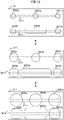
- FIG. 8 is a diagram for describing region dependent upsizing that is set as attribute information with respect to the display objects 302 arranged in the arrangement region 301.
- region dependent upsizing may be set for the display objects 302 arranged in the arrangement region 301.
- the display object 302 set to region dependent upsizing as attribute information is upsized and displayed in proportional to extension of the directional-axis length of the arrangement region 301 as illustrated in the lower row of the drawing.
- the display object 302 may be set to have a maximum size.
- FIG. 9 is a diagram for describing region dependent downsizing that is set as attribute information with respect to the display objects 302 arranged in the arrangement region 301.
- region dependent downsizing may be set for the display objects 302 arranged in the arrangement region 301.
- priority is not set for the three display objects 3021 to 3023, and only the display objects 3021 is set with region dependent downsizing as attribute information.
- the directional-axis length of the arrangement region 301 is reduced in accordance with downsizing of the display regions 211 (not illustrated) from the state illustrated in the upper row of FIG. 9 , to be smaller than a total length of the widths of the three display objects 3021 to 3023, the directional-axis length of the arrangement region 301 is reduced and displayed so that the width of the display objects 3021 that is set with region dependent downsizing among the three display objects 3021 to 3023 do not overlap with the display objects 3022 and 3023, as illustrated in the lower row of FIG. 9 . With this, the display objects 302 arranged in the arrangement region 301 can be displayed without being weeded-out while remaining the array order.
- FIG. 10 is a diagram for describing margin extension that is set as attribute information with respect to the display objects 3021 to 3023 arranged in the arrangement region 301.
- the display object 302 is simply referred to.
- margin extension is set for the display objects 302 arranged in the arrangement region 301.
- the display object 3021 with the lowest priority among the three display objects 3021 to 3023 is weeded-out (attribute information is changed to invisible), as illustrated in the lower row of FIG. 10 .
- a margin generated by weeding-out the display object 3021 is occupied by extending the width of the display object 3023 that is set with margin extension as attribute information. With this, a margin generated on the arrangement region 301 can be utilized efficiently.
- the directional-axis length of the arrangement region 301 is extended from the state illustrated in the lower row of FIG. 10 in accordance with size change (upsizing) of the display region 211 (not illustrated) so that the three display objects 3021 to 3023 can be displayed at an interval, specifically, the interval between the display objects 302 is the predetermined threshold value or more, display of the display object 3021 is restored on the arrangement region 301 (attribute information is changed to visible), as illustrated in the upper row of FIG. 10 .
- the display change of the display objects 302 in accordance with a situation indicates that, for example, display is performed in a downsizing manner so that a number of display objects 302 can be displayed at the same time while a vehicle is stopped or during automatic driving, and further indicates that, for example, the display objects 302 being HMIs are displayed in a upsizing manner when a traveling speed is high or a user is an aged person who is not good at detailed operation.
- FIG. 11 is a diagram for describing a situation that causes display change of the display objects 302.
- the driving environment information 501 and the individual adaptation information 502 are assumed.
- the driving environment information 501 includes an ADAS situation (indicating presence or absence of various types of advanced driving assist functions provided to a vehicle, a setting situation of activation or deactivation of such functions), road types (an expressway, a wide-area national route, a general road, a narrow city road, and the like), driving actions (a traveling speed, straight traveling, turning right or left, temporary stop, signal stop, and the like), cabin environment (a temperature, humidity, the number of passengers, and the like), and natural and social factors (seasons, weather, time range, traffic density, peripheral population density, and the like).
- ADAS situation indicating presence or absence of various types of advanced driving assist functions provided to a vehicle, a setting situation of activation or deactivation of such functions
- road types an expressway, a wide-area national route, a general road, a narrow city road, and the like
- driving actions a traveling speed, straight traveling, turning right or left, temporary stop, signal stop, and the like
- cabin environment a temperature, humidity, the number of passengers, and
- the individual adaptation information 502 includes individual characteristics (age, sex, driving history), operation capability (operation frequency, operation accuracy, and the like based on driving history and operation history), and biological information (a body temperature, a pulse, a respiration rate, a visual line, and the like) .
- the situation determination unit 127 determines whether to perform scaling of the display objects 302, based on at least one of the driving environment information 501 and the individual adaptation information 502. When scaling is performed, the situation determination unit 127 determines sizes of the display objects 302. Note that the sizes of the display objects 302 may be determined in a stepless manner in accordance with situation change, or may be determined by providing a plurality of steps. Further, the display control unit 124 follows the determination of the situation determination unit 127, and changes display of the display objects 302 on the display regions 211.
- FIG. 12 and FIG. 13 illustrate examples of display change of the display objects 302 in accordance with a situation.
- display of the display objects 302 on the display region 211 on the first display 21 is changed in a case where a traveling speed differs as a situation.
- the upper row of the drawing illustrates a low traveling speed (or stoppage).
- the middle row of the drawing illustrates an intermediate traveling speed.
- the lower row of the drawing illustrates a high traveling speed. It is assumed that the size of the display region 211 illustrated in the upper row, the middle row, and the lower row of the drawing is not changed.
- the sizes of the display objects 302 are changed by three steps including large, middle, and small sizes in accordance with a traveling speed.
- the sizes of the display objects 302 may be changed by two steps, four steps or more, or more finely in a stepless manner.
- the display region 211 is provided with the arrangement region 301a and the arrangement region 301b, the seven display objects 3021a to 3027a having different priorities are arranged in the arrangement region 301a, and the three display objects 3021b to 3023b having different priorities are arranged in the arrangement region 301b.
- the display object 3022b is set with leading justification
- the display object 3023b is set with center justification
- the display object 3021b is set with end justification as attribute information.
- the display objects 3021a to 3027a and the display objects 3021b to 3023b are set with situation scaling, as attribute information.
- the display objects 3021a to 3027a and the display objects 3021b to 3023b are upsized to a middle size because situation scaling as attribute information is set.
- the seven display objects 3021a to 3027a upsized to a middle size cannot be displayed at an interval.
- the two display objects 3021a and 3022a with a lower priority are weeded out, and the remaining five display objects 3023a to 3027a are displayed in a middle size.
- the three display objects 3021b to 3023b upsized to a middle size are displayed.
- the display objects 3021a to 3027a and the display objects 3021b to 3023b are upsized to a large size.
- the seven display objects 3021a to 3027a upsized to a large size cannot be displayed at an interval.
- the four display objects 3021a to 3024a with a lower priority are weeded out, and the three display objects 3025a to 3027a upsized to a large size are displayed.
- the two display objects 3021b and 3022b with a lower priority are weeded out, and the display object 3023b upsized to a large size is displayed.
- each of the display objects 302 is reduced in size, and display thereof is restored.
- the widths of the display objects 302 may be reduced to a predetermined minimum size in the priority order from a lower priority side.
- the display region 211 is provided with the arrangement region 301a and the arrangement region 301b, the three display objects 3021a to 3023a set to have the same priority are arranged in the arrangement region 301a, and the three display objects 3021b to 3023b set to have the same priority are arranged in the arrangement region 301b.
- the display objects 3022a and 3022b are set with leading justification
- the display objects 3023a and 3023b are set with center justification
- the display objects 3021a and 3021b are set with end justification as attribute information.
- attribute information situation scaling is set for the display objects 3021a to 3023a and the display objects 3021b to 3023b.
- region dependent downsizing is set for the display object 3023b.
- the display objects 3021a to 3023a and the display objects 3021b to 3023b are upsized to have a middle size because situation scaling as attribute information is set.
- the three display objects 3021a to 3023a upsized to a middle size on the arrangement region 301a do not overlap with each other, and hence the three display objects 3021a to 3023a upsized to a middle size are displayed on the arrangement region 301a.
- the three display objects 3021b to 3023b upsized to a middle size are displayed.
- the display objects 3021a to 3023a and the display objects 3021b to 3023b are upsized to a large size. Also in this case, the positions of the three display objects 3021a to 3023a upsized to a large size on the arrangement region 301a do not overlap with each other, and hence the three display objects 3021a to 3023a upsized to a large size are displayed on the arrangement region 301a. Meanwhile, the three display objects 3021b to 3023b upsized to a large size cannot be displayed at an interval on the arrangement region 301b.
- the display object 3023b set to region dependent downsizing as attribute information is displayed by reducing a width in a large size, and the display objects 3021b and 3022b that are not set to region dependent downsizing are upsized to a large size and displayed.
- FIG. 14 is a diagram for describing a scaling method for the display region 211 and the display object 302.
- FIG. 14A illustrates the field angle changing method
- FIG. 14B illustrates the camera distance changing method.
- a virtual camera C is fixed in front of the display region 211 for displaying the display object 302, at a position away therefrom by a distance L, and a field angle of the camera C is changed.
- scaling of the display object 302 is performed.
- the field angle of the camera C is narrowed.
- the field angle of the camera C is widened.
- the field angle changing method for example, an effect of performing zooming-in through use of a telephoto lens and zooming-out through use of a wide angle lens can be obtained.
- distortion of the display object 302 due to perspective conversion can be suppressed as compared to the camera distance changing method.
- the virtual camera C is arranged in front of the display region 211 for displaying the display object 302, and the distance L between the display regions 211 and the camera C is changed. In this manner, scaling of the display object 302 is performed. Specifically, when the display object 302 is upsized, the camera C is brought closer to the display region 211 so as to reduce the distance L. When the display object 302 is downsized, the camera C is away from the display region 211 so as to increase the distance L. In the case of the camera distance changing method, for example, an effect of giving a sense of actually seeing the display object 302 while being close to or away from the display object 302 can be obtained.
- distortion of the display object 302 due to perspective conversion is conspicuous as compared to the field angle changing method.
- the distortion can express a three-dimensional effect more.
- the screen size of the first display 21 is small, even when one display region 211 is provided without dividing the display screen, let alone when the display screen is divided into plurality of regions to obtain the plurality of display regions 211, visibility and operability of the display objects 302 may be degraded in some cases.
- a maximum display region 211M which is determined in accordance with the screen size of the first display 21, is controlled.
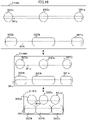
- FIG. 15 illustrates display examples of the display objects 302 on the maximum display regions 211M having different screen sizes on the first display 21.
- the upper row of the drawing illustrates a case of a large screen (for example, 15 inches)
- the middle row of the drawing illustrates a case of a middle screen (for example, 13 inches)
- the lower row of the drawing illustrates a case of a small screen (for example, 10 inches).
- the maximum display regions 211ML, 211MM, and 211MS are each provided with the arrangement region 301a and the arrangement region 301b.
- the seven display objects 3021a to 3027a having different priorities are arranged in the arrangement region 301a, and the three display objects 3021b to 3023b having different priorities are arranged in the arrangement region 301b.
- the display object 3022b is set with leading justification
- the display object 3023b is set with center justification
- the display object 3021b is set with end justification as attribute information.
- the directional-axis lengths of the arrangement region 301a and the arrangement region 301b are long enough to display all the display objects 302 arranged in the regions.
- the directional-axis length of the arrangement region 301a is reduced, and not all the seven display objects 3021a to 3027a can be displayed as compared to the case of the large screen illustrated in the upper row of FIG. 15 .
- the two display objects 3021a and 3022a with a lower priority are weeded out, and the remaining five display objects 3023a to 3027a are displayed.
- the three display objects 3021b to 3023b on the arrangement region 301b are displayed at a reduced interval.
- the directional-axis length of the arrangement region 301a is further reduced as compared to the middle screen illustrated in the middle row of FIG. 15 , and not all the seven display objects 3021a to 3027a can be displayed.
- the four display objects 3021a and 3024a with a lower priority are weeded out, and the remaining three display objects 3025a to 3027a are displayed.
- the two display objects 3021b and 3022b with a lower priority are weeded out, and the remaining display object 3023b is displayed.
- the display objects 302 can be weeded out in accordance with priority, and display can be performed without changing the size and layout of the display objects 302. Thus, operability on the first display 21 can be maintained.
- the width of the display objects 302 may be reduced in the priority order from a low degree side.
- FIG. 16 illustrates other display examples of the display objects 302 on the maximum display regions 211M having different screen sizes on the first display 21.
- the upper row of the drawing illustrates a case of a large screen (for example, 15 inches)
- the middle row of the drawing illustrates a case of a middle screen (for example, 13 inches)
- the lower row of the drawing illustrates a case of a small screen (for example, 10 inches).
- the maximum display regions 211ML, 211MM, and 211MS are each provided with the arrangement region 301a and the arrangement region 301b, the three display objects 3021a to 3023a set to have the same priority are arranged in the arrangement region 301a, and the three display objects 3021b to 3023b set to have the same priority are arranged in the arrangement region 301b.
- the display objects 3022a and 3022b are set with leading justification
- the display objects 3023a and 3023b are set with center justification
- the display objects 3021a and 3021b are set with end justification as attribute information.
- region dependent downsizing is set for the display object 3023b.
- the directional-axis lengths of the arrangement region 301a and the arrangement region 301b are long enough to display all the display objects 302 arranged in the regions.
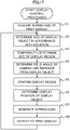
- FIG. 17 is a flowchart illustrating one example of the display control processing performed by the onboard device 10.
- the display control processing is started after activation of the onboard device 10, and is continuously executed until an operation of the onboard device 10 is completed.
- the display region setting unit 123 acquires the screen size of the first display 21, and specifies the maximum display region 211M in accordance with the screen size (Step S1). Note that the screen size of the first display 21 may be acquired directly from the first display 21, or hardware information stored in the storage unit 130 may be referred to.
- the situation determination unit 127 determines whether to perform scaling of the display objects in accordance with a situation of a vehicle or a driver (a user) based on the driving environment information 501 and the individual adaptation information 502, and determines sizes of the display objects 302 in a case where scaling is performed (Step S2).
- the display region setting unit 123 temporarily determines a size of the display region 211 based on a correlation between the maximum display region 211M provided to the first display 21, which is specified in Step S1 and the display objects 302 determines in Step S2 (Step S3).
- the display control unit 124 determines the field angle of the virtual camera C ( FIG. 14 ) and the distance L between the camera C and the display objects 302 so as to achieve the size of the display region 211 determined in Step S3 (Step S4).
- the display region setting unit 123 corrects the display region 211 that is temporarily determined, as appropriate, and confirms the size of the display region 211 (Step S5) .
- the display control unit 124 determines display positions of the display objects 302 on the display region 211, based on attribute information such as priority set with respect to the display objects 302 (Step S6).
- the display control unit 124 generates image data for causing the first display 21 to display the display region 211 in which the display objects 302 are arranged (Step S7).
- the display control unit 124 outputs the generated image data to the first display 21 (Step S8).
- the display region 211 with the display objects 302 subjected to scaling in accordance with a situation is displayed.
- the processing returns to Step S3, and is repeated from Step S3 to Step S8.
- the sizes of the display objects 302 on the display region 211 may be dynamically changed in accordance with a situation. Therefore, screen display excellent in visibility and operability for a user can be achieved.
- the display control processing performed by the onboard device 10, which is described above, can be executed without depending on an aspect ratio or a resolution of the first display 21.
- the arrangement region 301 is changed in a directional-axis length and a position while maintaining the direction of the directional axis and width.
- the arrangement region 301 may be modified in accordance with situation change. Specifically, modification may be made, in embodiments outside the scope of the claimed invention, in a two-dimensional coordination system of the arrangement region 301, which is parallel to a coordination system of the display screen and independent from the coordination system of the display screen, or modification may be made, according to the claimed invention, in a coordination system in three or more dimension of the arrangement region 301, which is independent from the coordination system of the display screen.
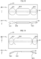
- FIG. 18 illustrates a modification example being a state before modification in accordance with situation change of the arrangement region 301 provided to the display region 221 of the second display 22.
- FIG. 19 to FIG. 22 illustrate the modification example being a state after modification in accordance with situation change of the arrangement region 301 provided to the display region 221 of the second display 22.
- a virtual three-dimensional xyz coordination system as illustrated is assumed with respect to the arrangement region 301. Further, on the display region 221 of the second display 22, a state in which the arrangement region 301 having the virtual three-dimensional xyz coordination system is subjected to perspective conversion into the display region 221 having a two-dimensional x-y coordination system is displayed.
- the arrangement region 301 is in a state parallel to the display screen (xy plane) before modification. Further, when a situation is changed, in the modification example illustrated in FIG. 19 , the width of the display object 3022 is upsized in order to increase an information amount of the display object 3022 arranged at the center of the arrangement region 301, and both ends of the arrangement region 301 on which the display objects 3021 and 3023 other than the upsized display object 3022 are arranged are in a folded state in a direction orthogonal to the display screen (xy plane) (+z direction). Further, the display objects 3021 and 3023 arranged in the folded parts of the arrangement region 301 are displayed in an obliquely-viewed shape on the display region 221. Meanwhile, the display object 3022 arranged at the non-folded portion of the arrangement region 301 is displayed on the display region 221 while maintaining a shape viewed from the front and being upsized in the lateral direction (y direction).
- situation change that modifies the arrangement region 301 is not limited to switching to automatic driving.
- the arrangement region 301 may be modified in accordance with change in traveling speed.
- the modification example of the arrangement region 301 is not limited to the example illustrated in FIG. 19 .
- only one end of the both ends of the arrangement region 301 may be folded.
- an end of the arrangement region 301 may be folded in a -z direction.
- an end of the arrangement region 301 may be folded in the +z direction or the -z direction at approximately 90 degrees so that side surfaces of the display objects 3021 and 3023 are visually recognized.
- the substantially same information as the information displayed on the front surface may be displayed in a different form.
- the display objects 3021 and 3023 are a speed meter and a tachometer
- an analog meter indicating a speed or the like with a rotating pointer may be displayed on each of the front surfaces
- a digital meter indicating a speed or the like with a numeral value, a bar chart, or the like may be displayed on each of the side surfaces.
- the display objects 3021 and 3023 may not be provided with a thickness in the z direction so that the display objects 3021 and 3023 are substantially invisible.
- the arrangement region 301 may be modified by being folded to have depth in the z direction.
- FIG. 21 illustrates a modification example in which the arrangement region 301 is folded in a Z-like shape with depth in the z direction.
- the display objects 3021 to 3023 are displayed on the display region 221 under a state of overlapping in the z direction.
- the display objects 3022 and 3023 are partially hidden, but the display objects 3021 to 3023 can be displayed in the original size. Note that modification may be made so that the three liner lines indicating the arrangement region 301 after modification are parallel to one another.
- FIG. 22 illustrates a modification example in which the arrangement region 301 is folded in a U-like shape in the xy plane parallel to the display region 221.
- the display objects 3021 to 3023 displayed in one row are displayed in two separate rows.
- modification of the arrangement region 301 in accordance with situation change may be performed not only on the display region 221 of the second display 22 but also on the display region 211 of the first display 21.
- modification of the arrangement region 301 illustrated in FIG. 19 is applied to the display example of FIG. 12 , and the sizes of the display objects 3021b to 3023b are upsized as the modification example in the lower row of FIG. 12 .
- the arrangement region 301b may be folded so that the display objects are displayed in an obliquely-viewed shape in the priority order from a lower priority side.
- both the ends of the arrangement region 301b may be folded to display the display objects 3021b and 3022b in an obliquely-viewed shape, and the display object 3023b upsized to a large size may be displayed in a shape viewed from the front.
- the present invention is applicable to a case where, for example, a screen is obtained with a projector through screen projection in addition to a case where a screen is displayed on the displays (the first display 21 and the second display 22) as in the present embodiment.
- the present invention is not limited to the embodiment described above, and includes various modification examples.
- the embodiments described above are described in detail for the sake of easier understanding of the present invention, and the present invention is not necessarily limited to including all the configurations described herein. It is possible to replace a part of a configuration of one embodiment with a configuration of another embodiment. It is also possible to add a configuration of one embodiment to a configuration of another embodiment. Another configuration can be added to, deleted from, and replaced with a part of a configuration of each embodiment.
- a part of or an entirety of the configurations, functions, processing units, processing means, and the like described above may be implemented by hardware by designing those with, for example, integrated circuits or the like.
- Each of the configurations, functions and the like described above may be implemented by software by a processor that interprets and executes programs for achieving each function.
- Information for achieving each of the functions, such as a program, a determination table, and a file may be placed in a storage device such as a memory, an HDD, and an SSD, and a recording medium such as an IC card, an SD card, and a DVD. Illustrations of control lines and information lines are those considered to be necessary for the sake of description, and not necessarily include all the control lines and information lines necessary as a product. In actuality, it may be considered that almost all the configurations are connected to each other.
- the present invention may be provided in various forms such as a computer-readable program.
Landscapes
- Engineering & Computer Science (AREA)
- Theoretical Computer Science (AREA)
- General Engineering & Computer Science (AREA)
- Physics & Mathematics (AREA)
- General Physics & Mathematics (AREA)
- Mechanical Engineering (AREA)
- Human Computer Interaction (AREA)
- Chemical & Material Sciences (AREA)
- Combustion & Propulsion (AREA)
- Transportation (AREA)
- Computer Hardware Design (AREA)
- User Interface Of Digital Computer (AREA)
- Controls And Circuits For Display Device (AREA)
Description
- The present invention relates to a display control device and a display control method.
- As an invention relating to information display on a display, for example,
JP 2015-87861 A PTL 1 describes that "the display control unit has a split display mode in which a first display region included in the display region is divided into a plurality of split regions and display of each of the plurality of split regions is independently controlled. In the split display mode, the display unit is caused to display one operation target image that enables setting for each of the plurality of split regions". - PTL 1:
JP 2015-87861 A - The
document EP 3 208 132 A2 discloses a display control device according to the preamble ofclaim 1. Further related art is disclosed inUS 9 469 195 B1 - As described in
PTL 1, it has hitherto been possible to divide a display region into a plurality of split regions and control display of each split region independently. Specifically, when a size of the split region is changed, it is possible to simply downsize or upsize a display object such as an icon displayed on the split region, change a layout in a stepwise manner, perform trimming partially, or hide the display object. - However, display change of the display object described above when the size of the split region is changed is not sufficiently in conformity with dynamic change in size of the split region. Thus, it is difficult to say that optimal display of the display object is provided.
- When the display object is a human machine interface (HMI) such as an operation button displayed on the display on which a touch panel is layered, not only visibility but also operability are to be prevented from degrading. Thus, a display method of the display object can be changed preferably in accordance with environment and a situation of a user as well as the size of the split region.
- The present invention has been made in view of such circumstances, and has an object to enable display of a display object to be changed more appropriately.
- The present application includes a plurality of solutions to at least a part of the problems described above. One example of the solutions is as follows.
- In order to solve the above-mentioned problem, the present invention provides a display control device and a display control method as defined in the appended independent claims.
- According to one aspect of the present invention, display of the display object can be changed more appropriately.
- Note that problems, configurations, and effects other than those described above will become apparent in the following description of the embodiments.
-
-
FIG. 1 is a block diagram illustrating a configuration example of an onboard device according to one embodiment of the present invention. -
FIG. 2 is a diagram illustrating one example of a function block of the onboard device. -
FIG. 3 is a diagram illustrating an example of a display region obtained by dividing a display screen of a first display into three. -
FIG. 4 is a diagram illustrating an example of an arrangement region that is set as a display region. -
FIG. 5 is a diagram for describing attribute information relating to display objects (leading justification, center justification, or end justification). -
FIG. 6 is a diagram for describing attribute information relating to the display objects (upper alignment, center alignment, or lower alignment). -
FIG. 7 is a diagram for describing attribute information relating to the display objects (priority, visible, or invisible). -
FIG. 8 is a diagram for describing attribute information relating to the display objects (region dependent upsizing). -
FIG. 9 is a diagram for describing attribute information relating to the display objects (region dependent downsizing). -
FIG. 10 is a diagram for describing attribute information relating to the display objects (margin extension). -
FIG. 11 is a diagram for describing a situation that causes display change of the display objects. -
FIG. 12 is a diagram illustrating examples of display change of the display objects in accordance with a situation. -
FIG. 13 is a diagram illustrating another examples of display change of the display objects in accordance with a situation. -
FIG. 14A and FIG. 14B are diagrams for illustrating scaling methods.FIG. 14A is a diagram illustrating a field angle changing method, andFIG. 14B is a diagram illustrating a camera distance changing method. -
FIG. 15 is a diagram illustrating display examples of the display objects in maximum display regions in different screen sizes on the first display. -
FIG. 16 is a diagram illustrating other display examples of the display objects in maximum display regions in different screen sizes on the first display. -
FIG. 17 is a flowchart illustrating one example of display control processing performed by anonboard device 10. -
FIG. 18 is a diagram illustrating a state before modification of the arrangement region in accordance with change of a situation. -
FIG. 19 is a diagram illustrating a state after modification of the arrangement region in accordance with change of a situation. -
FIG. 20 is a diagram illustrating a state after modification of the arrangement region in accordance with change of a situation. -
FIG. 21 is a diagram illustrating a state after modification of the arrangement region in accordance with change of a situation. -
FIG. 22 is a diagram illustrating a state after modification of the arrangement region in accordance with change of a situation. - With reference to the drawings, an embodiment of the present invention is described below. Note that, in all the drawings for describing the embodiment, in principle, the identical members are denoted with the identical reference symbols, and repeated description therefor is omitted as appropriate. In the following embodiment, it goes without saying that constituent elements therein (including element steps and the like) are not necessarily essential unless otherwise particularly stated or incontrovertibly considered as essentials in principle. When the expressions "constituted of A", "being formed of A", "including A", and "comprising A" are given, it goes without saying that the expressions are not intended to exclude elements other than A unless A otherwise is clearly stated as the only element. Similarly, in the following embodiment, when shapes, positional relationships, and the like of the constituent elements and the like are referred to, substantially approximate or similar shapes and the like are included unless otherwise particularly stated or incontrovertibly considered to be different in principle or the like.
- The
onboard device 10 according to one embodiment of the present invention is described below. Theonboard device 10 corresponds to a display control device according to the present invention. -
FIG. 1 illustrates a configuration example of theonboard device 10 according to one embodiment of the present invention. Theonboard device 10 can be implemented with an onboard navigation device having a navigation function, for example. Thus, theonboard device 10 is, for example, a box-like device including afirst display 21 on a front surface, and is housed in a console panel inside a vehicle. Theonboard device 10 may include a mounting tool (bracket) to be mounted to the console panel, and may be mounted, for example, above the console panel inside the vehicle by the mounting tool. - Here, the navigation function refers to a function that a navigation device usually has such as displaying map information, searching for a recommended route and navigating from a departure place (or a current place) to a target place, and displaying traffic information. Note that the
onboard device 10 is not limited to a dedicated navigation device, and may be, for example, a smartphone, a tablet terminal device, and a personal data assistance (PDA). In this case, the navigation function is provided by an application installed in those devices or a server device to which those devices can connect. - In addition to a navigation screen relating to the navigation function, the
onboard device 10 can display an air-conditioning screen for setting a temperature, a wind direction, an air flow rate, and the like of an air-conditioner, an audio screen for selecting songs and setting a sound volume and the like of audio, a radio screen for selecting radio stations and the like, a screen of an application executed by a wirelessly connected smartphone (hereinafter, referred to as an application screen), a telephone screen for outgoing and incoming calls, a vehicle information screen for displaying various types of information and performing setting relating to a vehicle, and the like. - The
onboard device 10 includes anarithmetic processing device 11, thefirst display 21, asecond display 22, astorage device 23, a voice input/output device 24, aninput device 25, and a read only memory (ROM)device 26. - Further, the
onboard device 10 includes avehicle speed sensor 27, agyro sensor 28, asatellite positioning device 29, an FM multiplexbroadcasting reception device 30, and abeacon reception device 31. - Moreover, the
onboard device 10 further includes a plurality of communication I/Fs (all of them are not illustrated) such as an I/F for communicating with an external electronic device (for example, a smartphone), an I/F for communicating with a network inside a vehicle such as a controller area network (CAN), an I/F for communicating with another device inside the vehicle such as an electronic control unit (ECU) and advanced driver assistance systems (ADASs), and an I/F for communicating with a vital sensor that detects biological information of a driver. - The
arithmetic processing device 11 is a central unit that performs various types of processing of theonboard device 10. As a navigation function, thearithmetic processing device 11 detects a current place through use of information output from various sensors such as thevehicle speed sensor 27 and thesatellite positioning device 29, for example. Based on the acquired current place information, thearithmetic processing device 11 reads map information required for display from thestorage device 23 and theROM device 26. Thearithmetic processing device 11 develops the read map information into graphics, overlaps a mark indicating the current place thereon, to generate and output an image signal to be displayed on thefirst display 21. Thearithmetic processing device 11 calculates a recommended route connecting from a departure place and a target place that are instructed from a user (a driver or a passenger), through use of map information and the like stored in thestorage device 23 or theROM device 26. Thearithmetic processing device 11 navigates along the route by outputting a predetermined signal to aspeaker 242 and thefirst display 21. - The
arithmetic processing device 11 acquires hardware information (a screen size, an aspect ratio, a resolution, and the like) from thefirst display 21 and thesecond display 22,respectively. Thearithmetic processing device 11 sets a plurality of display regions on a display screen of thefirst display 21, and allocates various screens (the navigation screen, the air-conditioning screen, the audio screen, the application screen, the telephone screen, the vehicle information screen, and the like) to the display regions. Further, thearithmetic processing device 11 changes sizes of the display regions in accordance with an operation from a user. Moreover, thearithmetic processing device 11 further displays predetermined display objects (icons, thumbnail images, HMIs such as operation buttons, information display windows, and the like) independently in each display region in a predetermined display form. Further, thearithmetic processing device 11 displays predetermined display objects (a speed meter, a tachometer, and information windows) on thesecond display 22 in a predetermined shape. - The
arithmetic processing device 11 as described above includes a central processing unit (CPU) 111 that executes various types of processing for performing arithmetic operations and controlling the devices, a random access memory (RAM) 112 that temporarily stores map information, arithmetic data, and the like having been read from a memory device such as thestorage device 23 and aROM 113, theROM 113 that stores a boot program and the like executed by theCPU 111, an interface (I/F) 114 for connecting various types of hardware to thearithmetic processing device 11, and abus 115 that connects those components to each other. - The
first display 21 is installed at the center of the console panel provided on the front surface inside the vehicle, for example. Thefirst display 21 is a unit that displays graphics information. Thefirst display 21 is formed of a liquid crystal display, an organic EL display, or the like, for example. Note that, as described later, a transparent touch panel 251 is layered on thefirst display 21. Therefore, a user can perform a touch operation on (the touch panel 251 layered on) thefirst display 21. However, an operation on thefirst display 21 may also be performed through use of adial switch 252. - The
second display 22 is installed in an instrument panel provided in front of a driver's seat, for example. For example, in a case of a vehicle in which a steering wheel is installed on a left side as in a US specification vehicle, thesecond display 22 is set on a left side to thefirst display 21 installed at the center of the console panel as seen from a user. - For example, a display that displays images such as a speed meter indicating a speed of a vehicle, a tachometer indicating the number of rotation of an engine, and the like may be applied as the
second display 22, or thesecond display 22 dedicated to theonboard device 10 may be provided. Thesecond display 22 is a unit that displays graphics information. Thesecond display 22 is formed of a liquid crystal display, an organic EL display, or the like, for example. - The
storage device 23 is formed of a storage medium capable of reading and writing information, such as a hard disk drive (HDD) and a non-volatile memory card. Various pieces of information used by thearithmetic processing device 11 are stored in thestorage device 23, for example. - The voice input/
output device 24 includes amicrophone 241 as a voice input device and thespeaker 242 as a voice output device. Themicrophone 241 collects sound such as voice that is made by a driver or a passenger (user utterance) outside theonboard device 10. Thespeaker 242 outputs voice or sound such as route guidance and the like for a driver and the like, which is generated by thearithmetic processing device 11. - The
input device 25 is a device that receives an instruction input from a user. Theinput device 25 includes the touch panel 251, thedial switch 252, a scroll key being another hard switch, and the like (not illustrated). Theinput device 25 outputs information in accordance with an operation of the keys and switches to another device such as thearithmetic processing device 11. - The touch panel 251 is formed of a transparent material, and is layered on the display screen of the
first display 21. The touch panel 251 detects a touch operation by a finger of a user or a touch pen (touch-on (contact), dragging (move in a contact state), and touch-off (release of contact)). Thus, while visually recognizing the display screen of thefirst display 21, a user can input various operations by touching the display screen (actually, the touch panel 251). A position of a touch operation of a user is specified based on an x-y coordination set on the touch panel 251, for example. The touch panel 251 is formed of input detection elements of a capacitive sensing type, for example. - The
ROM device 26 is formed of at least a readable storage medium such as a ROM exemplified by a compact disk (CD)-ROM and a digital versatile disk (DVD)-ROM, an integrated circuit (IC) card and the like. Map information, moving image data, voice or sound data, and the like are stored in the storage medium, for example. - The
vehicle speed sensor 27 is a sensor that acquires a value used for calculation of a vehicle speed. Thegyro sensor 28 is a sensor that is formed of an optical fiber gyroscope, an oscillation gyroscope, or the like, and detects angular velocity of rotation of a moving body (vehicle). - The
satellite positioning device 29 can measure a current place, a traveling speed, and a traveling direction of a moving body by receiving signals from artificial satellites exemplified by GPS satellites and measuring distances between the moving body and the artificial satellites and rates of change of the distances with respect to three or more artificial satellites. Those devices are used for thearithmetic processing device 11 in order to detect a current place of a vehicle to which theonboard device 10 is mounted. - The FM multiplex
broadcasting reception device 30 receives FM multiplex broadcasting that is transmitted through use of an FM broadcasting wave. FM multiplex broadcasting includes an outline of current traffic information relating to vehicle-information-and-communication-system (VICS) information, regulation information, service area/parking area (SA/PA) information, parking lot information, weather information, character information as general FM multiplex information, and the like. - The
beacon reception device 31 receives an outline of current traffic information relating to VICS information, regulation information, service area/parking area (SA/PA) information, parking lot information, weather information, an emergency alert, and the like. Thebeacon reception device 31 may be, for example, an optical beacon that performs communication through light or a radio wave beacon that performs communication through a radio wave. - Next,
FIG. 2 illustrates a configuration example of a function block included in theonboard device 10. - The
onboard device 10 includes acontrol unit 120 and astorage unit 130. - The
control unit 120 includes function blocks being aninput reception unit 121, an operation detection unit 122, a displayregion setting unit 123, adisplay control unit 124, apriority setting unit 125, afunction processing unit 126, and asituation determination unit 127. - The
input reception unit 121 receives an instruction and an input of information from a user through thedial switch 252 of theinput device 25 or other hard switches. For example, theinput reception unit 121 receives setting of a departure place and a target place, a search instruction for a recommended route, and the like through theinput device 25 from a user. - The operation detection unit 122 detects a touch operation made by a user with respect to the touch panel 251 of the
input device 25. Specifically, the operation detection unit 122 detects touch-on, dragging, and touch-off with respect to the touch panel 251. The operation detection unit 122 specifies an x-y coordination on the touch panel 251 subjected to a touch operation. - The operation detection unit 122 can also detect a plurality of (for example, two) touches on the touch panel 251 within a predetermined time period (for example, 0.5 seconds), and can specify an x-y coordination on the touch panel 251 which indicates each touch position.
- When detecting a touch operation (including touch-off), the operation detection unit 122 notifies the display
region setting unit 123 and thefunction processing unit 126 of a type and an x-y coordination of the touch operation. - The display
region setting unit 123 acquires hardware information (a screen size, an aspect ratio, a resolution, and the like) from thefirst display 21 and thesecond display 22,respcttively, and stores the information in thestorage unit 130. Note that the hardware information relating to thefirst display 21 and thesecond display 22 may be stored in thestorage unit 130 in advance at the time of shipping. The displayregion setting unit 123 sets a display region on the display screen of thefirst display 21. Specifically, based on the notification from the operation detection unit 122, the displayregion setting unit 123 sets a division state (position and size) of a plurality of display regions obtained by dividing the display screen of thefirst display 21. Note that, in the present embodiment, a case where the display screen is divided into three is described, but the number of divisions may be two or four or more. The displayregion setting unit 123 may not divide the display screen, and display only one display region on the display screen. - The
display control unit 124 controls setting of an arrangement region for each of the display regions of thefirst display 21 and the display region of thesecond display 22 and display of display objects. Thedisplay control unit 124 changes a size and a position of the arrangement region, attribute information, and the like in accordance with the change in size of the display region. Thedisplay control unit 124 changes positions of the display objects arranged in the arrangement region and attribute information in accordance with the change in size of the arrangement region. - The
priority setting unit 125 sets priority with respect to the arrangement region provided in the display region and the display objects arranged in the arrangement region. Thepriority setting unit 125 can set an initial value determined in advance as priority with respect to the arrangement region and the display objects, and can change priority in accordance with an input from a user afterward. - The
priority setting unit 125 may learn a situation where change is made to priority, and may change priority dynamically based on a learning result. Here, the situation indicates driving environment information 501 (FIG. 11 ) that can be acquired by theonboard device 10, such as a current place, a traveling speed, whether automatic driving is performed, types of roads during traveling, a traffic condition, a temperature, weather, time range, and the like with respect to a vehicle to which theonboard device 10 is mounted. Specifically, for example, at a predetermined time range, an arrangement region or a display object corresponding to an air-conditioning function may have high in priority. - Note that, when priority is changed, the arrangement region and the display of the display objects based on priority may be dynamically changed. The
priority setting unit 125 updatesarrangement region information 133 based on priority set among the arrangement regions, and updates displayobject information 134 based on priority set among the display objects. - The
function processing unit 126 executes processing for achieving predetermined functions in accordance with a touch operation from a user with respect to a display object as an HMI displayed on the display region of thefirst display 21. The functions referred herein include, for example, a navigation function, an air-conditioning function, music play, selection of radio stations, outgoing and incoming telephone calls, and the like. - Based on the driving environment information 501 (
FIG. 11 ) that can be acquired from various sensors, an ECU, an ADAS, and the like mounted on a vehicle and individual adaptation information 502 (FIG. 11 ) that is input from a user or detected with a vital sensor, thesituation determination unit 127 determines whether to perform scaling of a display object in accordance with a situation of a vehicle or a driver (user). Further, when scaling of the display object is performed in accordance with the situation, thesituation determination unit 127 determines a size of the display object. - The
storage unit 130 stores predetermined information. Thestorage unit 130 is implemented with thestorage device 23, theROM device 26, and theROM 113. Various types of information such asmap information 131,display region information 132, thearrangement region information 133, thedisplay object information 134, and others are stored in thestorage unit 130. - Information on land forms, roads, and the like that are used for the navigation function is recorded as the
map information 131. - Division states of the display regions provided on the display screen of the
first display 21 are recorded as thedisplay region information 132. A shape, a size, a position, and attribute information (including priority) of the arrangement region provided in each of the display regions of thefirst display 21 and thesecond display 22 are recorded as thearrangement region information 133. Image data and attribute information (including priority) of the displayed objects displayed on the display regions are recorded as thedisplay object information 134. - Note that the function blocks of the
onboard device 10, which are theinput reception unit 121, the operation detection unit 122, the display region setting unit, thedisplay control unit 124, thepriority setting unit 125, thefunction processing unit 126, and thesituation determination unit 127, are implemented by theCPU 111 executing predetermined programs. The programs are stored in theROM 113 of theonboard device 10 or thestorage device 23, and are loaded on theRAM 112 at the time of execution and executed by theCPU 111. - Each functional block illustrated in
FIG. 2 is classified according to its main processing contents, for the sake of easier understanding of the functions of theonboard device 10 implemented in the present embodiment. Therefore, how each function is classified and referred to does not limit the present invention. Each configuration of theonboard device 10 can be classified into more components, according to the processing contents. Each configuration can be classified so that one component executes more processing. - All or a part of the function blocks may be constituted by hardware (an integrated circuit such as an ASIC, or the like) implemented in a computer. Processing of each of the function blocks may be executed by one piece of hardware, or may be executed by a plurality of pieces of hardware.
- Next, display regions set on the display screen of the
first display 21 are described. As described above, theonboard device 10 causes the displayregion setting unit 123 to divide the display screen of thefirst display 21, and thus a plurality of (in the present embodiment, three)display regions 211 can be provided. -
FIG. 3 illustrates a display example of the three display regions 211 (afirst display region 2111, asecond display region 2112, and a third display region 2113) set on the display screen of thefirst display 21. - For example, the navigation screen, the air-conditioning screen, the audio screen, the radio screen, the application screen, the telephone screen, or the like can be allocated to each of the
display regions 211. A plurality of operation reception buttons relating to different functions (for example, air-conditioning, audio, radio, and telephone) may be mixed and displayed on onedisplay region 211. - When the display screen of the
first display 21 is divided into the plurality ofdisplay regions 211, apointer 212 is displayed on the display screen. When a user touches on and drags thepointer 212, the displayregion setting unit 123 dynamically changes a size of each of thedisplay regions 211 on the display screen. Further, when a user touches off thepointer 212, the displayregion setting unit 123 confirms the size of each of thedisplay regions 211. - However, a division state of each of the
display regions 211 provided on the display screen of thefirst display 21 is not limited to the display example inFIG. 3 , and is arbitrarily changed in accordance with an operation from a user. - An operation of a user with respect to the
pointer 212 on the display screen can be received not only from the touch panel 251 but also from thedial switch 252. - Next,
arrangement regions 301a to 301f that are provided on each of thedisplay regions 211 of thefirst display 21 and thedisplay region 221 of the second display 22 (FIG. 18 ) are described. In the following description, when there is no need to distinguish thearrangement regions 301a to 301f from each other, thearrangement region 301 is simply referred to. -
FIG. 4 illustrates one example of the plurality ofarrangement regions 301a to 301f provided on thedisplay regions 211. Note that, although not illustrated, one or a plurality ofarrangement regions 301 may also be provided on thedisplay region 221 of thesecond display 22 similarly to each of thedisplay regions 211 of thefirst display 21. - The
arrangement regions 301a to 301f are regions for arranging the display objects. Note that, in the drawings, positions of thearrangement regions 301a to 301f on thedisplay regions 211 are indicated with broken lines, but thearrangement regions 301 are not actually displayed on the screen. - In the example in
FIG. 4 , thearrangement regions arrangement regions display regions 211. - A virtual two-dimensional (in embodiments outside the scope of the claimed invention) or three-dimensional (according to the claimed invention) coordination system independent from the x-y coordination system provided to the display screen of each of the
first display 21 and thesecond display 22 is provided to thearrangement region 301. With this, display of the display objects on each of thearrangement regions 301 can be changed easily. When a two-dimensional coordination system is provided to thearrangement region 301, thearrangement region 301 has an area. When a three-dimensional coordination system is provided to thearrangement region 301, thearrangement region 301 has a volume. - The
arrangement region 301 have axes (all of which are not illustrated) each having a direction (vector) extending from one end (start point) to the other end (end point) of the region (hereinafter, referred to as directional axes). The directional axes of thearrangement region 301 are not limited to linear lines parallel to the transverse direction or the vertical direction of thedisplay regions 211, and may be linear lines in an oblique direction. - The
arrangement region 301 each have a rectangular shape, for example. However, in the drawing, in order to indicate the directions of the directional axes of thearrangement region 301, thearrangement regions 301 are illustrated as arrow regions. - Hereinafter, a length parallel to the directional axis of the
arrangement region 301 is referred to as a directional-axis length, and a length in a direction orthogonal to the directional axis of thearrangement region 301 is referred to as a width. - When a size of the
display regions 211 is changed, thearrangement region 301 are changed in directional-axis lengths and positions while maintaining directions of directional axes and widths. However, the directions of the directional axes may be changed. A maximum value for the directional-axis lengths of thearrangement region 301 may be set so as to prevent unlimited extension in accordance with the increase in size of thedisplay regions 211. - The
arrangement regions 301 may be set to be visible or invisible as attribute information. A display object arranged in thearrangement region 301 set to be visible is displayed on the screen. In contrast, a display object arranged in thearrangement region 301 set to be invisible is not displayed on the screen. - As attribute information, the
arrangement region 301 may be set to have priority relative toother arrangement regions 301 provided in thesame display region 211. Note that, in the present embodiment, a higher value of priority indicates a higher priority order. Priority of thearrangement region 301 is set to to an initial value determined in advance by thepriority setting unit 125. Priority of thearrangement region 301 may be changed in accordance with an operation from a user. Further, thepriority setting unit 125 may learn a situation where change is made to priority, and may change priority dynamically in accordance with a learning result. - As attribute information, the
arrangement region 301 may be set whether or not to be a target of weeding-out in a case where at least a part thereof overlaps withother arrangement regions 301 provided in thesame display region 211. Here, the weeding-out indicates that attribute information relating to thearrangement region 301 with lower priority is changed from visible to invisible and a display object arranged in thearrangement region 301 having attribute information indicating invisible is removed from the screen. In the following description, "weeding-out" indicates an action of changing attribute information relating to thearrangement region 301 or the display object from visible to invisible and removing the region or the object from the screen. - For example, the
arrangement regions 301 having the directional axes parallel to each other(for example, thearrangement region 301a and thearrangement region 301b) can be set as "targets to be weeded out" as attribute information, and thearrangement regions 301 having the directional axes intersecting each other (for example, thearrangement region 301a and thearrangement region 301d) can be set as "not targets to be weeded out". - Note that the shape of the
arrangement region 301 is not limited to a rectangular shape, and may have other shapes. For example, the shape of thearrangement region 301 may be a circular shape, a ring shape, and the like, and may be defined through use of a linear function. Further, the width of thearrangement region 301 may be reduced extremely, and the shape of thearrangement region 301 may be defined as a substantial line. - Next, attribute information relating to the display objects 302 arranged in the
arrangement region 301 is described. The display objects 302 arranged in thesame arrangement region 301 and the display objects 302 arranged in thedifferent arrangement regions 301 are displayed without being held in contact with each other or overlapping with each other, based on attribute information described below. -
FIG. 5 is a diagram for describing leading justification, center justification, and end justification that can be set as attribute information relating to thedisplay objects 302a to 302f arranged in thearrangement region 301. However, when there is no need to distinguish thedisplay objects 302a to 302f from each other individually, thedisplay object 302 is simply referred to. - As attribute information, the
display objects 302a to 302f arranged in thearrangement region 301 can be set with leading justification, center justification, or end justification. - In
FIG. 5 , as attribute information, the leading justification is set for the display objects 302a and 302b. The display objects 302a and 302b are displayed closely from a start point side of the arrangement region 301 (from the left side in the drawing). - As attribute information, the center justification is set for the display objects 302c to 302e. The display objects 302c to 302e are displayed closely at the center of the
arrangement region 301. - As attribute information, the end justification is set for the display objects 302f and 302g. The display objects 302f and 302g are displayed closely from an end point of the arrangement region 301 (from the right side in the drawing).
- Note that the display objects 302 that are set with leading justification, center justification, or end justification as attribute information are displayed at an equal interval with the adjacent display objects 302. In the example of the drawing, the plurality of display objects 302 arranged in the
same arrangement region 301 are set to have different types of attribute information (leading justification, center justification, or end justification). However, the plurality of display objects 302 arranged in thesame arrangement region 301 may be collectively set to the same attribute information (leading justification, center justification, or end justification). - Next,
FIG. 6 is a diagram for describing upper alignment, center alignment, and lower alignment that can be set as attribute information for thedisplay objects 302a to 302c arranged in thearrangement region 301. However, when there is no need to distinguish thedisplay objects 302a to 302c from each other individually, thedisplay object 302 is simply referred to. - As attribute information, upper alignment, center alignment, or lower alignment can be set for the
display objects 302a to 302c arranged in thearrangement region 301. - In
FIG. 6 , as attribute information, the upper alignment is set for thedisplay object 302a. Thedisplay object 302a is displayed so as to have an upper end matching with an upper end of thearrangement region 301. - As attribute information, the center alignment is set for the
display object 302b. Thedisplay object 302b is displayed so as to have a center matching with a center of the width of thearrangement region 301. - As attribute information, the lower alignment is set for the
display object 302c. Thedisplay object 302c is displayed so as to have a lower end matching with a lower end of thearrangement region 301. - Note that, in the example of
FIG. 6 , the plurality of display objects 302 arranged in thesame arrangement region 301 are set to have different types of attribute information (upper alignment, center alignment, or lower alignment). However, the plurality of display objects 302 arranged in thesame arrangement region 301 may be collectively set to the same attribute information (upper alignment, center alignment, or lower alignment). - Next,
FIG. 7 is a diagram for describing priority and visible or invisible that are set as attribute information with respect to displayobjects 3021 to 3027 arranged in thearrangement region 301. However, when there is no need to distinguish the display objects 3021 to 3027 from each other individually, thedisplay object 302 is simply referred to. - As attribute information, the plurality of display objects 302 arranged in the
arrangement region 301 can be set to have priority relative to other display objects 302 arranged in thesame arrangement region 301. Note that the plurality of display objects 302 arranged in thesame arrangement region 301 may be set to have the same priority. InFIG. 7 , numerals described for the display objects 302 are values indicating priority. In the following drawings, the same is applied. Regarding priority of the display objects 302, a higher value of priority indicates a higher priority order. As attribute information, the display objects 302 arranged in thearrangement region 301 are set to be visible or invisible. - In the example of
FIG. 7 , the display objects 3021 to 3027 each having a different priority are arranged in thearrangement region 301. Under a state illustrated in the uppermost row, attribute information relating to the display objects 3021 to 3027 is set as visible. - For example, when the directional-axis length of the
arrangement region 301 is reduced in accordance with size change (downsizing) of the display region 211 (not illustrated) from the state illustrated in the uppermost row, the sevendisplay objects 302 are displayed at a closer interval while maintaining the sizes as illustrated in the second row ofFIG. 7 . - Further, when the directional-axis length of the
arrangement region 301 is further reduced so that the sevendisplay objects 302 cannot be displayed at an interval as illustrated in the third row ofFIG. 7 , specifically, when an interval between the display objects 302 is less than a predetermined threshold value, thedisplay object 3021 with the lowest priority among the sevendisplay objects 302 is weeded out (attribute information is changed from visible to invisible). As a result, the sixdisplay objects 302 other than the weeded-outdisplay object 3021 are displayed on thearrangement region 301. - Further, when the directional-axis length of the
arrangement region 301 is further reduced so that the sixdisplay objects 302 cannot be displayed at an interval as illustrated in the fourth row ofFIG. 7 , thedisplay object 3022 with the lowest priority among the sixdisplay objects 302 is weeded out (attribute information is changed from visible to invisible). As a result, the fivedisplay objects 302 other than the weeded-outdisplay objects arrangement region 301. - Similarly in the fifth and sixth rows of
FIG. 7 , when the directional-axis length of thearrangement region 301 is reduced, the display objects 3022 and 3023 are weeded out in the priority order from a lower priority side. - In contrast, when the directional-axis length of the
arrangement region 301 is extended in accordance with size change (upsizing) of the display region 211 (not illustrated), display of the display objects 302 is changed from the lower row side to the upper row side ofFIG. 7 . That is, the weeded-out display objects 302 (ones having attribute information changed to invisible) are restored and displayed on thearrangement region 301 in the priority order from a higher priority (attribute information is changed to visible). - Note that relative priority among the plurality of display objects 302 arranged in the
same arrangement region 301 is set to an initial value in advance, and may be changed by thepriority setting unit 125 in accordance with an operation from a user. When the display objects 302 are HMIs such as operation reception buttons, thepriority setting unit 125 may change priority in accordance with operation frequency from a user or set priority of the most recently operated object to the highest order. - Note that, in the example of
FIG. 7 , different priorities are set with respect to the plurality of display objects 302 arranged in thesame arrangement region 301 as attribute information. However, the same priority may be set with respect to the plurality of display objects 302 arranged in thesame arrangement region 301, and the display objects may be grouped. - For example, regarding the display objects illustrated in the first row of
FIG. 7 , a priority of the threedisplay objects 302 set to leading justification may be set to 2, a priority of the twodisplay objects 302 set to center justification may be set to 3, and a priority of the twodisplay objects 302 set to end justification may be set to 1. Grouping may be performed accordingly. The plurality of display objects 302 arranged in thesame arrangement region 301 are set to have the same priority and grouped. With this, a group of the display objects 302, which are meaningless when the objects are not displayed at the same time (for example, a pair of buttons for raising and lowering a setting temperature for air-conditioning, a pair of buttons for turning up and down a sound volume for audio, and the like) can be weeded out or restored at the same time. - Further, the
priority setting unit 125 may dynamically change priority in accordance with a vehicle situation (traveling speed and the like). For example, priority of the display objects 302 as information windows for displaying a character string is lowered during traveling. - Moreover, for example, the
priority setting unit 125 may learn a situation in which a user changes priority. At the time of a situation similar to the time when a user changes priority, thepriority setting unit 125 may dynamically change priority in accordance with a learning result. With this, visibility of the display objects 302 for a user and operability of the display objects 302 being HMIs can be improved. - Next,
FIG. 8 is a diagram for describing region dependent upsizing that is set as attribute information with respect to the display objects 302 arranged in thearrangement region 301. - As attribute information, region dependent upsizing may be set for the display objects 302 arranged in the
arrangement region 301. For example, in a case where the directional-axis length of thearrangement region 301 is extended from the state illustrated in the upper row of the drawing in accordance with upsizing of the display region 211 (not illustrated), thedisplay object 302 set to region dependent upsizing as attribute information is upsized and displayed in proportional to extension of the directional-axis length of thearrangement region 301 as illustrated in the lower row of the drawing. However, thedisplay object 302 may be set to have a maximum size. - Next,
FIG. 9 is a diagram for describing region dependent downsizing that is set as attribute information with respect to the display objects 302 arranged in thearrangement region 301. - As attribute information, region dependent downsizing may be set for the display objects 302 arranged in the
arrangement region 301. In the example ofFIG. 9 , priority is not set for the threedisplay objects 3021 to 3023, and only the display objects 3021 is set with region dependent downsizing as attribute information. - For example, when the directional-axis length of the
arrangement region 301 is reduced in accordance with downsizing of the display regions 211 (not illustrated) from the state illustrated in the upper row ofFIG. 9 , to be smaller than a total length of the widths of the threedisplay objects 3021 to 3023, the directional-axis length of thearrangement region 301 is reduced and displayed so that the width of the display objects 3021 that is set with region dependent downsizing among the threedisplay objects 3021 to 3023 do not overlap with the display objects 3022 and 3023, as illustrated in the lower row ofFIG. 9 . With this, the display objects 302 arranged in thearrangement region 301 can be displayed without being weeded-out while remaining the array order. - Next,
FIG. 10 is a diagram for describing margin extension that is set as attribute information with respect to the display objects 3021 to 3023 arranged in thearrangement region 301. However, when there is no need to distinguish the display objects 3021 to 3023 from each other individually, thedisplay object 302 is simply referred to. - As attribute information, margin extension is set for the display objects 302 arranged in the
arrangement region 301. - In the example of
FIG. 10 , among the display objects 3021 to 3023 having different priorities illustrated in the upper row, only thedisplay object 3023 is set with margin extension as attribute information. - For example, when the directional-axis length of the
arrangement region 301 is reduced from the state illustrated in the upper row ofFIG. 10 in accordance with size change (downsizing) of the display region 211 (not illustrated) and the threedisplay objects 3021 to 3023 cannot be displayed at an interval, specifically, when an interval between the display objects 302 is less than a predetermined threshold value, thedisplay object 3021 with the lowest priority among the threedisplay objects 3021 to 3023 is weeded-out (attribute information is changed to invisible), as illustrated in the lower row ofFIG. 10 . Further, a margin generated by weeding-out thedisplay object 3021 is occupied by extending the width of thedisplay object 3023 that is set with margin extension as attribute information. With this, a margin generated on thearrangement region 301 can be utilized efficiently. - In contrast, for example, the directional-axis length of the
arrangement region 301 is extended from the state illustrated in the lower row ofFIG. 10 in accordance with size change (upsizing) of the display region 211 (not illustrated) so that the threedisplay objects 3021 to 3023 can be displayed at an interval, specifically, the interval between the display objects 302 is the predetermined threshold value or more, display of thedisplay object 3021 is restored on the arrangement region 301 (attribute information is changed to visible), as illustrated in the upper row ofFIG. 10 . - Next, situation scaling as attribute information for changing display of the display objects 302 in accordance with a situation is described. Specifically, the display change of the display objects 302 in accordance with a situation indicates that, for example, display is performed in a downsizing manner so that a number of display objects 302 can be displayed at the same time while a vehicle is stopped or during automatic driving, and further indicates that, for example, the display objects 302 being HMIs are displayed in a upsizing manner when a traveling speed is high or a user is an aged person who is not good at detailed operation.
-
FIG. 11 is a diagram for describing a situation that causes display change of the display objects 302. - As a situation that causes display change of the display objects 302, the driving
environment information 501 and theindividual adaptation information 502 are assumed. - The driving
environment information 501 includes an ADAS situation (indicating presence or absence of various types of advanced driving assist functions provided to a vehicle, a setting situation of activation or deactivation of such functions), road types (an expressway, a wide-area national route, a general road, a narrow city road, and the like), driving actions (a traveling speed, straight traveling, turning right or left, temporary stop, signal stop, and the like), cabin environment (a temperature, humidity, the number of passengers, and the like), and natural and social factors (seasons, weather, time range, traffic density, peripheral population density, and the like). - The
individual adaptation information 502 includes individual characteristics (age, sex, driving history), operation capability (operation frequency, operation accuracy, and the like based on driving history and operation history), and biological information (a body temperature, a pulse, a respiration rate, a visual line, and the like) . - The
situation determination unit 127 determines whether to perform scaling of the display objects 302, based on at least one of the drivingenvironment information 501 and theindividual adaptation information 502. When scaling is performed, thesituation determination unit 127 determines sizes of the display objects 302. Note that the sizes of the display objects 302 may be determined in a stepless manner in accordance with situation change, or may be determined by providing a plurality of steps. Further, thedisplay control unit 124 follows the determination of thesituation determination unit 127, and changes display of the display objects 302 on thedisplay regions 211. - Next,
FIG. 12 andFIG. 13 illustrate examples of display change of the display objects 302 in accordance with a situation. - In the examples of
FIG. 12 andFIG. 13 , display of the display objects 302 on thedisplay region 211 on thefirst display 21 is changed in a case where a traveling speed differs as a situation. The upper row of the drawing illustrates a low traveling speed (or stoppage). The middle row of the drawing illustrates an intermediate traveling speed. The lower row of the drawing illustrates a high traveling speed. It is assumed that the size of thedisplay region 211 illustrated in the upper row, the middle row, and the lower row of the drawing is not changed. Note that, in the examples in the drawings, the sizes of the display objects 302 are changed by three steps including large, middle, and small sizes in accordance with a traveling speed. However, the sizes of the display objects 302 may be changed by two steps, four steps or more, or more finely in a stepless manner. - In the case of
FIG. 12 , thedisplay region 211 is provided with thearrangement region 301a and thearrangement region 301b, the sevendisplay objects 3021a to 3027a having different priorities are arranged in thearrangement region 301a, and the threedisplay objects 3021b to 3023b having different priorities are arranged in thearrangement region 301b. Note that, on thearrangement region 301b, thedisplay object 3022b is set with leading justification, thedisplay object 3023b is set with center justification, and thedisplay object 3021b is set with end justification as attribute information. Further, thedisplay objects 3021a to 3027a and the display objects 3021b to 3023b are set with situation scaling, as attribute information. - In a case of a low traveling speed (or stoppage), as illustrated in the upper row of
FIG. 12 , all the display objects 302 arranged in thearrangement region 301a and thearrangement region 301b are displayed in a small size on thedisplay region 211. - In a case where a traveling speed is shifted from low to intermediate, as illustrated in the middle row of
FIG. 12 , thedisplay objects 3021a to 3027a and the display objects 3021b to 3023b are upsized to a middle size because situation scaling as attribute information is set. In this case, on thearrangement region 301a, the sevendisplay objects 3021a to 3027a upsized to a middle size cannot be displayed at an interval. Thus, the twodisplay objects display objects 3023a to 3027a are displayed in a middle size. On thearrangement region 301b, the threedisplay objects 3021b to 3023b upsized to a middle size are displayed. - In a case where a traveling speed is shifted from intermediate to high, as illustrated in the lower row of
FIG. 12 , thedisplay objects 3021a to 3027a and the display objects 3021b to 3023b are upsized to a large size. In this case, on thearrangement region 301a, the sevendisplay objects 3021a to 3027a upsized to a large size cannot be displayed at an interval. Thus, the fourdisplay objects 3021a to 3024a with a lower priority are weeded out, and the threedisplay objects 3025a to 3027a upsized to a large size are displayed. Similarly on thearrangement region 301b, the twodisplay objects display object 3023b upsized to a large size is displayed. - Note that, in contrast, in a case where a traveling speed is lowered, each of the display objects 302 is reduced in size, and display thereof is restored.
- As a modification example of
FIG. 12 , instead of weeding out the display objects 302 in the priority order from a lower priority side, the widths of the display objects 302 may be reduced to a predetermined minimum size in the priority order from a lower priority side. - Next, in the case of
FIG. 13 , thedisplay region 211 is provided with thearrangement region 301a and thearrangement region 301b, the threedisplay objects 3021a to 3023a set to have the same priority are arranged in thearrangement region 301a, and the threedisplay objects 3021b to 3023b set to have the same priority are arranged in thearrangement region 301b. Note that the display objects 3022a and 3022b are set with leading justification, the display objects 3023a and 3023b are set with center justification, and the display objects 3021a and 3021b are set with end justification as attribute information. Further, as attribute information, situation scaling is set for thedisplay objects 3021a to 3023a and the display objects 3021b to 3023b. As attribute information, region dependent downsizing is set for thedisplay object 3023b. - In a case of a low traveling speed (or stoppage), as illustrated in the upper row of
FIG. 13 , all the display objects 302 arranged in thearrangement region 301a and thearrangement region 301b are displayed in a small size on thedisplay region 211. - In a case where a traveling speed is shifted from low to intermediate, as illustrated in the middle row of
FIG. 13 , thedisplay objects 3021a to 3023a and the display objects 3021b to 3023b are upsized to have a middle size because situation scaling as attribute information is set. Also in this case, the threedisplay objects 3021a to 3023a upsized to a middle size on thearrangement region 301a do not overlap with each other, and hence the threedisplay objects 3021a to 3023a upsized to a middle size are displayed on thearrangement region 301a. Similarly on thearrangement region 301b, the threedisplay objects 3021b to 3023b upsized to a middle size are displayed. - In a case where a traveling speed is shifted from intermediate to high, as illustrated in the lower row of
FIG. 13 , thedisplay objects 3021a to 3023a and the display objects 3021b to 3023b are upsized to a large size. Also in this case, the positions of the threedisplay objects 3021a to 3023a upsized to a large size on thearrangement region 301a do not overlap with each other, and hence the threedisplay objects 3021a to 3023a upsized to a large size are displayed on thearrangement region 301a. Meanwhile, the threedisplay objects 3021b to 3023b upsized to a large size cannot be displayed at an interval on thearrangement region 301b. Thus, thedisplay object 3023b set to region dependent downsizing as attribute information is displayed by reducing a width in a large size, and the display objects 3021b and 3022b that are not set to region dependent downsizing are upsized to a large size and displayed. - Note that, similarly to scaling of the display objects 302 that are set with situation scaling as attribute information, in a case where the display objects 302 are upsized or downsized, one of a field angle changing method and a camera distance changing method or a combination of the field angle changing method and the camera distance changing method are used.
- Next,
FIG. 14 is a diagram for describing a scaling method for thedisplay region 211 and thedisplay object 302.FIG. 14A illustrates the field angle changing method, andFIG. 14B illustrates the camera distance changing method. - In the field angle changing method illustrated in
FIG. 14A , a virtual camera C is fixed in front of thedisplay region 211 for displaying thedisplay object 302, at a position away therefrom by a distance L, and a field angle of the camera C is changed. In this manner, scaling of thedisplay object 302 is performed. Specifically, when thedisplay object 302 is upsized, the field angle of the camera C is narrowed. When thedisplay object 302 is downsized, the field angle of the camera C is widened. In the case of the field angle changing method, for example, an effect of performing zooming-in through use of a telephoto lens and zooming-out through use of a wide angle lens can be obtained. In the case of the field angle changing method, distortion of thedisplay object 302 due to perspective conversion can be suppressed as compared to the camera distance changing method. - In the camera distance changing method illustrated in
FIG. 14B , the virtual camera C is arranged in front of thedisplay region 211 for displaying thedisplay object 302, and the distance L between thedisplay regions 211 and the camera C is changed. In this manner, scaling of thedisplay object 302 is performed. Specifically, when thedisplay object 302 is upsized, the camera C is brought closer to thedisplay region 211 so as to reduce the distance L. When thedisplay object 302 is downsized, the camera C is away from thedisplay region 211 so as to increase the distance L. In the case of the camera distance changing method, for example, an effect of giving a sense of actually seeing thedisplay object 302 while being close to or away from thedisplay object 302 can be obtained. In the case of the camera distance changing method, distortion of thedisplay object 302 due to perspective conversion is conspicuous as compared to the field angle changing method. However, when thedisplay object 302 is a three-dimensional object having a thickness, the distortion can express a three-dimensional effect more. - In the description given above, description is made on display change of the display objects 302 in the
arrangement region 301 provided to thedisplay regions 211 when the sizes of thedisplay regions 211 of thefirst display 21 are dynamically changed in accordance with an operation from a user. - However, for example, in a case where the screen size of the
first display 21 is small, even when onedisplay region 211 is provided without dividing the display screen, let alone when the display screen is divided into plurality of regions to obtain the plurality ofdisplay regions 211, visibility and operability of the display objects 302 may be degraded in some cases. - In view of this, display of the display objects 302 at a maximum value of the display region 211 (hereinafter, referred to as a maximum display region 211M), which is determined in accordance with the screen size of the
first display 21, is controlled. -
FIG. 15 illustrates display examples of the display objects 302 on the maximum display regions 211M having different screen sizes on thefirst display 21. The upper row of the drawing illustrates a case of a large screen (for example, 15 inches), the middle row of the drawing illustrates a case of a middle screen (for example, 13 inches), and the lower row of the drawing illustrates a case of a small screen (for example, 10 inches). - In the case of
FIG. 15 , the maximum display regions 211ML, 211MM, and 211MS are each provided with thearrangement region 301a and thearrangement region 301b. The sevendisplay objects 3021a to 3027a having different priorities are arranged in thearrangement region 301a, and the threedisplay objects 3021b to 3023b having different priorities are arranged in thearrangement region 301b. Note that, on thearrangement region 301b, thedisplay object 3022b is set with leading justification, thedisplay object 3023b is set with center justification, and thedisplay object 3021b is set with end justification as attribute information. - In the case of the large screen illustrated in the upper row of
FIG. 15 , on the maximum display region 211ML, the directional-axis lengths of thearrangement region 301a and thearrangement region 301b are long enough to display all the display objects 302 arranged in the regions. - In the case of the middle screen illustrated in the middle row of
FIG. 15 , on the maximum display region 211MM, the directional-axis length of thearrangement region 301a is reduced, and not all the sevendisplay objects 3021a to 3027a can be displayed as compared to the case of the large screen illustrated in the upper row ofFIG. 15 . Thus, the twodisplay objects display objects 3023a to 3027a are displayed. The threedisplay objects 3021b to 3023b on thearrangement region 301b are displayed at a reduced interval. - In the case of the small screen illustrated in the lower row of
FIG. 15 , on the maximum display region 211MS, the directional-axis length of thearrangement region 301a is further reduced as compared to the middle screen illustrated in the middle row ofFIG. 15 , and not all the sevendisplay objects 3021a to 3027a can be displayed. Thus, the fourdisplay objects display objects 3025a to 3027a are displayed. Among the threedisplay objects 3021b to 3023b on thearrangement region 301b, the twodisplay objects display object 3023b is displayed. - In the display example illustrated in
FIG. 15 , when the screen size of thefirst display 21 differs, the display objects 302 can be weeded out in accordance with priority, and display can be performed without changing the size and layout of the display objects 302. Thus, operability on thefirst display 21 can be maintained. - Note that, as a modification example in a case of a small screen illustrated in the lower row of
FIG. 15 , instead of weeding out the display objects 3021b and 3022b in the priority order from a low degree side, the width of the display objects 302 may be reduced in the priority order from a low degree side. - Next,
FIG. 16 illustrates other display examples of the display objects 302 on the maximum display regions 211M having different screen sizes on thefirst display 21. The upper row of the drawing illustrates a case of a large screen (for example, 15 inches), the middle row of the drawing illustrates a case of a middle screen (for example, 13 inches), and the lower row of the drawing illustrates a case of a small screen (for example, 10 inches). - In the case of
FIG. 16 , the maximum display regions 211ML, 211MM, and 211MS are each provided with thearrangement region 301a and thearrangement region 301b, the threedisplay objects 3021a to 3023a set to have the same priority are arranged in thearrangement region 301a, and the threedisplay objects 3021b to 3023b set to have the same priority are arranged in thearrangement region 301b. Note that the display objects 3022a and 3022b are set with leading justification, the display objects 3023a and 3023b are set with center justification, and the display objects 3021a and 3021b are set with end justification as attribute information. Further, as attribute information, region dependent downsizing is set for thedisplay object 3023b. - In the case of the large screen illustrated in the upper row of
FIG. 16 , on the maximum display region 211ML, the directional-axis lengths of thearrangement region 301a and thearrangement region 301b are long enough to display all the display objects 302 arranged in the regions. - In the case of the middle screen illustrated in the middle row of
FIG. 16 , on the maximum display region 211MM, all the display objects 302 arranged in thearrangement region 301a and thearrangement region 301b are displayed. However, the directional-axis lengths of thearrangement region 301a and thearrangement region 301b are reduced as compared to the case of the large screen illustrated in the upper row ofFIG. 16 . Thus, the threedisplay objects 3021a to 3023a on thearrangement region 301a and the threedisplay objects 3021b to 3023b on thearrangement region 301b are displayed at a reduced interval. - In the case of the small screen illustrated in the lower row of
FIG. 16 , on the maximum display region 211MS, all the display objects 302 arranged in thearrangement region 301a and thearrangement region 301b are displayed. However, the directional-axis lengths of thearrangement region 301a and thearrangement region 301b are further reduced as compared to the case of the middle screen illustrated in the middle row ofFIG. 16 . Thus, the threedisplay objects 3021a to 3023a on thearrangement region 301a are displayed at a further reduced interval. Unless the sizes are changed, the threedisplay objects 3021b to 3023b on thearrangement region 301b cannot be displayed at an interval even when the interval is reduced. The width of thedisplay object 3023b set with region dependent downsizing as attribute information is reduced, and the display objects 3021b and 3022b are displayed without size change. - In the example illustrated in
FIG. 16 , when the screen size of thefirst display 21 differs, display can be performed without weeding out the display objects 302 and changing the sizes and layout of the display objects 302. Thus, operability on thefirst display 21 can be maintained. - Next, description is given on display control processing in consideration of a difference in screen size of the
first display 21 and display change in accordance with a situation of the display objects 302 set to situation scaling as attribute information. -
FIG. 17 is a flowchart illustrating one example of the display control processing performed by theonboard device 10. - The display control processing is started after activation of the
onboard device 10, and is continuously executed until an operation of theonboard device 10 is completed. - First, the display
region setting unit 123 acquires the screen size of thefirst display 21, and specifies the maximum display region 211M in accordance with the screen size (Step S1). Note that the screen size of thefirst display 21 may be acquired directly from thefirst display 21, or hardware information stored in thestorage unit 130 may be referred to. - Next, the
situation determination unit 127 determines whether to perform scaling of the display objects in accordance with a situation of a vehicle or a driver (a user) based on the drivingenvironment information 501 and theindividual adaptation information 502, and determines sizes of the display objects 302 in a case where scaling is performed (Step S2). - Next, the display
region setting unit 123 temporarily determines a size of thedisplay region 211 based on a correlation between the maximum display region 211M provided to thefirst display 21, which is specified in Step S1 and the display objects 302 determines in Step S2 (Step S3). - Next, through use of at least one of the field angle changing method and the camera distance changing method, the
display control unit 124 determines the field angle of the virtual camera C (FIG. 14 ) and the distance L between the camera C and the display objects 302 so as to achieve the size of thedisplay region 211 determined in Step S3 (Step S4). - Next, by following the field angle of the camera C and the distance L between the camera C and the display objects 302 determined in Step S4, the display
region setting unit 123 corrects thedisplay region 211 that is temporarily determined, as appropriate, and confirms the size of the display region 211 (Step S5) . - Next, the
display control unit 124 determines display positions of the display objects 302 on thedisplay region 211, based on attribute information such as priority set with respect to the display objects 302 (Step S6). Next, thedisplay control unit 124 generates image data for causing thefirst display 21 to display thedisplay region 211 in which the display objects 302 are arranged (Step S7). - Finally, the
display control unit 124 outputs the generated image data to the first display 21 (Step S8). With this, on thefirst display 21, thedisplay region 211 with the display objects 302 subjected to scaling in accordance with a situation is displayed. After that, the processing returns to Step S3, and is repeated from Step S3 to Step S8. - With the display control processing described above, the sizes of the display objects 302 on the
display region 211 may be dynamically changed in accordance with a situation. Therefore, screen display excellent in visibility and operability for a user can be achieved. - Note that the display control processing performed by the
onboard device 10, which is described above, can be executed without depending on an aspect ratio or a resolution of thefirst display 21. - Next, modification of the
arrangement region 301 in accordance with change of a situation is described. - As described above, when the size of the
display region 211 is changed, thearrangement region 301 is changed in a directional-axis length and a position while maintaining the direction of the directional axis and width. - Further, the
arrangement region 301 may be modified in accordance with situation change. Specifically, modification may be made, in embodiments outside the scope of the claimed invention, in a two-dimensional coordination system of thearrangement region 301, which is parallel to a coordination system of the display screen and independent from the coordination system of the display screen, or modification may be made, according to the claimed invention, in a coordination system in three or more dimension of thearrangement region 301, which is independent from the coordination system of the display screen. -
FIG. 18 illustrates a modification example being a state before modification in accordance with situation change of thearrangement region 301 provided to thedisplay region 221 of thesecond display 22.FIG. 19 to FIG. 22 illustrate the modification example being a state after modification in accordance with situation change of thearrangement region 301 provided to thedisplay region 221 of thesecond display 22. - Note that a virtual three-dimensional xyz coordination system as illustrated is assumed with respect to the
arrangement region 301. Further, on thedisplay region 221 of thesecond display 22, a state in which thearrangement region 301 having the virtual three-dimensional xyz coordination system is subjected to perspective conversion into thedisplay region 221 having a two-dimensional x-y coordination system is displayed. - As illustrated in
FIG. 18 , thearrangement region 301 is in a state parallel to the display screen (xy plane) before modification. Further, when a situation is changed, in the modification example illustrated inFIG. 19 , the width of thedisplay object 3022 is upsized in order to increase an information amount of thedisplay object 3022 arranged at the center of thearrangement region 301, and both ends of thearrangement region 301 on which the display objects 3021 and 3023 other than the upsizeddisplay object 3022 are arranged are in a folded state in a direction orthogonal to the display screen (xy plane) (+z direction). Further, the display objects 3021 and 3023 arranged in the folded parts of thearrangement region 301 are displayed in an obliquely-viewed shape on thedisplay region 221. Meanwhile, thedisplay object 3022 arranged at the non-folded portion of thearrangement region 301 is displayed on thedisplay region 221 while maintaining a shape viewed from the front and being upsized in the lateral direction (y direction). - As a result, visibility of the display objects 3021 and 3023 arranged at both the ends of the
arrangement region 301 is degraded, but thedisplay object 3022 arranged at the center of thearrangement region 301 can have an increased information amount and improved visibility. - Note that, as situation change that modifies the
arrangement region 301, for example, switching from driving performed by a driver himself or herself to automatic driving can be given. In this case, as the display objects 3021 and 3023 that degrades visibility during automatic driving, for example, a speed meter and a tachometer are assumed. As thedisplay object 3022 having an increased information amount during automatic driving, an information display window for displaying various types of information such as news information, navigation information, and sightseeing information relating to a target place is conceivable. - However, situation change that modifies the
arrangement region 301 is not limited to switching to automatic driving. For example, thearrangement region 301 may be modified in accordance with change in traveling speed. - The modification example of the
arrangement region 301 is not limited to the example illustrated inFIG. 19 . For example, only one end of the both ends of thearrangement region 301 may be folded. Further, for example, an end of thearrangement region 301 may be folded in a -z direction. - Further, as illustrated in
FIG. 20 , an end of thearrangement region 301 may be folded in the +z direction or the -z direction at approximately 90 degrees so that side surfaces of the display objects 3021 and 3023 are visually recognized. Further, on each of the side surfaces of the display objects 3021 and 3023, the substantially same information as the information displayed on the front surface may be displayed in a different form. For example, when the display objects 3021 and 3023 are a speed meter and a tachometer, an analog meter indicating a speed or the like with a rotating pointer may be displayed on each of the front surfaces, and a digital meter indicating a speed or the like with a numeral value, a bar chart, or the like may be displayed on each of the side surfaces. Note that the display objects 3021 and 3023 may not be provided with a thickness in the z direction so that the display objects 3021 and 3023 are substantially invisible. - Moreover, the
arrangement region 301 may be modified by being folded to have depth in the z direction.FIG. 21 illustrates a modification example in which thearrangement region 301 is folded in a Z-like shape with depth in the z direction. In this case, the display objects 3021 to 3023 are displayed on thedisplay region 221 under a state of overlapping in the z direction. - As a result, the display objects 3022 and 3023 are partially hidden, but the display objects 3021 to 3023 can be displayed in the original size. Note that modification may be made so that the three liner lines indicating the
arrangement region 301 after modification are parallel to one another. - Next,
FIG. 22 illustrates a modification example in which thearrangement region 301 is folded in a U-like shape in the xy plane parallel to thedisplay region 221. In this case, the display objects 3021 to 3023 displayed in one row are displayed in two separate rows. - Further, modification of the
arrangement region 301 in accordance with situation change may be performed not only on thedisplay region 221 of thesecond display 22 but also on thedisplay region 211 of thefirst display 21. - Moreover, modification of the
arrangement region 301 illustrated inFIG. 19 is applied to the display example ofFIG. 12 , and the sizes of the display objects 3021b to 3023b are upsized as the modification example in the lower row ofFIG. 12 . As a result, when an interval between the display objects 3021b to 3023b is less than a predetermined threshold value, thearrangement region 301b may be folded so that the display objects are displayed in an obliquely-viewed shape in the priority order from a lower priority side. In other words, instead of weeding out the twodisplay objects arrangement region 301b, both the ends of thearrangement region 301b may be folded to display the display objects 3021b and 3022b in an obliquely-viewed shape, and thedisplay object 3023b upsized to a large size may be displayed in a shape viewed from the front. - Note that, in the embodiment described above, description is given on change of display of the plurality of display objects 302 arranged in the horizontally-
long arrangement region 301. However, with regard to the plurality of display objects 302 arranged in a vertically-long arrangement region 301, display thereof can be changed similarly. - Incidentally, the present invention is applicable to a case where, for example, a screen is obtained with a projector through screen projection in addition to a case where a screen is displayed on the displays (the
first display 21 and the second display 22) as in the present embodiment. - The effects described in the present specification are merely examples, and are not limited thereto. Other effects may be exerted.
- The present invention is not limited to the embodiment described above, and includes various modification examples. For example, the embodiments described above are described in detail for the sake of easier understanding of the present invention, and the present invention is not necessarily limited to including all the configurations described herein. It is possible to replace a part of a configuration of one embodiment with a configuration of another embodiment. It is also possible to add a configuration of one embodiment to a configuration of another embodiment. Another configuration can be added to, deleted from, and replaced with a part of a configuration of each embodiment.
- A part of or an entirety of the configurations, functions, processing units, processing means, and the like described above may be implemented by hardware by designing those with, for example, integrated circuits or the like. Each of the configurations, functions and the like described above may be implemented by software by a processor that interprets and executes programs for achieving each function. Information for achieving each of the functions, such as a program, a determination table, and a file may be placed in a storage device such as a memory, an HDD, and an SSD, and a recording medium such as an IC card, an SD card, and a DVD. Illustrations of control lines and information lines are those considered to be necessary for the sake of description, and not necessarily include all the control lines and information lines necessary as a product. In actuality, it may be considered that almost all the configurations are connected to each other.
- In addition to the display control device and the display control method, in embodiments not covered by the claims the present invention may be provided in various forms such as a computer-readable program.
Claims (11)
- A display control device (10) comprising:a display control unit (124) configured to set an arrangement region (301) on a display region that is set on a display screen of a display, the arrangement region being a region for arranging display objects, and to control the display of at least one or more display objects (302) arranged in the arrangement region (301) based on attribute information of the respective display object (302), the arrangement region (301) having a virtual three-or-more-dimensional coordination system and being subjected to perspective conversion into a two-dimensional coordination system of the display region; anda situation determination unit (127) configured to determine a situation based on information of an environment or a user, characterized in thatthe display control unit (124) is configured to:- change a shape of the arrangement region (301) in accordance with a change of the situation.
- The display control device according to claim 1, wherein
the display control unit (124) is configured to fold the arrangement region (301) in a direction orthogonal to the display screen of the display in accordance with the change of the situation. - The display control device according to claim 2, wherein
the display control unit (124) is configured to fold at least one of both ends of the arrangement region (301) in a direction orthogonal to the display screen of the display in accordance with the change of the situation. - The display control device according to claim 2, wherein
the display control unit (124) is configured to display the one or more display objects being arranged at a folded portion of the arrangement region (301) in an obliquely-viewed shape. - The display control device according to claim 2, wherein
the display control unit (124) is configured to display a side surface of at least one of the one or more display objects arranged at a folded portion of the arrangement region (301). - The display control device according to claim 5, wherein
the display control unit (124) is configured to display information on the side surface of the at least one of the one or more display objects arranged at the folded portion of the arrangement region (301), the information being different from information displayed on a front surface of the corresponding display object. - The display control device according to claim 2, wherein
the display control unit (124) is configured to display the one or more display objects being arranged at a non-folded portion of the arrangement region (301) in a shape viewed from the front. - The display control device according to claim 2, wherein
the display control unit (124) displays, in an upsizing manner, the one or more display objects arranged at a non-folded portion of the arrangement region (301). - The display control device according to claim 1, further comprisinga priority setting unit configured to set relative priority among the display objects provided to the same arrangement region (301), whereinin a case where the display control unit (124) upsizes a size of the one or more display objects in accordance with the change of the situation, and as a result of upsizing of the display objects, an interval between the display objects is less than a predetermined threshold value, the display control unit is configured to modify the arrangement region (301) to change display of the display objects in accordance with the priority.
- The display control device according to claim 1, wherein
the display control unit (124) is configured to modify the arrangement region (301) on a plane parallel to the display screen of the display in accordance with the change of the situation. - A display control method performed by a display control device (10)
the display control method comprising:a display control step for setting an arrangement region (301) on a display region that is set on a display screen of a display, the arrangement region being a region for arranging display objects, the display control step being also for controlling the display of at least one or more display objects (302) arranged in the arrangement region (301) based on attribute information of the respective display object (302), the arrangement region (301) having a virtual three-or-more-dimensional coordination system and being subjected to perspective conversion into a two-dimensional coordination system of the display region; anda situation determination step for determining a situation based on information of an environment or a user, characterized in thatin the display control step, shape of the arrangement region (301) is changed in accordance with a change of the situation.
Applications Claiming Priority (1)
| Application Number | Priority Date | Filing Date | Title |
|---|---|---|---|
| JP2019076055A JP7223624B2 (en) | 2019-04-12 | 2019-04-12 | Display control device and display control method |
Publications (2)
| Publication Number | Publication Date |
|---|---|
| EP3722932A1 EP3722932A1 (en) | 2020-10-14 |
| EP3722932B1 true EP3722932B1 (en) | 2022-11-16 |
Family
ID=70289300
Family Applications (1)
| Application Number | Title | Priority Date | Filing Date |
|---|---|---|---|
| EP20169256.3A Active EP3722932B1 (en) | 2019-04-12 | 2020-04-14 | Display control device and display control method |
Country Status (4)
| Country | Link |
|---|---|
| US (1) | US11127378B2 (en) |
| EP (1) | EP3722932B1 (en) |
| JP (1) | JP7223624B2 (en) |
| CN (1) | CN111813316B (en) |
Families Citing this family (3)
| Publication number | Priority date | Publication date | Assignee | Title |
|---|---|---|---|---|
| JP7474179B2 (en) | 2020-10-22 | 2024-04-24 | フォルシアクラリオン・エレクトロニクス株式会社 | Display control device and display control method |
| JP2022137778A (en) * | 2021-03-09 | 2022-09-22 | シャープ株式会社 | Image forming apparatus and control method |
| JP2022156384A (en) * | 2021-03-31 | 2022-10-14 | パナソニックIpマネジメント株式会社 | Display control system, display method, and program |
Family Cites Families (18)
| Publication number | Priority date | Publication date | Assignee | Title |
|---|---|---|---|---|
| JP2004078726A (en) * | 2002-08-21 | 2004-03-11 | Dainippon Screen Mfg Co Ltd | Character string indicating program and character string indicating device in three-dimensional space |
| JP2010205050A (en) * | 2009-03-04 | 2010-09-16 | Mitsubishi Electric Corp | User interface device with touch panel, method, and program for controlling user interface |
| JP5742799B2 (en) * | 2011-08-11 | 2015-07-01 | 株式会社デンソー | Display control device |
| US20140309839A1 (en) * | 2013-04-15 | 2014-10-16 | Flextronics Ap, Llc | Vehicle Registration to Enter Automated Control of Vehicular Traffic |
| US20130314321A1 (en) * | 2012-05-23 | 2013-11-28 | Continental Automotive Systems, Inc. | Vehicle information display |
| WO2014103544A1 (en) * | 2012-12-26 | 2014-07-03 | ソニー株式会社 | Display control device, display control method, and recording medium |
| US9423932B2 (en) * | 2013-06-21 | 2016-08-23 | Nook Digital, Llc | Zoom view mode for digital content including multiple regions of interest |
| KR101499018B1 (en) * | 2013-08-28 | 2015-03-05 | 주식회사 바른기술 | An apparatus for providing a user interface supporting prompt and fine-grained scroll speed and the method thereof |
| JP6151157B2 (en) | 2013-10-29 | 2017-06-21 | 京セラ株式会社 | Electronic device, control program, and operation method of electronic device |
| JP6265713B2 (en) * | 2013-12-02 | 2018-01-24 | 矢崎総業株式会社 | Graphic meter device |
| CN104020940A (en) * | 2014-05-23 | 2014-09-03 | 北京金山网络科技有限公司 | Page control method and device |
| JP6481273B2 (en) * | 2014-07-11 | 2019-03-13 | 株式会社デンソー | Vehicle display device |
| GB2535544B (en) * | 2015-02-23 | 2018-10-03 | Jaguar Land Rover Ltd | Display control apparatus and method |
| US9469195B1 (en) | 2015-11-17 | 2016-10-18 | International Business Machines Corporation | Adaptive, automatically-reconfigurable, vehicle instrument display |
| EP3208132B1 (en) * | 2015-12-18 | 2019-10-09 | Volkswagen Aktiengesellschaft | Vehicle information system in a vehicle and method for operation of a vehicle information system |
| EP3396514B1 (en) * | 2015-12-22 | 2022-05-04 | Clarion Co., Ltd. | Display area dividing device, method and computer program |
| US20180210616A1 (en) * | 2016-06-23 | 2018-07-26 | Kyocera Document Solutions Inc. | Mobile terminal device and method for controlling mobile terminal device |
| JP6948913B2 (en) | 2017-10-26 | 2021-10-13 | 株式会社クボタ | Mower |
-
2019
- 2019-04-12 JP JP2019076055A patent/JP7223624B2/en active Active
-
2020
- 2020-04-10 US US16/845,794 patent/US11127378B2/en active Active
- 2020-04-13 CN CN202010284799.7A patent/CN111813316B/en active Active
- 2020-04-14 EP EP20169256.3A patent/EP3722932B1/en active Active
Also Published As
| Publication number | Publication date |
|---|---|
| JP2020173686A (en) | 2020-10-22 |
| US11127378B2 (en) | 2021-09-21 |
| EP3722932A1 (en) | 2020-10-14 |
| US20200327868A1 (en) | 2020-10-15 |
| CN111813316A (en) | 2020-10-23 |
| JP7223624B2 (en) | 2023-02-16 |
| CN111813316B (en) | 2024-07-05 |
Similar Documents
| Publication | Publication Date | Title |
|---|---|---|
| US11334242B2 (en) | Display control device and display control method | |
| US11334211B2 (en) | Information control device and method for changing display region sizes and positional relationships | |
| EP3722932B1 (en) | Display control device and display control method | |
| US20070109323A1 (en) | System and method for displaying map | |
| US20210157480A1 (en) | Information control device and display change method | |
| US20220050592A1 (en) | Display control device and display control method | |
| JP2008046237A (en) | Map display device | |
| JP7474179B2 (en) | Display control device and display control method | |
| US11880555B2 (en) | Display control device and display control method for controlling the display of specific display object on the boundary line | |
| US11693545B2 (en) | Device and method for arranging objects displayed on divided areas in a vehicle display | |
| US11942011B2 (en) | Display control device and display control method | |
| EP3978878A1 (en) | Navigation device |
Legal Events
| Date | Code | Title | Description |
|---|---|---|---|
| PUAI | Public reference made under article 153(3) epc to a published international application that has entered the european phase |
Free format text: ORIGINAL CODE: 0009012 |
|
| STAA | Information on the status of an ep patent application or granted ep patent |
Free format text: STATUS: REQUEST FOR EXAMINATION WAS MADE |
|
| 17P | Request for examination filed |
Effective date: 20200414 |
|
| AK | Designated contracting states |
Kind code of ref document: A1 Designated state(s): AL AT BE BG CH CY CZ DE DK EE ES FI FR GB GR HR HU IE IS IT LI LT LU LV MC MK MT NL NO PL PT RO RS SE SI SK SM TR |
|
| AX | Request for extension of the european patent |
Extension state: BA ME |
|
| GRAP | Despatch of communication of intention to grant a patent |
Free format text: ORIGINAL CODE: EPIDOSNIGR1 |
|
| STAA | Information on the status of an ep patent application or granted ep patent |
Free format text: STATUS: GRANT OF PATENT IS INTENDED |
|
| RIC1 | Information provided on ipc code assigned before grant |
Ipc: B60K 35/00 20060101ALI20220613BHEP Ipc: G06F 3/04883 20220101ALI20220613BHEP Ipc: G06F 3/04815 20220101ALI20220613BHEP Ipc: G06F 3/0482 20130101AFI20220613BHEP |
|
| INTG | Intention to grant announced |
Effective date: 20220720 |
|
| RIN1 | Information on inventor provided before grant (corrected) |
Inventor name: EZAKI, JITSU |
|
| GRAS | Grant fee paid |
Free format text: ORIGINAL CODE: EPIDOSNIGR3 |
|
| GRAA | (expected) grant |
Free format text: ORIGINAL CODE: 0009210 |
|
| STAA | Information on the status of an ep patent application or granted ep patent |
Free format text: STATUS: THE PATENT HAS BEEN GRANTED |
|
| AK | Designated contracting states |
Kind code of ref document: B1 Designated state(s): AL AT BE BG CH CY CZ DE DK EE ES FI FR GB GR HR HU IE IS IT LI LT LU LV MC MK MT NL NO PL PT RO RS SE SI SK SM TR |
|
| REG | Reference to a national code |
Ref country code: GB Ref legal event code: FG4D |
|
| REG | Reference to a national code |
Ref country code: CH Ref legal event code: EP |
|
| REG | Reference to a national code |
Ref country code: IE Ref legal event code: FG4D |
|
| REG | Reference to a national code |
Ref country code: DE Ref legal event code: R096 Ref document number: 602020006266 Country of ref document: DE |
|
| REG | Reference to a national code |
Ref country code: AT Ref legal event code: REF Ref document number: 1532169 Country of ref document: AT Kind code of ref document: T Effective date: 20221215 |
|
| REG | Reference to a national code |
Ref country code: LT Ref legal event code: MG9D |
|
| REG | Reference to a national code |
Ref country code: NL Ref legal event code: MP Effective date: 20221116 |
|
| REG | Reference to a national code |
Ref country code: AT Ref legal event code: MK05 Ref document number: 1532169 Country of ref document: AT Kind code of ref document: T Effective date: 20221116 |
|
| PG25 | Lapsed in a contracting state [announced via postgrant information from national office to epo] |
Ref country code: SE Free format text: LAPSE BECAUSE OF FAILURE TO SUBMIT A TRANSLATION OF THE DESCRIPTION OR TO PAY THE FEE WITHIN THE PRESCRIBED TIME-LIMIT Effective date: 20221116 Ref country code: PT Free format text: LAPSE BECAUSE OF FAILURE TO SUBMIT A TRANSLATION OF THE DESCRIPTION OR TO PAY THE FEE WITHIN THE PRESCRIBED TIME-LIMIT Effective date: 20230316 Ref country code: NO Free format text: LAPSE BECAUSE OF FAILURE TO SUBMIT A TRANSLATION OF THE DESCRIPTION OR TO PAY THE FEE WITHIN THE PRESCRIBED TIME-LIMIT Effective date: 20230216 Ref country code: LT Free format text: LAPSE BECAUSE OF FAILURE TO SUBMIT A TRANSLATION OF THE DESCRIPTION OR TO PAY THE FEE WITHIN THE PRESCRIBED TIME-LIMIT Effective date: 20221116 Ref country code: FI Free format text: LAPSE BECAUSE OF FAILURE TO SUBMIT A TRANSLATION OF THE DESCRIPTION OR TO PAY THE FEE WITHIN THE PRESCRIBED TIME-LIMIT Effective date: 20221116 Ref country code: ES Free format text: LAPSE BECAUSE OF FAILURE TO SUBMIT A TRANSLATION OF THE DESCRIPTION OR TO PAY THE FEE WITHIN THE PRESCRIBED TIME-LIMIT Effective date: 20221116 Ref country code: AT Free format text: LAPSE BECAUSE OF FAILURE TO SUBMIT A TRANSLATION OF THE DESCRIPTION OR TO PAY THE FEE WITHIN THE PRESCRIBED TIME-LIMIT Effective date: 20221116 |
|
| PG25 | Lapsed in a contracting state [announced via postgrant information from national office to epo] |
Ref country code: RS Free format text: LAPSE BECAUSE OF FAILURE TO SUBMIT A TRANSLATION OF THE DESCRIPTION OR TO PAY THE FEE WITHIN THE PRESCRIBED TIME-LIMIT Effective date: 20221116 Ref country code: PL Free format text: LAPSE BECAUSE OF FAILURE TO SUBMIT A TRANSLATION OF THE DESCRIPTION OR TO PAY THE FEE WITHIN THE PRESCRIBED TIME-LIMIT Effective date: 20221116 Ref country code: LV Free format text: LAPSE BECAUSE OF FAILURE TO SUBMIT A TRANSLATION OF THE DESCRIPTION OR TO PAY THE FEE WITHIN THE PRESCRIBED TIME-LIMIT Effective date: 20221116 Ref country code: IS Free format text: LAPSE BECAUSE OF FAILURE TO SUBMIT A TRANSLATION OF THE DESCRIPTION OR TO PAY THE FEE WITHIN THE PRESCRIBED TIME-LIMIT Effective date: 20230316 Ref country code: HR Free format text: LAPSE BECAUSE OF FAILURE TO SUBMIT A TRANSLATION OF THE DESCRIPTION OR TO PAY THE FEE WITHIN THE PRESCRIBED TIME-LIMIT Effective date: 20221116 Ref country code: GR Free format text: LAPSE BECAUSE OF FAILURE TO SUBMIT A TRANSLATION OF THE DESCRIPTION OR TO PAY THE FEE WITHIN THE PRESCRIBED TIME-LIMIT Effective date: 20230217 |
|
| PG25 | Lapsed in a contracting state [announced via postgrant information from national office to epo] |
Ref country code: NL Free format text: LAPSE BECAUSE OF FAILURE TO SUBMIT A TRANSLATION OF THE DESCRIPTION OR TO PAY THE FEE WITHIN THE PRESCRIBED TIME-LIMIT Effective date: 20221116 |
|
| PG25 | Lapsed in a contracting state [announced via postgrant information from national office to epo] |
Ref country code: SM Free format text: LAPSE BECAUSE OF FAILURE TO SUBMIT A TRANSLATION OF THE DESCRIPTION OR TO PAY THE FEE WITHIN THE PRESCRIBED TIME-LIMIT Effective date: 20221116 Ref country code: RO Free format text: LAPSE BECAUSE OF FAILURE TO SUBMIT A TRANSLATION OF THE DESCRIPTION OR TO PAY THE FEE WITHIN THE PRESCRIBED TIME-LIMIT Effective date: 20221116 Ref country code: EE Free format text: LAPSE BECAUSE OF FAILURE TO SUBMIT A TRANSLATION OF THE DESCRIPTION OR TO PAY THE FEE WITHIN THE PRESCRIBED TIME-LIMIT Effective date: 20221116 Ref country code: DK Free format text: LAPSE BECAUSE OF FAILURE TO SUBMIT A TRANSLATION OF THE DESCRIPTION OR TO PAY THE FEE WITHIN THE PRESCRIBED TIME-LIMIT Effective date: 20221116 Ref country code: CZ Free format text: LAPSE BECAUSE OF FAILURE TO SUBMIT A TRANSLATION OF THE DESCRIPTION OR TO PAY THE FEE WITHIN THE PRESCRIBED TIME-LIMIT Effective date: 20221116 |
|
| REG | Reference to a national code |
Ref country code: DE Ref legal event code: R097 Ref document number: 602020006266 Country of ref document: DE |
|
| PG25 | Lapsed in a contracting state [announced via postgrant information from national office to epo] |
Ref country code: SK Free format text: LAPSE BECAUSE OF FAILURE TO SUBMIT A TRANSLATION OF THE DESCRIPTION OR TO PAY THE FEE WITHIN THE PRESCRIBED TIME-LIMIT Effective date: 20221116 Ref country code: AL Free format text: LAPSE BECAUSE OF FAILURE TO SUBMIT A TRANSLATION OF THE DESCRIPTION OR TO PAY THE FEE WITHIN THE PRESCRIBED TIME-LIMIT Effective date: 20221116 |
|
| PLBE | No opposition filed within time limit |
Free format text: ORIGINAL CODE: 0009261 |
|
| STAA | Information on the status of an ep patent application or granted ep patent |
Free format text: STATUS: NO OPPOSITION FILED WITHIN TIME LIMIT |
|
| 26N | No opposition filed |
Effective date: 20230817 |
|
| PG25 | Lapsed in a contracting state [announced via postgrant information from national office to epo] |
Ref country code: SI Free format text: LAPSE BECAUSE OF FAILURE TO SUBMIT A TRANSLATION OF THE DESCRIPTION OR TO PAY THE FEE WITHIN THE PRESCRIBED TIME-LIMIT Effective date: 20221116 |
|
| REG | Reference to a national code |
Ref country code: CH Ref legal event code: PL |
|
| PG25 | Lapsed in a contracting state [announced via postgrant information from national office to epo] |
Ref country code: LU Free format text: LAPSE BECAUSE OF NON-PAYMENT OF DUE FEES Effective date: 20230414 |
|
| REG | Reference to a national code |
Ref country code: BE Ref legal event code: MM Effective date: 20230430 |
|
| PG25 | Lapsed in a contracting state [announced via postgrant information from national office to epo] |
Ref country code: MC Free format text: LAPSE BECAUSE OF FAILURE TO SUBMIT A TRANSLATION OF THE DESCRIPTION OR TO PAY THE FEE WITHIN THE PRESCRIBED TIME-LIMIT Effective date: 20221116 |
|
| PG25 | Lapsed in a contracting state [announced via postgrant information from national office to epo] |
Ref country code: MC Free format text: LAPSE BECAUSE OF FAILURE TO SUBMIT A TRANSLATION OF THE DESCRIPTION OR TO PAY THE FEE WITHIN THE PRESCRIBED TIME-LIMIT Effective date: 20221116 Ref country code: LI Free format text: LAPSE BECAUSE OF NON-PAYMENT OF DUE FEES Effective date: 20230430 Ref country code: CH Free format text: LAPSE BECAUSE OF NON-PAYMENT OF DUE FEES Effective date: 20230430 |
|
| REG | Reference to a national code |
Ref country code: IE Ref legal event code: MM4A |
|
| PG25 | Lapsed in a contracting state [announced via postgrant information from national office to epo] |
Ref country code: BE Free format text: LAPSE BECAUSE OF NON-PAYMENT OF DUE FEES Effective date: 20230430 |
|
| PG25 | Lapsed in a contracting state [announced via postgrant information from national office to epo] |
Ref country code: IE Free format text: LAPSE BECAUSE OF NON-PAYMENT OF DUE FEES Effective date: 20230414 |
|
| PG25 | Lapsed in a contracting state [announced via postgrant information from national office to epo] |
Ref country code: IE Free format text: LAPSE BECAUSE OF NON-PAYMENT OF DUE FEES Effective date: 20230414 |
|
| PG25 | Lapsed in a contracting state [announced via postgrant information from national office to epo] |
Ref country code: IT Free format text: LAPSE BECAUSE OF FAILURE TO SUBMIT A TRANSLATION OF THE DESCRIPTION OR TO PAY THE FEE WITHIN THE PRESCRIBED TIME-LIMIT Effective date: 20221116 |
|
| PGFP | Annual fee paid to national office [announced via postgrant information from national office to epo] |
Ref country code: FR Payment date: 20240320 Year of fee payment: 5 |
|
| PGFP | Annual fee paid to national office [announced via postgrant information from national office to epo] |
Ref country code: DE Payment date: 20240320 Year of fee payment: 5 |