EP3722747A2 - Volume measurement method, device, system and computer-readable storage medium - Google Patents
Volume measurement method, device, system and computer-readable storage medium Download PDFInfo
- Publication number
- EP3722747A2 EP3722747A2 EP20162528.2A EP20162528A EP3722747A2 EP 3722747 A2 EP3722747 A2 EP 3722747A2 EP 20162528 A EP20162528 A EP 20162528A EP 3722747 A2 EP3722747 A2 EP 3722747A2
- Authority
- EP
- European Patent Office
- Prior art keywords
- measured object
- cross
- rays
- section
- volume
- Prior art date
- Legal status (The legal status is an assumption and is not a legal conclusion. Google has not performed a legal analysis and makes no representation as to the accuracy of the status listed.)
- Granted
Links
Images



Classifications
-
- G—PHYSICS
- G01—MEASURING; TESTING
- G01B—MEASURING LENGTH, THICKNESS OR SIMILAR LINEAR DIMENSIONS; MEASURING ANGLES; MEASURING AREAS; MEASURING IRREGULARITIES OF SURFACES OR CONTOURS
- G01B15/00—Measuring arrangements characterised by the use of electromagnetic waves or particle radiation, e.g. by the use of microwaves, X-rays, gamma rays or electrons
-
- G—PHYSICS
- G01—MEASURING; TESTING
- G01B—MEASURING LENGTH, THICKNESS OR SIMILAR LINEAR DIMENSIONS; MEASURING ANGLES; MEASURING AREAS; MEASURING IRREGULARITIES OF SURFACES OR CONTOURS
- G01B11/00—Measuring arrangements characterised by the use of optical techniques
- G01B11/24—Measuring arrangements characterised by the use of optical techniques for measuring contours or curvatures
-
- G—PHYSICS
- G01—MEASURING; TESTING
- G01B—MEASURING LENGTH, THICKNESS OR SIMILAR LINEAR DIMENSIONS; MEASURING ANGLES; MEASURING AREAS; MEASURING IRREGULARITIES OF SURFACES OR CONTOURS
- G01B15/00—Measuring arrangements characterised by the use of electromagnetic waves or particle radiation, e.g. by the use of microwaves, X-rays, gamma rays or electrons
- G01B15/02—Measuring arrangements characterised by the use of electromagnetic waves or particle radiation, e.g. by the use of microwaves, X-rays, gamma rays or electrons for measuring thickness
- G01B15/025—Measuring arrangements characterised by the use of electromagnetic waves or particle radiation, e.g. by the use of microwaves, X-rays, gamma rays or electrons for measuring thickness by measuring absorption
Definitions
- the present disclosure relates to the field of radiation, and in particular, to a volume measurement method, a device, a system, and a computer-readable storage medium.
- the related arts provides a channel-type volume measurement system, which generally uses a regional laser sensor as a measurement tool to obtain shape data of a measured object.
- a volume of the measured object can be obtained by using a specific algorithm. For example, a system that simply measures the extreme values of the length, width, and height of an object can be used in the fields of height limit, width limit inspection, and ro-ro ship storage bin allocation in the transportation industry.
- Another volume measurement system in addition to obtaining the extreme values of the length, width, and height of the measured object, can accurately measure a side profile of the object, and then calculate an object volume based on a real-time speed of the vehicle. This system is restricted to the image recognition algorithm that can only rely on the regional laser to roughly obtain the height of the vehicle chassis, which is then removed in the volume calculation to achieve the purpose of "chassis peeling".
- the inventors have realized that the systems provided by the related arts do not have the ability to penetrate substances or the ability to identify substances, so they cannot distinguish between cargoes and a vehicle chassis.
- the system can only obtain the volume of the container, not the actual volume of the object.
- related technologies can only perform a calculation based on the extreme values of the length, width, and height of an object. For irregular objects, its size cannot be measured accurately. Therefore, the calculation accuracy of the related arts is low.
- a technical problem to be solved by the embodiments of the present disclosure is: how to improve the accuracy of volume measurement.
- a volume measurement method comprising: determining thicknesses of a measured object in each of directions of multiple X-rays emitted from an accelerator target according to measurement results of the X-rays; determining a cross section area of the measured object according to the thicknesses corresponding to each of the X-rays in the cross section of the measured object; and determining a volume of the measured object according to the cross section area.
- the determining a cross section area of the measured object according to the thicknesses corresponding to each of the X-rays in the cross section of the measured object comprises: calculating areas of sub-regions divided by the X-rays in the cross section of the measured object according to the thicknesses corresponding to each of the X-rays in the cross section of the measured object; and determining the cross section area of the measured object according to the areas of all sub-regions of the cross section.
- the volume measurement method further comprises: determining a proximal distance between the accelerator target and a proximal intersection point on each of the X-rays emitted from the accelerator target, wherein the proximal intersection point is one of the intersection points of the X-ray and the measured object that is closest to the accelerator target; wherein the determining a cross section area of the measured object according to the thicknesses corresponding to each of the X-rays in the cross section of the measured object comprises: determining the cross section area of the measured object according to the thicknesses and the proximal distance corresponding to each of the X-rays in the cross section of the measured object.
- the determining the cross section area of the measured object according to the thicknesses and the proximal distance corresponding to each of the X-rays in the cross section of the measured object comprises: determining a first parameter according to proximal distances corresponding to two adjacent X-rays corresponding to each of all sub-regions of the cross section of the measured object; determining a second parameter according to the thicknesses of the measured object in directions of the two adjacent X-rays; calculating an area of a sector ring as an area of the sub-region corresponding to the two adjacent X-rays, with the accelerator target as a center of a circle where the sector ring locates, an angle between the two adjacent X-rays as a central angle of the circle, the first parameter as an inner diameter of the sector ring, and the second parameter as a difference between an outer diameter and the inner diameter of the sector ring; and determining the cross section area of the measured object according to areas of all sub-regions of the cross section.
- the determining a proximal distance between the accelerator target and a proximal intersection point on each of the X-rays emitted from the accelerator target comprises: acquiring first relative position information between a laser scanner and each of one or more points on a measurement surface of the measured object according to a measurement result of the laser scanner; acquiring second relative position information between the laser scanner and the accelerator target; and determining a proximal distance between the accelerator target and a proximal intersection point on each of the X-rays according to the first relative position information and the second relative position information.
- the accelerator target comprises a first accelerator target and a second accelerator target
- the cross section area of the measured object comprises a first area of the cross section and a second area of the cross section;
- the first accelerator target is located in a first orientation of the measured object and emits multiple first X-rays, and the first area is determined according to measurement results of the first X-rays in the cross section;
- the second accelerator target is located in a second orientation of the measured object and emits multiple second X-rays, and the second area is determined according to measurement results of the second X-rays in the cross section;
- the determining a volume of the measured object according to the cross section area comprises: determining the volume of the measured object according to a maximum value of the first cross section area and the second cross section area.
- the directions of the X-rays emitted by the accelerator target are perpendicular to a moving direction of the measured object.
- the determining a volume of the measured object according to the cross section area comprises: acquiring a moving speed and a time of passing a preset marker of the measured object; and determining the volume of the measured object according to the moving speed, the time, and the cross section area of the measured object.
- the cross section area of the measured object comprises areas of multiple cross sections in the measured object; and the determining a volume of the measured object according to the cross section area comprises: determining volumes of sub-blocks divided by the multiple cross sections in the measured object according to distances between adjacent cross sections of the multiple cross sections; and determining a volume of the measured object according to the volumes of the sub-blocks of the measured object.
- the volume measurement method further comprises: acquiring a weight of the measured object; calculating the density of the measured object according to the weight and the volume of the measured object; and determining that the status of the measured object is abnormal in case that a difference between the calculated density of the measured object and a density of the measured object obtained in advance is greater than a preset range.
- the measured object is located on a vehicle, and the accelerator target is higher than the lowest plane of the measured object.
- a volume measurement device comprising: a thickness determination module configured to determine thicknesses of a measured object in each of directions of multiple X-rays emitted from an accelerator target according to measurement results of the X-rays; a cross section area determination module configured to determine a cross section area of the measured object according to the thicknesses corresponding to each of the X-rays in the cross section of the measured object; a volume determination module configured to determine a volume of the measured object according to the cross section area.
- a volume measurement system comprising: the volume measurement device; and an accelerator target configured to emit multiple X-rays toward the measured object to obtain measurement results.
- a volume measurement device comprising: a memory; a processor coupled to the memory, the processor configured to, based on instructions stored in the memory, carry out any one of the foregoing volume measurement methods.
- a computer-readable storage medium is provided on which a computer program is stored, which executed by a processor, implement any one of the foregoing volume measurement methods.
- Some embodiments of the present disclosure have the following advantages or beneficial effects: by applying X-ray scanning to volume measurement, information about the type of substance and size information at multiple positions and angles of the measured object can be obtained from the X-ray measurement results, so that the volume of the measured object can be measured more accurately.
- FIG. 1 shows a schematic flowchart of a volume measurement method according to some embodiments of the present disclosure. As shown in FIG. 1 , the volume measurement method of this embodiment includes steps S102 to S106.
- step S102 thicknesses of a measured object in each of directions of multiple X-rays emitted from an accelerator target is determined according to measurement results of the X-rays.
- Density information of an object through which X-rays pass can be obtained to discriminate substances of different materials.
- thickness information of each substance can be obtained. Therefore, even if the measured object is in, for example, a container, the thickness of the measured object can be determined from the measurement result.
- an accelerator target can emit a set of rays in the same plane at the same time, and the intersection of the plane and the measured object is a cross section of the measured object. This set of rays is located in the same cross section of the measured object.
- the accelerator target may be fixed or movable.
- the accelerator target may be stationary and the measured object may be movable, or the measured object may be stationary and the accelerator target may be movable. Therefore, a measurement can be performed through emitting radiation rays at different times by the accelerator target, and thicknesses corresponding to the X-rays on multiple cross sections of the measured object can be obtained.
- step S104 a cross section area of the measured object is determined according to the thicknesses corresponding to each of the X-rays in the cross section of the measured object.
- the cross section area of the measured object comprises areas of one or more cross sections.
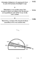
- FIG. 2 shows an exemplary schematic diagram of a plurality of X-rays in a same plane and a cross section of a measured object.
- X-ray L1 emitted from an accelerator target A intersects with the measured object, resulting in intersection points X11 and X12, where X11 is a proximal intersection point and X12 is a distal intersection point.
- the distance between the intersections X11 and X12 is the thickness of the measured object in the direction of X-ray L1.
- the distance between the intersections X21 and X22 is the thickness of the measured object in the direction of X-ray L2.
- the measured object is placed in a container.
- one of the intersection points between the X-ray and the container of the measured object that is closest to the accelerator target can be approximated as the proximal intersection point.
- step S106 a volume of the measured object is determined according to the cross section area.
- the embodiment of the present disclosure can perform a volume measurement with higher accuracy.
- the cross section area of the measured object can be calculated using the principle of calculus.
- An embodiment of a method of calculating the cross section area of a measured object according to the present disclosure will be described below with reference to FIG. 3 .
- FIG. 3 shows a schematic flowchart of a method for calculating a cross section area of the measured object according to some embodiments of the present disclosure. As shown in FIG. 3 , the method of calculating an area of a cross section in this embodiment includes steps S302 to S304.
- step S302 areas of sub-regions divided by the X-rays in the cross section of the measured object are calculated according to the thicknesses corresponding to each of the X-rays in the cross section of the measured object.
- each sub-region may be approximated by a regular shape such as a quadrangle or a sector ring to facilitate calculation. In the calculation, it is also possible to determine more shape data of the sub-region in conjunction with an angle between two adjacent rays.
- step S304 the cross section area of the measured object is determined according to the areas of all sub-regions of the cross section.
- the angle between the adjacent X-rays can be obtained from a related parameter of the accelerator target. In combination with a distance from the accelerator target to the measured object, more size information of the cross section can be obtained. An embodiment of the method of determining a cross section area of the present disclosure will be described below with reference to FIG. 4 .
- FIG. 4 shows a schematic flowchart of a method for determining a cross section area according to other embodiments of the present disclosure. As shown in FIG. 4 , the method of determining a cross section area in this embodiment includes steps S402 to S408.
- step S402 thicknesses of a measured object in each of directions of multiple X-rays emitted from an accelerator target is determined according to measurement results of the X-rays.
- step S404 a proximal distance between the accelerator target and a proximal intersection point on each of the X-rays emitted from the accelerator target is determined, wherein the proximal intersection point is one of the intersection points of the X-ray and the measured object that is closest to the accelerator target.
- X11 in FIG. 2 is the proximal intersection point corresponding to ray L1
- X21 is the proximal intersection point corresponding to ray L2.
- the lengths of AX11 and AX21 can be further calculated based on the obtained thicknesses, or the distance between X11 and X21 can be further calculated based on the angle ⁇ of L1 and L2. Therefore, the area of a cross section can be easily calculated, thus the cross section area can be easily calculated.
- step S406 the cross section area of the measured object is determined according to the thicknesses and the proximal distance corresponding to each of the X-rays in the cross section of the measured object.
- step S408 a volume of the measured object is determined according to the cross section area.
- the cross section area of the measured object can be calculated in conjunction with the distances between the accelerator target and the proximal intersection points, so that the accuracy of the calculation can be further improved.
- a distance between the accelerator target and a proximal intersection point can be obtained based on a scan result of a laser scanner. An embodiment of the method of determining a proximal distance of the present disclosure will be described below with reference to FIG. 5 .
- FIG. 5 shows a schematic flowchart of a method for determining a proximal distance according to some embodiments of the present disclosure. As shown in FIG. 5 , the method of determining a proximal distance in this embodiment includes steps S502 to S506.
- step S502 first relative position information between a laser scanner and each of one or more points on a measurement surface of the measured object according to a measurement result of the laser scanner is acquired.
- the first relative position may include distance information and direction information, for example. Therefore, the laser scanner can obtain profile information of the measurement surface of the measured object.
- the measurement surface refers to a first surface of the measured object that laser rays emitted by the laser scanner and radiation rays emitted by the accelerator target contact. For example, if the measured object is placed on a truck and the laser scanner and the accelerator target are located on the right side of the vehicle, the right side of the measured object is the measurement surface.
- step 504 second relative position information between the laser scanner and the accelerator target is acquired.
- step S506 a proximal distance between the accelerator target and a proximal intersection point on each of the X-rays is determined according to the first relative position information and the second relative position information.
- FIG. 6 shows a schematic measurement diagram of a laser scanner and an accelerator target according to some embodiments of the present disclosure.
- the laser scanner B generates laser rays scanning a measurement surface of the measured object to produce profile data of the measurement surface; the accelerator target A emits X-rays that penetrate the measured object.
- the relative position information may be represented by coordinates.
- two coordinate systems such as polar coordinate systems, can be established with A and B as the origins of the coordinates, respectively. Since the relative position between A and B is known, a mapping relationship between the two coordinate systems can be obtained.
- the coordinates of each point on the measurement surface in the coordinate system with A as the origin can be obtained according to the measurement results of rays emitted by the laser scanner B at multiple angles.
- the coordinates of each point on the measurement surface in the coordinate system with B as the origin can be obtained according to the mapping relationship between the coordinate systems. Therefore, a distance between the accelerator target A and a point on the measurement surface can be obtained, and then a proximal distance between the accelerator target and the proximal intersection point on each X-ray can be further obtained.
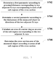
- the inventors have realized that because the X-rays are radiated with the accelerator target as the center, two adjacent X-rays can divide a cross section of the measured object into an approximate sector ring shape. Therefore, an approximate area of a sub-region of the cross section can be obtained by calculating the area of the sector ring. An embodiment of a method of calculating a cross section area of the present disclosure will be described below with reference to FIG. 7 .
- FIG. 7 shows a schematic flowchart of a method for calculating a cross section area according to still other embodiments of the present disclosure. As shown in FIG. 7 , the method of calculating a cross section area in this embodiment includes steps S702 to S708.
- a first parameter is determined according to proximal distances corresponding to two adjacent X-rays corresponding to each of all sub-regions of the cross section of the measured object. For example, any one of an average value, a maximum value, or a minimum value of the two proximal distances may be used as the first parameter.
- a second parameter is determined according to the thicknesses of the measured object in directions of the two adjacent X-rays. For example, any one of an average value, a maximum value, or a minimum value of the two thickness values may be used as the second parameter.
- an area of a sector ring is calculated as an area of the sub-region corresponding to the two adjacent X-rays, with the accelerator target as a center of a circle where the sector ring locates, an angle between the two adjacent X-rays as a central angle of the circle, the first parameter as an inner diameter of the sector ring, and the second parameter as a difference between an outer diameter and the inner diameter of the sector ring.
- step S708 the cross section area of the measured object is determined according to areas of all sub-regions of the cross section.
- FIG. 2 The schematic diagram of calculating the area of a sub-region according to some embodiments of the present disclosure will be described below with reference to FIG. 2 .
- a sub-region divided by the two adjacent X-rays L1 and L2 is represented with a diagonal background.
- the angle between X-rays L1 and L2 is ⁇ .
- the intersection points between X-ray L1 and the measured object are X11 and X12, and the intersection points between X-ray L2 and the measured object are X21 and X22.
- the area of this sub-region can be regarded as a difference between the area of the approximate sector X12AX22 and the area of the approximate sector X11AX21.
- r is the inner diameter of the sector ring, that is, the first parameter
- d is the difference between the outer diameter and the inner diameter, that is, the second parameter.
- an approximate area can be calculated by treating each sub-region as a sector ring. Since the shape of the sector ring is very close to the actual shape of the sub-region, the calculated area of the sub-region is more accurate, thereby improving the accuracy of the volume measurement.
- the shape of the measured object may be very asymmetric, or it may has a skewed distribution.
- the volume may be determined based on multiple measurement results obtained with accelerator targets located in multiple orientations of the measured object. An embodiment of the volume measurement method of the present disclosure will be described below with reference to FIGS. 8A and 8B .
- FIG. 8A shows a schematic flowchart of a volume measurement method according to other embodiments of the present disclosure.
- the accelerator target comprises a first accelerator target and a second accelerator target
- the cross section area of the measured object comprises a first area of the cross section and a second area of the cross section.
- the volume measurement method of this embodiment includes steps S802 to S810.
- step S802 thicknesses of the measured object in each of directions of multiple first X-rays emitted from the first accelerator target located in a first orientation of the measured object is determined according to measurement results of the first X-rays.
- a first area of the cross section is determined according to the thicknesses corresponding to the first X-rays in the cross section.
- step S806 thicknesses of the measured object in each of directions of multiple second X-rays emitted from the second accelerator target located in a second orientation of the measured object is determined according to measurement results of the second X-rays.
- the first orientation and the second orientation are a pair of opposite orientations centered on the measured object.
- step S808 a second area of the cross section is determined according to the thicknesses corresponding to the second X-rays in the cross section.
- the first area and the second area are different calculation results of the same cross section.
- step S810 the volume of the measured object is determined according to a maximum value of the first area and the second area of the cross section.
- FIG. 8B shows a schematic diagram of a measurement scenario according to some embodiments of the present disclosure.
- the measured object located in the square container is inclined toward the left inner wall of the container, and there is a large gap with the right inner wall of the container.
- the volume is calculated in conjunction with the measurement data of a laser scanner, since only a distance from the accelerator target to a container wall can be measured based on a measurement result of the laser scanner, in the case of ignoring the thickness of the container wall, the area determined based on the measurement result of the accelerator target located at the position A1 on the left side of the measured object is more accurate.
- the area determined based on the measurement result of the accelerator target located at the position A2 on the right side of the measured object may be smaller.
- the X-rays emitted by the accelerator target at the position A1 in FIG. 8B are indicated by dashed lines
- the rays emitted by the accelerator target at the position A2 are indicated by the solid lines.
- multiple accelerator targets can be provided to perform measurements simultaneously, or a movable accelerator target can be provided to perform measurements at different times and at different positions.
- the accuracy of volume measurement can be further improved.
- a volume can be determined according to a length of the measured object in a direction perpendicular to the cross section.
- the directions of the X-rays emitted by the accelerator target are perpendicular to a moving direction of the measured object. Therefore, if the measured object is a moving object, the volume can be determined by a moving speed and a time of passing a preset marker of the measured object. An embodiment of the volume determination method will be described below with reference to FIG. 9 .
- FIG. 9 shows a schematic flowchart of a volume determination method according to some embodiments of the present disclosure. As shown in FIG. 9 , the volume determination method in this embodiment includes steps S902 to S904.
- step S902 a moving speed and a time of passing a preset marker of the measured object are acquired.
- the preset marker may be a measurement device, such as a camera or a laser scanner.
- step S904 the volume of the measured object is determined according to the moving speed, the time, and the cross section area of the measured object.
- the volume of the measured object in motion can be quickly determined.
- the calculation of the volume may be a segmented process. Below, an embodiment of determining a volume in a segmented process will be described with reference to FIG. 10 .
- FIG. 10 shows a schematic flowchart of a volume determination method according to other embodiments of the present disclosure.
- the cross section area of the measured object comprises areas of multiple cross sections in the measured object.
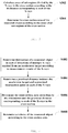
- the volume determination method of this embodiment includes steps S1002 to S1006.
- step S1002 areas of multiple cross sections in the measured object are acquired.
- step S1004 volumes of sub-blocks divided by the cross sections in the measured object are determined according to distances between adjacent cross sections of the multiple cross sections.
- step S1006 a volume of the measured object is determined according to the volumes of the sub-blocks of the measured object.
- areas of multiple cross sections and distances between adjacent sections can be obtained by moving a measuring device such as an accelerator target;
- a measuring device such as an accelerator target
- areas of multiple cross sections can be obtained at different times using a stationary measurement device, and distances between adjacent sections are determined according to the moving speed and passing time of the measured object.
- the volume of an irregular-shaped object can be determined more accurately with the method of the above embodiment.
- a security inspection may be further performed based on the volume measurement result.
- An embodiment of the security inspection method of the present disclosure will be described below with reference to FIG. 11 .
- FIG. 11 shows a schematic flowchart of a security inspection method according to some embodiments of the present disclosure. As shown in FIG. 11 , the security inspection method of this embodiment includes steps S1102 to S1106.
- step S1102 a weight of the measured object is acquired.
- the measured object can be placed on a weighing device.
- the vehicle can be driven in a weighing aisle to obtain a total weight of the vehicle and the measured object.
- a net weight of the vehicle can be obtained. A difference between the total weight and the net weight is the weight of the measured object.
- step S1104 the density of the measured object is calculated according to the weight and the volume of the measured object.
- step S1106 the status of the measured object is determined as abnormal in case that a difference between the calculated density of the measured object and a density of the measured object obtained in advance is greater than a preset range.
- the density of the measured object obtained in advance may be a density corresponding to an item type declared in advance.
- an alarm can be issued for further processing or recording by the security inspector.
- the density of the measured object can be detected quickly without opening the container, which improves the efficiency and convenience of the security inspection.
- the accelerator target may be higher than the lowest plane of the measured object.
- the accelerator target can be automatically raised to ensure that the accelerator target is not lower than the lowest plane of the measured object. This tries to make the X-rays emitted by the accelerator target directly pass through the measured object, and reduce the amount of X-rays that penetrate unrelated objects such as the tires and vehicle chassis as much as possible. Therefore, the accuracy of volume measurement can be further improved.
- FIG. 12 shows a schematic structural diagram of a volume measurement device according to some embodiments of the present disclosure.
- the volume measurement device 1200 of this embodiment includes a thickness determination module 1201 configured to determine thicknesses of a measured object in each of directions of multiple X-rays emitted from an accelerator target according to measurement results of the X-rays; a cross section area determination module 1202 configured to determine a cross section area of the measured object according to the thicknesses corresponding to each of the X-rays in the cross section of the measured object; a volume determination module 1203 configured to determine a volume of the measured object according to the cross section area.
- a thickness determination module 1201 configured to determine thicknesses of a measured object in each of directions of multiple X-rays emitted from an accelerator target according to measurement results of the X-rays
- a cross section area determination module 1202 configured to determine a cross section area of the measured object according to the thicknesses corresponding to each of the X-rays in the cross section of the measured object
- the cross section area determination module 1202 is further configured to calculate areas of sub-regions divided by the X-rays in the cross section of the measured object according to the thicknesses corresponding to each of the X-rays in the cross section of the measured object; and to determine the cross section area of the measured object according to the areas of all sub-regions of the cross section.
- the volume measurement device 1200 further includes: a proximal distance determination module 1204 configured to determine a proximal distance between the accelerator target and a proximal intersection point on each of the X-rays emitted from the accelerator target, wherein the proximal intersection point is one of the intersection points of the X-ray and the measured object that is closest to the accelerator target; the cross section area determination module 1202 is further configured to determine the cross section area of the measured object according to the thicknesses and the proximal distance corresponding to each of the X-rays in the cross section of the measured object.
- the proximal distance determination module 1204 is further configured to acquire first relative position information between a laser scanner and each of one or more points on a measurement surface of the measured object according to a measurement result of the laser scanner; to acquire second relative position information between the laser scanner and the accelerator target; and to determine a proximal distance between the accelerator target and a proximal intersection point on each of the X-rays according to the first relative position information and the second relative position information.
- the cross sectional area determination module 1202 is further configured to determine a first parameter according to proximal distances corresponding to two adjacent X-rays corresponding to each of all sub-regions of the cross section of the measured object; to determine a second parameter according to the thicknesses of the measured object in directions of the two adjacent X-rays; to calculate an area of a sector ring as an area of the sub-region corresponding to the two adjacent X-rays, with the accelerator target as a center of a circle where the sector ring locates, an angle between the two adjacent X-rays as a central angle of the circle, the first parameter as an inner diameter of the sector ring, and the second parameter as a difference between an outer diameter and the inner diameter of the sector ring; and to determine the cross section area of the measured object according to areas of all sub-regions of the cross section.
- the accelerator target comprises a first accelerator target and a second accelerator target
- the cross section area of the measured object comprises a first area of the cross section and a second area of the cross section;
- the first accelerator target is located in a first orientation of the measured object and emits multiple first X-rays, and the first area is determined according to measurement results of the first X-rays in the cross section;
- the second accelerator target is located in a second orientation of the measured object and emits multiple second X-rays, and the second area is determined according to measurement results of the second X-rays in the cross section;
- the volume determination module 1203 is further configured to determine the volume of the measured object according to a maximum value of the first cross section area and the second cross section area.
- the directions of the X-rays emitted by the accelerator target are perpendicular to a moving direction of the measured object.
- the volume determination module 1203 is further configured to acquire a moving speed and a time of passing a preset marker of the measured object; and to determine the volume of the measured object according to the moving speed, the time, and the cross section area of the measured object.
- the cross section area of the measured object comprises areas of multiple cross sections in the measured object; the volume determination module 1203 is further configured to determine volumes of sub-blocks divided by the multiple cross sections in the measured object according to distances between adjacent cross sections of the multiple cross sections; and to determine a volume of the measured object according to the volumes of the sub-blocks of the measured object.
- the volume measurement device 1200 further includes: an abnormality detection module 1205 configured to acquire a weight of the measured object; calculate the density of the measured object according to the weight and the volume of the measured object; and to determine that the status of the measured object is abnormal in case that a difference between the calculated density of the measured object and a density of the measured object obtained in advance is greater than a preset range.
- an abnormality detection module 1205 configured to acquire a weight of the measured object; calculate the density of the measured object according to the weight and the volume of the measured object; and to determine that the status of the measured object is abnormal in case that a difference between the calculated density of the measured object and a density of the measured object obtained in advance is greater than a preset range.
- the measured object is located on a vehicle, and the accelerator target is higher than the lowest plane of the measured object.
- FIG. 13 shows a schematic structural diagram of a volume measurement system according to some embodiments of the present disclosure.
- the volume measurement system 130 of this embodiment includes a volume measurement device 131 and an accelerator target 132.
- the accelerator target 132 is configured to emit a plurality of X-rays toward the measured object to obtain measurement results.
- the volume measurement system 130 further includes a laser scanner 133 configured to scan a measurement surface of the measured object.
- the volume measurement system 130 further includes a speed measuring device 134 configured to detect a moving speed of the measured object; and a timing device 135 configured to detect a time of passing a preset marker of the measured object.
- the volume measurement system 130 further includes a weighing device 136 configured to measure a weight of the measured object.
- FIG. 14 is a schematic structural diagram of a volume measurement device according to other embodiments of the present disclosure.
- the volume measurement device 140 of this embodiment includes a memory 1410 and a processor 1420 coupled to the memory 1410, the processor 1420 configured to, based on instructions stored in the memory 1410, carry out the volume measurement method according to any one of the foregoing embodiments.
- the memory 1410 may include, for example, system memory, a fixed non-volatile storage medium, or the like.
- the system memory stores, for example, an operating system, application programs, a boot loader (Boot Loader), and other programs.
- FIG. 15 is a schematic structural diagram of a volume measurement device according to further embodiments of the present disclosure.
- the volume measurement device 150 in this embodiment includes a memory 1510 and a processor 1520, and may further include an input-output interface 1530, a network interface 1540, a storage interface 1550, and the like. These interfaces 1530, 1540, 1550 and the memory 1510 and the processor 1520 may be connected through a bus 1560, for example.
- the input-output interface 1530 provides a connection interface for input-output devices such as a display, a mouse, a keyboard, and a touch screen.
- the network interface 1540 provides a connection interface for various networked devices.
- the storage interface 1550 provides a connection interface for external storage devices such as an SD card and a USB flash disk.
- An embodiment of the present disclosure also provides a computer-readable storage medium on which a computer program is stored, which is characterized in that when the program is executed by a processor, any one of the foregoing volume measurement methods is implemented.
- embodiments of this disclosure may be provided as a method, a system, or a computer program product. Therefore, embodiments of this disclosure can take the form of an entirely hardware embodiment, an entirely software embodiment or an embodiment containing both hardware and software elements. Moreover, the present disclosure may take the form of a computer program product embodied on one or more computer-usable non-transitory storage media (including but not limited to disk storage, CD-ROM, optical memory, etc.) having computer-usable program code embodied therein.
- computer-usable non-transitory storage media including but not limited to disk storage, CD-ROM, optical memory, etc.
- the present disclosure has been described with reference to flow charts and/or block diagrams of methods, apparatuses (systems) and computer program products according to embodiments of the present disclosure. It should be understood that each process and/or block in the flowcharts and/or block diagrams, and combinations of the processes and/or blocks in the flowcharts and/or block diagrams may be implemented by computer program instructions.
- the computer program instructions may be provided to a processor of a general purpose computer, a special purpose computer, an embedded processor, or other programmable data processing device to generate a machine such that the instructions executed by a processor of a computer or other programmable data processing device to generate means implementing the functions specified in one or more flows of the flowcharts and/or one or more blocks of the block diagrams.
- the computer program instructions may also be stored in a computer readable memory device capable of directing a computer or other programmable data processing device to operate in a specific manner such that the instructions stored in the computer readable memory device produce an article of manufacture including instruction means implementing the functions specified in one or more flows of the flowcharts and/or one or more blocks of the block diagrams.
- These computer program instructions can also be loaded onto a computer or other programmable device to perform a series of operation steps on the computer or other programmable device to generate a computer-implemented process such that the instructions executed on the computer or other programmable device provide steps implementing the functions specified in one or more flows of the flowcharts and/or one or more blocks of the block diagrams.
Landscapes
- Physics & Mathematics (AREA)
- Electromagnetism (AREA)
- General Physics & Mathematics (AREA)
- Analysing Materials By The Use Of Radiation (AREA)
- Length-Measuring Devices Using Wave Or Particle Radiation (AREA)
- Apparatus For Radiation Diagnosis (AREA)
Abstract
Description
- The present disclosure relates to the field of radiation, and in particular, to a volume measurement method, a device, a system, and a computer-readable storage medium.
- The related arts provides a channel-type volume measurement system, which generally uses a regional laser sensor as a measurement tool to obtain shape data of a measured object. A volume of the measured object can be obtained by using a specific algorithm. For example, a system that simply measures the extreme values of the length, width, and height of an object can be used in the fields of height limit, width limit inspection, and ro-ro ship storage bin allocation in the transportation industry. Another volume measurement system, in addition to obtaining the extreme values of the length, width, and height of the measured object, can accurately measure a side profile of the object, and then calculate an object volume based on a real-time speed of the vehicle. This system is restricted to the image recognition algorithm that can only rely on the regional laser to roughly obtain the height of the vehicle chassis, which is then removed in the volume calculation to achieve the purpose of "chassis peeling".
- The inventors have realized that the systems provided by the related arts do not have the ability to penetrate substances or the ability to identify substances, so they cannot distinguish between cargoes and a vehicle chassis. When the cargoes are placed in a container such as a hopper or a container, the system can only obtain the volume of the container, not the actual volume of the object. Moreover, related technologies can only perform a calculation based on the extreme values of the length, width, and height of an object. For irregular objects, its size cannot be measured accurately. Therefore, the calculation accuracy of the related arts is low.
- A technical problem to be solved by the embodiments of the present disclosure is: how to improve the accuracy of volume measurement.
- According to a first aspect of some embodiments of the present disclosure, a volume measurement method is provided, comprising: determining thicknesses of a measured object in each of directions of multiple X-rays emitted from an accelerator target according to measurement results of the X-rays; determining a cross section area of the measured object according to the thicknesses corresponding to each of the X-rays in the cross section of the measured object; and determining a volume of the measured object according to the cross section area.
- In some embodiments, the determining a cross section area of the measured object according to the thicknesses corresponding to each of the X-rays in the cross section of the measured object comprises: calculating areas of sub-regions divided by the X-rays in the cross section of the measured object according to the thicknesses corresponding to each of the X-rays in the cross section of the measured object; and determining the cross section area of the measured object according to the areas of all sub-regions of the cross section.
- In some embodiments, the volume measurement method further comprises: determining a proximal distance between the accelerator target and a proximal intersection point on each of the X-rays emitted from the accelerator target, wherein the proximal intersection point is one of the intersection points of the X-ray and the measured object that is closest to the accelerator target; wherein the determining a cross section area of the measured object according to the thicknesses corresponding to each of the X-rays in the cross section of the measured object comprises: determining the cross section area of the measured object according to the thicknesses and the proximal distance corresponding to each of the X-rays in the cross section of the measured object.
- In some embodiments, the determining the cross section area of the measured object according to the thicknesses and the proximal distance corresponding to each of the X-rays in the cross section of the measured object comprises: determining a first parameter according to proximal distances corresponding to two adjacent X-rays corresponding to each of all sub-regions of the cross section of the measured object; determining a second parameter according to the thicknesses of the measured object in directions of the two adjacent X-rays; calculating an area of a sector ring as an area of the sub-region corresponding to the two adjacent X-rays, with the accelerator target as a center of a circle where the sector ring locates, an angle between the two adjacent X-rays as a central angle of the circle, the first parameter as an inner diameter of the sector ring, and the second parameter as a difference between an outer diameter and the inner diameter of the sector ring; and determining the cross section area of the measured object according to areas of all sub-regions of the cross section.
- In some embodiments, the determining a proximal distance between the accelerator target and a proximal intersection point on each of the X-rays emitted from the accelerator target comprises: acquiring first relative position information between a laser scanner and each of one or more points on a measurement surface of the measured object according to a measurement result of the laser scanner; acquiring second relative position information between the laser scanner and the accelerator target; and determining a proximal distance between the accelerator target and a proximal intersection point on each of the X-rays according to the first relative position information and the second relative position information.
- In some embodiments, the accelerator target comprises a first accelerator target and a second accelerator target, and the cross section area of the measured object comprises a first area of the cross section and a second area of the cross section; the first accelerator target is located in a first orientation of the measured object and emits multiple first X-rays, and the first area is determined according to measurement results of the first X-rays in the cross section; the second accelerator target is located in a second orientation of the measured object and emits multiple second X-rays, and the second area is determined according to measurement results of the second X-rays in the cross section; and the determining a volume of the measured object according to the cross section area comprises: determining the volume of the measured object according to a maximum value of the first cross section area and the second cross section area.
- In some embodiments, the directions of the X-rays emitted by the accelerator target are perpendicular to a moving direction of the measured object.
- In some embodiments, the determining a volume of the measured object according to the cross section area comprises: acquiring a moving speed and a time of passing a preset marker of the measured object; and determining the volume of the measured object according to the moving speed, the time, and the cross section area of the measured object.
- In some embodiments, the cross section area of the measured object comprises areas of multiple cross sections in the measured object; and the determining a volume of the measured object according to the cross section area comprises: determining volumes of sub-blocks divided by the multiple cross sections in the measured object according to distances between adjacent cross sections of the multiple cross sections; and determining a volume of the measured object according to the volumes of the sub-blocks of the measured object.
- In some embodiments, the volume measurement method further comprises: acquiring a weight of the measured object; calculating the density of the measured object according to the weight and the volume of the measured object; and determining that the status of the measured object is abnormal in case that a difference between the calculated density of the measured object and a density of the measured object obtained in advance is greater than a preset range.
- In some embodiments, the measured object is located on a vehicle, and the accelerator target is higher than the lowest plane of the measured object.
- According to a second aspect of some embodiments of the present disclosure, a volume measurement device is provided, comprising: a thickness determination module configured to determine thicknesses of a measured object in each of directions of multiple X-rays emitted from an accelerator target according to measurement results of the X-rays; a cross section area determination module configured to determine a cross section area of the measured object according to the thicknesses corresponding to each of the X-rays in the cross section of the measured object; a volume determination module configured to determine a volume of the measured object according to the cross section area.
- According to a third aspect of some embodiments of the present disclosure, a volume measurement system is provided, comprising: the volume measurement device; and an accelerator target configured to emit multiple X-rays toward the measured object to obtain measurement results.
- According to a fourth aspect of some embodiments of the present disclosure, a volume measurement device is provided, comprising: a memory; a processor coupled to the memory, the processor configured to, based on instructions stored in the memory, carry out any one of the foregoing volume measurement methods.
- According to a fifth aspect of some embodiments of the present disclosure, a computer-readable storage medium is provided on which a computer program is stored, which executed by a processor, implement any one of the foregoing volume measurement methods.
- Some embodiments of the present disclosure have the following advantages or beneficial effects: by applying X-ray scanning to volume measurement, information about the type of substance and size information at multiple positions and angles of the measured object can be obtained from the X-ray measurement results, so that the volume of the measured object can be measured more accurately.
- Other features and advantages of the present disclosure will become apparent from the following detailed description of exemplary embodiments of the present disclosure with reference to the accompanying drawings.
- In order to more clearly explain the embodiments of the present disclosure or the technical solutions in the prior art, a brief introduction will be given below for the drawings required to be used in the description of the embodiments or the prior art. It is obvious that, the drawings illustrated as follows are merely some of the embodiments of the present disclosure. For a person skilled in the art, he or she may also acquire other drawings according to such drawings on the premise that no inventive effort is involved.
-
FIG. 1 shows a schematic flowchart of a volume measurement method according to some embodiments of the present disclosure; -
FIG. 2 shows an exemplary schematic diagram of a plurality of X-rays in a same plane and a cross section of a measured object in the same plane; -
FIG. 3 shows a schematic flowchart of a method for calculating a cross section area according to some embodiments of the present disclosure; -
FIG. 4 shows a schematic flowchart of a method for determining a cross section area according to other embodiments of the present disclosure; -
FIG. 5 shows a schematic flowchart of a method for determining a proximal distance according to some embodiments of the present disclosure; -
FIG. 6 shows a schematic measurement diagram of a laser scanner and an accelerator target according to some embodiments of the present disclosure; -
FIG. 7 shows a schematic flowchart of a method for calculating a cross section area according to still other embodiments of the present disclosure; -
FIG. 8A shows a schematic flowchart of a volume measurement method according to other embodiments of the present disclosure; -
FIG. 8B shows a schematic diagram of a measurement scenario according to some embodiments of the present disclosure; -
FIG. 9 shows a schematic flowchart of a volume determination method according to some embodiments of the present disclosure; -
FIG. 10 shows a schematic flowchart of a volume determination method according to other embodiments of the present disclosure; -
FIG. 11 shows a schematic flowchart of a security inspection method according to some embodiments of the present disclosure; -
FIG. 12 shows a schematic structural diagram of a volume measurement device according to some embodiments of the present disclosure; -
FIG. 13 shows a schematic structural diagram of a volume measurement system according to some embodiments of the present disclosure; -
FIG. 14 shows a schematic structural diagram of a volume measurement device according to other embodiments of the present disclosure; -
FIG. 15 shows a schematic structural diagram of a volume measurement device according to further embodiments of the present disclosure. - A clear and complete description will be given below for the technical solution of some embodiments of this disclosure with reference to the figures. Obviously, merely some embodiments of this disclosure, rather than all embodiments thereof, is given herein. The following description of at least one exemplary embodiment is in fact merely illustrative and is in no way intended as a limitation to the disclosure, its application or use. All other embodiments obtained by those of ordinary skill in the art based on the embodiments of the present disclosure without creative efforts shall fall within the protection scope of the present disclosure.
- Unless otherwise specified, the relative arrangement, numerical expressions and numerical values of the components and steps set forth in these examples do not limit the scope of the disclosure.
- At the same time, it should be understood that, for ease of description, the dimensions of the various parts shown in the drawings are not drawn to actual proportions.
- Techniques, methods, and apparatus known to those of ordinary skill in the relevant art may not be discussed in detail, but where appropriate, these techniques, methods, and apparatuses should be considered as part of the specification.
- Of all the examples shown and discussed herein, any specific value should be construed as merely illustrative and not as a limitation. Thus, other examples of exemplary embodiments may have different values.
- It should be noticed that similar reference numerals and letters are denoted by the like in the accompanying drawings, and therefore, once an article is defined in a drawing, there is no need for further discussion in the accompanying drawings.
-
FIG. 1 shows a schematic flowchart of a volume measurement method according to some embodiments of the present disclosure. As shown inFIG. 1 , the volume measurement method of this embodiment includes steps S102 to S106. - In step S102, thicknesses of a measured object in each of directions of multiple X-rays emitted from an accelerator target is determined according to measurement results of the X-rays.
- Density information of an object through which X-rays pass can be obtained to discriminate substances of different materials. In addition, thickness information of each substance can be obtained. Therefore, even if the measured object is in, for example, a container, the thickness of the measured object can be determined from the measurement result.
- In some embodiments, an accelerator target can emit a set of rays in the same plane at the same time, and the intersection of the plane and the measured object is a cross section of the measured object. This set of rays is located in the same cross section of the measured object.
- In some embodiments, the accelerator target may be fixed or movable. For example, during measurement, the accelerator target may be stationary and the measured object may be movable, or the measured object may be stationary and the accelerator target may be movable. Therefore, a measurement can be performed through emitting radiation rays at different times by the accelerator target, and thicknesses corresponding to the X-rays on multiple cross sections of the measured object can be obtained.
- In step S104, a cross section area of the measured object is determined according to the thicknesses corresponding to each of the X-rays in the cross section of the measured object.
- In this disclosure, the cross section area of the measured object comprises areas of one or more cross sections.
-
FIG. 2 shows an exemplary schematic diagram of a plurality of X-rays in a same plane and a cross section of a measured object. As shown inFIG. 2 , X-ray L1 emitted from an accelerator target A intersects with the measured object, resulting in intersection points X11 and X12, where X11 is a proximal intersection point and X12 is a distal intersection point. The distance between the intersections X11 and X12 is the thickness of the measured object in the direction of X-ray L1. Similarly, the distance between the intersections X21 and X22 is the thickness of the measured object in the direction of X-ray L2. - In some situations, the measured object is placed in a container. In this case, one of the intersection points between the X-ray and the container of the measured object that is closest to the accelerator target can be approximated as the proximal intersection point.
- In step S106, a volume of the measured object is determined according to the cross section area.
- By applying X-ray scanning to volume measurement, information about the type of substance and size information at multiple positions and angles of the measured object can be obtained from the X-ray measurement results, so that the volume of the measured object can be measured more accurately. The above embodiments can be applied to objects with regular and irregular shapes. Furthermore, even if the measured object is located in a container, the volume of the measured object can be obtained without opening the container. Therefore, the range of application of volume measurement is extended, and the measurement efficiency is improved. No matter the object is logs, steel bars, stones, or the like directly loaded on a flatbed vehicle, or coal, gravel, or the like placed in a container, the embodiment of the present disclosure can perform a volume measurement with higher accuracy.
- The inventors have realized that in some embodiments, the cross section area of the measured object can be calculated using the principle of calculus. An embodiment of a method of calculating the cross section area of a measured object according to the present disclosure will be described below with reference to
FIG. 3 . -
FIG. 3 shows a schematic flowchart of a method for calculating a cross section area of the measured object according to some embodiments of the present disclosure. As shown inFIG. 3 , the method of calculating an area of a cross section in this embodiment includes steps S302 to S304. - In step S302, areas of sub-regions divided by the X-rays in the cross section of the measured object are calculated according to the thicknesses corresponding to each of the X-rays in the cross section of the measured object.
- In some embodiments, each sub-region may be approximated by a regular shape such as a quadrangle or a sector ring to facilitate calculation. In the calculation, it is also possible to determine more shape data of the sub-region in conjunction with an angle between two adjacent rays.
- In step S304, the cross section area of the measured object is determined according to the areas of all sub-regions of the cross section.
- Since each X-ray can produce corresponding measurement information, a preliminary calculation can be performed on sub-regions divided by the X-rays, and then the areas of the various sub-regions are summarized. Therefore, the calculation difficulty is reduced, and the calculation efficiency is improved. This method is suitable for calculating the area of a cross section of various shapes.
- In some embodiments, the angle between the adjacent X-rays can be obtained from a related parameter of the accelerator target. In combination with a distance from the accelerator target to the measured object, more size information of the cross section can be obtained. An embodiment of the method of determining a cross section area of the present disclosure will be described below with reference to
FIG. 4 . -
FIG. 4 shows a schematic flowchart of a method for determining a cross section area according to other embodiments of the present disclosure. As shown inFIG. 4 , the method of determining a cross section area in this embodiment includes steps S402 to S408. - In step S402, thicknesses of a measured object in each of directions of multiple X-rays emitted from an accelerator target is determined according to measurement results of the X-rays.
- In step S404, a proximal distance between the accelerator target and a proximal intersection point on each of the X-rays emitted from the accelerator target is determined, wherein the proximal intersection point is one of the intersection points of the X-ray and the measured object that is closest to the accelerator target.
- For example, X11 in
FIG. 2 is the proximal intersection point corresponding to ray L1, and X21 is the proximal intersection point corresponding to ray L2. Through determining the lengths of AX11 and AX21, the lengths of AX12 and AX22 can be further calculated based on the obtained thicknesses, or the distance between X11 and X21 can be further calculated based on the angle θ of L1 and L2. Therefore, the area of a cross section can be easily calculated, thus the cross section area can be easily calculated. - In step S406, the cross section area of the measured object is determined according to the thicknesses and the proximal distance corresponding to each of the X-rays in the cross section of the measured object.
- In step S408, a volume of the measured object is determined according to the cross section area.
- Through the method of the above embodiment, the cross section area of the measured object can be calculated in conjunction with the distances between the accelerator target and the proximal intersection points, so that the accuracy of the calculation can be further improved.
- In some embodiments, a distance between the accelerator target and a proximal intersection point can be obtained based on a scan result of a laser scanner. An embodiment of the method of determining a proximal distance of the present disclosure will be described below with reference to
FIG. 5 . -
FIG. 5 shows a schematic flowchart of a method for determining a proximal distance according to some embodiments of the present disclosure. As shown inFIG. 5 , the method of determining a proximal distance in this embodiment includes steps S502 to S506. - In step S502, first relative position information between a laser scanner and each of one or more points on a measurement surface of the measured object according to a measurement result of the laser scanner is acquired. The first relative position may include distance information and direction information, for example. Therefore, the laser scanner can obtain profile information of the measurement surface of the measured object.
- The measurement surface refers to a first surface of the measured object that laser rays emitted by the laser scanner and radiation rays emitted by the accelerator target contact. For example, if the measured object is placed on a truck and the laser scanner and the accelerator target are located on the right side of the vehicle, the right side of the measured object is the measurement surface.
- In
step 504, second relative position information between the laser scanner and the accelerator target is acquired. - In step S506, a proximal distance between the accelerator target and a proximal intersection point on each of the X-rays is determined according to the first relative position information and the second relative position information.
- Therefore, more measurement data can be obtained using the measurement result of the laser scanner, and the accuracy of the volume measurement is improved.
-
FIG. 6 shows a schematic measurement diagram of a laser scanner and an accelerator target according to some embodiments of the present disclosure. As shown inFIG. 6 , the laser scanner B generates laser rays scanning a measurement surface of the measured object to produce profile data of the measurement surface; the accelerator target A emits X-rays that penetrate the measured object. - In some embodiments, the relative position information may be represented by coordinates. For example, two coordinate systems, such as polar coordinate systems, can be established with A and B as the origins of the coordinates, respectively. Since the relative position between A and B is known, a mapping relationship between the two coordinate systems can be obtained. The coordinates of each point on the measurement surface in the coordinate system with A as the origin can be obtained according to the measurement results of rays emitted by the laser scanner B at multiple angles. The coordinates of each point on the measurement surface in the coordinate system with B as the origin can be obtained according to the mapping relationship between the coordinate systems. Therefore, a distance between the accelerator target A and a point on the measurement surface can be obtained, and then a proximal distance between the accelerator target and the proximal intersection point on each X-ray can be further obtained.
- After further analysis, the inventors have realized that because the X-rays are radiated with the accelerator target as the center, two adjacent X-rays can divide a cross section of the measured object into an approximate sector ring shape. Therefore, an approximate area of a sub-region of the cross section can be obtained by calculating the area of the sector ring. An embodiment of a method of calculating a cross section area of the present disclosure will be described below with reference to
FIG. 7 . -
FIG. 7 shows a schematic flowchart of a method for calculating a cross section area according to still other embodiments of the present disclosure. As shown inFIG. 7 , the method of calculating a cross section area in this embodiment includes steps S702 to S708. - In step S702, a first parameter is determined according to proximal distances corresponding to two adjacent X-rays corresponding to each of all sub-regions of the cross section of the measured object. For example, any one of an average value, a maximum value, or a minimum value of the two proximal distances may be used as the first parameter.
- In step S704, a second parameter is determined according to the thicknesses of the measured object in directions of the two adjacent X-rays. For example, any one of an average value, a maximum value, or a minimum value of the two thickness values may be used as the second parameter.
- In step S706, an area of a sector ring is calculated as an area of the sub-region corresponding to the two adjacent X-rays, with the accelerator target as a center of a circle where the sector ring locates, an angle between the two adjacent X-rays as a central angle of the circle, the first parameter as an inner diameter of the sector ring, and the second parameter as a difference between an outer diameter and the inner diameter of the sector ring.
- In step S708, the cross section area of the measured object is determined according to areas of all sub-regions of the cross section.
- The schematic diagram of calculating the area of a sub-region according to some embodiments of the present disclosure will be described below with reference to
FIG. 2 . As shown inFIG. 2 , a sub-region divided by the two adjacent X-rays L1 and L2 is represented with a diagonal background. The angle between X-rays L1 and L2 is θ. The intersection points between X-ray L1 and the measured object are X11 and X12, and the intersection points between X-ray L2 and the measured object are X21 and X22. The area of this sub-region can be regarded as a difference between the area of the approximate sector X12AX22 and the area of the approximate sector X11AX21. In some embodiments, the area Si of the sub-region may be determined by formula (1):
- In formula (1), r is the inner diameter of the sector ring, that is, the first parameter; d is the difference between the outer diameter and the inner diameter, that is, the second parameter.
- With the method of the above embodiment, an approximate area can be calculated by treating each sub-region as a sector ring. Since the shape of the sector ring is very close to the actual shape of the sub-region, the calculated area of the sub-region is more accurate, thereby improving the accuracy of the volume measurement.
- In some cases, if the measured object is located in a container, the shape of the measured object may be very asymmetric, or it may has a skewed distribution. In order to further improve the accuracy of volume measurement, in some embodiments, the volume may be determined based on multiple measurement results obtained with accelerator targets located in multiple orientations of the measured object. An embodiment of the volume measurement method of the present disclosure will be described below with reference to
FIGS. 8A and 8B . -
FIG. 8A shows a schematic flowchart of a volume measurement method according to other embodiments of the present disclosure. In this embodiment, the accelerator target comprises a first accelerator target and a second accelerator target, and the cross section area of the measured object comprises a first area of the cross section and a second area of the cross section. As shown inFIG. 8A , the volume measurement method of this embodiment includes steps S802 to S810. - In step S802, thicknesses of the measured object in each of directions of multiple first X-rays emitted from the first accelerator target located in a first orientation of the measured object is determined according to measurement results of the first X-rays.
- In step S804, a first area of the cross section is determined according to the thicknesses corresponding to the first X-rays in the cross section.
- In step S806, thicknesses of the measured object in each of directions of multiple second X-rays emitted from the second accelerator target located in a second orientation of the measured object is determined according to measurement results of the second X-rays.
- In some embodiments, the first orientation and the second orientation are a pair of opposite orientations centered on the measured object.
- In step S808, a second area of the cross section is determined according to the thicknesses corresponding to the second X-rays in the cross section.
- Therefore, the first area and the second area are different calculation results of the same cross section.
- In step S810, the volume of the measured object is determined according to a maximum value of the first area and the second area of the cross section.
-
FIG. 8B shows a schematic diagram of a measurement scenario according to some embodiments of the present disclosure. As shown inFIG. 8B , the measured object located in the square container is inclined toward the left inner wall of the container, and there is a large gap with the right inner wall of the container. When the volume is calculated in conjunction with the measurement data of a laser scanner, since only a distance from the accelerator target to a container wall can be measured based on a measurement result of the laser scanner, in the case of ignoring the thickness of the container wall, the area determined based on the measurement result of the accelerator target located at the position A1 on the left side of the measured object is more accurate. The area determined based on the measurement result of the accelerator target located at the position A2 on the right side of the measured object may be smaller. To facilitate the distinction, the X-rays emitted by the accelerator target at the position A1 inFIG. 8B are indicated by dashed lines, and the rays emitted by the accelerator target at the position A2 are indicated by the solid lines. - In some embodiments, multiple accelerator targets can be provided to perform measurements simultaneously, or a movable accelerator target can be provided to perform measurements at different times and at different positions.
- Through the method of the above embodiment, the accuracy of volume measurement can be further improved.
- After obtaining the cross section area, a volume can be determined according to a length of the measured object in a direction perpendicular to the cross section. In some embodiments, the directions of the X-rays emitted by the accelerator target are perpendicular to a moving direction of the measured object. Therefore, if the measured object is a moving object, the volume can be determined by a moving speed and a time of passing a preset marker of the measured object. An embodiment of the volume determination method will be described below with reference to
FIG. 9 . -
FIG. 9 shows a schematic flowchart of a volume determination method according to some embodiments of the present disclosure. As shown inFIG. 9 , the volume determination method in this embodiment includes steps S902 to S904. - In step S902, a moving speed and a time of passing a preset marker of the measured object are acquired. The preset marker may be a measurement device, such as a camera or a laser scanner.
- In step S904, the volume of the measured object is determined according to the moving speed, the time, and the cross section area of the measured object.
- Therefore, the volume of the measured object in motion can be quickly determined.
- In some embodiments, the calculation of the volume may be a segmented process. Below, an embodiment of determining a volume in a segmented process will be described with reference to
FIG. 10 . -
FIG. 10 shows a schematic flowchart of a volume determination method according to other embodiments of the present disclosure. In this embodiment, the cross section area of the measured object comprises areas of multiple cross sections in the measured object. As shown inFIG. 10 , the volume determination method of this embodiment includes steps S1002 to S1006. - In step S1002, areas of multiple cross sections in the measured object are acquired.
- In step S1004, volumes of sub-blocks divided by the cross sections in the measured object are determined according to distances between adjacent cross sections of the multiple cross sections.
- In step S1006, a volume of the measured object is determined according to the volumes of the sub-blocks of the measured object.
- For example, if the measured object is stationary, areas of multiple cross sections and distances between adjacent sections can be obtained by moving a measuring device such as an accelerator target; As another example, if the measured object is a moving object, areas of multiple cross sections can be obtained at different times using a stationary measurement device, and distances between adjacent sections are determined according to the moving speed and passing time of the measured object.
- The volume of an irregular-shaped object can be determined more accurately with the method of the above embodiment.
- In some embodiments, a security inspection may be further performed based on the volume measurement result. An embodiment of the security inspection method of the present disclosure will be described below with reference to
FIG. 11 . -
FIG. 11 shows a schematic flowchart of a security inspection method according to some embodiments of the present disclosure. As shown inFIG. 11 , the security inspection method of this embodiment includes steps S1102 to S1106. - In step S1102, a weight of the measured object is acquired.
- For example, the measured object can be placed on a weighing device. When the measured object is located on a vehicle, the vehicle can be driven in a weighing aisle to obtain a total weight of the vehicle and the measured object. Through obtaining a vehicle type corresponding to the vehicle license plate, a net weight of the vehicle can be obtained. A difference between the total weight and the net weight is the weight of the measured object.
- In step S1104, the density of the measured object is calculated according to the weight and the volume of the measured object.
- In step S1106, the status of the measured object is determined as abnormal in case that a difference between the calculated density of the measured object and a density of the measured object obtained in advance is greater than a preset range. The density of the measured object obtained in advance may be a density corresponding to an item type declared in advance.
- If the status of the measured object is abnormal, for example, an alarm can be issued for further processing or recording by the security inspector.
- Therefore, even if the measured object is loaded in the container, the density of the measured object can be detected quickly without opening the container, which improves the efficiency and convenience of the security inspection.
- In some embodiments, if the measured object is located on a vehicle, the accelerator target may be higher than the lowest plane of the measured object. For example, the accelerator target can be automatically raised to ensure that the accelerator target is not lower than the lowest plane of the measured object. This tries to make the X-rays emitted by the accelerator target directly pass through the measured object, and reduce the amount of X-rays that penetrate unrelated objects such as the tires and vehicle chassis as much as possible. Therefore, the accuracy of volume measurement can be further improved.
- An embodiment of a volume measurement device of the present disclosure will be described below with reference to
FIG. 12 . -
FIG. 12 shows a schematic structural diagram of a volume measurement device according to some embodiments of the present disclosure. As shown inFIG. 12 , the volume measurement device 1200 of this embodiment includes athickness determination module 1201 configured to determine thicknesses of a measured object in each of directions of multiple X-rays emitted from an accelerator target according to measurement results of the X-rays; a cross sectionarea determination module 1202 configured to determine a cross section area of the measured object according to the thicknesses corresponding to each of the X-rays in the cross section of the measured object; avolume determination module 1203 configured to determine a volume of the measured object according to the cross section area. - In some embodiments, the cross section
area determination module 1202 is further configured to calculate areas of sub-regions divided by the X-rays in the cross section of the measured object according to the thicknesses corresponding to each of the X-rays in the cross section of the measured object; and to determine the cross section area of the measured object according to the areas of all sub-regions of the cross section. - In some embodiments, the volume measurement device 1200 further includes: a proximal distance determination module 1204 configured to determine a proximal distance between the accelerator target and a proximal intersection point on each of the X-rays emitted from the accelerator target, wherein the proximal intersection point is one of the intersection points of the X-ray and the measured object that is closest to the accelerator target; the cross section
area determination module 1202 is further configured to determine the cross section area of the measured object according to the thicknesses and the proximal distance corresponding to each of the X-rays in the cross section of the measured object. - In some embodiments, the proximal distance determination module 1204 is further configured to acquire first relative position information between a laser scanner and each of one or more points on a measurement surface of the measured object according to a measurement result of the laser scanner; to acquire second relative position information between the laser scanner and the accelerator target; and to determine a proximal distance between the accelerator target and a proximal intersection point on each of the X-rays according to the first relative position information and the second relative position information.
- In some embodiments, the cross sectional
area determination module 1202 is further configured to determine a first parameter according to proximal distances corresponding to two adjacent X-rays corresponding to each of all sub-regions of the cross section of the measured object; to determine a second parameter according to the thicknesses of the measured object in directions of the two adjacent X-rays; to calculate an area of a sector ring as an area of the sub-region corresponding to the two adjacent X-rays, with the accelerator target as a center of a circle where the sector ring locates, an angle between the two adjacent X-rays as a central angle of the circle, the first parameter as an inner diameter of the sector ring, and the second parameter as a difference between an outer diameter and the inner diameter of the sector ring; and to determine the cross section area of the measured object according to areas of all sub-regions of the cross section. - In some embodiments, the accelerator target comprises a first accelerator target and a second accelerator target, and the cross section area of the measured object comprises a first area of the cross section and a second area of the cross section; the first accelerator target is located in a first orientation of the measured object and emits multiple first X-rays, and the first area is determined according to measurement results of the first X-rays in the cross section; the second accelerator target is located in a second orientation of the measured object and emits multiple second X-rays, and the second area is determined according to measurement results of the second X-rays in the cross section; the
volume determination module 1203 is further configured to determine the volume of the measured object according to a maximum value of the first cross section area and the second cross section area. - In some embodiments, the directions of the X-rays emitted by the accelerator target are perpendicular to a moving direction of the measured object.
- In some embodiments, the
volume determination module 1203 is further configured to acquire a moving speed and a time of passing a preset marker of the measured object; and to determine the volume of the measured object according to the moving speed, the time, and the cross section area of the measured object. - In some embodiments, the cross section area of the measured object comprises areas of multiple cross sections in the measured object; the
volume determination module 1203 is further configured to determine volumes of sub-blocks divided by the multiple cross sections in the measured object according to distances between adjacent cross sections of the multiple cross sections; and to determine a volume of the measured object according to the volumes of the sub-blocks of the measured object. - In some embodiments, the volume measurement device 1200 further includes: an
abnormality detection module 1205 configured to acquire a weight of the measured object; calculate the density of the measured object according to the weight and the volume of the measured object; and to determine that the status of the measured object is abnormal in case that a difference between the calculated density of the measured object and a density of the measured object obtained in advance is greater than a preset range. - In some embodiments, the measured object is located on a vehicle, and the accelerator target is higher than the lowest plane of the measured object.
- An embodiment of a volume measurement system of the present disclosure will be described below with reference to
FIG. 13 . -
FIG. 13 shows a schematic structural diagram of a volume measurement system according to some embodiments of the present disclosure. As shown inFIG. 13 , thevolume measurement system 130 of this embodiment includes avolume measurement device 131 and anaccelerator target 132. For the specific implementation of thevolume measurement device 131, reference may be made to thevolume measurement device 120 in the foregoing embodiment, which will not be repeated herein. Theaccelerator target 132 is configured to emit a plurality of X-rays toward the measured object to obtain measurement results. - In some embodiments, the
volume measurement system 130 further includes alaser scanner 133 configured to scan a measurement surface of the measured object. - In some embodiments, the
volume measurement system 130 further includes aspeed measuring device 134 configured to detect a moving speed of the measured object; and atiming device 135 configured to detect a time of passing a preset marker of the measured object. - In some embodiments, the
volume measurement system 130 further includes a weighingdevice 136 configured to measure a weight of the measured object. -
FIG. 14 is a schematic structural diagram of a volume measurement device according to other embodiments of the present disclosure. As shown inFIG. 14 , thevolume measurement device 140 of this embodiment includes amemory 1410 and aprocessor 1420 coupled to thememory 1410, theprocessor 1420 configured to, based on instructions stored in thememory 1410, carry out the volume measurement method according to any one of the foregoing embodiments. - Wherein, the
memory 1410 may include, for example, system memory, a fixed non-volatile storage medium, or the like. The system memory stores, for example, an operating system, application programs, a boot loader (Boot Loader), and other programs. -
FIG. 15 is a schematic structural diagram of a volume measurement device according to further embodiments of the present disclosure. As shown inFIG. 15 , thevolume measurement device 150 in this embodiment includes amemory 1510 and aprocessor 1520, and may further include an input-output interface 1530, anetwork interface 1540, astorage interface 1550, and the like. Theseinterfaces memory 1510 and theprocessor 1520 may be connected through abus 1560, for example. The input-output interface 1530 provides a connection interface for input-output devices such as a display, a mouse, a keyboard, and a touch screen. Thenetwork interface 1540 provides a connection interface for various networked devices. Thestorage interface 1550 provides a connection interface for external storage devices such as an SD card and a USB flash disk. - An embodiment of the present disclosure also provides a computer-readable storage medium on which a computer program is stored, which is characterized in that when the program is executed by a processor, any one of the foregoing volume measurement methods is implemented.
- One skilled in the art should understand that, the embodiments of this disclosure may be provided as a method, a system, or a computer program product. Therefore, embodiments of this disclosure can take the form of an entirely hardware embodiment, an entirely software embodiment or an embodiment containing both hardware and software elements. Moreover, the present disclosure may take the form of a computer program product embodied on one or more computer-usable non-transitory storage media (including but not limited to disk storage, CD-ROM, optical memory, etc.) having computer-usable program code embodied therein.
- The present disclosure has been described with reference to flow charts and/or block diagrams of methods, apparatuses (systems) and computer program products according to embodiments of the present disclosure. It should be understood that each process and/or block in the flowcharts and/or block diagrams, and combinations of the processes and/or blocks in the flowcharts and/or block diagrams may be implemented by computer program instructions. The computer program instructions may be provided to a processor of a general purpose computer, a special purpose computer, an embedded processor, or other programmable data processing device to generate a machine such that the instructions executed by a processor of a computer or other programmable data processing device to generate means implementing the functions specified in one or more flows of the flowcharts and/or one or more blocks of the block diagrams.
- The computer program instructions may also be stored in a computer readable memory device capable of directing a computer or other programmable data processing device to operate in a specific manner such that the instructions stored in the computer readable memory device produce an article of manufacture including instruction means implementing the functions specified in one or more flows of the flowcharts and/or one or more blocks of the block diagrams.
- These computer program instructions can also be loaded onto a computer or other programmable device to perform a series of operation steps on the computer or other programmable device to generate a computer-implemented process such that the instructions executed on the computer or other programmable device provide steps implementing the functions specified in one or more flows of the flowcharts and/or one or more blocks of the block diagrams.
- The above is merely preferred embodiments of this disclosure, and is not limitation to this disclosure. Within spirit and principles of this utility model, any modification, replacement, improvement and etc. shall be contained in the protection scope of this disclosure.
Claims (15)
- A volume measurement method, characterized by comprising:determining thicknesses of a measured object in each of directions of multiple X-rays emitted from an accelerator target according to measurement results of the X-rays;determining a cross section area of the measured object according to the thicknesses corresponding to each of the X-rays in the cross section of the measured object; anddetermining a volume of the measured object according to the cross section area.
- The volume measurement method according to claim 1, characterized in that the determining a cross section area of the measured object according to the thicknesses corresponding to each of the X-rays in the cross section of the measured object comprises:calculating areas of sub-regions divided by the X-rays in the cross section of the measured object according to the thicknesses corresponding to each of the X-rays in the cross section of the measured object; anddetermining the cross section area of the measured object according to the areas of all sub-regions of the cross section.
- The volume measurement method according to claim 1, characterized by further comprising:determining a proximal distance between the accelerator target and a proximal intersection point on each of the X-rays emitted from the accelerator target, wherein the proximal intersection point is one of the intersection points of the X-ray and the measured object that is closest to the accelerator target;wherein the determining a cross section area of the measured object according to the thicknesses corresponding to each of the X-rays in the cross section of the measured object comprises:
determining the cross section area of the measured object according to the thicknesses and the proximal distance corresponding to each of the X-rays in the cross section of the measured object. - The volume measurement method according to claim 3, characterized in that the determining the cross section area of the measured object according to the thicknesses and the proximal distance corresponding to each of the X-rays in the cross section of the measured object comprises:determining a first parameter according to proximal distances corresponding to two adjacent X-rays corresponding to each of all sub-regions of the cross section of the measured object;determining a second parameter according to the thicknesses of the measured object in directions of the two adjacent X-rays;calculating an area of a sector ring as an area of the sub-region corresponding to the two adjacent X-rays, with the accelerator target as a center of a circle where the sector ring locates, an angle between the two adjacent X-rays as a central angle of the circle, the first parameter as an inner diameter of the sector ring, and the second parameter as a difference between an outer diameter and the inner diameter of the sector ring; anddetermining the cross section area of the measured object according to areas of all sub-regions of the cross section.
- The volume measurement method according to claim 3, characterized in that the determining a proximal distance between the accelerator target and a proximal intersection point on each of the X-rays emitted from the accelerator target comprises:acquiring first relative position information between a laser scanner and each of one or more points on a measurement surface of the measured object according to a measurement result of the laser scanner;acquiring second relative position information between the laser scanner and the accelerator target; anddetermining a proximal distance between the accelerator target and a proximal intersection point on each of the X-rays according to the first relative position information and the second relative position information.
- The volume measurement method according to any one of claims 1 to 5, characterized in that:the accelerator target comprises a first accelerator target and a second accelerator target, and the cross section area of the measured object comprises a first area of the cross section and a second area of the cross section;the first accelerator target is located in a first orientation of the measured object and emits multiple first X-rays, and the first area is determined according to measurement results of the first X-rays in the cross section;the second accelerator target is located in a second orientation of the measured object and emits multiple second X-rays, and the second area is determined according to measurement results of the second X-rays in the cross section; andthe determining a volume of the measured object according to the cross section area comprises: determining the volume of the measured object according to a maximum value of the first cross section area and the second cross section area.
- The volume measurement method according to claim 1, characterized in that the directions of the X-rays emitted by the accelerator target are perpendicular to a moving direction of the measured object.
- The volume measurement method according to claim 7, characterized in that the determining a volume of the measured object according to the cross section area comprises:acquiring a moving speed and a time of passing a preset marker of the measured object; anddetermining the volume of the measured object according to the moving speed, the time, and the cross section area of the measured object.
- The volume measurement method according to claim 1, characterized in that the cross section area of the measured object comprises areas of multiple cross sections in the measured object; and
the determining a volume of the measured object according to the cross section area comprises:determining volumes of sub-blocks divided by the multiple cross sections in the measured object according to distances between adjacent cross sections of the multiple cross sections; anddetermining a volume of the measured object according to the volumes of the sub-blocks of the measured object. - The volume measurement method according to claim 1, characterized by further comprising:acquiring a weight of the measured object;calculating the density of the measured object according to the weight and the volume of the measured object; anddetermining that the status of the measured object is abnormal in case that a difference between the calculated density of the measured object and a density of the measured object obtained in advance is greater than a preset range.
- The volume measurement method according to claim 1, characterized in that the measured object is located on a vehicle, and the accelerator target is higher than the lowest plane of the measured object.
- A volume measurement device, characterized by comprising:a thickness determination module configured to determine thicknesses of a measured object in each of directions of multiple X-rays emitted from an accelerator target according to measurement results of the X-rays;a cross section area determination module configured to determine a cross section area of the measured object according to the thicknesses corresponding to each of the X-rays in the cross section of the measured object;a volume determination module configured to determine a volume of the measured object according to the cross section area.
- A volume measurement system, characterized by comprising:a volume measurement device according to claim 12; andan accelerator target configured to emit multiple X-rays toward the measured object to obtain measurement results.
- A volume measurement device, characterized by comprising:a memory; anda processor coupled to the memory, the processor configured to, based on instructions stored in the memory, carry out the volume measurement method according to any one of claims 1 to 11.
- A computer-readable storage medium, characterized by on which a computer program is stored, which when executed by a processor implements the volume measurement method according to any one of claims 1 to 11.
Applications Claiming Priority (1)
| Application Number | Priority Date | Filing Date | Title |
|---|---|---|---|
| CN201910275709.5A CN109990744B (en) | 2019-04-08 | 2019-04-08 | Volume measurement method, apparatus, system and computer readable storage medium |
Publications (3)
| Publication Number | Publication Date |
|---|---|
| EP3722747A2 true EP3722747A2 (en) | 2020-10-14 |
| EP3722747A3 EP3722747A3 (en) | 2020-10-21 |
| EP3722747B1 EP3722747B1 (en) | 2024-07-31 |
Family
ID=67131247
Family Applications (1)
| Application Number | Title | Priority Date | Filing Date |
|---|---|---|---|
| EP20162528.2A Active EP3722747B1 (en) | 2019-04-08 | 2020-03-11 | Volume measurement method, device, system and computer-readable storage medium |
Country Status (2)
| Country | Link |
|---|---|
| EP (1) | EP3722747B1 (en) |
| CN (1) | CN109990744B (en) |
Cited By (3)
| Publication number | Priority date | Publication date | Assignee | Title |
|---|---|---|---|---|
| US20220245837A1 (en) * | 2021-02-04 | 2022-08-04 | Pixart Imaging Inc. | Movement direction determination system and object volume computation system |
| CN116029975A (en) * | 2022-11-02 | 2023-04-28 | 福建自贸试验区厦门片区Manteia数据科技有限公司 | Recommended method and apparatus, processor and electronics for field angles |
| CN116930218A (en) * | 2022-09-01 | 2023-10-24 | 埃尔西斯株式会社 | X-ray shooting position determination method for detecting object defects |
Families Citing this family (1)
| Publication number | Priority date | Publication date | Assignee | Title |
|---|---|---|---|---|
| CN111795661B (en) * | 2020-06-29 | 2022-01-28 | 中国科学院声学研究所 | Method and system for detecting three-dimensional geometric morphology of underwater acoustic material |
Family Cites Families (7)
| Publication number | Priority date | Publication date | Assignee | Title |
|---|---|---|---|---|
| CN85106686B (en) * | 1985-09-05 | 1987-07-22 | 雷恩自动机株式会社 | Method for continuous measurement of continuously conveyed long objects |
| US5739426A (en) * | 1996-01-19 | 1998-04-14 | Storm; Thomas W. | Volume measurement apparatus and method |
| GB2355071A (en) * | 1999-10-08 | 2001-04-11 | Cintex Ltd | Non-contact volume measurement |
| JP4127698B2 (en) * | 2005-04-25 | 2008-07-30 | アンリツ産機システム株式会社 | X-ray inspection equipment |
| CN101802595B (en) * | 2007-09-26 | 2013-09-04 | 株式会社石田 | Check device |
| CN102628682A (en) * | 2012-04-24 | 2012-08-08 | 重庆大学 | Volume measurement method based on industrial CT scanning technology |
| DE102013001808A1 (en) * | 2013-02-04 | 2014-08-07 | Ge Sensing & Inspection Technologies Gmbh | Method for non-destructive testing of the volume of a test object and test device set up to carry out such a method |
-
2019
- 2019-04-08 CN CN201910275709.5A patent/CN109990744B/en active Active
-
2020
- 2020-03-11 EP EP20162528.2A patent/EP3722747B1/en active Active
Cited By (6)
| Publication number | Priority date | Publication date | Assignee | Title |
|---|---|---|---|---|
| US20220245837A1 (en) * | 2021-02-04 | 2022-08-04 | Pixart Imaging Inc. | Movement direction determination system and object volume computation system |
| CN115507911A (en) * | 2021-02-04 | 2022-12-23 | 原相科技股份有限公司 | Moving direction determination system and object volume calculation system |
| US12211219B2 (en) * | 2021-02-04 | 2025-01-28 | Pixart Imaging Inc. | Movement direction determination system and object volume computation system |
| CN116930218A (en) * | 2022-09-01 | 2023-10-24 | 埃尔西斯株式会社 | X-ray shooting position determination method for detecting object defects |
| CN116930218B (en) * | 2022-09-01 | 2024-04-30 | 埃尔西斯株式会社 | X-ray photographing position determining method for detecting object defect |
| CN116029975A (en) * | 2022-11-02 | 2023-04-28 | 福建自贸试验区厦门片区Manteia数据科技有限公司 | Recommended method and apparatus, processor and electronics for field angles |
Also Published As
| Publication number | Publication date |
|---|---|
| CN109990744B (en) | 2020-09-11 |
| EP3722747A3 (en) | 2020-10-21 |
| EP3722747B1 (en) | 2024-07-31 |
| CN109990744A (en) | 2019-07-09 |
Similar Documents
| Publication | Publication Date | Title |
|---|---|---|
| EP3722747B1 (en) | Volume measurement method, device, system and computer-readable storage medium | |
| CN109188448B (en) | Point cloud non-ground point filtering method and device and storage medium | |
| Ray et al. | Computing 3D blind spots of construction equipment: Implementation and evaluation of an automated measurement and visualization method utilizing range point cloud data | |
| EP3176605A1 (en) | Method and device for monitoring state of moving object and system for fast inspecting vehicle | |
| CN115931633B (en) | Detection method, surface density device, detection apparatus, and storage medium | |
| EP0380659A1 (en) | Method of recognizing linear pattern | |
| CN112731440A (en) | High-speed railway slope deformation detection method and device | |
| CN103268409B (en) | A kind of method measuring tunnel-liner rock fracture width | |
| CN105333826A (en) | Quick vehicle inspection method and system | |
| JP2006234494A (en) | Object recognition device | |
| CN105092616A (en) | Method for measuring minor detail feature sizes in industrial CT (computerized tomography) detection | |
| CN117422777A (en) | Security check machine calibration method, related method, device, equipment and storage medium | |
| US8897534B2 (en) | Method and evaluation device for determining the position of a structure located in an object to be examined by means of X-ray computer tomography | |
| CN107589420A (en) | A kind of interior of articles component detection method, apparatus and system | |
| US20240221343A1 (en) | Display processing device, display processing method, and display processing program | |
| JP6686776B2 (en) | Step detection method and step detection apparatus | |
| CN119461113B (en) | Intelligent monitoring and early warning method, system and storage medium for crane | |
| JP4662147B2 (en) | Object recognition device | |
| EP4332731B1 (en) | Human-computer interaction movement track detection method, apparatus, device, and readable storage medium | |
| CN117157553A (en) | Laser radar detection method and device, terminal equipment and storage medium | |
| JP3499654B2 (en) | Radar image signal processing device | |
| JP2006234493A (en) | Object recognition apparatus and method | |
| SE2030214A1 (en) | Method and arrangement for a work machine | |
| CN205484790U (en) | Target height finding distancer on water | |
| CN116128842B (en) | Material Sampling Method and Apparatus Based on Point Cloud Data |
Legal Events
| Date | Code | Title | Description |
|---|---|---|---|
| PUAI | Public reference made under article 153(3) epc to a published international application that has entered the european phase |
Free format text: ORIGINAL CODE: 0009012 |
|
| STAA | Information on the status of an ep patent application or granted ep patent |
Free format text: STATUS: THE APPLICATION HAS BEEN PUBLISHED |
|
| PUAL | Search report despatched |
Free format text: ORIGINAL CODE: 0009013 |
|
| AK | Designated contracting states |
Kind code of ref document: A2 Designated state(s): AL AT BE BG CH CY CZ DE DK EE ES FI FR GB GR HR HU IE IS IT LI LT LU LV MC MK MT NL NO PL PT RO RS SE SI SK SM TR |
|
| AX | Request for extension of the european patent |
Extension state: BA ME |
|
| AK | Designated contracting states |
Kind code of ref document: A3 Designated state(s): AL AT BE BG CH CY CZ DE DK EE ES FI FR GB GR HR HU IE IS IT LI LT LU LV MC MK MT NL NO PL PT RO RS SE SI SK SM TR |
|
| AX | Request for extension of the european patent |
Extension state: BA ME |
|
| RIC1 | Information provided on ipc code assigned before grant |
Ipc: G01B 11/24 20060101ALN20200915BHEP Ipc: G01B 15/00 20060101AFI20200915BHEP Ipc: G01B 15/02 20060101ALN20200915BHEP |
|
| STAA | Information on the status of an ep patent application or granted ep patent |
Free format text: STATUS: REQUEST FOR EXAMINATION WAS MADE |
|
| 17P | Request for examination filed |
Effective date: 20210414 |
|
| RBV | Designated contracting states (corrected) |
Designated state(s): AL AT BE BG CH CY CZ DE DK EE ES FI FR GB GR HR HU IE IS IT LI LT LU LV MC MK MT NL NO PL PT RO RS SE SI SK SM TR |
|
| STAA | Information on the status of an ep patent application or granted ep patent |
Free format text: STATUS: EXAMINATION IS IN PROGRESS |
|
| 17Q | First examination report despatched |
Effective date: 20221109 |
|
| GRAP | Despatch of communication of intention to grant a patent |
Free format text: ORIGINAL CODE: EPIDOSNIGR1 |
|
| STAA | Information on the status of an ep patent application or granted ep patent |
Free format text: STATUS: GRANT OF PATENT IS INTENDED |
|
| RIC1 | Information provided on ipc code assigned before grant |
Ipc: G01B 15/02 20060101ALN20240123BHEP Ipc: G01B 11/24 20060101ALN20240123BHEP Ipc: G01B 15/00 20060101AFI20240123BHEP |
|
| RIC1 | Information provided on ipc code assigned before grant |
Ipc: G01B 15/02 20060101ALN20240206BHEP Ipc: G01B 11/24 20060101ALN20240206BHEP Ipc: G01B 15/00 20060101AFI20240206BHEP |
|
| INTG | Intention to grant announced |
Effective date: 20240223 |
|
| RAP3 | Party data changed (applicant data changed or rights of an application transferred) |
Owner name: TSINGHUA UNIVERSITY Owner name: NUCTECH (BEIJING) COMPANY LIMITED Owner name: NUCTECH COMPANY LIMITED |
|
| GRAS | Grant fee paid |
Free format text: ORIGINAL CODE: EPIDOSNIGR3 |
|
| GRAA | (expected) grant |
Free format text: ORIGINAL CODE: 0009210 |
|
| STAA | Information on the status of an ep patent application or granted ep patent |
Free format text: STATUS: THE PATENT HAS BEEN GRANTED |
|
| AK | Designated contracting states |
Kind code of ref document: B1 Designated state(s): AL AT BE BG CH CY CZ DE DK EE ES FI FR GB GR HR HU IE IS IT LI LT LU LV MC MK MT NL NO PL PT RO RS SE SI SK SM TR |
|
| REG | Reference to a national code |
Ref country code: CH Ref legal event code: EP Ref country code: GB Ref legal event code: FG4D |
|
| REG | Reference to a national code |
Ref country code: DE Ref legal event code: R096 Ref document number: 602020034714 Country of ref document: DE |
|
| REG | Reference to a national code |
Ref country code: IE Ref legal event code: FG4D |
|
| REG | Reference to a national code |
Ref country code: LT Ref legal event code: MG9D |
|
| REG | Reference to a national code |
Ref country code: NL Ref legal event code: MP Effective date: 20240731 |
|
| PG25 | Lapsed in a contracting state [announced via postgrant information from national office to epo] |
Ref country code: PT Free format text: LAPSE BECAUSE OF FAILURE TO SUBMIT A TRANSLATION OF THE DESCRIPTION OR TO PAY THE FEE WITHIN THE PRESCRIBED TIME-LIMIT Effective date: 20241202 |
|
| REG | Reference to a national code |
Ref country code: AT Ref legal event code: MK05 Ref document number: 1708840 Country of ref document: AT Kind code of ref document: T Effective date: 20240731 |
|
| PG25 | Lapsed in a contracting state [announced via postgrant information from national office to epo] |
Ref country code: PT Free format text: LAPSE BECAUSE OF FAILURE TO SUBMIT A TRANSLATION OF THE DESCRIPTION OR TO PAY THE FEE WITHIN THE PRESCRIBED TIME-LIMIT Effective date: 20241202 |
|
| PG25 | Lapsed in a contracting state [announced via postgrant information from national office to epo] |
Ref country code: NO Free format text: LAPSE BECAUSE OF FAILURE TO SUBMIT A TRANSLATION OF THE DESCRIPTION OR TO PAY THE FEE WITHIN THE PRESCRIBED TIME-LIMIT Effective date: 20241031 |
|
| PG25 | Lapsed in a contracting state [announced via postgrant information from national office to epo] |
Ref country code: NL Free format text: LAPSE BECAUSE OF FAILURE TO SUBMIT A TRANSLATION OF THE DESCRIPTION OR TO PAY THE FEE WITHIN THE PRESCRIBED TIME-LIMIT Effective date: 20240731 Ref country code: FI Free format text: LAPSE BECAUSE OF FAILURE TO SUBMIT A TRANSLATION OF THE DESCRIPTION OR TO PAY THE FEE WITHIN THE PRESCRIBED TIME-LIMIT Effective date: 20240731 Ref country code: PL Free format text: LAPSE BECAUSE OF FAILURE TO SUBMIT A TRANSLATION OF THE DESCRIPTION OR TO PAY THE FEE WITHIN THE PRESCRIBED TIME-LIMIT Effective date: 20240731 Ref country code: GR Free format text: LAPSE BECAUSE OF FAILURE TO SUBMIT A TRANSLATION OF THE DESCRIPTION OR TO PAY THE FEE WITHIN THE PRESCRIBED TIME-LIMIT Effective date: 20241101 |
|
| PG25 | Lapsed in a contracting state [announced via postgrant information from national office to epo] |
Ref country code: BG Free format text: LAPSE BECAUSE OF FAILURE TO SUBMIT A TRANSLATION OF THE DESCRIPTION OR TO PAY THE FEE WITHIN THE PRESCRIBED TIME-LIMIT Effective date: 20240731 |
|
| PG25 | Lapsed in a contracting state [announced via postgrant information from national office to epo] |
Ref country code: LV Free format text: LAPSE BECAUSE OF FAILURE TO SUBMIT A TRANSLATION OF THE DESCRIPTION OR TO PAY THE FEE WITHIN THE PRESCRIBED TIME-LIMIT Effective date: 20240731 |
|
| PG25 | Lapsed in a contracting state [announced via postgrant information from national office to epo] |
Ref country code: IS Free format text: LAPSE BECAUSE OF FAILURE TO SUBMIT A TRANSLATION OF THE DESCRIPTION OR TO PAY THE FEE WITHIN THE PRESCRIBED TIME-LIMIT Effective date: 20241130 Ref country code: AT Free format text: LAPSE BECAUSE OF FAILURE TO SUBMIT A TRANSLATION OF THE DESCRIPTION OR TO PAY THE FEE WITHIN THE PRESCRIBED TIME-LIMIT Effective date: 20240731 |
|
| PG25 | Lapsed in a contracting state [announced via postgrant information from national office to epo] |
Ref country code: HR Free format text: LAPSE BECAUSE OF FAILURE TO SUBMIT A TRANSLATION OF THE DESCRIPTION OR TO PAY THE FEE WITHIN THE PRESCRIBED TIME-LIMIT Effective date: 20240731 |
|
| PG25 | Lapsed in a contracting state [announced via postgrant information from national office to epo] |
Ref country code: RS Free format text: LAPSE BECAUSE OF FAILURE TO SUBMIT A TRANSLATION OF THE DESCRIPTION OR TO PAY THE FEE WITHIN THE PRESCRIBED TIME-LIMIT Effective date: 20241031 Ref country code: ES Free format text: LAPSE BECAUSE OF FAILURE TO SUBMIT A TRANSLATION OF THE DESCRIPTION OR TO PAY THE FEE WITHIN THE PRESCRIBED TIME-LIMIT Effective date: 20240731 |
|
| PG25 | Lapsed in a contracting state [announced via postgrant information from national office to epo] |
Ref country code: RS Free format text: LAPSE BECAUSE OF FAILURE TO SUBMIT A TRANSLATION OF THE DESCRIPTION OR TO PAY THE FEE WITHIN THE PRESCRIBED TIME-LIMIT Effective date: 20241031 Ref country code: PL Free format text: LAPSE BECAUSE OF FAILURE TO SUBMIT A TRANSLATION OF THE DESCRIPTION OR TO PAY THE FEE WITHIN THE PRESCRIBED TIME-LIMIT Effective date: 20240731 Ref country code: NO Free format text: LAPSE BECAUSE OF FAILURE TO SUBMIT A TRANSLATION OF THE DESCRIPTION OR TO PAY THE FEE WITHIN THE PRESCRIBED TIME-LIMIT Effective date: 20241031 Ref country code: NL Free format text: LAPSE BECAUSE OF FAILURE TO SUBMIT A TRANSLATION OF THE DESCRIPTION OR TO PAY THE FEE WITHIN THE PRESCRIBED TIME-LIMIT Effective date: 20240731 Ref country code: LV Free format text: LAPSE BECAUSE OF FAILURE TO SUBMIT A TRANSLATION OF THE DESCRIPTION OR TO PAY THE FEE WITHIN THE PRESCRIBED TIME-LIMIT Effective date: 20240731 Ref country code: IS Free format text: LAPSE BECAUSE OF FAILURE TO SUBMIT A TRANSLATION OF THE DESCRIPTION OR TO PAY THE FEE WITHIN THE PRESCRIBED TIME-LIMIT Effective date: 20241130 Ref country code: HR Free format text: LAPSE BECAUSE OF FAILURE TO SUBMIT A TRANSLATION OF THE DESCRIPTION OR TO PAY THE FEE WITHIN THE PRESCRIBED TIME-LIMIT Effective date: 20240731 Ref country code: GR Free format text: LAPSE BECAUSE OF FAILURE TO SUBMIT A TRANSLATION OF THE DESCRIPTION OR TO PAY THE FEE WITHIN THE PRESCRIBED TIME-LIMIT Effective date: 20241101 Ref country code: FI Free format text: LAPSE BECAUSE OF FAILURE TO SUBMIT A TRANSLATION OF THE DESCRIPTION OR TO PAY THE FEE WITHIN THE PRESCRIBED TIME-LIMIT Effective date: 20240731 Ref country code: ES Free format text: LAPSE BECAUSE OF FAILURE TO SUBMIT A TRANSLATION OF THE DESCRIPTION OR TO PAY THE FEE WITHIN THE PRESCRIBED TIME-LIMIT Effective date: 20240731 Ref country code: BG Free format text: LAPSE BECAUSE OF FAILURE TO SUBMIT A TRANSLATION OF THE DESCRIPTION OR TO PAY THE FEE WITHIN THE PRESCRIBED TIME-LIMIT Effective date: 20240731 Ref country code: AT Free format text: LAPSE BECAUSE OF FAILURE TO SUBMIT A TRANSLATION OF THE DESCRIPTION OR TO PAY THE FEE WITHIN THE PRESCRIBED TIME-LIMIT Effective date: 20240731 |
|
| PG25 | Lapsed in a contracting state [announced via postgrant information from national office to epo] |
Ref country code: DK Free format text: LAPSE BECAUSE OF FAILURE TO SUBMIT A TRANSLATION OF THE DESCRIPTION OR TO PAY THE FEE WITHIN THE PRESCRIBED TIME-LIMIT Effective date: 20240731 Ref country code: SM Free format text: LAPSE BECAUSE OF FAILURE TO SUBMIT A TRANSLATION OF THE DESCRIPTION OR TO PAY THE FEE WITHIN THE PRESCRIBED TIME-LIMIT Effective date: 20240731 Ref country code: RO Free format text: LAPSE BECAUSE OF FAILURE TO SUBMIT A TRANSLATION OF THE DESCRIPTION OR TO PAY THE FEE WITHIN THE PRESCRIBED TIME-LIMIT Effective date: 20240731 |
|
| PG25 | Lapsed in a contracting state [announced via postgrant information from national office to epo] |
Ref country code: EE Free format text: LAPSE BECAUSE OF FAILURE TO SUBMIT A TRANSLATION OF THE DESCRIPTION OR TO PAY THE FEE WITHIN THE PRESCRIBED TIME-LIMIT Effective date: 20240731 |
|
| PG25 | Lapsed in a contracting state [announced via postgrant information from national office to epo] |
Ref country code: CZ Free format text: LAPSE BECAUSE OF FAILURE TO SUBMIT A TRANSLATION OF THE DESCRIPTION OR TO PAY THE FEE WITHIN THE PRESCRIBED TIME-LIMIT Effective date: 20240731 |
|
| PG25 | Lapsed in a contracting state [announced via postgrant information from national office to epo] |
Ref country code: IT Free format text: LAPSE BECAUSE OF FAILURE TO SUBMIT A TRANSLATION OF THE DESCRIPTION OR TO PAY THE FEE WITHIN THE PRESCRIBED TIME-LIMIT Effective date: 20240731 Ref country code: SK Free format text: LAPSE BECAUSE OF FAILURE TO SUBMIT A TRANSLATION OF THE DESCRIPTION OR TO PAY THE FEE WITHIN THE PRESCRIBED TIME-LIMIT Effective date: 20240731 |
|
| REG | Reference to a national code |
Ref country code: DE Ref legal event code: R097 Ref document number: 602020034714 Country of ref document: DE |
|
| PLBE | No opposition filed within time limit |
Free format text: ORIGINAL CODE: 0009261 |
|
| STAA | Information on the status of an ep patent application or granted ep patent |
Free format text: STATUS: NO OPPOSITION FILED WITHIN TIME LIMIT |
|
| 26N | No opposition filed |
Effective date: 20250501 |
|
| PG25 | Lapsed in a contracting state [announced via postgrant information from national office to epo] |
Ref country code: SE Free format text: LAPSE BECAUSE OF FAILURE TO SUBMIT A TRANSLATION OF THE DESCRIPTION OR TO PAY THE FEE WITHIN THE PRESCRIBED TIME-LIMIT Effective date: 20240731 |
|
| PG25 | Lapsed in a contracting state [announced via postgrant information from national office to epo] |
Ref country code: MC Free format text: LAPSE BECAUSE OF FAILURE TO SUBMIT A TRANSLATION OF THE DESCRIPTION OR TO PAY THE FEE WITHIN THE PRESCRIBED TIME-LIMIT Effective date: 20240731 |
|
| REG | Reference to a national code |
Ref country code: CH Ref legal event code: H13 Free format text: ST27 STATUS EVENT CODE: U-0-0-H10-H13 (AS PROVIDED BY THE NATIONAL OFFICE) Effective date: 20251023 |
|
| PG25 | Lapsed in a contracting state [announced via postgrant information from national office to epo] |
Ref country code: LU Free format text: LAPSE BECAUSE OF NON-PAYMENT OF DUE FEES Effective date: 20250311 |
|
| REG | Reference to a national code |
Ref country code: BE Ref legal event code: MM Effective date: 20250331 |
|
| PG25 | Lapsed in a contracting state [announced via postgrant information from national office to epo] |
Ref country code: FR Free format text: LAPSE BECAUSE OF NON-PAYMENT OF DUE FEES Effective date: 20250331 |
|
| PG25 | Lapsed in a contracting state [announced via postgrant information from national office to epo] |
Ref country code: BE Free format text: LAPSE BECAUSE OF NON-PAYMENT OF DUE FEES Effective date: 20250331 |
|
| PG25 | Lapsed in a contracting state [announced via postgrant information from national office to epo] |
Ref country code: CH Free format text: LAPSE BECAUSE OF NON-PAYMENT OF DUE FEES Effective date: 20250331 |
|
| PG25 | Lapsed in a contracting state [announced via postgrant information from national office to epo] |
Ref country code: IE Free format text: LAPSE BECAUSE OF NON-PAYMENT OF DUE FEES Effective date: 20250311 |
|
| PGFP | Annual fee paid to national office [announced via postgrant information from national office to epo] |
Ref country code: GB Payment date: 20260302 Year of fee payment: 7 |
|
| PGFP | Annual fee paid to national office [announced via postgrant information from national office to epo] |
Ref country code: DE Payment date: 20260320 Year of fee payment: 7 |