EP3722736A1 - Inventional system for defence of ram targets and / or uavs and method for defence of ram targets and / or uavs - Google Patents
Inventional system for defence of ram targets and / or uavs and method for defence of ram targets and / or uavs Download PDFInfo
- Publication number
- EP3722736A1 EP3722736A1 EP20160480.8A EP20160480A EP3722736A1 EP 3722736 A1 EP3722736 A1 EP 3722736A1 EP 20160480 A EP20160480 A EP 20160480A EP 3722736 A1 EP3722736 A1 EP 3722736A1
- Authority
- EP
- European Patent Office
- Prior art keywords
- drones
- intervention system
- drone
- ram
- target
- Prior art date
- Legal status (The legal status is an assumption and is not a legal conclusion. Google has not performed a legal analysis and makes no representation as to the accuracy of the status listed.)
- Pending
Links
Images

Classifications
-
- F—MECHANICAL ENGINEERING; LIGHTING; HEATING; WEAPONS; BLASTING
- F41—WEAPONS
- F41H—ARMOUR; ARMOURED TURRETS; ARMOURED OR ARMED VEHICLES; MEANS OF ATTACK OR DEFENCE, e.g. CAMOUFLAGE, IN GENERAL
- F41H11/00—Defence installations; Defence devices
- F41H11/02—Anti-aircraft or anti-guided missile or anti-torpedo defence installations or systems
Definitions
- the invention relates to an intervention system for defense against targets in the form of RAM targets and / or UAVs with the features of the preamble of claim 1. Furthermore, the invention relates to a method for defense against RAM targets and / or UAVs with the features of the preamble of Claim.
- the intervention system is suitable for fighting unmanned aerial vehicles in the form of so-called UAVs (Unmanned Areal Vehicles), which can be operated and navigated without a crew on board by a computer or from the ground via a remote control.
- UAVs Unmanned Areal Vehicles
- the intervention system is able to fight RAM (Rocket, Artillery and Mortar) targets such as missiles, artillery and mortar shells.
- RAM Random, Artillery and Mortar
- Such intervention systems are also known as C-RAM systems or Counter-RAM systems (Counter Rocket Artillery and Mortar).
- Missiles or automatic cannons are expensive, especially if they have to be used in large numbers.
- the ammunition has shaped charges that are distributed over the circumference and act transversely to the longitudinal axis of the ammunition and a flyby ignition system.
- the ammunition is designed as a missile with a warhead.
- the warhead has a target recognition device.
- a tracking device rotates the shaped charge in the direction of the flight target. At the moment the detonation is triggered, the shaped charges are aligned in their effective direction at the flight target by means of the flyby ignition system.
- the defense drone has a motor for driving a propeller, a fuselage connected to the motor, one on the fuselage arranged effector and a device for dropping the effector.
- the effector comprises threads which are made of a material suitable for blocking the moving parts of the small drone.
- the effector has a sheath encompassing the threads and an ejection means received in the sheath and an activation means.
- Such a defense drone is not suitable for fighting RAM targets.
- the unmanned aerial vehicle known for the combat against ground targets.
- the unmanned flying object is designed as a drone with a propeller.
- the unmanned aerial vehicle has a homing device and a combat charge capable of detonation. At least one projectile-forming charge is available as combat charge.
- the at least one load is arranged in a stationary manner in the aircraft.
- the corresponding charge arrangement consists of two or more axially parallel charges that are ignited simultaneously.
- the aircraft is designed as a drone with delta wings and a multi-part fuselage.
- An engine with a propeller is located in a stern section.
- a detection device for detecting a target corridor is arranged in the fuselage.
- the invention is therefore based on the object of providing a cost-effective method and a cost-effective intervention system against RAM targets and / or against enemy UAVs / drones.
- the intervention system according to the invention has several UAVs or drones, each of which is equipped with an effector to combat C-RAM targets and / or UAVs, the drones being arranged around the object in a standby mode, the drones each having an effector in Have the form of an explosive charge arrangement, the drones being designed as multicopters. This enables cost-effective combat against C-RAM targets and UAVs.
- the method according to the invention is characterized in that several drones of the intervention system are arranged around the object in a standby mode, with drones in the form of multicopters each with an effector in the form of an explosive charge arrangement being used, a trajectory of the target being calculated in advance and that of the trajectory next adjacent drone is steered onto the trajectory or close to the trajectory of the target, the target being fought by detonating the explosive charge arrangement when the target approaches this adjacent drone.
- a certain destruction results from the fact that a detonator of the target is sighted. This also has the advantage that the debris is divided into small pieces and thus causes little damage.
- the intervention system is preferably suitable for protecting objects such as buildings or vehicles. Even slowly moving objects can be well protected by drones in the form of multicopters. Since the drones are mobile, moving objects can also be protected.
- the drones are initially ready to start or are already floating around the object to be protected in a standby mode. In the standby mode, the drones hover in particular evenly distributed and at such a maximum distance around the object to be protected that the next-positioned drone has enough time to be able to reach the possible trajectory of the target.
- eight drones can protect an object with an area of 250,000 m 2 .
- the drones are evenly distributed on a circular path with a radius of 750 m around the object. This results in a distance of just under 600 m between the individual drones. To intercept the target, a drone therefore only has to cover a distance of approx. 300 m.
- the drones are arranged around the object with a radius of less than 1 km.
- the drones are at a distance of less than 1000 m, in particular less than 800 m, to the neighboring drone, preferably less than 600 m, which means that the drones only have to travel a short distance from the flight path of the target.
- the drones are arranged on a circular path or on a spherical segment around the object so that the object is closely protected. It is particularly advantageous that the multicopters can hover on the spot and thus always assume the optimal defensive position.
- the explosive charge arrangement can in particular have a shaped charge.
- the explosive charge arrangement can alternatively or additionally have a fragmentation charge.
- An explosive charge arrangement with only one shaped charge or only one fragment charge can be used as the effector.
- the explosive charge arrangement has both a shaped charge and a fragment charge. Either a shaped charge, a projectile-forming charge, a fragment-forming charge or a combination of these charges can be ejected through the explosive charge arrangement.
- the drones each have a fuselage and a gimbal, the explosive charge arrangement being connected to the fuselage of the drone by means of the gimbal. In this way, the explosive charge arrangement can be well aligned with the target in the flyby.
- the flight path of the target is calculated in advance and the next positioned drone of the intervention system is steered towards the flight path of the target.
- the drones of the intervention system are preferably remote-controlled by means of a command and control system. Alternatively, the drones can also be designed to be self-steering.
- the drone can then be steered onto or close to the flight path.
- the target is set by means of the explosive charge arrangement, ie by means of the effector fights.
- the drone can preferably be on the flight path in front of the target or next to the target when the target is flying past.
- a detonator of the target is preferably targeted in a targeted manner, the detonator of the target generally being arranged at the head of the RAM target.
- the drone is preferably positioned on the trajectory of the target.
- the drones each have at least one sensor for final phase control of the drone.
- the drones preferably have several different sensors such as TV cameras, radar, lidar and / or IR sensors. These sensors are directed upwards towards the sky on the drone's fuselage when the drone is hovering, so that during a fast flight with a tilted fuselage, the sensors are directed towards the target in the direction of flight.
- the at least one sensor is oriented in the direction of a rotor axis or at an acute angle to the rotor axis of the drone, so that the target can be detected with the sensor or sensors even during rapid acceleration.
- the drone's sensors are used in particular for final phase control when the target flies by.
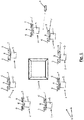
- Fig. 1 and 2 an intervention system 1 with several drones 2 is shown.
- the drones 2 are here arranged around an object 3 to be protected.
- the object 3 to be protected is protected against attacks with C-RAM targets 4 by means of the intervention system 1.
- a rocket 4 is shown here as an example for a C-RAM target 4.
- the intervention system 1 is also suitable for protecting the object 3 against attacks by third-party drones (not shown).
- the drones 2 each have an effector 5, the effector 5 being formed by an explosive charge arrangement 5.
- the drones 2 are designed as multicopters.
- the drones 2 accordingly have several propellers 6.
- the drones 2 are initially ready to take off or are already positioned around the object 3 to be protected while floating in a standby mode.
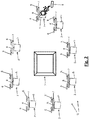
- the next positioned drone 2 of the intervention system 1 is steered to a pre-calculated trajectory of the target 4.
- the target 4 is fought by means of the explosive charge arrangement 5 (cf. Fig. 2 ).
- the drone 2 can preferably be on the flight path in front of the target 4 when fighting the target 4 or next to the target 4 when the target 4 is flying past.
- the drones 2 of the intervention system 1 are preferably controlled by means of a command-and-control system (not shown) remotely. In an alternative embodiment, the drones 2 can also be designed to be self-steering.
- the drones 2 also have various sensors 7, such as a TV camera, radar, lidar or IR sensors. These sensors 7 are arranged on a fuselage 8. When a target 4 is approaching, in particular the drone 2 closest to the predicted flight path of target 4 is accelerated in the direction of the flight path of target 4. With such a strong acceleration it can happen that the drones 2 with their propeller axes are directed essentially in the direction of flight. Here it is advantageous if the sensors 7 are also directed in the direction of flight of the drone 2.
- the sensors 7 are preferably aligned at an acute angle or parallel to the propeller axes.
- the sensors 7 can therefore preferably be pivoted in the direction of the propeller axes by means of corresponding joints.
- the fuselage 8 is inclined relative to the direction of flight.
- the sensors 7 are used in particular for final phase control of the drone 2 shortly before the target 4 flies past.
- the drones 2 hover in particular evenly distributed at such a maximum distance around the object 3 to be protected, so that the next-positioned drone 2 has enough time to reach the possible trajectory of the target 4.
- the distance between a drone 2 and its neighboring drones 2 is preferably less than 1 km, in particular less than 800 m, in particular approximately 600 m. It is possible here to arrange the drones 2 on a circle or a hemisphere with a diameter of 1.5 km around the object 3 to be protected.
- the drones 2 are not only arranged on a circular path, but also cover a spherical segment around the object 3 to be protected.
- the drones 2 can each be arranged at a distance of approximately 600 m, with eight drones 2 being distributed over the corresponding circle. With these eight drones 2, the object 3 with an area of 250,000 m 2 can be protected. To intercept a target 4, one of the drones 2 therefore only has to cover a distance of about 300 m.
- the drones 2 and the intervention system 1 have the advantage that the drones 2 can be steered and are inexpensive. Object protection, for example of buildings or vehicles, is made possible by using a network of drones 2.
- the explosive charge arrangement 5 is connected to the fuselage 8 preferably via a gimbal 9.
- the gimbal 9 is essentially arranged in the center of gravity of the drone 2 with a horizontal alignment of the drone 2.
- the Gimbal 9 can be formed by a cardanic suspension or mounting, that is to say mounting in two planes with bearings arranged at right angles to one another. This special arrangement and a balanced center of gravity make it possible for the explosive charge arrangement 5 to pivot about several axes.
- the explosive charge arrangement 5 is arranged on an underside of the fuselage 8 of the drone 2.
- the explosive charge arrangement 5 can either have a shaped charge 10, a projectile-forming charge, a fragment-forming charge 11 or a combination of these charges.
- the explosive charge arrangement 5 has a shaped charge 10 and a fragmentation charge 11.
- the explosive charge arrangement 5 is designed such that the shaped charge 10 and the fragmentation charge 11 can emerge in a lateral direction relative to the rotor axis. Because the hollow charge 10 and the fragmentation charge 11 act transversely to the direction of the rotor axes, targets 4 can be fought very well in flyby.
- the shaped charge 10 and the fragmentation charge 11 are arranged within a housing 12.
- the hollow charge 10 and the fragmentation charge 11 are each assigned a separate explosive 13, 14.
- the explosive 13 has a greater detonation speed than the explosive 14.
- Both explosives 13, 14 are ignited by means of a detonator (not shown) at the base of the hollow charge 10. Due to the different detonation speeds of the explosives 13, 14, the shaped charge jet (not shown) can exit completely before the fragmentation charge 11 detonates and exits. In this way an interaction between the two detonations can be avoided.
- the shaped charge 10 has a metal insert 15 in the form of a shaped charge cone 15.
- the shaped charge cone 15 preferably has copper or is made of copper.
- the axis of symmetry (not shown) of the shaped charge cone 15 is also oriented here in a lateral direction relative to the rotor axis.
- the housing 12 is in particular cylindrical, the gimbal 9 preferably being centered on a cover 16 is attached.
- the shaped charge 10 and the fragmentation charge 11 point towards the cylindrical wall 17 of the housing 12.
Abstract
Die Erfindung betrifft ein Interventionssystem (1) und ein Verfahren zur Abwehr von Drohungen (4) in Form von Raketen-, Artillerie- und Mörser- (RAM-)Drohungen (4) und/oder UAVs, wobei mittels des Interventionssystems (1) ein Objekt (3) vor RAM-Zielen (4) und/oder UAVs geschützt wird.Ein kostengünstiges Verfahren und ein kostengünstiges Interventionssystem (1) gegen RAM-Drohungen und/oder gegen feindliche UAVs / Drohnen sind dadurch bereitgestellt, dass mehrere Drohnen (2) des Interventionssystems (1) in einem Bereitschaftsmodus um das Objekt (3) angeordnet werden, wobei Drohnen (2) in Form von Multikoptern mit jeweils einem Effektor (5) in Form einer Sprengladungsanordnung (5) verwendet werden, wobei eine Flugbahn der Drohung (4) vorausberechnet wird und die zur Flugbahn nächst benachbarte Drohne (2) auf die Flugbahn oder nahe der Flugbahn der Drohung (4) gesteuert wird, wobei bei einer Annäherung der Drohung (2) an diese benachbarte Drohne (2) die Drohung (4) durch Zündung der Sprengladungsanordnung (5) bekämpft wird.The invention relates to an intervention system (1) and a method for repelling threats (4) in the form of rocket, artillery and mortar (RAM) threats (4) and / or UAVs, with the intervention system (1) being a Object (3) is protected from RAM targets (4) and / or UAVs. A cost-effective method and a cost-effective intervention system (1) against RAM threats and / or against enemy UAVs / drones are provided by the fact that several drones (2) of the intervention system (1) can be arranged around the object (3) in a standby mode, with drones (2) in the form of multicopters, each with an effector (5) in the form of an explosive charge arrangement (5) being used, with a trajectory of the threat (4 ) is calculated in advance and the drone (2) closest to the flight path is steered onto the flight path or near the flight path of the threat (4), with the threat (4) being carried out when the threat (2) approaches this neighboring drone (2) Ignition of the blast charge arrangement (5) is combated.
Description
Die Erfindung betrifft ein Interventionssystem zur Abwehr von Zielen in Form von RAM-Zielen und/oder UAVs mit den Merkmalen des Oberbegriffes des Patentanspruches 1. Ferner betrifft die Erfindung ein Verfahren zur Abwehr von RAM-Zielen und/oder UAVs mit den Merkmalen des Oberbegriffes des Patentanspruches.The invention relates to an intervention system for defense against targets in the form of RAM targets and / or UAVs with the features of the preamble of claim 1. Furthermore, the invention relates to a method for defense against RAM targets and / or UAVs with the features of the preamble of Claim.
Das Interventionssystem ist dazu geeignet, unbemannte Luftfahrzeuge in Form von sogenannten UAVs (Unmanned Areal Vehicles) zu bekämpfen, die ohne eine an Bord befindliche Besatzung durch einen Computer oder vom Boden über eine Fernsteuerung betrieben und navigiert werden können. Das Interventionssystem ist in der Lage, RAM-Ziele (RAM - Rocket, Artillery and Mortar) wie Raketen, Artillerie und Mörser-Geschosse zu bekämpfen. Solche Interventionssysteme werden auch als C-RAM-Systeme oder Counter-RAM-Systeme (Counter Rocket Artillery and Mortar) bezeichnet.The intervention system is suitable for fighting unmanned aerial vehicles in the form of so-called UAVs (Unmanned Areal Vehicles), which can be operated and navigated without a crew on board by a computer or from the ground via a remote control. The intervention system is able to fight RAM (Rocket, Artillery and Mortar) targets such as missiles, artillery and mortar shells. Such intervention systems are also known as C-RAM systems or Counter-RAM systems (Counter Rocket Artillery and Mortar).
Es ist bekannt, RAM-Ziele mit Raketen oder Maschinenkanonen zu bekämpfen. Raketen oder Maschinenkanonen sind teuer, insbesondere wenn sie in größeren Stückzahlen eingesetzt werden müssen.It is known to fight RAM targets with missiles or automatic cannons. Missiles or automatic cannons are expensive, especially if they have to be used in large numbers.
Aus der
Aus der
Aus der
Der Erfindung liegt daher die Aufgabe zugrunde, ein kostengünstiges Verfahren und ein kostengünstiges Interventionssystem gegen RAM-Ziele und/oder gegen feindliche UAVs / Drohnen bereitzustellen.The invention is therefore based on the object of providing a cost-effective method and a cost-effective intervention system against RAM targets and / or against enemy UAVs / drones.
Diese der Erfindung zugrunde liegende Aufgabe wird nun durch ein Interventionssystem und ein Verfahren mit den Merkmalen der unabhängigen Patentansprüche gelöst.This object on which the invention is based is now achieved by an intervention system and a method having the features of the independent claims.
Das erfindungsgemäße Interventionssystem weist mehrere UAVs bzw. Drohnen auf, welche jeweils mit einem Effektor zur Bekämpfung von C-RAM-Zielen und/oder UAVs ausgestattet sind, wobei die Drohnen in einem Bereitschaftsmodus um das Objekt angeordnet sind, wobei die Drohnen jeweils einen Effektor in Form einer Sprengladungsanordnung aufweisen, wobei die Drohnen als Multikopter ausgebildet sind. Dies ermöglicht eine kostengünstige Bekämpfung von C-RAM Zielen und UAVs.The intervention system according to the invention has several UAVs or drones, each of which is equipped with an effector to combat C-RAM targets and / or UAVs, the drones being arranged around the object in a standby mode, the drones each having an effector in Have the form of an explosive charge arrangement, the drones being designed as multicopters. This enables cost-effective combat against C-RAM targets and UAVs.
Das erfindungsgemäße Verfahren zeichnet sich dadurch aus, dass mehrere Drohnen des Interventionssystems in einem Bereitschaftsmodus um das Objekt angeordnet werden, wobei Drohnen in Form von Multikoptern mit jeweils einem Effektor in Form einer Sprengladungsanordnung verwendet werden, wobei eine Flugbahn des Ziels vorausberechnet wird und die zur Flugbahn nächst benachbarte Drohne auf die Flugbahn oder nahe der Flugbahn des Ziels gesteuert wird, wobei bei einer Annäherung des Ziels an diese benachbarte Drohne das Ziel durch Zündung der Sprengladungsanordnung bekämpft wird.The method according to the invention is characterized in that several drones of the intervention system are arranged around the object in a standby mode, with drones in the form of multicopters each with an effector in the form of an explosive charge arrangement being used, a trajectory of the target being calculated in advance and that of the trajectory next adjacent drone is steered onto the trajectory or close to the trajectory of the target, the target being fought by detonating the explosive charge arrangement when the target approaches this adjacent drone.
Eine sichere Zerstörung ergibt sich dadurch, dass ein Zünder des Ziels anvisiert wird. Dies hat ferner den Vorteil, dass die Trümmer kleinteilig sind und so wenig Schaden verursachen.A certain destruction results from the fact that a detonator of the target is sighted. This also has the advantage that the debris is divided into small pieces and thus causes little damage.
Das Interventionssystem ist bevorzugt geeignet zum Schutz von Objekten, wie Gebäuden oder Fahrzeugen. Auch sich langsam bewegende Objekte können gut durch Drohnen in Form von Multikoptern geschützt werden. Da die Drohnen beweglich sind können somit auch bewegliche Objekte geschützt werden. Die Drohnen sind dabei zunächst startbereit oder bereits schwebend in einem Bereitschaftsmodus um das zu schützende Objekt angeordnet. Im Bereitschaftsmodus schweben die Drohnen insbesondere gleichverteilt und mit einem derartigen maximalen Abstand so um das zu schützende Objekt, dass die nächstpositionierte Drohne genügend Zeit hat, um die mögliche Flugbahn des Ziels erreichen zu können. Beispielsweise kann mit acht Drohnen ein Objekt mit einer Fläche von 250000 m2 geschützt werden. Hierzu sind die Drohnen gleichverteilt auf einer Kreisbahn mit einem Radius von 750 m um das Objekt herum angeordnet. Daraus ergibt sich ein Abstand von knapp unter 600 m zwischen den einzelnen Drohnen. Zum Abfangen des Ziels muss eine Drohne daher nur ca. 300 m Wegstrecke zurücklegen. Insbesondere sind die Drohnen um das Objekt mit einem Radius von weniger als 1 km angeordnet.The intervention system is preferably suitable for protecting objects such as buildings or vehicles. Even slowly moving objects can be well protected by drones in the form of multicopters. Since the drones are mobile, moving objects can also be protected. The drones are initially ready to start or are already floating around the object to be protected in a standby mode. In the standby mode, the drones hover in particular evenly distributed and at such a maximum distance around the object to be protected that the next-positioned drone has enough time to be able to reach the possible trajectory of the target. For example, eight drones can protect an object with an area of 250,000 m 2 . For this purpose, the drones are evenly distributed on a circular path with a radius of 750 m around the object. This results in a distance of just under 600 m between the individual drones. To intercept the target, a drone therefore only has to cover a distance of approx. 300 m. In particular, the drones are arranged around the object with a radius of less than 1 km.
Die Drohnen weisen im Bereitschaftsmodus zur jeweils benachbarten Drohne einen Abstand von weniger als 1000m, insbesondere von weniger als 800 m, vorzugsweise von weniger als 600 m auf, wodurch die Drohnen nur eine kurze Distanz zur Flugbahn des Ziels zurücklegen müssen.In standby mode, the drones are at a distance of less than 1000 m, in particular less than 800 m, to the neighboring drone, preferably less than 600 m, which means that the drones only have to travel a short distance from the flight path of the target.
Die Drohnen sind im Bereitschaftsmodus auf einer Kreisbahn oder auf einem Kugelsegment um das Objekt angeordnet, damit das Objekt engmaschig geschützt ist. Hierbei ist es von besonderem Vorteil, dass die Multikopter auf der Stelle schweben können und damit stets die optimale Verteidigungsposition einnehmen können.In standby mode, the drones are arranged on a circular path or on a spherical segment around the object so that the object is closely protected. It is particularly advantageous that the multicopters can hover on the spot and thus always assume the optimal defensive position.
Die Sprengladungsanordnung kann insbesondere eine Hohlladung aufweisen. Die Sprengladungsanordnung kann alternativ oder zusätzlich eine Splitterladung aufweisen. Als Effektor kann eine Sprengladungsanordnung mit nur einer Hohlladung oder nur mit einer Splitterladung verwendet werden. Die Sprengladungsanordnung weist in bevorzugter Ausgestaltung sowohl eine Hohlladung als auch Splitterladung auf. Durch die Sprengladungsanordnung kann entweder eine Hohlladung, eine projektilbildende Ladung, eine splitterbildende Ladung oder eine Kombination dieser Ladungen ausgestoßen werden.The explosive charge arrangement can in particular have a shaped charge. The explosive charge arrangement can alternatively or additionally have a fragmentation charge. An explosive charge arrangement with only one shaped charge or only one fragment charge can be used as the effector. In a preferred embodiment, the explosive charge arrangement has both a shaped charge and a fragment charge. Either a shaped charge, a projectile-forming charge, a fragment-forming charge or a combination of these charges can be ejected through the explosive charge arrangement.
Die Drohnen weisen jeweils einen Rumpf und ein Gimbal auf, wobei die Sprengladungsanordnung mittels des Gimbals mit dem Rumpf der Drohne verbunden ist. Hierdurch kann die Sprengladungsanordnung gut auf das Ziel im Vorbeiflug ausgerichtet werden.The drones each have a fuselage and a gimbal, the explosive charge arrangement being connected to the fuselage of the drone by means of the gimbal. In this way, the explosive charge arrangement can be well aligned with the target in the flyby.
Bei Anflug eines Ziels wird die Flugbahn des Ziels vorausberechnet und die nächstpositionierte Drohne des Interventionssystems wird zur Flugbahn des Ziels gesteuert. Vorzugsweise werden die Drohnen des Interventionssystems mittels eines Command und Control-Systems ferngesteuert. Die Drohnen können alternativ aber auch selbstlenkend ausgestaltet sein.When approaching a target, the flight path of the target is calculated in advance and the next positioned drone of the intervention system is steered towards the flight path of the target. The drones of the intervention system are preferably remote-controlled by means of a command and control system. Alternatively, the drones can also be designed to be self-steering.
Die Drohne kann dann auf die Flugbahn oder nahe an die Flugbahn gesteuert werden. Bei Annäherung des Ziels an der nächstpositionierten Drohne wird mittels der Sprengladungsanordnung, d.h. mittels des Effektors, das Ziel bekämpft. Dabei kann sich die Drohne bevorzugt auf der Flugbahn vor dem Ziel befinden oder neben dem Ziel bei dem Vorbeiflug des Ziels.The drone can then be steered onto or close to the flight path. When the target approaches the next positioned drone, the target is set by means of the explosive charge arrangement, ie by means of the effector fights. The drone can preferably be on the flight path in front of the target or next to the target when the target is flying past.
Bei Verwendung einer projektil- und splitterbildenden Ladung wird bevorzugt gezielt ein Zünder des Ziels anvisiert, wobei der Zünder des Ziels in der Regel am Kopf des RAM-Ziels angeordnet ist. Hierbei wird die Drohne bevorzugt auf der Flugbahn des Ziels positioniert.When using a projectile and fragment-forming charge, a detonator of the target is preferably targeted in a targeted manner, the detonator of the target generally being arranged at the head of the RAM target. The drone is preferably positioned on the trajectory of the target.
Die Drohnen weisen jeweils mindestens einen Sensor zur Endphasenlenkung der Drohne auf. Die Drohnen verfügen bevorzugt über mehrere, verschiedene Sensoren wie beispielsweise TV-Kameras, Radar-, Lidar- und/oder IR-Sensoren. Diese Sensoren sind dabei am Rumpf der Drohne im schwebenden Zustand der Drohne nach oben zum Himmel gerichtet, so dass bei einem schnellen Flug mit einem geneigten Rumpf die Sensorik in Flugrichtung auf das Ziel gerichtet ist. Der mindestens eine Sensor ist in Richtung einer Rotorachse oder spitzwinklig zur Rotorachse der Drohne ausgerichtet, so dass auch bei einer schnellen Beschleunigung das Ziel mit dem Sensor oder den Sensoren erfasst werden können. Die Sensoren der Drohne dienen insbesondere zur Endphasenlenkung beim Vorbeiflug des Ziels.The drones each have at least one sensor for final phase control of the drone. The drones preferably have several different sensors such as TV cameras, radar, lidar and / or IR sensors. These sensors are directed upwards towards the sky on the drone's fuselage when the drone is hovering, so that during a fast flight with a tilted fuselage, the sensors are directed towards the target in the direction of flight. The at least one sensor is oriented in the direction of a rotor axis or at an acute angle to the rotor axis of the drone, so that the target can be detected with the sensor or sensors even during rapid acceleration. The drone's sensors are used in particular for final phase control when the target flies by.
Es gibt nun verschiedene Möglichkeiten, das Interventionssystem und das Verfahren auszugestalten und weiterzubilden. Hierfür darf zunächst auf die den unabhängigen Patentansprüchen nachgeordneten Patentansprüche verwiesen werden. Im Folgenden werden bevorzugte Ausgestaltungen des Verfahrens des Interventionssystems anhand der Zeichnung und der dazugehörigen Beschreibung näher erläutert. In der Zeichnung zeigt:
- Fig. 1
- in einer schematischen Draufsicht ein Interventionssystem mit mehreren Drohnen, wobei die Drohen um ein Objekt angeordnet sind, das von einem C-RAM-Ziel angegriffen wird,
- Fig. 2
- in einer schematischen Draufsicht das Interventionssystem, wobei das C-RAM-Ziel mittels einer der Drohnen bekämpft wird,
- Fig. 3
- in einer schematischen, teilweise geschnittenen Darstellung eine Drohne mit einer Sprengladungsanordnung, sowie
- Fig. 1
- in a schematic top view an intervention system with several drones, wherein the drones are arranged around an object that is attacked by a C-RAM target,
- Fig. 2
- a schematic top view of the intervention system, with the C-RAM target being fought using one of the drones,
- Fig. 3
- in a schematic, partially sectioned representation, a drone with an explosive charge arrangement, and
In
Die Drohnen 2 sind zunächst startbereit oder bereits schwebend in einem Bereitschaftsmodus um das zu schützende Objekt 3 positioniert. Beim Anflug eines C-RAM-Ziels 4 oder einer Drohne (nicht dargestellt) wird die nächstpositionierte Drohne 2 des Interventionssystems 1 zu einer vorausberechneten Flugbahn des Ziels 4 gesteuert. Bei Annäherung des Ziels 4 an die Drohne 2 wird dann mittels der Sprengladungsanordnung 5 das Ziel 4 bekämpft (vgl.
Die Drohnen 2 verfügen ferner über verschiedene Sensoren 7, wie beispielsweise eine TV-Kamera, Radar-, Lidar- oder IR-Sensoren. Diese Sensoren 7 sind an einem Rumpf 8 angeordnet. Wenn ein Ziel 4 im Anflug ist, wird insbesondere die der vorausberechneten Flugbahn des Ziels 4 nächst benachbarte Drohne 2 in Richtung der Flugbahn des Ziels 4 beschleunigt. Bei einer solchen starken Beschleunigung kann es vorkommen, dass die Drohnen 2 mit ihren Propellerachsen im Wesentlichen in Flugrichtung gerichtet sind. Hier ist es vorteilhaft, wenn die Sensoren 7 ebenfalls in Flugrichtung der Drohne 2 gerichtet sind. Die Sensoren 7 sind dabei vorzugsweise spitzwinklig oder parallel zu den Propellerachsen ausgerichtet. Vorzugsweise sind daher die Sensoren 7 mittels entsprechender Gelenke in Richtung der Propellerachsen schwenkbar. Bei diesem schnellen Flug der Drohnen 2 ist der Rumpf 8 relativ zur Flugrichtung geneigt. Die Sensoren 7 dienen insbesondere der Endphasenlenkung der Drohne 2 kurz vor dem Vorbeiflug des Ziels 4.The
Im Bereitschaftsmodus schweben die Drohnen 2 insbesondere gleichverteilt mit einem derartigen maximalen Abstand um das zu schützende Objekt 3, so dass die nächstpositionierte Drohne 2 genug Zeit hat, um die mögliche Flugbahn des Ziels 4 zu erreichen. Vorzugsweise beträgt der Abstand einer Drohne 2 zu seinen benachbarten Drohnen 2 weniger als 1 km, insbesondere weniger von 800 m, insbesondere etwa 600 m. Es ist hierbei möglich, die Drohnen 2 auf einem Kreis oder einer Halbkugel mit einem Durchmesser von 1,5 km um das zu schützende Objekt 3 anzuordnen. Vorzugsweise sind die Drohnen 2 dabei nicht nur auf einer Kreisbahn angeordnet, sondern decken ein Kugelsegment um das zu schützende Objekt 3 ab. Beispielsweise können auf einem Kreis mit einem Durchmesser von 1,5 km bzw. Radius von 750m die Drohnen 2 jeweils im Abstand von ca. 600 m angeordnet werden, wobei hierbei acht Drohnen 2 auf dem entsprechenden Kreis verteilt sind. Mit diesen acht Drohnen 2 kann das Objekt 3 mit einer Fläche von 250.000 m2 geschützt werden. Zum Abfangen eines Ziels 4 muss eine der Drohnen 2 daher nur ca. 300 m Wegstrecke zurücklegen.In the standby mode, the
Die Drohnen 2 und das Interventionssystem 1 haben den Vorteil, dass die Drohnen 2 lenkbar sind und kostengünstig sind. Es ist ein Objektschutz, beispielsweise von Gebäuden oder Fahrzeugen, durch Einsatz eines Verbunds von Drohnen 2 ermöglicht.The
Im Folgenden darf auf die
Die Sprengladungsanordnung 5 kann entweder eine Hohlladung 10, eine projektilbildende Ladung, eine splitterbildende Ladung 11 oder eine Kombination dieser Ladungen aufweisen. Bei der hier beschriebenen Ausgestaltung weist die Sprengladungsanordnung 5 eine Hohlladung 10 und eine Splitterladung 11 auf. Die Sprengladungsanordnung 5 ist derart ausgebildet, dass die Hohlladung 10 und die Splitterladung 11 in einer seitlichen Richtung relativ zur Rotorachse austreten können. Dadurch, dass die Hohlladung 10 und die Splitterladung 11 quer zur Richtung der Rotorachsen wirken, können hierdurch sehr gut Ziele 4 im Vorbeiflug bekämpft werden.The
Die Hohlladung 10 und die Splitterladung 11 sind innerhalb eines Gehäuses 12 angeordnet. Der Hohlladung 10 und der Splitterladung 11 ist jeweils ein separater Sprengstoff 13, 14 zugeordnet. Der Sprengstoff 13 weist eine größere Detonationsgeschwindigkeit als der Sprengstoff 14 auf. Beide Sprengstoffe 13, 14 werden mittels eines nicht dargestellten Zünders am Fuß der Hohlladung 10 gezündet. Durch die unterschiedlichen Detonationsgeschwindigkeiten der Sprengstoffe 13, 14 kann der Hohlladungsstrahl (nicht dargestellt) vollkommen austreten, bevor die Splitterladung 11 detoniert und austritt. Dadurch kann eine Wechselwirkung zwischen den beiden Detonationen vermieden werden.The shaped
Die Hohlladung 10 weist eine Metalleinlage 15 in Form eines Hohlladungskegels 15 auf. Der Hohlladungskegel 15 weist vorzugsweise Kupfer auf bzw. ist aus Kupfer hergestellt. Die Symmetrieachse (nicht dargestellt) des Hohlladungskegels 15 ist hier ebenfalls in seitlicher Richtung relativ zur Rotorachse ausgerichtet. Das Gehäuse 12 ist insbesondere zylindrisch ausgebildet, wobei das Gimbal 9 an einem Deckel 16 vorzugsweise mittig befestigt ist. Die Hohlladung 10 und die Splitterladung 11 weisen zur zylindrischen Wandung 17 des Gehäuses 12.The shaped
- 11
- InterventionssystemIntervention system
- 22
- Drohnedrone
- 33
- zu schützendes Objektobject to be protected
- 44th
- Ziel / C-RAM-Ziel / RaketeTarget / C-RAM target / missile
- 55
- Effektor bzw. SprengladungsanordnungEffector or explosive charge arrangement
- 66th
- Propellerpropeller
- 77th
- Sensorsensor
- 88th
- Rumpfhull
- 99
- GimbalGimbal
- 1010
- HohlladungShaped charge
- 1111
- SplitterladungFragmentation charge
- 1212
- Gehäusecasing
- 1313
- Sprengstoff der HohlladungExplosives of the shaped charge
- 1414th
- Sprengstoff der SplitterladungExplosives from the fragmentation charge
- 1515th
- Metalleinlage bzw. HohlladungskegelMetal insert or shaped charge cone
- 1616
- Deckelcover
- 1717th
- zylindrische Wandungcylindrical wall
- 1818th
- KopfendeHead end
- 1919th
- SplitterfragmenteShard Fragments
- 2020th
- DurchgangPassage
- 2121st
- DurchgangPassage
- 2222nd
- Gehäusecasing
Claims (10)
Applications Claiming Priority (1)
| Application Number | Priority Date | Filing Date | Title |
|---|---|---|---|
| DE102019109360.0A DE102019109360A1 (en) | 2019-04-09 | 2019-04-09 | Invention system for defense against RAM targets and / or UAVs as well as methods for defense against RAM targets and / or UAVs |
Publications (1)
| Publication Number | Publication Date |
|---|---|
| EP3722736A1 true EP3722736A1 (en) | 2020-10-14 |
Family
ID=69902990
Family Applications (1)
| Application Number | Title | Priority Date | Filing Date |
|---|---|---|---|
| EP20160480.8A Pending EP3722736A1 (en) | 2019-04-09 | 2020-03-02 | Inventional system for defence of ram targets and / or uavs and method for defence of ram targets and / or uavs |
Country Status (2)
| Country | Link |
|---|---|
| EP (1) | EP3722736A1 (en) |
| DE (1) | DE102019109360A1 (en) |
Families Citing this family (1)
| Publication number | Priority date | Publication date | Assignee | Title |
|---|---|---|---|---|
| DE102020003043A1 (en) | 2020-05-20 | 2021-11-25 | SDT Industrial Technology UG (haftungsbeschränkt) | The airspace protection system against the objects in flight |
Citations (6)
| Publication number | Priority date | Publication date | Assignee | Title |
|---|---|---|---|---|
| DE2519507A1 (en) | 1975-05-02 | 1976-11-18 | Messerschmitt Boelkow Blohm | Warhead for attacking aerial targets - with target seeking guidance system and transverse hollow charges aligned on the target |
| DE3438305A1 (en) | 1984-10-19 | 1986-04-24 | Diehl GmbH & Co, 8500 Nürnberg | UNMANNED AIRCRAFT FOR COMBATING GROUND TARGETS |
| GB2356995A (en) * | 1999-11-30 | 2001-06-06 | Roke Manor Research | Autonomous defence systems |
| KR20170095056A (en) * | 2016-02-12 | 2017-08-22 | 전준필 | Security system using a drone having a plurality of rotor |
| DE102015008255B4 (en) | 2015-06-26 | 2017-10-19 | Diehl Defence Gmbh & Co. Kg | Defense drone to ward off a small drone |
| EP3410057A1 (en) * | 2017-05-29 | 2018-12-05 | Plasan Sasa Ltd. | Drone-based active protection system |
Family Cites Families (6)
| Publication number | Priority date | Publication date | Assignee | Title |
|---|---|---|---|---|
| AU2002364006A1 (en) * | 2001-12-21 | 2003-07-30 | David J. Arlton | Micro-rotocraft surveillance system |
| US9026272B2 (en) * | 2007-12-14 | 2015-05-05 | The Boeing Company | Methods for autonomous tracking and surveillance |
| WO2016205415A1 (en) * | 2015-06-15 | 2016-12-22 | ImageKeeper LLC | Unmanned aerial vehicle management |
| US20180164080A1 (en) * | 2016-08-22 | 2018-06-14 | Richard Chi-Hsueh | Land and air defense system having drones |
| EP3625125A1 (en) * | 2017-05-17 | 2020-03-25 | AeroVironment, Inc. | System and method for interception and countering unmanned aerial vehicles (uavs) |
| US10495421B2 (en) * | 2017-08-25 | 2019-12-03 | Aurora Flight Sciences Corporation | Aerial vehicle interception system |
-
2019
- 2019-04-09 DE DE102019109360.0A patent/DE102019109360A1/en active Pending
-
2020
- 2020-03-02 EP EP20160480.8A patent/EP3722736A1/en active Pending
Patent Citations (6)
| Publication number | Priority date | Publication date | Assignee | Title |
|---|---|---|---|---|
| DE2519507A1 (en) | 1975-05-02 | 1976-11-18 | Messerschmitt Boelkow Blohm | Warhead for attacking aerial targets - with target seeking guidance system and transverse hollow charges aligned on the target |
| DE3438305A1 (en) | 1984-10-19 | 1986-04-24 | Diehl GmbH & Co, 8500 Nürnberg | UNMANNED AIRCRAFT FOR COMBATING GROUND TARGETS |
| GB2356995A (en) * | 1999-11-30 | 2001-06-06 | Roke Manor Research | Autonomous defence systems |
| DE102015008255B4 (en) | 2015-06-26 | 2017-10-19 | Diehl Defence Gmbh & Co. Kg | Defense drone to ward off a small drone |
| KR20170095056A (en) * | 2016-02-12 | 2017-08-22 | 전준필 | Security system using a drone having a plurality of rotor |
| EP3410057A1 (en) * | 2017-05-29 | 2018-12-05 | Plasan Sasa Ltd. | Drone-based active protection system |
Also Published As
| Publication number | Publication date |
|---|---|
| DE102019109360A1 (en) | 2020-10-15 |
Similar Documents
| Publication | Publication Date | Title |
|---|---|---|
| DE4426014B4 (en) | System for protecting a target against missiles | |
| DE69628759T2 (en) | METHOD FOR INCREASING AIR DEFENSE MEETING PROBABILITY AND WEAPON DESIGNED AFTER THIS | |
| EP3109586A1 (en) | Projectile for intercepting a small drone | |
| EP3722736A1 (en) | Inventional system for defence of ram targets and / or uavs and method for defence of ram targets and / or uavs | |
| DE2518593C3 (en) | Mortar projectile | |
| DE102015015938A1 (en) | Autonomous, unmanned aerial vehicles to escort, escort and secure lulled vehicles such as fixed wing and rotorcraft | |
| EP2594891B1 (en) | Method for defence against an approaching ballistic rocket and interception system | |
| EP0249678B1 (en) | Ammunition, especially for fighting targets provided with a reactive armour | |
| EP0708305B1 (en) | Method for protecting radiation emitting devices from missiles, in particular infrared radiation emitting devices such as ships | |
| DE3013405A1 (en) | METHOD FOR AVOIDING MESSAGE FROM LAUNCHERS FOR BALLISTIC missiles | |
| DE2522927C2 (en) | SYSTEM FOR REPLACEMENT, DISTRACTION AND DESTRUCTION OF ARMS | |
| DE4029898A1 (en) | Mine-laying system with separately deployed sensors and warheads - covers hostile teritory with distributed sensor units returning signals to programmed warhead deployment and detonation system | |
| EP3376154B1 (en) | Method for protecting a cruise missile | |
| EP1612504B1 (en) | Warhead for ordnance ammunition | |
| DE102011089584B4 (en) | Weapon system, in particular method for effective control of ship targets | |
| EP0187900B1 (en) | Pilotless aircraft for fighting ground targets | |
| DE3529897C2 (en) | ||
| DE3421140C2 (en) | ||
| DE19540252C2 (en) | Procedure for guiding submunitions into a target and carrier therefor | |
| DE3527522A1 (en) | METHOD AND USE OF END-PHASE CORRECTED SUBMUNITION FOR FIGHTING ARMORED SUBSTANCES | |
| WO2020164869A1 (en) | Method for combating aerial targets by means of guided missiles | |
| DE2815206C2 (en) | Procedure, guided missile and weapon system for combating ground targets | |
| DE4034618A1 (en) | MINE | |
| DE3911576C2 (en) | ||
| DE102017002262B4 (en) | Method of defending a submarine against attack by a submerged explosive device |
Legal Events
| Date | Code | Title | Description |
|---|---|---|---|
| PUAI | Public reference made under article 153(3) epc to a published international application that has entered the european phase |
Free format text: ORIGINAL CODE: 0009012 |
|
| STAA | Information on the status of an ep patent application or granted ep patent |
Free format text: STATUS: THE APPLICATION HAS BEEN PUBLISHED |
|
| AK | Designated contracting states |
Kind code of ref document: A1 Designated state(s): AL AT BE BG CH CY CZ DE DK EE ES FI FR GB GR HR HU IE IS IT LI LT LU LV MC MK MT NL NO PL PT RO RS SE SI SK SM TR |
|
| AX | Request for extension of the european patent |
Extension state: BA ME |
|
| STAA | Information on the status of an ep patent application or granted ep patent |
Free format text: STATUS: REQUEST FOR EXAMINATION WAS MADE |
|
| 17P | Request for examination filed |
Effective date: 20210414 |
|
| RBV | Designated contracting states (corrected) |
Designated state(s): AL AT BE BG CH CY CZ DE DK EE ES FI FR GB GR HR HU IE IS IT LI LT LU LV MC MK MT NL NO PL PT RO RS SE SI SK SM TR |
|
| STAA | Information on the status of an ep patent application or granted ep patent |
Free format text: STATUS: EXAMINATION IS IN PROGRESS |
|
| 17Q | First examination report despatched |
Effective date: 20230609 |