EP3722684B1 - Klimaanlageninnenraumeinheit - Google Patents
Klimaanlageninnenraumeinheit Download PDFInfo
- Publication number
- EP3722684B1 EP3722684B1 EP19778419.2A EP19778419A EP3722684B1 EP 3722684 B1 EP3722684 B1 EP 3722684B1 EP 19778419 A EP19778419 A EP 19778419A EP 3722684 B1 EP3722684 B1 EP 3722684B1
- Authority
- EP
- European Patent Office
- Prior art keywords
- panel
- opening
- indoor unit
- closing door
- air conditioner
- Prior art date
- Legal status (The legal status is an assumption and is not a legal conclusion. Google has not performed a legal analysis and makes no representation as to the accuracy of the status listed.)
- Active
Links
Images








Classifications
-
- F—MECHANICAL ENGINEERING; LIGHTING; HEATING; WEAPONS; BLASTING
- F24—HEATING; RANGES; VENTILATING
- F24F—AIR-CONDITIONING; AIR-HUMIDIFICATION; VENTILATION; USE OF AIR CURRENTS FOR SCREENING
- F24F1/00—Room units for air-conditioning, e.g. separate or self-contained units or units receiving primary air from a central station
- F24F1/0007—Indoor units, e.g. fan coil units
- F24F1/0011—Indoor units, e.g. fan coil units characterised by air outlets
- F24F1/0014—Indoor units, e.g. fan coil units characterised by air outlets having two or more outlet openings
-
- F—MECHANICAL ENGINEERING; LIGHTING; HEATING; WEAPONS; BLASTING
- F24—HEATING; RANGES; VENTILATING
- F24F—AIR-CONDITIONING; AIR-HUMIDIFICATION; VENTILATION; USE OF AIR CURRENTS FOR SCREENING
- F24F13/00—Details common to, or for air-conditioning, air-humidification, ventilation or use of air currents for screening
- F24F13/20—Casings or covers
-
- F—MECHANICAL ENGINEERING; LIGHTING; HEATING; WEAPONS; BLASTING
- F24—HEATING; RANGES; VENTILATING
- F24F—AIR-CONDITIONING; AIR-HUMIDIFICATION; VENTILATION; USE OF AIR CURRENTS FOR SCREENING
- F24F1/00—Room units for air-conditioning, e.g. separate or self-contained units or units receiving primary air from a central station
- F24F1/0007—Indoor units, e.g. fan coil units
-
- F—MECHANICAL ENGINEERING; LIGHTING; HEATING; WEAPONS; BLASTING
- F24—HEATING; RANGES; VENTILATING
- F24F—AIR-CONDITIONING; AIR-HUMIDIFICATION; VENTILATION; USE OF AIR CURRENTS FOR SCREENING
- F24F13/00—Details common to, or for air-conditioning, air-humidification, ventilation or use of air currents for screening
- F24F13/02—Ducting arrangements
- F24F13/06—Outlets for directing or distributing air into rooms or spaces, e.g. ceiling air diffuser
-
- F—MECHANICAL ENGINEERING; LIGHTING; HEATING; WEAPONS; BLASTING
- F24—HEATING; RANGES; VENTILATING
- F24F—AIR-CONDITIONING; AIR-HUMIDIFICATION; VENTILATION; USE OF AIR CURRENTS FOR SCREENING
- F24F13/00—Details common to, or for air-conditioning, air-humidification, ventilation or use of air currents for screening
- F24F13/08—Air-flow control members, e.g. louvres, grilles, flaps or guide plates
- F24F13/10—Air-flow control members, e.g. louvres, grilles, flaps or guide plates movable, e.g. dampers
- F24F13/14—Air-flow control members, e.g. louvres, grilles, flaps or guide plates movable, e.g. dampers built up of tilting members, e.g. louvre
- F24F13/1426—Air-flow control members, e.g. louvres, grilles, flaps or guide plates movable, e.g. dampers built up of tilting members, e.g. louvre characterised by actuating means
-
- F—MECHANICAL ENGINEERING; LIGHTING; HEATING; WEAPONS; BLASTING
- F24—HEATING; RANGES; VENTILATING
- F24F—AIR-CONDITIONING; AIR-HUMIDIFICATION; VENTILATION; USE OF AIR CURRENTS FOR SCREENING
- F24F13/00—Details common to, or for air-conditioning, air-humidification, ventilation or use of air currents for screening
- F24F13/08—Air-flow control members, e.g. louvres, grilles, flaps or guide plates
- F24F13/10—Air-flow control members, e.g. louvres, grilles, flaps or guide plates movable, e.g. dampers
- F24F13/14—Air-flow control members, e.g. louvres, grilles, flaps or guide plates movable, e.g. dampers built up of tilting members, e.g. louvre
- F24F13/1486—Air-flow control members, e.g. louvres, grilles, flaps or guide plates movable, e.g. dampers built up of tilting members, e.g. louvre characterised by bearings, pivots or hinges
-
- F—MECHANICAL ENGINEERING; LIGHTING; HEATING; WEAPONS; BLASTING
- F24—HEATING; RANGES; VENTILATING
- F24F—AIR-CONDITIONING; AIR-HUMIDIFICATION; VENTILATION; USE OF AIR CURRENTS FOR SCREENING
- F24F13/00—Details common to, or for air-conditioning, air-humidification, ventilation or use of air currents for screening
- F24F13/08—Air-flow control members, e.g. louvres, grilles, flaps or guide plates
- F24F13/10—Air-flow control members, e.g. louvres, grilles, flaps or guide plates movable, e.g. dampers
- F24F13/14—Air-flow control members, e.g. louvres, grilles, flaps or guide plates movable, e.g. dampers built up of tilting members, e.g. louvre
- F24F13/1426—Air-flow control members, e.g. louvres, grilles, flaps or guide plates movable, e.g. dampers built up of tilting members, e.g. louvre characterised by actuating means
- F24F2013/1446—Air-flow control members, e.g. louvres, grilles, flaps or guide plates movable, e.g. dampers built up of tilting members, e.g. louvre characterised by actuating means with gearings
Definitions
- the present invention relates to the field of air handling equipment, and in particular to an air conditioner indoor unit.
- the front panel of the panel component is mostly an integrally formed part which requires a large injection mold and a resulting high cost in the production process. Also, the front panel requires a long time for injection molding, which affects the production efficiency of the panel component. Moreover, the front panel is subject to a large amount of deformation and a high scrap rate.
- the opening and closing door used for opening and closing the air outlet on the panel component in the air conditioner indoor unit is not stable enough, so the reliability of the air conditioner indoor unit is affected to some extent. At the same time, the single ventilation type of air conditioner indoor unit cannot meet the user's demands
- US 2018/209668 A1 discloses an air conditioner indoor unit according to the preamble of claim 1.
- an objective of the present invention is to provide an air conditioner indoor unit, which has a low manufacturing cost of the panel component, a high production efficiency, a high yield, and a stable operation of the opening and closing door, thus improving the reliability of the air conditioner indoor unit and realizing different ventilation effects, so as to satisfy the user's demands to a certain extent.
- An air conditioner indoor unit includes: a back plate component; a top cover component, a part of the top cover component being connected to a top wall of the back plate component; a panel component.
- the panel component includes: a first panel, a top end of the first panel is connected to another part of the top cover component, the first panel being arranged in front of the back plate component and connected to the back plate component, the first panel being provided with a first air outlet and a second air outlet arranged in sequence in an up and down direction; a second panel disposed below the first panel, and connected to a lower end of the first panel and the back plate component, respectively, and the second panel and the first panel being independently processed and molded; an opening and closing door mounting plate disposed at the rear of the first panel, and provided with a guiding groove; an opening and closing door arranged between the first panel and the opening and closing door mounting plate, the opening and closing door being movable relative to the opening and closing door mounting plate so as to open or close the first air outlet, a guiding post being arranged
- the size and cost of the required mold for manufacturing the panel component can be reduced to some extent, and thereby reduce the cooling and solidification time required for injection molding of panel component, improving the production efficiency of the panel component.
- the problem of large deformation due to the large size of the first panel and the second panel can be avoided to some extent, thus improving the yield of the first panel and the second panel.
- the first air outlet and the second air outlet are arranged in the first panel in the up and down direction, which is favorable to achieve different ventilation effect, and can meet the user's demands to a certain extent. It can improve the ventilation efficiency of the air conditioner indoor unit, and can also expand the ventilation range of the air conditioner indoor unit.
- the opening and closing door is movable relative to the opening and closing door mounting plate so as to open or close the first air outlet, and at the same time, a guiding groove is arranged on the opening and closing door mounting plate, and a guiding post is arranged on the opening and closing door. And the guiding post is adapted to extend into the guiding groove and is slidable relative to the guiding groove.
- the air conditioner indoor unit can be sealed to prevent particles such as dust in the room from entering the interior of the air conditioner indoor unit through the first air outlet.
- the engaging structure between the opening and closing door and the opening and closing door mounting plate can be made stronger, the operation of the opening and closing door can be more stable, the reliability of the panel component can be improved, and the reliability of the air conditioner indoor unit can be improved.
- At least a portion of the guiding groove extends obliquely downwards in a direction of the first panel, and the opening and closing door closes the first air outlet when the guiding post slides to an inclined portion of the guiding groove.
- the air conditioner indoor unit further includes a limiting connector, wherein one end of the limiting connector is slidably disposed to the opening and closing door mounting plate, and the other end of the limiting connector is rotatably disposed to the opening and closing door so that the limiting connector is configured to drive the opening and closing door to move.
- the air conditioner indoor unit further includes a driving mechanism, wherein the driving mechanism is connected to the limiting connector to drive the limiting connector to slide, so as to drive the opening and closing door to move.
- the driving mechanism includes: an actuator disposed to the opening and closing door mounting plate; a drive gear connected to the actuator and driven to rotate by the actuator; a rack connected to the limiting connector, and engaged with the driving gear to drive the limiting connector to slide.
- a side of the first panel facing the back plate component is provided with an engaging hook
- the back plate component is provided with an engaging buckle
- the engaging hook is configured to extend into the engaging buckle
- the engaging hook comprises a horizontal extending section and a vertical extending section, one end of the horizontal extending section is disposed to the first panel, the other end of the horizontal extending section is connected to an upper end of the vertical extending section, and a lower end of the vertical extending section is configured to extend into the engaging buckle.
- the engaging buckle is configured as a hollow structure.
- a top of a side of the first panel facing the back plate component is provided with an extension extending towards the back plate component, a lower end of the extension is provided with a positioning post, a top of the back plate component is provided with a positioning hole, and the positioning post is configured to extend into the positioning hole.
- the extension is provided with a first engaging hole
- the back plate component is provided with a second engaging hole
- the second engaging hole is disposed opposite to the first engaging hole.
- the air conditioner indoor unit further comprises a first connector, and the first connector passes through the first engaging hole and the second engaging hole to connect the first panel with the back plate component.
- a bottom of a side of the first panel facing the back plate component is provided with a positioning pin extending towards the back plate component
- the back plate component is provided with a positioning receptacle
- the positioning pin is configured to be inserted into the positioning receptacle.
- the first panel is provided with a third engaging hole
- the third engaging hole is disposed adjacent to the positioning pin
- the back plate component is provided with a fourth engaging hole
- the fourth engaging hole is disposed opposite to the third engaging hole.
- the air conditioner indoor unit further comprises a second connector, and the second connector passes through the third engaging hole and the fourth engaging hole so as to connect the first panel with the back plate component.
- the panel component further comprises an opening and closing element, and the opening and closing element is configured to move back and forth to open or close the second air outlet, and when the opening and closing element moves forwards to be in the front of the second air outlet, the opening and closing door opens the second air outlet.
- a top of the first panel is provided with a plurality of first reinforcing ribs spaced apart from one another.
- an appearance surface of the first panel is configured as a curved surface.
- An opening and closing door assembly 100 for an indoor unit air of conditioner based on an embodiment of the present disclosure is described below with reference to the drawings, and the air conditioner indoor unit can be wall-mounted unit or cabinet.
- an indoor unit 100 of air conditioner based on an embodiment of the present invention includes a back plate component 1, a top cover component 5, and a panel component 2.
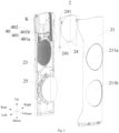
- the panel component 2 includes a first panel 21, a second panel 22, an opening and closing door mounting plate 23, and an opening and closing door 24.
- the top end of the first panel 21 is connected to another part of the top cover component 5. It can be seen that the top cover component 5 is connected to the back plate component 1 and the first panel 21, respectively.
- the first panel 21 is in front of the back plate component 1 and connected to it.
- the first air outlet 211a and the second air outlet 211b are arranged in the first panel 21 in the up and down direction.
- the second panel 22 is disposed below the first panel 21, and the second panel 22 is connected to the lower end of the first panel 21 and the back plate component 1, respectively, and the second panel 22 and the first panel 21 are independently processed and molded. It can be seen that the first panel 21 is connected to the top cover component 5, the back plate component 1, and the second panel 22, respectively. Thereby, the reliability of the position of the first panel 21 can be ensured.
- the first panel 21 is above the second panel 22, and the first air outlet 211a and the second air outlet 211b are provided on the first panel 21, so that the indoor unit 100 of air conditioner can send air above the panel member 2. That is, the indoor unit 100 of air conditioner based on the embodiment of the present invention can simultaneously supply air to the indoor space through the first air outlet 211a and the second air outlet 211b, or supply air only through the first air outlet 211a or supply air only through the first air outlet 211b, which helps to achieve different air supply effects and improve the comfort of the indoor environment, and thereby meet the user's demands to a certain extent. Further, it can improve the ventilation efficiency of the indoor unit 100 of air conditioner, and can also expand the ventilation range of the air conditioner indoor unit.
- the first panel 21 and the second panel 22 together constitute the front panel of the panel component 2.
- the size and cost of the required mold for manufacturing the panel component 2 can be reduced to some extent, it takes relatively short time for injection molding of the first panel 21 and the second panel 22, and thereby reduce the cooling and solidification time required for injection molding of panel component, improving the production efficiency of panel component 2.
- the problem of large deformation due to the large size of the first panel 21 and the second panel 22 can be avoided to some extent, thus improving the yield of the first panel 21 and the second panel 22.
- the opening and closing door mounting plate 23 is disposed at the rear of the first panel 21, and the opening and closing door mounting plate 23 is provided with a guiding groove 231.
- the opening and closing door 24 is set between the first panel 21 and the opening and closing door mounting plate 23, and the opening and closing door 24 is movable relative to the opening and closing door mounting plate 23 so as to open or close the first air outlet 211a.
- the opening and closing door 24 is provided with a guiding post 241 which is adapted to extend into the guiding groove 231 and slidable relative to the guiding groove 231.
- the opening and closing door 24 can be moved forward (for example, upward) the opening and closing door mounting plate 23 so as to open the first air outlet 211a, and the heat exchange flow can pass through the first air outlet 211a and flow into indoor space.
- the opening and closing door 24 can move opposite to (for example, downward) the opening and closing door mounting plate 23 so as to close the first air outlet 211a, thus providing a certain sealing effect on the first air outlet 211a and preventing particles such as dust in the room from entering the inside of the indoor unit 100 of air conditioner through the first air outlet 211a.
- the guiding post 241 and the guiding groove 231 are disposed in such a way that the guiding post 241 can extend into the guiding groove 231.
- the guiding post 241 can be engaged by sliding with the guiding groove 231. Therefore, the engaging structure between the opening and closing door 24 and the opening and closing door mounting plate 23 can be made stronger, and the operation of the opening and closing door 24 can be more stable.
- the reliability of the panel component 2 can be improved, and the reliability of the indoor unit 100 of air conditioner can be improved.
- An indoor unit 100 of air conditioner based on the embodiment of the present invention by making the panel component 2 include the independently processed first panel 21 and second panel 22, the size and cost of the required mold for manufacturing the panel component 2 can be reduced to some extent, and thereby reduce the cooling and solidification time required for injection molding of panel component, improving the production efficiency of panel component 2. At the same time, the problem of large deformation due to the large size of the first panel 21 and the second panel 22 can be avoided to some extent, thus improving the yield of the first panel 21 and the second panel 22.
- the first air outlet 211a and the second air outlet 211b are arranged in the first panel 21 in the up and down direction.
- the panel component 2 includes an opening and closing door mounting plate 23 and an opening and closing door 24, the opening and closing door 24 is movable relative to the opening and closing door mounting plate 23 so as to open or close the first air outlet 211a, and at the same time, a guiding groove 231 is arranged on the opening and closing door mounting plate 23, and a guiding post 241 is arranged on the opening and closing door 24. And the guiding post 241 is adapted to extend into the guiding groove 231 and is slidable relative to the guiding groove 231.
- the indoor unit 100 of air conditioner can be sealed to some extent, so as to prevent particles such as dust in the room from entering the interior of the indoor unit 100 of air conditioner through the first air outlet 211a.
- the engaging structure between the opening and closing door 24 and the opening and closing door mounting plate 23 can be made stronger, the operation of the opening and closing door 24 can be more stable, the reliability of the panel component 2 can be improved, and the reliability of the indoor unit 100 of air conditioner can be improved.
- the opening and closing door 24 closes the first air outlet 211a when the guiding post 241 slides to an inclined portion of the guiding groove 231.
- the opening and closing door 24 closes the first air outlet 211a, the opening and closing door 24 moves downward and forward relative to the opening and closing door mounting plate 23.
- the guiding groove 231 can include a first guide section 231a and a second guide section 231b.
- the first guide section 231a may extend vertically up and down, and the second guide section 231b may be disposed under the first guide section 231a. In the direction from up to down, the second guide section 231b may extend obliquely downward toward the first air outlet 211a.
- the opening and closing door 24 closes the first air outlet 211a, the opening and closing door 24 can first slide from up to down along the first guide section 231a.
- the second guide section 231b can guide the opening and closing door 24 to slide toward the first air outlet 211a, thereby shortening the distance between the opening and closing door 24 and the first air outlet 211a.
- the two guiding grooves 231 there can be two guiding grooves 231, and the two guiding grooves 231 may be spaced along the width direction of the opening and closing door mounting plate 23, and the guiding post 241 may be disposed on the left and right side walls of the opening and closing door 24. For example, set two on each side.
- the guiding posts 241 on the left and right side walls of the opening and closing door 24 can respectively extend into the corresponding guide slots 231, thereby realize the multi-point connection between opening and closing door 24 and the opening and closing door mounting plate 23, thus making the operation of the opening and closing door 24 more stable.
- the indoor unit 100 of air conditioner further includes a limiting connector 6, one end of the limiting connector 6 is slidably disposed on the opening and closing door mounting plate 23, and the other end of the limiting connector 6 is rotatably disposed on the opening and closing door 24 so that the limiting connector 6 can drive the opening and closing door 24 to move.
- the opening and closing door 24 is movable relative to the opening and closing door mounting plate 23 so as to open or close the first air outlet 211a, and the movement of opening and closing door can be driven by the limiting connector 6.
- the indoor unit 100 of air conditioner further includes a driving mechanism 40, and the driving mechanism 40 is connected to the limiting connector 6 so as to drive the limiting connector 6 to slide and thereby drive the opening and closing door 24 to move. Therefore, the reason why the opening and closing door 24 is able to open and close the first air outlet 211a is that the driving mechanism 40 drives the limiting connector 6 to slide and then the limiting connector 6 drives the opening and closing door 24 to move. Thereby, the automatic control of the opening and closing door 24 can be realized, and the operation of the indoor unit 100 of air conditioner can be made more convenient.
- the driving mechanism 40 can form a communication link with the air conditioner remote controller, and thereby can operate the air conditioner remote controller to control the working state of the driving mechanism 40, thus achieving the purpose of automatically opening or closing the first air outlet 211a.
- the drive mechanism 40 includes an actuator (not shown in the drawing), a drive gear 401, and a rack 402.
- the actuator is disposed on the opening and closing door mounting plate 23.
- the drive gear 401 is coupled to the actuator and driven to rotate by the actuator.
- the rack 402 is coupled to the limit connector 6, and the rack 402 is in engagement with the drive gear 401 to drive the limit connector 6 to slide.
- the actuator can be a stepping motor, and the stepping motor has the characteristics of stable operation, precise control of the rotation angle thereof and the number of rotation revolutions, so as to accurately control the movement of the opening and closing door 24 by controlling the number of rotations of the actuator, the opening and closing door 24 can fully open or close the first air outlet 211a.
- the drive gear 401 may further include a driving gear 401a and a driven gear 401b, wherein the driving gear 401a may be coupled to the actuator to be driven to rotate by the actuator, and the driven gear 401b is simultaneously engaged with both driving gear 401a and the rack 402 so as to transmit power.
- the driving gear 401a and the driven gear 401b can cooperate to adjust the running speed of the rack 402, and can also improve the smoothness of running of the rack 402.
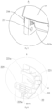
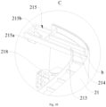
- one side of the first panel 21 facing the back plate component 1 is provided with an engaging hook 218; and as shown in Figs. 11 and 12 , the back plate component 1 is provided with an engaging buckle 15 where the engaging hook 218 extends. It can be seen that the first panel 21 can be connected to the back plate component 1 by the engagement between the engaging hook 218 and the engaging buckle 15. Thereby, the manner in which the first panel 21 and the back plate component 1 are connected is simple and reliable.
- the engaging hook 218 includes a horizontal extending section 218a and a vertical extending section 218b, one end of the horizontal extending section 218a is disposed on the first panel 21, and the other end of the horizontal extending section 218a is connected to the upper end of the vertical extending section 218b, and the lower end of the vertical extending section 218b is adapted to extend into the engaging buckle 15. Therefore, it can be seen that the engaging hook 218 is formed substantially in a "7" shape, making the structure of the engaging hook 218 simpler and convenient to manufacture.
- the lower end of the vertical extending section 218b needs to be engaged with the engaging buckle 15, and then the first panel 21 is pushed downward so that the vertical extending section 218b can fully extend into the engaging buckle 15 and securely engage with the engaging buckle 15, playing a prepositioning role through engagement between the engaging hook 218 and the engaging buckle 15, making the connection between the first panel 21 and the back plate component 1 more reliably, thereby improving the reliability of the indoor unit 100 of air conditioner.
- the engaging buckle 15 is formed as a hollow structure. Consequently, the strength of the engaging hook 218 is improved, the strength of the joint between the first panel 21 and the back plate component 1 is improved, and the material consumption of the first panel 21 is reduced, and the cost is reduced.
- the top of the side of the first panel 21 facing the back plate component 1 is provided with an extension 215 extending toward the back plate component 1, and the lower end of the extension 215 is provided with a positioning post 215a.
- the top of the back plate component 1 is provided with a positioning hole 11, and the positioning post 215a is adapted to extend into the positioning hole 11. It can be seen that the first panel 21 can be connected to the backboard component 1 by the engagement between the positioning post 215a and the positioning hole 11.
- the connection mode is simple and easy to operate, which is advantageous for improving the reliability of the first panel 21 connected to the back plate component 1.
- the extension 215 is provided with a first engaging hole 215b
- the back plate component 1 is provided with a second engaging hole 12
- the second engaging hole 12 is disposed opposite to the first engaging hole 215b.
- the indoor unit 100 of air conditioner further includes a first connector, and the first connector passes through the first engaging hole 215b and the second engaging hole 12 to connect the first panel 21 and the back plate component 1. Consequently, before the first connector passes through the first engaging hole 215b and the second engaging hole 12, the positioning post 215a on the extension 215 can extend into the positioning hole 11 on the back plate component 1, and thereby substantially stabilize the position of the extension 215 relative to the back plate component 1. At this time, the first engaging hole 215b can directly face the second engaging hole 12, thus facilitating the first connector to pass through the first engaging hole 215b and the second engaging hole 12 and improving the assembly efficiency between the first panel 21 and the back plate component 1.
- the bottom of the side of the first panel 21 facing the back plate component 1 is provided with a positioning pin 216 extending toward the back plate component 1.
- the back plate component 1 is provided with a positioning receptacle 13.
- the positioning pin 216 is adapted to be inserted into the positioning receptacle 13. It can be seen that the bottom of the first panel 21 can be connected to the back plate component 1 by the engagement between the engaging hook 216 and the engaging buckle 13, and the connection method is simple and reliable, and easy for mounting and dismounting.
- the positioning pin 216 also has a certain pre-positioning function, which is beneficial to improve the efficiency of assembling and connecting the first panel 21 and the back plate component 1.
- the first panel 21 is provided with a third engaging hole 217
- the third engaging hole 217 is disposed adjacent to the positioning pin 216
- the back plate component 1 is provided with a fourth engaging hole 14
- the fourth engaging hole 14 is disposed opposite to the third engaging hole 217
- the indoor unit 100 of air conditioner further includes a second connector, and the second connector passes through the third engaging hole 217 and the fourth engaging hole 14 so as to connect the first panel 21 and the back plate component 1.
- the positioning pin 216 on the first panel 21 can extend into the positioning hole 13 on the back plate component 1, and thereby substantially stabilize the position of the first panel 21 relative to the back plate component 1.
- the third engaging hole 217 can directly face the fourth engaging hole 14, thus facilitating the second connector to pass through the third engaging hole 217 and the second engaging hole 14 and improving the assembly efficiency between the first panel 21 and the back plate component 1.
- the bottom of the first panel 21 is stably connected to the back plate component 1.
- the panel component 2 further includes an opening and closing element 25, and the opening and closing element 25 moves back and forth to open or close the second air outlet 211b, and when the opening and closing element 25 moves forward to the front of the second air outlet 211b, the opening and closing element 25 opens the second air outlet 211b.
- the opening and closing element 25 moves forward to the front side of the second air outlet 211b
- the second air outlet 211 b is opened to realize the ventilation function.
- the opening and closing element 25 moves rearward to the second air outlet 211b or at the rear of the second air outlet 211b
- the second air outlet 211b is closed. Thereby, the second air outlet 211b can be sealed to prevent particles such as dust in the room from entering the interior of the indoor unit 100 of air conditioner through the second air outlet 211b.
- the top of the first panel 21 is provided with multiple spaced first reinforcing ribs 214. Therefore, the strength of the top of the first panel 21 can be improved.
- the stability of the first panel 21 on the back plate component 1 can be improved, thereby improving the reliability of the air conditioner indoor unit.
- the appearance surface of the first panel 21 is formed as a curved surface. Therefore, the strength of the first panel 21 can be improved, and the reliability and appearance of the indoor unit 100 of air conditioner can be improved.
- an indoor unit 100 of air conditioner based on an embodiment of the present invention is in the form of cabinet.
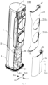
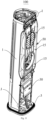
- the indoor unit 100 of air conditioner includes a back plate component 1, a panel component 2, a top cover component 5, a fan 20, an electric control gear 30, and a driving mechanism 40.
- the panel component 2 is located at the front of and engaged with the back plate component 1.
- the panel component 2 includes a first panel 21 and a second panel 22 which are separately formed, and the first panel 21 and the second panel 22 are detachably connected.
- the first panel 21 and the second panel 22 are sequentially arranged in the up and down direction and are respectively connected to the back plate component 1.
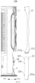
- the bottom of the first panel 21 is folded back and forth to define the connecting plate 212, so that the front surface of the connecting plate 212 and the front surface of the first panel 21 are formed as stepped surfaces.
- the connecting plate 212 is provided with two spaced engaging slots 212b.
- two ends of the connecting plate 212 in the left-right direction are respectively provided with a guiding jack 212a.
- the rear surface of the top of the second panel 22 is provided with a fixing plate 221 extending in the same direction as the extending direction of the second panel 22.
- the left and right ends of the fixing plate 221 are respectively bent forward to define two guiding pins 221a respectively.
- the guiding pins 221a are adapted to insert into the corresponding guiding jacks 212a, thereby fixing the relative positions between the first panel 21 and the second panel 22.
- the rear surface of the fixing plate 221 is provided with two engaging clip bulges 221b, and the two engaging clip bulges 221b are respectively arranged corresponding to the two engaging slots 212b on the connecting plate 212, and each of the engaging clip bulges 221b engages with the buckles of the corresponding engaging groove 212b. Therefore, it can be seen that the second panel 22 connects with the connecting plate 212 on the first panel 21, and the front wall surface of the second panel 22 is level with the front wall surface of the first panel 21 after being assembled and connected. Therefore, the engaging and connecting manner of the first panel 21 and the second panel 22 is simple, easy to operate, and easy to disassemble, and at the same time, the appearance of the first panel 21 and the second panel 22 can be made more beautiful.
- a lower part of the rear surface of the second panel 22 is provided with a first supporting plate 223.
- the first supporting plate 223 extends in the same direction as the second panel 22, and the first support plate 223 is provided with an engaging pin 223a extending downward.
- Fig. 7 a lower part of the rear surface of the second panel 22 is provided with a first supporting plate 223.
- the first supporting plate 223 extends in the same direction as the second panel 22, and the first support plate 223 is provided with an engaging pin 223a extending downward.
- a cavity is disposed between the front surface of the first supporting plate 223 and the rear surface of the second panel 22, and multiple second reinforcing ribs 224 are disposed in the cavity, and both ends of each of the second reinforcing ribs 224 are respectively connected to the first supporting plate 223 and the second panel 22, and the joint between the second reinforcing rib 224 and the second panel 22 is provided with a first thickness reducing zone a.
- the joint between the second reinforcing rib 224 and the second panel 22 can be effectively prevented from being shrunk during the injection molding process, thereby preventing the second panel 22 from being deformed, thus improving the appearance, and improving the overall strength of the second panel 22, and simultaneously improving the yield of the injection molding of the second panel 22.
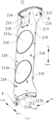
- the top of the rear surface of the first panel 21 is provided with a second supporting plate 213, and the second supporting plate 213 extends in the same direction as the second panel 22 extends.
- a cavity is disposed between the front surface of the second supporting plate 213 and the rear surface of the first panel 21, and multiple first reinforcing ribs 214 are disposed in the cavity, and both ends of each of the first reinforcing ribs 214 are respectively connected to the seconding supporting plate 213 and the first panel 21, and the joint between the first reinforcing rib 214 and the first panel 21 is provided with a second thickness reducing zone b.
- a cavity is disposed between the front surface of the supporting plate 221 and the rear surface of the second panel 22, and multiple third reinforcing ribs 222 are disposed in the cavity, and both ends of each of the third reinforcing ribs 222 are respectively connected to the supporting plate 221 and the second panel 22.
- the joint between each third reinforcing rib 222 and the second panel 22 is provided with a third thickness reducing zone c. Therefore, the material consumption in the injection molding process of the joint between the third reinforcing rib 222 and the second panel 22 can be reduced to some extent.
- the joint between the third reinforcing rib 222 and the second panel 22 can be effectively prevented from being shrunk during the injection molding process, thereby preventing the second panel 22 from being deformed, thus improving the appearance, and improving the overall strength of the second panel 22, and simultaneously improving the yield of the injection molding of the second panel 22.
- the rear surface of the second panel 22 is provided with multiple spaced fourth reinforcing ribs 227, which is beneficial to improve the structural strength and reliability of the second panel 22, thereby improving the reliability of the indoor unit 100 of air conditioner.
- the top of the rear surface of the first panel 21 is provided with an extension 215 extending toward the back plate component 1, and there are two extensions 215 located at both ends of the second supporting plate 213.
- a positioning post 215a is provided at the lower end of each of the extensions 215.
- the top of the back plate 1 is provided with a positioning hole 11 corresponding to each positioning post 215a, and the positioning post 215a is adapted to extend into the corresponding positioning hole 11.
- each of the extensions 215 is provided with a first engaging hole 215b. As shown in Fig.
- the back plate component 1 is provided with a second engaging hole 12, and the second engaging hole 12 faces directly to the first engaging hole 215b, and the screw passes through the first engaging hole 215b and the second engaging hole 12 to connect the first panel 21 and the back plate component 1.
- the top of the rear surface of the first panel 21 is provided with a positioning pin 216 extending toward the back plate component 1.
- the back plate component 1 is provided with a positioning receptacle 13.
- the positioning pin 216 is adapted to be inserted into the positioning receptacle 13.
- the first panel 21 is provided with a third engaging hole 217, the third engaging hole 217 is disposed adjacent to the positioning pin 216, as shown in Fig. 14 , the back plate component 1 is provided with a fourth engaging hole 14, the fourth engaging hole 14 is disposed opposite to the third engaging hole 217, and the screw passes through the third engaging hole 217 and the fourth engaging hole 14 to connect the first panel 21 and the back plate component 1.
- the rear surface of the first panel 21 is provided with an engaging hook 218.
- the back plate component 1 is provided with an engaging buckle 15 where the engaging hook 218 extends.
- the engaging hook 218 includes a horizontal extending section 218a and a vertical extending section 218b, one end of the horizontal extending section 218a is disposed on the first panel 21, and the other end of the horizontal extending section 218a is connected to the upper end of the vertical extending section 218b, and the lower end of the vertical extending section 218b is adapted to extend into the engaging buckle 15.
- the engaging buckle 15 is formed as a hollow structure.
- the indoor unit 100 of air conditioner further includes an air outlet frame component 50, and the air outlet frame component 50 is connected to the back plate component 1, and the air outlet frame component 50 is also provided with an engaging buckle 15.
- the indoor unit 100 of air conditioner further includes a chassis 3, and the back plate component 1 is located above the chassis 3 and connected to the chassis 3.
- the second panel 22 is disposed on the chassis 3, as shown in Fig. 4 and Fig. 7
- the chassis 3 is provided with an engaging jack 31, and the engaging pin 223a on the second panel 22 is adapted to be inserted into the engaging jack 31.
- the back plate component 1, the panel component 2, the chassis 3, the protection cover 4, and the top cover component 5 constitute the housing 10 of the indoor unit 100 of air conditioner.
- the rear surface of the second panel 22 is provided with two spaced engaging posts 225 extending toward the back plate component 1, and each of the engaging posts 225 is provided with a fifth engaging hole 225a.
- the front surface of the back plate component 1 is provided with rearwards recessed engaging slots 16, each engaging post 225 extends into the corresponding engaging groove 16, and each of the fifth engaging holes 225a is in the corresponding engaging groove 16, the side wall of each engaging groove 16 is provided with a sixth engaging hole 16a, and the sixth engaging hole 16a is respectively located on the left side wall and the right side wall of the back plate component 1.
- the outer circumferential wall of the back plate component 1 is provided with inwardly recessed operating groove 17, each of sixth engaging holes 16a is connected to a correspondingly disposed operating groove 17 and engaging groove 16.
- the screw After passing through the operating groove 17, the screw connects to the corresponding fifth engaging hole 225a and the sixth engaging hole 16a, while the screw cap can be clamped on the bottom wall of the operating groove 17.
- the second panel 22 can be reliably connected to the back plate component 1 for easy disassembly.
- the indoor unit 100 of air conditioner further includes a protecting cover 4 that is detachably provided at the operating groove 17 so as to open or plug the opening of the operating groove 17.
- the protecting cover 4 engages with the operating groove 17.
- the edge of the protecting cover 4 is provided with a notch 41. Thereby facilitate the removal of the protecting cover 4 from the operating groove 17.
- the protecting cover 4 closes the operating groove 17, the outer wall surface of the protecting cover 4 is level with the outer wall surface of the back plate component 1. Therefore, the appearance of the indoor unit 100 of air conditioner can be more beautiful.
- the rear surface of the second panel 22 is provided with multiple spaced connecting pins 226.
- the back plate component 1 is provided with multiple connecting jacks 18, and the connecting pins 226 are disposed in one-to-one correspondence with the connection jacks 18, and each of the connecting pins 226 is adapted to extend into the corresponding connecting jack 18.
- the top cover component 5 is connected to the tops of back plate component 1 and the panel component 2, respectively.
- the first air outlet 211a and the second air outlet 211b are disposed on the first panel 21, and the first air outlet 211a and the second air outlet 211b are sequentially arranged in the up and down direction.
- the panel component 2 also includes the opening and closing door mounting plate 23, and the opening and closing door mounting plate 23 is disposed at the rear of the first panel 21.
- the opening and closing door mounting plate 23 is provided with opening and closing door 24, and the opening and closing door 24 is movable relative to the opening and closing door mounting plate 23 so as to open or close the first air outlet 211a.
- the drive mechanism 40 includes an actuator, a drive gear 401, and a rack 402.
- the actuator is disposed on the opening and closing door mounting plate 23, and the drive gear 401 is connected to the actuator to be driven to rotate by the actuator, the rack 402 is connected to the opening and closing door 24, and the rack 402 cooperates with the drive gear 401 to drive the opening and closing door 24 to move.
- the panel component 2 further includes a opening and closing element 25, and the opening and closing element 25 moves back and forth to open or close the second air outlet 211b, and when the opening and closing element 25 moves forward to the front of the second air outlet 211b, the opening and closing element 25 opens the second air outlet 211b.
- the fan 20 is disposed in the housing 10 and located on the rear side of the first panel 21.
- the second fan 202 is disposed opposite to the second air outlet 211b so as to supply air to the second air outlet 211b.
- the first fan 201 includes a first wind wheel and a second wind wheel disposed opposite to each other in a front-rear direction, the blades of the first wind wheel and the second wind wheel slope in opposite directions, the first wind wheel and the second wind wheel are guide vanes for each other in the direction of air flow, thereby reducing (when the first wind wheel and the second wind wheel rotate at different speeds) or eliminating (when the first wind wheel and the second wind wheel rotate at the same speed) the rotational speed of the tangential direction of the airflow (i.e., convert from static pressure to static pressure) and improving the efficiency of the work applied by the counter-rotating fan on the air, and the airflow passing through the two wind wheels is directed toward the first air outlet 211a, thus realizing long-distance air supply.
- the counter-rotating fan can realize air supply over greater distance whether the first wind wheel and the second wind wheel rotate in opposite directions at different speeds or at the same speed.
- the first wind wheel and the second wind wheel can expand the supplying range of the cool air at different rotation speeds. Because when one wind wheel rotates at a higher speed and the other wind wheel rotates at a lower speed, the wind wheel rotating at higher speed plays a leading role, and the blade airflow outlet angle based on the single-stage axial flow or diagonal flow fan is designed off the direction of the rotation axis, making the axial flow or the diagonal flow wheel itself has a wind-dissipating effect, and therefore, the angle of the cool air flowing out from the first air outlet 211a is large, realizing wide-angle air supply.
- the indoor unit 100 of air conditioner based on the embodiment of the present disclosure can realize a gentle feeling or a breezeless feeling air supply without using a wind deflector with micro holes, and the air loss is small.
- the "forward air supply” means that the air flow is blown from the first air outlet 211a by the action of the wind wheel
- the "reverse air supply” means that the air flow is blown into the inside of the housing 10.
- the electronic control gear 30 is disposed in the housing 10.
- the electronic control gear 30 is connected to the first fan 201 and the second fan 202 and is used to control the operating state of the indoor unit 100 of air conditioner.
- the electric control gear 30 is provided at the rear of the second panel 22. Therefore, while repairing the electronic control gear 30, it is only necessary to dismount the second panel 22 without dismounting the first panel 21.
- an embodiment means that the specific feature, structure, material or characteristic of that embodiment or example described are included in at least one embodiment or example of the present invention.
- the schematic presentation of such terms may not refer to the same embodiment or example.
- the specific features, structure, material or characteristics described may be combined in an appropriate manner in any one or multiple embodiments or examples.
Landscapes
- Engineering & Computer Science (AREA)
- Chemical & Material Sciences (AREA)
- Combustion & Propulsion (AREA)
- Mechanical Engineering (AREA)
- General Engineering & Computer Science (AREA)
- Air Filters, Heat-Exchange Apparatuses, And Housings Of Air-Conditioning Units (AREA)
- Air-Flow Control Members (AREA)
- Air-Conditioning Room Units, And Self-Contained Units In General (AREA)
Claims (15)
- Klimaanlagen-Inneneinheit (100), umfassend:eine Rückplattenkomponente (1);eine obere Abdeckungskomponente (5), wobei ein Teil der oberen Abdeckungskomponente mit einer oberen Wand der Rückplattenkomponente verbunden ist;eine Blendenkomponente (2), wobei die Blendenkomponente Folgendes umfasst:
eine erste Blende (21), wobei ein oberes Ende der ersten Blende mit einem anderen Teil der oberen Abdeckungskomponente verbunden ist, wobei die erste Blende vor der Rückplattenkomponente angeordnet und mit der Rückplattenkomponente verbunden ist, wobei die erste Blende mit einem ersten Luftauslass und einem zweiten Luftauslass, die in einer Aufwärts-Abwärts-Richtung hintereinander angeordnet sind, versehen ist,dadurch gekennzeichnet, dass die Blende ferner Folgendes umfasst:eine zweite Blende (22), die unter der ersten Blende angeordnet und mit einem jeweiligen unteren Ende der ersten Blende und der Rückplattenkomponente verbunden ist, und wobei die zweite Blende und die erste Blende unabhängig verarbeitet und geformt sind;eine Anbauplatte (23) für eine öffnende und schließende Klappe, die hinter der ersten Blende angeordnet und mit einer sich in der Aufwärts-Abwärts-Richtung erstreckenden Führungsnut (231) versehen ist;eine öffnende und schließende Klappe (24), die zwischen der ersten Blende und der Anbauplatte für die öffnende und schließende Klappe angeordnet ist, wobei die öffnende und schließende Klappe relativ zu der Anbauplatte für die öffnende und schließende Klappe nach oben und nach unten bewegbar ist, um den ersten Luftauslass (211a) zu öffnen oder zu schließen, wobei ein Führungszapfen (241) an der öffnenden und schließenden Klappe angeordnet und dazu konfiguriert ist, sich in die Führungsnut zu erstrecken, und der Führungszapfen relativ zu der Führungsnut gleitfähig ist. - Klimaanlagen-Inneneinheit nach Anspruch 1, wobei sich ein geneigter Abschnitt (231b) der Führungsnut (231) schräg nach unten in Richtung des ersten Luftauslasses (211a) erstreckt und die öffnende und schließende Klappe den ersten Luftauslass schließt, wenn der Führungszapfen in den geneigten Abschnitt der Führungsnut gleitet.
- Klimaanlagen-Inneneinheit nach Anspruch 2, ferner umfassend einen Begrenzungsverbinder (6), wobei ein Ende des Begrenzungsverbinders gleitfähig an der Anbauplatte für die öffnende und schließende Klappe angeordnet ist und das andere Ende des Begrenzungsverbinders drehbar an der öffnenden und schließenden Klappe angeordnet ist, sodass der Begrenzungsverbinder dazu konfiguriert ist, die öffnende und schließende Klappe dazu anzutreiben, sich zu bewegen.
- Klimaanlagen-Inneneinheit nach Anspruch 3, ferner umfassend einen Antriebsmechanismus (40), wobei der Antriebsmechanismus mit dem Begrenzungsverbinder verbunden ist, um den Begrenzungsverbinder dazu anzutreiben, zu gleiten, um die öffnende und schließende Klappe dazu anzutreiben, sich zu bewegen.
- Klimaanlagen-Inneneinheit nach Anspruch 4, wobei der Antriebsmechanismus Folgendes umfasst:einen Aktor, der an der Anbauplatte für die öffnende und schließende Klappe angeordnet ist;ein Antriebszahnrad (401), das mit dem Aktor verbunden ist und von dem Aktor dazu angetrieben wird, sich zu drehen;eine Zahnstange (402), die mit dem Begrenzungsverbinder verbunden ist und sich mit dem Antriebszahnrad im Eingriff befindet, um den Begrenzungsverbinder dazu anzutreiben, zu gleiten.
- Klimaanlagen-Inneneinheit nach einem der Ansprüche 1-5, wobei eine der Rückplattenkomponente zugewandte Seite der ersten Blende mit einem Eingriffshaken versehen ist, die Rückplattenkomponente mit einem Eingriffsbügel versehen ist und der Eingriffshaken dazu konfiguriert ist, sich in den Eingriffsbügel zu erstrecken.
- Klimaanlagen-Inneneinheit nach Anspruch 6, wobei der Eingriffshaken einen sich horizontal erstreckenden Abschnitt und einen sich vertikal erstreckenden Abschnitt umfasst, wobei ein Ende des sich horizontal erstreckenden Abschnitts an der ersten Blende angeordnet ist, das andere Ende des sich horizontal erstreckenden Abschnitts mit einem oberen Ende des sich vertikal erstreckenden Abschnitts verbunden ist und ein unteres Ende des sich vertikal erstreckenden Abschnitts dazu konfiguriert ist, sich in den Eingriffsbügel zu erstrecken.
- Klimaanlagen-Inneneinheit nach Anspruch 6, wobei der Eingriffsbügel als hohle Struktur konfiguriert ist.
- Klimaanlagen-Inneneinheit nach einem der Ansprüche 1-8, wobei eine der Rückplattenkomponente zugewandte Seite der ersten Blende oben mit einer Verlängerung versehen ist, die sich in Richtung der Rückplattenkomponente erstreckt, ein unteres Ende der Verlängerung mit einem Positionierungszapfen versehen ist, die Rückplattenkomponente oben mit einem Positionierungsloch versehen ist und der Positionierungszapfen dazu konfiguriert ist, sich in das Positionierungsloch zu erstrecken.
- Klimaanlagen-Inneneinheit nach Anspruch 9, wobei die Verlängerung mit einem ersten Eingriffsloch versehen ist, die Rückplattenkomponente mit einem zweiten Eingriffsloch versehen ist und das zweite Eingriffsloch dem ersten Eingriffsloch gegenüber angeordnet ist,
wobei die Klimaanlagen-Inneneinheit ferner einen ersten Verbinder umfasst und der erste Verbinder durch das erste Eingriffsloch und das zweite Eingriffsloch läuft, um die erste Blende mit der Rückplattenkomponente zu verbinden. - Klimaanlagen-Inneneinheit nach einem der Ansprüche 1-10, wobei eine der Rückplattenkomponente zugewandte Seite der ersten Blende unten mit einem Positionierungsstift versehen ist, der sich in Richtung der Rückplattenkomponente erstreckt, die Rückplattenkomponente mit einer Positionierungsaufnahme versehen ist und der Positionierungsstift dazu konfiguriert ist, in die Positionierungsaufnahme eingesteckt zu werden.
- Klimaanlagen-Inneneinheit nach Anspruch 11, wobei die erste Blende mit einem dritten Eingriffsloch versehen ist, das dritte Eingriffsloch dem Positionierungsstift benachbart angeordnet ist, die Rückplattenkomponente mit einem vierten Eingriffsloch versehen ist und das vierte Eingriffsloch dem dritten Eingriffsloch gegenüber angeordnet ist,
wobei die Klimaanlagen-Inneneinheit ferner einen zweiten Verbinder umfasst und der zweite Verbinder durch das dritte Eingriffsloch und das vierte Eingriffsloch läuft, um die erste Blende mit der Rückplattenkomponente zu verbinden. - Klimaanlagen-Inneneinheit nach einem der Ansprüche 1-12, wobei die Blendenkomponente ferner ein öffnendes und schließendes Element (25) umfasst und das öffnende und schließende Elemente (25) dazu konfiguriert ist, sich vor und zurück zu bewegen, um den zweiten Luftauslass zu öffnen oder zu schließen, und, wenn sich das öffnende und schließende Element nach vorne bewegt, um sich vor dem zweiten Luftauslass zu befinden, die öffnende und schließende Klappe den zweiten Luftauslass öffnet.
- Klimaanlagen-Inneneinheit nach einem der Ansprüche 1-13, wobei die erste Blende oben mit einer Vielzahl von ersten Verstärkungsrippen versehen ist, die voneinander beabstandet sind.
- Klimaanlagen-Inneneinheit nach einem der Ansprüche 1-14, wobei eine Sichtoberfläche der ersten Blende als gekrümmte Oberfläche konfiguriert ist.
Applications Claiming Priority (3)
| Application Number | Priority Date | Filing Date | Title |
|---|---|---|---|
| CN201910143726.3A CN109945309A (zh) | 2019-02-25 | 2019-02-25 | 空调室内机 |
| CN201920239558.3U CN209558536U (zh) | 2019-02-25 | 2019-02-25 | 空调室内机 |
| PCT/CN2019/080065 WO2020172938A1 (zh) | 2019-02-25 | 2019-03-28 | 空调室内机 |
Publications (3)
| Publication Number | Publication Date |
|---|---|
| EP3722684A4 EP3722684A4 (de) | 2020-10-14 |
| EP3722684A1 EP3722684A1 (de) | 2020-10-14 |
| EP3722684B1 true EP3722684B1 (de) | 2023-04-26 |
Family
ID=69699725
Family Applications (1)
| Application Number | Title | Priority Date | Filing Date |
|---|---|---|---|
| EP19778419.2A Active EP3722684B1 (de) | 2019-02-25 | 2019-03-28 | Klimaanlageninnenraumeinheit |
Country Status (5)
| Country | Link |
|---|---|
| US (1) | US11566795B2 (de) |
| EP (1) | EP3722684B1 (de) |
| JP (1) | JP7071399B2 (de) |
| KR (1) | KR102343746B1 (de) |
| WO (1) | WO2020172938A1 (de) |
Families Citing this family (1)
| Publication number | Priority date | Publication date | Assignee | Title |
|---|---|---|---|---|
| CN119063076B (zh) * | 2024-09-25 | 2025-10-24 | 珠海格力电器股份有限公司 | 一种立式空调室内机、立式空调器和装配方法 |
Family Cites Families (17)
| Publication number | Priority date | Publication date | Assignee | Title |
|---|---|---|---|---|
| JP3680148B2 (ja) * | 2001-07-24 | 2005-08-10 | ダイキン工業株式会社 | 空気調和装置の室外機 |
| KR20100012306A (ko) | 2008-07-28 | 2010-02-08 | 엘지전자 주식회사 | 공기조화기의 실내기 |
| KR101633782B1 (ko) | 2015-01-13 | 2016-06-27 | 엘지전자 주식회사 | 공기조화기 |
| KR101900484B1 (ko) * | 2015-01-23 | 2018-09-20 | 삼성전자주식회사 | 공기 조화기 |
| KR102541386B1 (ko) * | 2015-07-17 | 2023-06-09 | 삼성전자주식회사 | 공기조화기 |
| US11118792B2 (en) * | 2015-07-17 | 2021-09-14 | Samsung Electronics Co., Ltd. | Air conditioner |
| US11193677B2 (en) | 2015-07-21 | 2021-12-07 | Samsung Electronics Co., Ltd. | Air conditioner and control method thereof |
| CN205351517U (zh) | 2016-01-06 | 2016-06-29 | 广东美的制冷设备有限公司 | 立式空调 |
| JP2016195888A (ja) * | 2016-08-26 | 2016-11-24 | 英三 大森 | 組立式棚 |
| CN106287969B (zh) * | 2016-08-31 | 2019-08-30 | 芜湖美智空调设备有限公司 | 一种空调室内机及其控制方法 |
| CN206669886U (zh) * | 2017-03-16 | 2017-11-24 | 青岛海尔空调器有限总公司 | 立式空调室内机 |
| CN106958866B (zh) * | 2017-04-17 | 2019-11-05 | 青岛海尔空调器有限总公司 | 空调器室内机 |
| CN207113012U (zh) * | 2017-06-13 | 2018-03-16 | 珠海格力电器股份有限公司 | 空调面板和空调柜机 |
| CN107218660B (zh) | 2017-06-26 | 2019-10-01 | 青岛海尔空调器有限总公司 | 立式空调室内机 |
| CN107965844B (zh) * | 2017-11-21 | 2023-11-07 | 珠海格力电器股份有限公司 | 空调室内机及其控制方法、空调器 |
| KR101962806B1 (ko) | 2018-05-18 | 2019-03-28 | 삼성전자주식회사 | 공기조화기 |
| CN108895543A (zh) * | 2018-05-25 | 2018-11-27 | 珠海格力电器股份有限公司 | 电器装置、空调室内机及其控制方法 |
-
2019
- 2019-03-28 EP EP19778419.2A patent/EP3722684B1/de active Active
- 2019-03-28 WO PCT/CN2019/080065 patent/WO2020172938A1/zh not_active Ceased
- 2019-03-28 KR KR1020197030462A patent/KR102343746B1/ko active Active
- 2019-03-28 JP JP2019556246A patent/JP7071399B2/ja active Active
- 2019-03-28 US US16/499,627 patent/US11566795B2/en active Active
Also Published As
| Publication number | Publication date |
|---|---|
| KR102343746B1 (ko) | 2021-12-27 |
| JP2021519903A (ja) | 2021-08-12 |
| EP3722684A4 (de) | 2020-10-14 |
| KR20200106003A (ko) | 2020-09-10 |
| EP3722684A1 (de) | 2020-10-14 |
| JP7071399B2 (ja) | 2022-05-18 |
| US11566795B2 (en) | 2023-01-31 |
| US20210332985A1 (en) | 2021-10-28 |
| WO2020172938A1 (zh) | 2020-09-03 |
Similar Documents
| Publication | Publication Date | Title |
|---|---|---|
| CN206669886U (zh) | 立式空调室内机 | |
| EP3722684A1 (de) | Klimaanlageninnenraumeinheit | |
| KR20170072374A (ko) | 에어컨 | |
| CN109737503B (zh) | 空调室内机的面板部件及空调室内机 | |
| CN209689032U (zh) | 空调室内机的面板部件及空调室内机 | |
| CN209558536U (zh) | 空调室内机 | |
| CN209558533U (zh) | 空调室内机 | |
| WO2020172939A1 (zh) | 空调室内机的面板部件及空调室内机 | |
| KR20170076837A (ko) | 에어컨 | |
| KR20170076010A (ko) | 에어컨 | |
| CN109945309A (zh) | 空调室内机 | |
| KR20170076003A (ko) | 에어컨 | |
| CN209558642U (zh) | 空调室内机 | |
| CN209325931U (zh) | 空调室内机 | |
| KR20170076839A (ko) | 에어컨 | |
| KR20170076022A (ko) | 에어컨 | |
| CN218955154U (zh) | 空调机壳、立式空调柜机及空调器 | |
| KR20170076016A (ko) | 에어컨 | |
| KR20170076005A (ko) | 에어컨 | |
| KR20170076014A (ko) | 에어컨 | |
| KR20170076021A (ko) | 에어컨 | |
| KR20170076019A (ko) | 에어컨 | |
| KR20170076020A (ko) | 에어컨 | |
| KR20170076834A (ko) | 에어컨 | |
| KR20170076012A (ko) | 에어컨 |
Legal Events
| Date | Code | Title | Description |
|---|---|---|---|
| STAA | Information on the status of an ep patent application or granted ep patent |
Free format text: STATUS: UNKNOWN |
|
| STAA | Information on the status of an ep patent application or granted ep patent |
Free format text: STATUS: THE INTERNATIONAL PUBLICATION HAS BEEN MADE |
|
| PUAI | Public reference made under article 153(3) epc to a published international application that has entered the european phase |
Free format text: ORIGINAL CODE: 0009012 |
|
| STAA | Information on the status of an ep patent application or granted ep patent |
Free format text: STATUS: REQUEST FOR EXAMINATION WAS MADE |
|
| 17P | Request for examination filed |
Effective date: 20191007 |
|
| A4 | Supplementary search report drawn up and despatched |
Effective date: 20200728 |
|
| AK | Designated contracting states |
Kind code of ref document: A1 Designated state(s): AL AT BE BG CH CY CZ DE DK EE ES FI FR GB GR HR HU IE IS IT LI LT LU LV MC MK MT NL NO PL PT RO RS SE SI SK SM TR |
|
| AX | Request for extension of the european patent |
Extension state: BA ME |
|
| RAP3 | Party data changed (applicant data changed or rights of an application transferred) |
Owner name: MIDEA GROUP CO., LTD. Owner name: GD MIDEA AIR-CONDITIONING EQUIPMENT CO., LTD. |
|
| DAV | Request for validation of the european patent (deleted) | ||
| DAX | Request for extension of the european patent (deleted) | ||
| GRAP | Despatch of communication of intention to grant a patent |
Free format text: ORIGINAL CODE: EPIDOSNIGR1 |
|
| STAA | Information on the status of an ep patent application or granted ep patent |
Free format text: STATUS: GRANT OF PATENT IS INTENDED |
|
| INTG | Intention to grant announced |
Effective date: 20230113 |
|
| GRAS | Grant fee paid |
Free format text: ORIGINAL CODE: EPIDOSNIGR3 |
|
| GRAA | (expected) grant |
Free format text: ORIGINAL CODE: 0009210 |
|
| STAA | Information on the status of an ep patent application or granted ep patent |
Free format text: STATUS: THE PATENT HAS BEEN GRANTED |
|
| AK | Designated contracting states |
Kind code of ref document: B1 Designated state(s): AL AT BE BG CH CY CZ DE DK EE ES FI FR GB GR HR HU IE IS IT LI LT LU LV MC MK MT NL NO PL PT RO RS SE SI SK SM TR |
|
| REG | Reference to a national code |
Ref country code: GB Ref legal event code: FG4D |
|
| REG | Reference to a national code |
Ref country code: CH Ref legal event code: EP |
|
| REG | Reference to a national code |
Ref country code: DE Ref legal event code: R096 Ref document number: 602019028104 Country of ref document: DE |
|
| REG | Reference to a national code |
Ref country code: AT Ref legal event code: REF Ref document number: 1563082 Country of ref document: AT Kind code of ref document: T Effective date: 20230515 |
|
| REG | Reference to a national code |
Ref country code: IE Ref legal event code: FG4D |
|
| REG | Reference to a national code |
Ref country code: LT Ref legal event code: MG9D |
|
| REG | Reference to a national code |
Ref country code: NL Ref legal event code: MP Effective date: 20230426 |
|
| REG | Reference to a national code |
Ref country code: AT Ref legal event code: MK05 Ref document number: 1563082 Country of ref document: AT Kind code of ref document: T Effective date: 20230426 |
|
| PG25 | Lapsed in a contracting state [announced via postgrant information from national office to epo] |
Ref country code: NL Free format text: LAPSE BECAUSE OF FAILURE TO SUBMIT A TRANSLATION OF THE DESCRIPTION OR TO PAY THE FEE WITHIN THE PRESCRIBED TIME-LIMIT Effective date: 20230426 |
|
| PG25 | Lapsed in a contracting state [announced via postgrant information from national office to epo] |
Ref country code: SE Free format text: LAPSE BECAUSE OF FAILURE TO SUBMIT A TRANSLATION OF THE DESCRIPTION OR TO PAY THE FEE WITHIN THE PRESCRIBED TIME-LIMIT Effective date: 20230426 Ref country code: PT Free format text: LAPSE BECAUSE OF FAILURE TO SUBMIT A TRANSLATION OF THE DESCRIPTION OR TO PAY THE FEE WITHIN THE PRESCRIBED TIME-LIMIT Effective date: 20230828 Ref country code: NO Free format text: LAPSE BECAUSE OF FAILURE TO SUBMIT A TRANSLATION OF THE DESCRIPTION OR TO PAY THE FEE WITHIN THE PRESCRIBED TIME-LIMIT Effective date: 20230726 Ref country code: ES Free format text: LAPSE BECAUSE OF FAILURE TO SUBMIT A TRANSLATION OF THE DESCRIPTION OR TO PAY THE FEE WITHIN THE PRESCRIBED TIME-LIMIT Effective date: 20230426 Ref country code: AT Free format text: LAPSE BECAUSE OF FAILURE TO SUBMIT A TRANSLATION OF THE DESCRIPTION OR TO PAY THE FEE WITHIN THE PRESCRIBED TIME-LIMIT Effective date: 20230426 |
|
| PG25 | Lapsed in a contracting state [announced via postgrant information from national office to epo] |
Ref country code: RS Free format text: LAPSE BECAUSE OF FAILURE TO SUBMIT A TRANSLATION OF THE DESCRIPTION OR TO PAY THE FEE WITHIN THE PRESCRIBED TIME-LIMIT Effective date: 20230426 Ref country code: PL Free format text: LAPSE BECAUSE OF FAILURE TO SUBMIT A TRANSLATION OF THE DESCRIPTION OR TO PAY THE FEE WITHIN THE PRESCRIBED TIME-LIMIT Effective date: 20230426 Ref country code: LV Free format text: LAPSE BECAUSE OF FAILURE TO SUBMIT A TRANSLATION OF THE DESCRIPTION OR TO PAY THE FEE WITHIN THE PRESCRIBED TIME-LIMIT Effective date: 20230426 Ref country code: LT Free format text: LAPSE BECAUSE OF FAILURE TO SUBMIT A TRANSLATION OF THE DESCRIPTION OR TO PAY THE FEE WITHIN THE PRESCRIBED TIME-LIMIT Effective date: 20230426 Ref country code: IS Free format text: LAPSE BECAUSE OF FAILURE TO SUBMIT A TRANSLATION OF THE DESCRIPTION OR TO PAY THE FEE WITHIN THE PRESCRIBED TIME-LIMIT Effective date: 20230826 Ref country code: HR Free format text: LAPSE BECAUSE OF FAILURE TO SUBMIT A TRANSLATION OF THE DESCRIPTION OR TO PAY THE FEE WITHIN THE PRESCRIBED TIME-LIMIT Effective date: 20230426 Ref country code: GR Free format text: LAPSE BECAUSE OF FAILURE TO SUBMIT A TRANSLATION OF THE DESCRIPTION OR TO PAY THE FEE WITHIN THE PRESCRIBED TIME-LIMIT Effective date: 20230727 |
|
| PG25 | Lapsed in a contracting state [announced via postgrant information from national office to epo] |
Ref country code: FI Free format text: LAPSE BECAUSE OF FAILURE TO SUBMIT A TRANSLATION OF THE DESCRIPTION OR TO PAY THE FEE WITHIN THE PRESCRIBED TIME-LIMIT Effective date: 20230426 |
|
| PG25 | Lapsed in a contracting state [announced via postgrant information from national office to epo] |
Ref country code: SK Free format text: LAPSE BECAUSE OF FAILURE TO SUBMIT A TRANSLATION OF THE DESCRIPTION OR TO PAY THE FEE WITHIN THE PRESCRIBED TIME-LIMIT Effective date: 20230426 |
|
| REG | Reference to a national code |
Ref country code: DE Ref legal event code: R097 Ref document number: 602019028104 Country of ref document: DE |
|
| PG25 | Lapsed in a contracting state [announced via postgrant information from national office to epo] |
Ref country code: SM Free format text: LAPSE BECAUSE OF FAILURE TO SUBMIT A TRANSLATION OF THE DESCRIPTION OR TO PAY THE FEE WITHIN THE PRESCRIBED TIME-LIMIT Effective date: 20230426 Ref country code: SK Free format text: LAPSE BECAUSE OF FAILURE TO SUBMIT A TRANSLATION OF THE DESCRIPTION OR TO PAY THE FEE WITHIN THE PRESCRIBED TIME-LIMIT Effective date: 20230426 Ref country code: RO Free format text: LAPSE BECAUSE OF FAILURE TO SUBMIT A TRANSLATION OF THE DESCRIPTION OR TO PAY THE FEE WITHIN THE PRESCRIBED TIME-LIMIT Effective date: 20230426 Ref country code: EE Free format text: LAPSE BECAUSE OF FAILURE TO SUBMIT A TRANSLATION OF THE DESCRIPTION OR TO PAY THE FEE WITHIN THE PRESCRIBED TIME-LIMIT Effective date: 20230426 Ref country code: DK Free format text: LAPSE BECAUSE OF FAILURE TO SUBMIT A TRANSLATION OF THE DESCRIPTION OR TO PAY THE FEE WITHIN THE PRESCRIBED TIME-LIMIT Effective date: 20230426 Ref country code: CZ Free format text: LAPSE BECAUSE OF FAILURE TO SUBMIT A TRANSLATION OF THE DESCRIPTION OR TO PAY THE FEE WITHIN THE PRESCRIBED TIME-LIMIT Effective date: 20230426 |
|
| PLBE | No opposition filed within time limit |
Free format text: ORIGINAL CODE: 0009261 |
|
| STAA | Information on the status of an ep patent application or granted ep patent |
Free format text: STATUS: NO OPPOSITION FILED WITHIN TIME LIMIT |
|
| 26N | No opposition filed |
Effective date: 20240129 |
|
| PG25 | Lapsed in a contracting state [announced via postgrant information from national office to epo] |
Ref country code: SI Free format text: LAPSE BECAUSE OF FAILURE TO SUBMIT A TRANSLATION OF THE DESCRIPTION OR TO PAY THE FEE WITHIN THE PRESCRIBED TIME-LIMIT Effective date: 20230426 |
|
| PG25 | Lapsed in a contracting state [announced via postgrant information from national office to epo] |
Ref country code: SI Free format text: LAPSE BECAUSE OF FAILURE TO SUBMIT A TRANSLATION OF THE DESCRIPTION OR TO PAY THE FEE WITHIN THE PRESCRIBED TIME-LIMIT Effective date: 20230426 Ref country code: IT Free format text: LAPSE BECAUSE OF FAILURE TO SUBMIT A TRANSLATION OF THE DESCRIPTION OR TO PAY THE FEE WITHIN THE PRESCRIBED TIME-LIMIT Effective date: 20230426 |
|
| REG | Reference to a national code |
Ref country code: CH Ref legal event code: PL |
|
| PG25 | Lapsed in a contracting state [announced via postgrant information from national office to epo] |
Ref country code: BG Free format text: LAPSE BECAUSE OF FAILURE TO SUBMIT A TRANSLATION OF THE DESCRIPTION OR TO PAY THE FEE WITHIN THE PRESCRIBED TIME-LIMIT Effective date: 20230426 |
|
| PG25 | Lapsed in a contracting state [announced via postgrant information from national office to epo] |
Ref country code: LU Free format text: LAPSE BECAUSE OF NON-PAYMENT OF DUE FEES Effective date: 20240328 |
|
| PG25 | Lapsed in a contracting state [announced via postgrant information from national office to epo] |
Ref country code: MC Free format text: LAPSE BECAUSE OF FAILURE TO SUBMIT A TRANSLATION OF THE DESCRIPTION OR TO PAY THE FEE WITHIN THE PRESCRIBED TIME-LIMIT Effective date: 20230426 |
|
| GBPC | Gb: european patent ceased through non-payment of renewal fee |
Effective date: 20240328 |
|
| PG25 | Lapsed in a contracting state [announced via postgrant information from national office to epo] |
Ref country code: MC Free format text: LAPSE BECAUSE OF FAILURE TO SUBMIT A TRANSLATION OF THE DESCRIPTION OR TO PAY THE FEE WITHIN THE PRESCRIBED TIME-LIMIT Effective date: 20230426 Ref country code: LU Free format text: LAPSE BECAUSE OF NON-PAYMENT OF DUE FEES Effective date: 20240328 Ref country code: BG Free format text: LAPSE BECAUSE OF FAILURE TO SUBMIT A TRANSLATION OF THE DESCRIPTION OR TO PAY THE FEE WITHIN THE PRESCRIBED TIME-LIMIT Effective date: 20230426 |
|
| REG | Reference to a national code |
Ref country code: BE Ref legal event code: MM Effective date: 20240331 |
|
| PG25 | Lapsed in a contracting state [announced via postgrant information from national office to epo] |
Ref country code: BE Free format text: LAPSE BECAUSE OF NON-PAYMENT OF DUE FEES Effective date: 20240331 |
|
| PG25 | Lapsed in a contracting state [announced via postgrant information from national office to epo] |
Ref country code: GB Free format text: LAPSE BECAUSE OF NON-PAYMENT OF DUE FEES Effective date: 20240328 |
|
| PG25 | Lapsed in a contracting state [announced via postgrant information from national office to epo] |
Ref country code: IE Free format text: LAPSE BECAUSE OF NON-PAYMENT OF DUE FEES Effective date: 20240328 |
|
| PG25 | Lapsed in a contracting state [announced via postgrant information from national office to epo] |
Ref country code: IE Free format text: LAPSE BECAUSE OF NON-PAYMENT OF DUE FEES Effective date: 20240328 Ref country code: GB Free format text: LAPSE BECAUSE OF NON-PAYMENT OF DUE FEES Effective date: 20240328 Ref country code: BE Free format text: LAPSE BECAUSE OF NON-PAYMENT OF DUE FEES Effective date: 20240331 Ref country code: CH Free format text: LAPSE BECAUSE OF NON-PAYMENT OF DUE FEES Effective date: 20240331 |
|
| PG25 | Lapsed in a contracting state [announced via postgrant information from national office to epo] |
Ref country code: CY Free format text: LAPSE BECAUSE OF FAILURE TO SUBMIT A TRANSLATION OF THE DESCRIPTION OR TO PAY THE FEE WITHIN THE PRESCRIBED TIME-LIMIT; INVALID AB INITIO Effective date: 20190328 |
|
| PG25 | Lapsed in a contracting state [announced via postgrant information from national office to epo] |
Ref country code: HU Free format text: LAPSE BECAUSE OF FAILURE TO SUBMIT A TRANSLATION OF THE DESCRIPTION OR TO PAY THE FEE WITHIN THE PRESCRIBED TIME-LIMIT; INVALID AB INITIO Effective date: 20190328 |
|
| PG25 | Lapsed in a contracting state [announced via postgrant information from national office to epo] |
Ref country code: TR Free format text: LAPSE BECAUSE OF FAILURE TO SUBMIT A TRANSLATION OF THE DESCRIPTION OR TO PAY THE FEE WITHIN THE PRESCRIBED TIME-LIMIT Effective date: 20230426 |
|
| PGFP | Annual fee paid to national office [announced via postgrant information from national office to epo] |
Ref country code: DE Payment date: 20260324 Year of fee payment: 8 |
|
| PGFP | Annual fee paid to national office [announced via postgrant information from national office to epo] |
Ref country code: FR Payment date: 20260330 Year of fee payment: 8 |