EP3722682B1 - Indoor unit of air conditioning apparatus, and air conditioning apparatus - Google Patents
Indoor unit of air conditioning apparatus, and air conditioning apparatus Download PDFInfo
- Publication number
- EP3722682B1 EP3722682B1 EP17933984.1A EP17933984A EP3722682B1 EP 3722682 B1 EP3722682 B1 EP 3722682B1 EP 17933984 A EP17933984 A EP 17933984A EP 3722682 B1 EP3722682 B1 EP 3722682B1
- Authority
- EP
- European Patent Office
- Prior art keywords
- hose
- pipe
- air
- heat
- indoor unit
- Prior art date
- Legal status (The legal status is an assumption and is not a legal conclusion. Google has not performed a legal analysis and makes no representation as to the accuracy of the status listed.)
- Active
Links
- 238000004378 air conditioning Methods 0.000 title claims description 61
- XLYOFNOQVPJJNP-UHFFFAOYSA-N water Substances O XLYOFNOQVPJJNP-UHFFFAOYSA-N 0.000 claims description 93
- 230000005494 condensation Effects 0.000 claims description 6
- 238000009833 condensation Methods 0.000 claims description 6
- 239000000463 material Substances 0.000 claims description 5
- 239000003507 refrigerant Substances 0.000 description 20
- 238000001816 cooling Methods 0.000 description 10
- 238000010438 heat treatment Methods 0.000 description 10
- 239000000853 adhesive Substances 0.000 description 2
- 230000001070 adhesive effect Effects 0.000 description 2
- 239000012267 brine Substances 0.000 description 2
- 230000000694 effects Effects 0.000 description 2
- HPALAKNZSZLMCH-UHFFFAOYSA-M sodium;chloride;hydrate Chemical compound O.[Na+].[Cl-] HPALAKNZSZLMCH-UHFFFAOYSA-M 0.000 description 2
- 239000007779 soft material Substances 0.000 description 2
- 101150006573 PAN1 gene Proteins 0.000 description 1
- 230000003247 decreasing effect Effects 0.000 description 1
- 230000001419 dependent effect Effects 0.000 description 1
- ZZUFCTLCJUWOSV-UHFFFAOYSA-N furosemide Chemical group C1=C(Cl)C(S(=O)(=O)N)=CC(C(O)=O)=C1NCC1=CC=CO1 ZZUFCTLCJUWOSV-UHFFFAOYSA-N 0.000 description 1
- 230000012447 hatching Effects 0.000 description 1
- 238000000034 method Methods 0.000 description 1
- 230000002093 peripheral effect Effects 0.000 description 1
- 239000000243 solution Substances 0.000 description 1
Images


Classifications
-
- F—MECHANICAL ENGINEERING; LIGHTING; HEATING; WEAPONS; BLASTING
- F24—HEATING; RANGES; VENTILATING
- F24F—AIR-CONDITIONING; AIR-HUMIDIFICATION; VENTILATION; USE OF AIR CURRENTS FOR SCREENING
- F24F1/00—Room units for air-conditioning, e.g. separate or self-contained units or units receiving primary air from a central station
- F24F1/0007—Indoor units, e.g. fan coil units
- F24F1/0059—Indoor units, e.g. fan coil units characterised by heat exchangers
- F24F1/0063—Indoor units, e.g. fan coil units characterised by heat exchangers by the mounting or arrangement of the heat exchangers
-
- F—MECHANICAL ENGINEERING; LIGHTING; HEATING; WEAPONS; BLASTING
- F24—HEATING; RANGES; VENTILATING
- F24F—AIR-CONDITIONING; AIR-HUMIDIFICATION; VENTILATION; USE OF AIR CURRENTS FOR SCREENING
- F24F13/00—Details common to, or for air-conditioning, air-humidification, ventilation or use of air currents for screening
- F24F13/22—Means for preventing condensation or evacuating condensate
- F24F13/222—Means for preventing condensation or evacuating condensate for evacuating condensate
-
- F—MECHANICAL ENGINEERING; LIGHTING; HEATING; WEAPONS; BLASTING
- F16—ENGINEERING ELEMENTS AND UNITS; GENERAL MEASURES FOR PRODUCING AND MAINTAINING EFFECTIVE FUNCTIONING OF MACHINES OR INSTALLATIONS; THERMAL INSULATION IN GENERAL
- F16L—PIPES; JOINTS OR FITTINGS FOR PIPES; SUPPORTS FOR PIPES, CABLES OR PROTECTIVE TUBING; MEANS FOR THERMAL INSULATION IN GENERAL
- F16L11/00—Hoses, i.e. flexible pipes
- F16L11/20—Double-walled hoses, i.e. two concentric hoses
-
- F—MECHANICAL ENGINEERING; LIGHTING; HEATING; WEAPONS; BLASTING
- F24—HEATING; RANGES; VENTILATING
- F24F—AIR-CONDITIONING; AIR-HUMIDIFICATION; VENTILATION; USE OF AIR CURRENTS FOR SCREENING
- F24F1/00—Room units for air-conditioning, e.g. separate or self-contained units or units receiving primary air from a central station
- F24F1/0007—Indoor units, e.g. fan coil units
-
- F—MECHANICAL ENGINEERING; LIGHTING; HEATING; WEAPONS; BLASTING
- F24—HEATING; RANGES; VENTILATING
- F24F—AIR-CONDITIONING; AIR-HUMIDIFICATION; VENTILATION; USE OF AIR CURRENTS FOR SCREENING
- F24F13/00—Details common to, or for air-conditioning, air-humidification, ventilation or use of air currents for screening
- F24F13/30—Arrangement or mounting of heat-exchangers
-
- F—MECHANICAL ENGINEERING; LIGHTING; HEATING; WEAPONS; BLASTING
- F24—HEATING; RANGES; VENTILATING
- F24F—AIR-CONDITIONING; AIR-HUMIDIFICATION; VENTILATION; USE OF AIR CURRENTS FOR SCREENING
- F24F13/00—Details common to, or for air-conditioning, air-humidification, ventilation or use of air currents for screening
- F24F13/22—Means for preventing condensation or evacuating condensate
- F24F13/222—Means for preventing condensation or evacuating condensate for evacuating condensate
- F24F2013/227—Condensate pipe for drainage of condensate from the evaporator
Definitions
- the present disclosure relates to an indoor unit of an air-conditioning apparatus that includes an air vent valve and to the air-conditioning apparatus.
- air that flows in an air-vent hose connected to an air vent valve that is in an opened state is caused to escape along with a heat medium from the heat medium passage.
- a distal end of a lower end portion of the hose is accommodated in a drain pan that is provided to receive condensed water generated from the heat-medium heat exchanger during the operation of the indoor unit.
- JPH09210392A provides a fan coil unit which can bleed a water path of air smoothly with a simple structure without hindering smooth discharge of drain water.
- DE202010010532U1 discloses an air guide tube.
- Patent Literature 1 Japanese Unexamined Patent Application Publication No. 9-210392
- the hose In the case where the hose is provided in space in which a plurality of branch pipes connected to the heat-medium heat exchanger are irregularly arranged, the hose is bent in such a manner as to circumvent the branch pipes. Therefore, the hose is formed of soft material that is material of a rubber tube such as a PVC tube, and has flexibility. However, the air vent hose may be greatly deformed. In such a case, a lower portion of the hose cannot maintain a cross section necessary for letting out air from the hose, the hose is blocked up not to allow the flow of a heat medium, and the distal end of the lower end portion of the hose thus moves uncontrollably.
- the hose may be fixed by a fixing member.
- the fixing member is further added into the space in which the plurality of branch pipes are irregularly arranged, an extra space for provision of the fixing member is required, and the number of components increases.
- the embodiment of the present invention has been made to solve the above problems, and the present disclosure relates to an indoor unit of an air-conditioning apparatus and an air-conditioning apparatus, in which a distal end of a lower end portion of an air vent hose can be prevented from moving uncontrollably, without changing a simple structure of the hose and also without adding an extra component.
- An indoor unit of an air-conditioning apparatus according to the present invention is disclosed in independent claim 1 and in dependent claims 2-9.
- An air-conditioning apparatus is disclosed in claim 10 and includes the indoor unit of the air-conditioning apparatus of any of claims 1 to 9.
- the distal end of the lower end portion of the air vent hose can be prevented from moving uncontrollably, without changing the simple structure of the hose and also without adding an extra component.
- Fig. 1 is a schematic configuration view of an air-conditioning apparatus 100 according to Embodiment 1 of the present invention.
- the air-conditioning apparatus 100 as illustrated in Fig. 1 includes an outdoor unit 101, a relay unit 102, and an indoor unit 103.
- the outdoor unit 101 and the relay unit 102 form a refrigerant circuit 104.
- the refrigerant circuit 104 includes a compressor 1, a four-way valve 2, an outdoor heat exchanger 3, an expansion valve 4, and a heat-transfer heat exchanger 5.
- the relay unit 102 and the indoor unit 103 form a water circuit 105 as a heat medium circuit.
- Non-flammable material such as water or brine is used as a heat medium.
- the following description is made by referring to the case where water is used as the heat medium.
- the water circuit 105 includes the heat-transfer heat exchanger 5, a pump 6, and an indoor heat exchanger 7 that serves as a heat-medium heat exchanger.
- the outdoor unit 101 includes the compressor 1, the four-way valve 2, the outdoor heat exchanger 3, and the expansion valve 4.
- the outdoor unit 101 includes a fan (not illustrated) provided to promote heat exchange between outdoor air and refrigerant at the outdoor heat exchanger 3.
- the outdoor unit 101 includes a control unit (not illustrated) that controls the compressor 1, the four-way valve 2, the expansion valve 4, the fan, etc.
- the compressor 1 compresses sucked refrigerant and then discharges the refrigerant.
- the four-way valve 2 switches the flow of the refrigerant in accordance with whether a cooling operation or a heating operation is performed.
- the outdoor heat exchanger 3 causes heat exchange to be performed between outdoor air and the refrigerant.
- the outdoor heat exchanger 3 operates as a condenser during the cooling operation, and condenses and liquifies the refrigerant.
- the outdoor heat exchanger 3 operates as an evaporator during the heating operation, and gasifies and evaporates the refrigerant.
- the expansion valve 4 regulates the pressure of the refrigerant and expands the refrigerant.
- the refrigerant circuit 104 of the outdoor unit 101 sends refrigerant that holds heat as such as cooling energy or heating energy to the relay unit 102.
- the relay unit 102 includes the heat-transfer heat exchanger 5 and the pump 6.
- the heat-transfer heat exchanger 5 transfers heat such as cooling energy or heating energy of refrigerant that flows in the refrigerant circuit 104 to water that flows in the water circuit 105.
- the heat-transfer heat exchanger 5 operates as an evaporator during the cooling operation, and gasifies and evaporates the refrigerant.
- the heat-transfer heat exchanger 5 operates as a condenser during the heating operation, and condenses and liquifies the refrigerant.
- the pump 6 regulates the amount of the water that flows in the water circuit 105.
- the relay unit 102 includes a control unit (not illustrated) that controls the pump 6.
- the indoor unit 103 includes the indoor heat exchanger 7 that causes heat exchange to be performed between water and indoor air.
- the indoor unit 103 includes a fan (not illustrated) provided to promote heat exchange between water and indoor air at the indoor heat exchanger 7.
- the indoor unit 103 includes a control unit (not illustrated) that controls the fan and other components.
- the outdoor unit 101, the relay unit 102, and the indoor unit 103 include respective control units as described above. However, these control units may be combined into a single control unit, and the single control unit may be provided at any one of the outdoor unit 101, the relay unit 102, and the indoor unit 103. Alternatively, the control units may be kept separate from each other, or some of them may be combined, such that the control units are provided at respective units or selected ones of the units.
- Each of the control units includes a storage unit that stores a program and a central processing unit (CPU) that executes processing according to the program.
- CPU central processing unit
- the operation of the air-conditioning apparatus 100 can be switched from one of the cooling operation and the heating operation to the other by switching the flow of the refrigerant using the four-way valve 2 of the outdoor unit 101.
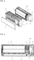
- Fig. 2 is an exploded perspective view illustrating components of the indoor unit 103 of the air-conditioning apparatus 100 according to Embodiment 1 of the present invention.
- Fig. 3 is a front view illustrating the indoor unit 103 of the air-conditioning apparatus 100 according to Embodiment 1 of the present invention, with a panel 8 of the indoor unit 103 detached from the indoor unit 103.
- the indoor unit 103 of the air-conditioning apparatus 100 is a wall mounted unit that is cuboid.
- the indoor unit 103 includes a housing 12 as an outer peripheral portion of the indoor unit 103.
- the indoor unit 103 includes the panel 8, a grille 9, a box 10, and a vane 11 that form the housing 12.
- the indoor heat exchanger 7, a drain pan 13, and an electrical component box 14 are provided in the housing 12 of the indoor unit 103.
- the indoor heat exchanger 7 is provided in space from an upper region of the inside of the housing 12 to a central region of the inside, and causes heat exchange to be performed between water and indoor air.
- the indoor heat exchanger 7 is formed in such a manner as to have a cross section formed in the shape of a mountain from a front side of the indoor heat exchanger 7 to a back side thereof.
- the fan In space located inward of the indoor heat exchanger 7 having such a cross section, the fan (not illustrated) is provided.
- the fan (not illustrated) is, for example, a cross-flow fan.
- the drain pan 13 is provided below the indoor heat exchanger 7 to receive condensation water generated at a surface of the indoor heat exchanger 7.
- the drain pan 13 has a bottom 13a that is wider than a horizontal surface of the indoor heat exchanger 7 and that receives condensation water.
- the bottom 13a of the drain pan 13 extends to a position located below a pipe unit 15 that will be described later and is provided rightward of the indoor heat exchanger 7 as viewed from the front in the figure.
- the drain pan 13 receives condensation water generated at surfaces of a first manifold pipe 16, a second manifold pipe 17, and a plurality of branch pipes 18 that will be described below and that are provided in the pipe unit 15.
- the drain pan 13 receives water let out from a hose 19 that will be described later and is provided in the pipe unit 15.
- condensed water received at the bottom 13a is made to flow out from an exhaust outlet (not illustrated) to the outside of the indoor unit 103.
- the electrical component box 14 is waterproofed and hermetically houses a control module, a control circuit board (not illustrated) that control the indoor unit 103, and other components.
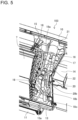
- Fig. 4 is a vertical sectional view that illustrates the indoor unit 103 of the air-conditioning apparatus 100 according to Embodiment 1 of the present invention, with the panel 8 of the indoor unit 103 detached from the indoor unit 103, and that is taken along line Z-Z in Fig. 3 .
- Fig. 5 is an enlarged perspective view illustrating the pipe unit 15 of the indoor unit 103 of the air-conditioning apparatus 100 according to Embodiment 1 of the present invention, with the panel 8 of the indoor unit 103 detached from the indoor unit 103.
- Fig. 6 is an enlarged front view illustrating the pipe unit 15 of the indoor unit 103 of the air-conditioning apparatus 100 according to Embodiment 1 of the present invention, with the panel 8 of the indoor unit 103 detached from the indoor unit 103.
- the pipe unit 15 is provided between the indoor heat exchanger 7 and the electrical component box 14.
- the pipe unit 15 includes an air vent valve 20, the hose 19, the plurality of branch pipes 18, the first manifold pipe 16, the second manifold pipe 17, and a heat insulating pipe 21.
- the air vent valve 20 allows air to escape from a water passage in the water circuit 105 that allows water to flow in the indoor heat exchanger 7.
- the air vent valve 20 is provided at an end portion on the front side of an air vent pipe 22 connected to the second manifold pipe 17.
- the hose 19 is formed of soft material that is material of a rubber tube such as a PVC tube, and has flexibility.
- the hose 19 is attached to the air vent valve 20.
- the hose 19 extends toward the drain pan 13 that is provided to receive condensed water generated in the indoor heat exchanger 7 and also extends in such a manner as to circumvent the plurality of branch pipes 18, the first manifold pipe 16, and the second manifold pipe 17.
- the air vent valve 20 When the air vent valve 20 is opened to escape air, the hose 19 lets out air along with water from the water passage in the water circuit 105 to the drain pan 13.
- the hose 19 has a double-pipe structure and an upper end portion of the hose 19 is fixed to the air vent valve 20. The hose 19 will be described in detail later.
- the plurality of branch pipes 18 are pipes that allow water to flow into the indoor heat exchanger 7 or allow water to flow out of the indoor heat exchanger 7.
- a branch pipe 18a of the plurality of branch pipes 18 is connected to the indoor heat exchanger 7 and the first manifold pipe 16 and allows water to flow between the indoor heat exchanger 7 and the first manifold pipe 16.
- a branch pipe 18b of the plurality of branch pipes 18 is connected to the indoor heat exchanger 7 and the second manifold pipe 17 and allows water to flow between the indoor heat exchanger 7 and the second manifold pipe 17.
- water cooled by the outdoor unit 101 of the air-conditioning apparatus 100 flows into the branch pipe 18a of the plurality of branch pipes 18 through the first manifold pipe 16, and then flows from the branch pipe 18a into the indoor heat exchanger 7.
- the water subjected to heat exchange at the indoor heat exchanger 7 flows into the branch pipe 18b of the plurality of branch pipes 18, and flows from the branch pipe 18b into the second manifold pipe 17.
- water heated by the outdoor unit 101 of the air-conditioning apparatus 100 flows into the branch pipe 18b through the second manifold pipe 17, and then flows from the branch pipe 18b into the indoor heat exchanger 7.
- the water subjected to heat exchange at the indoor heat exchanger 7 flows into the branch pipe 18b, and then flows from the branch pipe 18b into the first manifold pipe 16.
- the plurality of branch pipes 18 are variously bent in the pipe unit 15. As designed, the plurality of bent branch pipes 18 are connected to respective heat transfer pipes of the indoor heat exchanger 7 (which are not illustrated) at respective connection positions. The relationship between the hose 19 and the plurality of branch pipes 18 will be described later.
- the first manifold pipe 16 is connected to the branch pipe 18a of the plurality of branch pipes 18.
- the first manifold pipe 16 allows water that is to be supplied to the indoor heat exchanger 7 during the cooling operation to flow through the first manifold pipe 16. Also, the first manifold pipe 16 allows water subjected to heat exchange at the indoor heat exchanger 7 during the heating operation to flow through the first manifold pipe 16.
- the second manifold pipe 17 is connected to the branch pipe 18b of the plurality of branch pipes 18.
- the second manifold pipe 17 allows water that flows out of the indoor heat exchanger 7 during the cooling operation to flow through the second manifold pipe 17.
- the second manifold pipe 17 allows water that is to be supplied to the indoor heat exchanger 7 during the heating operation to flow through the second manifold pipe 17.
- the flow direction of water during the cooling operation and that during the heating operation may be reversed.
- the first manifold pipe 16 and the second manifold pipe 17 extend in an up-and-down direction on the right side of the indoor heat exchanger 7 and are arranged in parallel with each other. Also, as viewed from the front side, the air vent valve 20 and the hose 19 are provided between the first manifold pipe 16 and the second manifold pipe 17.
- the heat insulating pipe 21 holds both the first manifold pipe 16 and the second manifold pipe 17, and extends from indoor space to outdoor space.
- the heat insulating pipe 21 insulates the first manifold pipe 16 and the second manifold pipe 17 to prevent the first manifold pipe 16 and the second manifold pipe 17 from being affected by heat from the outside of the first manifold pipe 16 and the second manifold pipe 17.
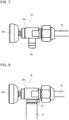
- Fig. 7 is a side view of the air vent valve 20 in the indoor unit 103 of the air-conditioning apparatus 100 according to Embodiment 1 of the present invention.
- the air vent valve 20 includes a main body 20a, a knob 20b, and an exhaust outlet portion 20c.
- the main body 20a of the air vent valve 20 is connected to the end portion on the front side of the air vent pipe 22.
- the knob 20b is provided integrally with a valve body 20d that is screwed into the main body 20a on the front side of the main body 20a such that the valve body 20d is rotatable.
- the knob 20b includes a display unit (not illustrated) that indicates opening/closing of the air vent valve 20.
- the knob 20b is discoid. By rotating the knob 20b in a circumferential direction, that is, in a clockwise direction or a counter-clockwise direction, the valve body 20d is moved toward the front side or the back side, and the air vent valve 20 can thus be opened or closed.
- the exhaust outlet 20c is located at a lower end portion of the main body 20a and is an opening that faces downwards.
- the upper end portion of the hose 19 is attached to the exhaust outlet 20c.
- Fig. 8 is a side view illustrating the air vent valve 20 in the indoor unit 103 of the air-conditioning apparatus 100 according to Embodiment 1 of the present invention, with the hose 19 fixed to the air vent valve 20.
- Fig. 9 is a vertical sectional view illustrating the air vent valve 20 in the indoor unit 103 of the air-conditioning apparatus 100 according to Embodiment 1 of the present invention, with the hose 19 fixed to the air vent valve 20.
- the hose 19 has the double-wall structure, and includes an inner exhaust pipe 19a and an outer protection pipe 19b.
- the inner exhaust pipe 19a and the outer protection pipe 19b are formed of the same material having flexibility.
- the inner exhaust pipe 19a is directly fitted onto the exhaust outlet 20c of the air vent valve 20.
- the inner exhaust pipe 19a is provided in the outer protection pipe 19b.
- the outer protection pipe 19b is located outward of the inner exhaust pipe 19a fitted on the exhaust outlet 20c of the air vent valve 20.
- a cylindrical gap 19c is provided between an outer circumferential portion of the inner exhaust pipe 19a and an inner circumferential portion of the outer protection pipe 19b.
- the inner exhaust pipe 19a and the outer protection pipe 19b are fitted onto the exhaust outlet 20c of the air vent valve 20 and held in such a state.
- the inner exhaust pipe 19a and the outer protection pipe 19b are fixed to the exhaust outlet 20c by a binding band 23.
- the inner exhaust pipe 19a may be fixed to the exhaust outlet 20c by an adhesive
- the outer protection pipe 19b may be fixed to the inner exhaust pipe 19a by an adhesive
- Fig. 10 is an enlarged vertical sectional view of a distal end of a lower end portion 19d of the hose 19 and the drain pan 13 according to Embodiment 1 of the present invention. As illustrated in Fig. 10 , the distal end of the lower end portion 19d of the hose 19 has an end face that is inclined relative to a horizontal direction.
- the end face of the distal end of the lower end portion 19d of the hose 19 may be parallel to the horizontal direction. However, in this case, the distal end of the lower end portion 19d of the hose 19 is not satisfactorily drained dry.
- a gap S is provided between the distal end of the lower end portion 19d of the hose 19 and the bottom 13a of the drain pan 1.
- the gap S is provided to cause sound to be made when water that flows out of the distal end of the lower end portion 19d of the hose 19 strikes the bottom 13a of the drain pan 13.
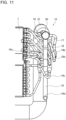
- Fig. 11 is an enlarged front view illustrating the hose 19, the plurality of branch pipes 18, the first manifold pipe 16, and the second manifold pipe 17 in Embodiment 1 of the present invention.
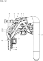
- Fig. 12 is an enlarged side view illustrating the hose 19, the plurality of branch pipes 18, the first manifold pipe 16, and the second manifold pipe 17 in Embodiment 1 of the present invention.
- a branch pipe 18c of the plurality of branch pipes 18 is bent around the hose 19 and holds the hose 19.
- the branch pipe 18c that holds the hose 19 is located in a lower portion of the housing 12.
- the branch pipe 18c extends from a distal end of a lower end portion of the second manifold pipe 17.
- the lowermost one of the plurality of branch pipes 18 is the branch pipe 18c that holds the hose 19.
- the number of branch pipes 18c holding the hose 19 is one, but is not limited to one. That is, a plurality of branch pipes 18c may be provided to hold the hose 19.
- the position of the branch pipe 18c holding the hose 19 is not limited. It is preferable that the branch pipe 18c holding the hose 19 be connected to one of the first manifold pipe 16 and the second manifold pipe 17 that is further from the indoor heat exchanger 7 than the other.
- a branch pipe 18d of the plurality of branch pipes 18 that is located in an upper portion of the housing 12 is in contact with the hose 19 on a back side of the hose 19.
- the branch pipe 18d is extended toward the front side and is bent toward a connection position with the heat transfer pipe of the indoor heat exchanger 7.
- the branch pipe 18d is in contact with the hose 19 on a back side of the hose 19. Therefore, the branch pipe 18c holds the hose 19 that is in contact with the branch pipe 18d in the upper portion of the housing 12 and extends downwards, such that the distal end of the lower end portion 19d is located in an inner space in the drain pan 13.
- the air vent valve 20 may be located closer to the front side than in the above configuration such that the hose 19 is not in contact with the branch pipe 18d in the upper portion of the housing 12.
- the indoor unit 103 cannot made smaller; that is, this configuration is thus applicable only in the case where the housing 12 of the indoor unit 103 has sufficient space for provision of components.
- the indoor unit 103 of the air-conditioning apparatus 100 includes the indoor heat exchanger 7 provided in the housing 12 as a heat-medium heat exchanger that transfers heat between indoor air and water that is a heat medium.
- the indoor unit 103 includes the air vent valve 20 that allows air to escape from the water passage in the water circuit 105 that causes water to flow in the indoor heat exchanger 7.
- the indoor unit 103 includes the drain pan 13 that is provided below the indoor heat exchanger 7 to receive condensation water generated at the surface of the indoor heat exchanger 7.
- the indoor unit 103 includes the hose 19 that has flexibility, is attached to the air vent valve 20, and lets out air along with water from the water passage to the inner space in the drain pan 13.
- the hose 19 has a double-wall structure and the upper end portion of the hose 19 is fixed to the air vent valve 20.
- the hose 19 has the double-wall structure and the upper end portion of the hose 19 is fixed to the air vent valve 20. It is therefore possible to improve the stiffness of the hose 19 and to increase the weight of the hose 19. Thus, the hose 19 hardly collapses and is easily hung downwards. Therefore, the lower portion of the hose 19 can maintain a cross section necessary for letting out air, the hose 19 is not blocked up and thus allows the flow of water, and the distal end of the lower end portion 19d of the hose 19 does not move uncontrollably, whereby water can be smoothly let out from the hose 19. That is, it is possible to prevent the distal end of the lower end portion 19d of the air vent hose 19 from uncontrollably moving without adding an extra component and changing the simple structure of the air bent hose 19.
- the other can be kept fixed to the air vent valve 20 at the upper portion of the other.
- water does not directly flow out from the exhaust outlet 20c of the air vent valve 20, with the hose 19 not attached to the exhaust outlet 20c, and water does not fly off to the vicinity of the exhaust outlet 20c.
- the hose 19 has the double-wall structure and the upper end portion of the hose 19 is fixed to the air vent valve 20, even if the hose 19 is bent from an upper side of the hose 19 to the lower side of the hose 19 in such a manner as to circumvent the plurality of branch pipes 18, only the outer protection pipe 19b that is an outer one of the pipes in the hose 19 having the double-wall structure is deformed, the inner exhaust pipe 19a that is an inner one of the pipes in the hose 19 can maintain a cross section necessary for letting out air and water from the hose 19, the hose 19 is not blocked up and thus allows the flow of water, and the distal end of the lower end portion 19d of the hose 19 does not move uncontrollably, whereby water can be smoothly let out from the hose 19.
- the indoor unit 103 of the air-conditioning apparatus 100 includes the indoor heat exchanger 7 that is provided in the housing 12 as a heat-medium heat exchanger that causes heat exchange to be performed between indoor air and water that is a heat medium.
- the indoor unit 103 includes the air vent valve 20 that allows air to escape from the water passage in the water circuit 105 that causes water to flow in the indoor heat exchanger 7.
- the indoor unit 103 includes the drain pan 13 that is provided below the indoor heat exchanger 7 to receive condensation water generated at the surface of the indoor heat exchanger 7.
- the indoor unit 103 includes the hose 19 that has flexibility, is attached to the air vent valve 20, and lets out air along with water from the water passage to the inner space in the drain pan 13.
- the indoor unit 103 includes the plurality of branch pipes 18 that allow water to flow into the indoor heat exchanger 7 or allow water to flow out of the indoor heat exchanger 7. At least one branch pipe 18c of the plurality of branch pipes 18 is bent around the hose 19 and holds the hose 19.
- At least the one branch pipe 18c is bent around the hose 19 and holds the hose 19.
- the lower portion of the hose 19 can maintain a cross section required to let out air along with water.
- the hose 19 is not blocked up and thus allows the flow of water, and the distal end of the lower end portion 19d of the hose 19 does not move uncontrollably, whereby water can be smoothly let out from the hose 19.
- No further fixing component is added, and at least one branch pipe 18c serves to allow water to flow into the indoor heat exchanger 7 and also hold the hose 19. Therefore, it is possible to prevent the distal end of the lower end portion 19d of the hose 19 from moving uncontrollably without changing the simple structure and adding an extra component.
- a heat medium such as water or brine, which is not refrigerant, is supplied to the indoor heat exchanger 7.
- the branch pipe 18c that holds the hose 19 is located in the lower portion of the housing 12.
- At least one branch pipe 18c is bent around the lower portion of the hose 19 and holds the hose 19.
- the lower portion of the hose 19 that is held by the branch pipe 18c can maintain a cross section required to let out air and water.
- the hose 19 is not blocked up and thus allows the flow of water, and the distal end of the lower end portion 19d of the hose 19 does not move uncontrollably, whereby water can be smoothly let out.
- No further fixing component is added, and at least one branch pipe 18c serves to allow water to flow into the indoor heat exchanger 7 and also hold the hose 19. It is therefore possible to prevent the distal end of the lower end portion 19d of the hose 19 from moving uncontrollably without changing the simple structure and adding an extra component.
- the branch pipe 18d of the plurality of branch pipes 18 that is located in the upper portion of the housing 12 is in contact with the hose 19 on the back side of the hose 19.
- the branch pipe 18c holds the hose 19 that is in contact with the branch pipe 18d located in the upper portion of the housing 12 and extends downwards, such that the distal end of the lower end portion 19d of the hose 19 is located in the inner space in the drain pan 13.
- the branch pipe 18c holds the hose 19 that is in contact with the branch pipe 18d located in the upper portion of the housing 12 and extends downwards, such that the distal end of the lower end portion 19d is located in the inner space in the drain pan 13.
- the hose 19 extends through space located inward of a bent portion of the branch pipe 18c that holds the hose 19, and the hose 19 is forcibly bent such that the distal end of the lower end portion 19d is located in the inner space in the drain pan 13. Therefore, the hose 19 is not blocked up and thus allows the flow of water, and the distal end of the lower end portion 19d of the hose 19 does not move uncontrollably, whereby water can be smoothly let out from the hose 19. Furthermore, no further fixing component is added, and at least one branch pipe 18c serves to allow water to flow in the indoor heat exchanger 7 and hold the hose 19. That is, it is possible to prevent the distal end of the lower end portion 19d of the hose 19 from moving uncontrollably without changing the simple structure of the hose 19 and adding an extra component.
- the hose 19 is in contact with at least two of the plurality of branch pipes 18, that is, the hose 19 is in contact with the branch pipe 18d in the upper portion of the housing 12, and is also in contact with the branch pipe 18c that holds the hose 19 at a location where the hose 19 is located in the space located inward of the bent portion of the branch pipe 18c.
- the hose 19 can be firmly and stably held such that the state of the hose 19 is maintained in a position thereof in a further firm and stable manner.
- the hose 19 has the double-wall structure and the upper end portion of the hose 19 is fixed to the air vent valve 20, even if the hose 19 is bent from the upper portion of the hose 19 to the lower portion of the hose 19, only the outer protection pipe 19b that is the outer one of the pipes provided in the hose 19 having the double-wall structure is deformed, and at least the inner exhaust pipe 19a that is the inner one of the pipes provided in the hose 19 can maintain a cross section required to let out air and water from the hose 19.
- the hose 19 is not blocked up and thus allows the flow of water, and the distal end pf the lower end portion 19d of the hose 19 does not move uncontrollably, whereby water can be smoothly let out from the hose 19.
- the number of branch pipes 18c holding the hose 19 is one.
- the hose 19 is attached in the final step of an assembly procedure of the indoor unit 103.
- the hose 19 needs to be passed through the space located inward of the bent portion of the branch pipe 18c that holds the hose 19. Therefore, since the number of branch pipes 18c holding the hose 19 is one, the number of times the hose 19 is passed through the space located inward of the bent portion of the branch pipe 18c is also one, and the indoor unit 103 can thus be easily assembled.
- the indoor unit 103 of the air-conditioning apparatus 100 includes the first manifold pipe 16 that is connected to the branch pipe 18a of the plurality of branch pipes 18 and allows water that is to be supplied to the indoor heat exchanger 7 or allows water that flows out of the indoor heat exchanger 7 to flow through the first manifold pipe 16.
- the indoor unit 103 includes the second manifold pipe 17 that is connected to the branch pipe 18b of the plurality of branch pipes 18 and allows water that flows out of the indoor heat exchanger 7 or flow that is to be supplied to the indoor heat exchanger 7 to flow through the second manifold pipe 17.
- the first manifold pipe 16 and the second manifold pipe 17 are located beside the indoor heat exchanger 7 to extend in the up-and-down direction and are disposed side by side as viewed from the front side.
- the air vent valve 20 and the hose 19 are located between the first manifold pipe 16 and the second manifold pipe 17 as viewed from the front side.
- the air vent valve 20 and the hose 19 can be provided in an empty region of space that is other than regions of the space in which the first manifold pipe 16 and the second manifold pipe 17 are provided. Therefore, in order to provide the air vent valve 20 and the hose 19, it is not necessary to increase the size of the indoor unit 103. Thus, the indoor unit 103 can be made smaller than existing indoor units.
- the branch pipe 18c that holds the hose 19 is connected to one of the first manifold pipe 16 and the second manifold pipe 17 that is located further from the indoor heat exchanger 7 from the other.
- the branch pipe 18c that holds the hose 19 is connected to one of the first manifold pipe 16 and the second manifold pipe 17 that is located further from the indoor heat exchanger 7 than the other.
- the branch pipe 18c that holds the hose 19 can be elongated to connect to the indoor heat exchanger 7, and the inner space of the indoor unit 103 can be effectively used.
- Embodiment 1 in the hose 19 provided in the indoor unit 103 of the air-conditioning apparatus 100, the end face of the distal end of the lower end portion 19d is inclined relative to the horizontal direction.
- an edge of the inclined end face of the distal end of the lower end portion 19d of the hose 19 is sharp, and water is satisfactorily drained dry without collecting, and water can be effectively let out from the hose 19.
- the gap S is provided between the distal end of the lower end portion 19d of the hose 19 and the bottom 13a of the drain pan 13.
- the gap S is provided between the distal end of the lower end portion 19d of the hose 19 and the bottom 13a of the drain pan 13.
- the lower end portion 19d of the hose 19 does not come into contact with the bottom 13a of the drain pan 13, and the hose 19 can thus be prevented from being bent and also being blocked up. Therefore, it is possible to prevent the lower end portion 19d of the hose 19 from being blocked up and to smoothly let out water from the hose 19.
- the air-conditioning apparatus 100 includes the indoor unit 103 for the air-conditioning apparatus 100.
- the wall-mounted indoor unit 103 is described above.
- the indoor unit 103 is not limited to such a type of indoor unit.
- the indoor unit 103 of the air-conditioning apparatus 100 according to the embodiment of the present invention can also be applied as a floor-standing type indoor unit, a ceiling concealed type indoor unit, etc.
Description
- The present disclosure relates to an indoor unit of an air-conditioning apparatus that includes an air vent valve and to the air-conditioning apparatus.
- Conventionally, for example, when an indoor unit is installed, air is mixed in a heat medium in a heat medium passage. As a result, in a heat-medium heat exchanger, the flow of the heat medium is obstructed, or the efficiency of heat exchange is reduced. As a countermeasure against such a problem, air in the heat medium passage is escaped from the heat medium passage.
- In an air escape from the heat medium passage, air that flows in an air-vent hose connected to an air vent valve that is in an opened state is caused to escape along with a heat medium from the heat medium passage. A distal end of a lower end portion of the hose is accommodated in a drain pan that is provided to receive condensed water generated from the heat-medium heat exchanger during the operation of the indoor unit. Thus, the heat medium that flows along with the air out of the heat medium passage during the air escape is collected in the inner space in the drain pan, and is then made to flow out of the drain pan to the outside of the indoor unit.
- The number of hoses prepared for the above purpose is one (see, for example, Patent Literature 1).
JPH09210392A DE202010010532U1 discloses an air guide tube. - Patent Literature 1:
Japanese Unexamined Patent Application Publication No. 9-210392 - In the case where the hose is provided in space in which a plurality of branch pipes connected to the heat-medium heat exchanger are irregularly arranged, the hose is bent in such a manner as to circumvent the branch pipes. Therefore, the hose is formed of soft material that is material of a rubber tube such as a PVC tube, and has flexibility. However, the air vent hose may be greatly deformed. In such a case, a lower portion of the hose cannot maintain a cross section necessary for letting out air from the hose, the hose is blocked up not to allow the flow of a heat medium, and the distal end of the lower end portion of the hose thus moves uncontrollably.
- To prevent the distal end of the lower end portion of the hose from moving uncontrollably, the hose may be fixed by a fixing member. However, if the fixing member is further added into the space in which the plurality of branch pipes are irregularly arranged, an extra space for provision of the fixing member is required, and the number of components increases.
- The embodiment of the present invention has been made to solve the above problems, and the present disclosure relates to an indoor unit of an air-conditioning apparatus and an air-conditioning apparatus, in which a distal end of a lower end portion of an air vent hose can be prevented from moving uncontrollably, without changing a simple structure of the hose and also without adding an extra component. Solution to Problem
- An indoor unit of an air-conditioning apparatus according to the present invention is disclosed in independent claim 1 and in dependent claims 2-9.
- An air-conditioning apparatus according to the present invention is disclosed in
claim 10 and includes the indoor unit of the air-conditioning apparatus of any of claims 1 to 9. - In the indoor unit of the air-conditioning apparatus and the air-conditioning apparatus according to the present invention, the distal end of the lower end portion of the air vent hose can be prevented from moving uncontrollably, without changing the simple structure of the hose and also without adding an extra component.
-
- [
Fig. 1] Fig. 1 illustrates an outline configuration of an air-conditioning apparatus according to Embodiment 1 of the present invention. - [
Fig. 2] Fig. 2 is an exploded perspective view illustrating components of an indoor unit of the air-conditioning apparatus according to Embodiment 1 of the present invention. - [
Fig. 3] Fig. 3 is a front view illustrating the indoor unit of the air-conditioning apparatus according to Embodiment 1 of the present invention, with a panel of the indoor unit detached from the indoor unit. - [
Fig. 4] Fig. 4 is a vertical sectional view that illustrates the indoor unit of the air-conditioning apparatus according to Embodiment 1 of the present invention, with the panel of the indoor unit detached from the indoor unit, and that is taken along line Z-Z inFig. 3 . - [
Fig. 5] Fig. 5 is an enlarged perspective view illustrating a pipe unit of the indoor unit of the air-conditioning apparatus according to Embodiment 1 of the present invention, with the panel of the indoor unit detached from the indoor unit. - [
Fig. 6] Fig. 6 is an enlarged front view illustrating the pipe unit of the indoor unit of the air-conditioning apparatus according to Embodiment 1 of the present invention, with the panel of the indoor unit detached from the indoor unit. - [
Fig. 7] Fig. 7 is a side view of an air vent valve in the indoor unit of the air-conditioning apparatus according to Embodiment 1 of the present invention. - [
Fig. 8] Fig. 8 is a side view illustrating the air vent valve in the indoor unit of the air-conditioning apparatus according to Embodiment 1 of the present invention, with a hose fixed to the air vent valve. - [
Fig. 9] Fig. 9 is a vertical sectional view illustrating the air vent valve in the indoor unit of the air-conditioning apparatus according to Embodiment 1 of the present invention, with the hose fixed to the air vent valve. - [
Fig. 10] Fig. 10 is an enlarged vertical sectional view of a distal end of a lower end portion of the hose and a drain pan according to Embodiment 1 of the present invention. - [
Fig. 11] Fig. 11 is an enlarged front view including the hose, a plurality of branch pipes, a first manifold pipe, and a second manifold pipe in Embodiment 1 of the present invention. - [
Fig. 12] Fig. 12 is an enlarged side view illustrating the hose, the plurality of branch pipes, the first manifold pipe, and the second manifold pipe in Embodiment 1 of the present invention. - An embodiment of the present invention will be described with reference to the drawings. In each of the figures, components that are the same as or equivalent to those in a previous figure are denoted by the same reference signs. The same is true of the entire text of the specification. In each of sectional views, hatching is omitted as appropriate for viewability. Configurations of components that are described in the entire text of the specification are merely examples, that is, the configurations of the components are not limited to the described configurations.
-
Fig. 1 is a schematic configuration view of an air-conditioning apparatus 100 according to Embodiment 1 of the present invention. The air-conditioning apparatus 100 as illustrated inFig. 1 includes anoutdoor unit 101, arelay unit 102, and anindoor unit 103. - The
outdoor unit 101 and therelay unit 102 form arefrigerant circuit 104. Therefrigerant circuit 104 includes a compressor 1, a four-way valve 2, anoutdoor heat exchanger 3, an expansion valve 4, and a heat-transfer heat exchanger 5. - The
relay unit 102 and theindoor unit 103 form awater circuit 105 as a heat medium circuit. Non-flammable material such as water or brine is used as a heat medium. The following description is made by referring to the case where water is used as the heat medium. Thewater circuit 105 includes the heat-transfer heat exchanger 5, apump 6, and anindoor heat exchanger 7 that serves as a heat-medium heat exchanger. - The
outdoor unit 101 includes the compressor 1, the four-way valve 2, theoutdoor heat exchanger 3, and the expansion valve 4. Theoutdoor unit 101 includes a fan (not illustrated) provided to promote heat exchange between outdoor air and refrigerant at theoutdoor heat exchanger 3. Theoutdoor unit 101 includes a control unit (not illustrated) that controls the compressor 1, the four-way valve 2, the expansion valve 4, the fan, etc. - The compressor 1 compresses sucked refrigerant and then discharges the refrigerant. The four-
way valve 2 switches the flow of the refrigerant in accordance with whether a cooling operation or a heating operation is performed. Theoutdoor heat exchanger 3 causes heat exchange to be performed between outdoor air and the refrigerant. Theoutdoor heat exchanger 3 operates as a condenser during the cooling operation, and condenses and liquifies the refrigerant. Theoutdoor heat exchanger 3 operates as an evaporator during the heating operation, and gasifies and evaporates the refrigerant. The expansion valve 4 regulates the pressure of the refrigerant and expands the refrigerant. Therefrigerant circuit 104 of theoutdoor unit 101 sends refrigerant that holds heat as such as cooling energy or heating energy to therelay unit 102. - The
relay unit 102 includes the heat-transfer heat exchanger 5 and thepump 6. The heat-transfer heat exchanger 5 transfers heat such as cooling energy or heating energy of refrigerant that flows in therefrigerant circuit 104 to water that flows in thewater circuit 105. The heat-transfer heat exchanger 5 operates as an evaporator during the cooling operation, and gasifies and evaporates the refrigerant. The heat-transfer heat exchanger 5 operates as a condenser during the heating operation, and condenses and liquifies the refrigerant. Thepump 6 regulates the amount of the water that flows in thewater circuit 105. Therelay unit 102 includes a control unit (not illustrated) that controls thepump 6. - The
indoor unit 103 includes theindoor heat exchanger 7 that causes heat exchange to be performed between water and indoor air. Theindoor unit 103 includes a fan (not illustrated) provided to promote heat exchange between water and indoor air at theindoor heat exchanger 7. Theindoor unit 103 includes a control unit (not illustrated) that controls the fan and other components. - The
outdoor unit 101, therelay unit 102, and theindoor unit 103 include respective control units as described above. However, these control units may be combined into a single control unit, and the single control unit may be provided at any one of theoutdoor unit 101, therelay unit 102, and theindoor unit 103. Alternatively, the control units may be kept separate from each other, or some of them may be combined, such that the control units are provided at respective units or selected ones of the units. Each of the control units includes a storage unit that stores a program and a central processing unit (CPU) that executes processing according to the program. - Because of the above configuration of the air-
conditioning apparatus 100, the operation of the air-conditioning apparatus 100 can be switched from one of the cooling operation and the heating operation to the other by switching the flow of the refrigerant using the four-way valve 2 of theoutdoor unit 101. -
Fig. 2 is an exploded perspective view illustrating components of theindoor unit 103 of the air-conditioning apparatus 100 according to Embodiment 1 of the present invention. -
Fig. 3 is a front view illustrating theindoor unit 103 of the air-conditioning apparatus 100 according to Embodiment 1 of the present invention, with apanel 8 of theindoor unit 103 detached from theindoor unit 103. - As illustrated in
Figs. 2 and 3 , theindoor unit 103 of the air-conditioning apparatus 100 is a wall mounted unit that is cuboid. Theindoor unit 103 includes ahousing 12 as an outer peripheral portion of theindoor unit 103. To be more specific, theindoor unit 103 includes thepanel 8, agrille 9, abox 10, and avane 11 that form thehousing 12. In thehousing 12 of theindoor unit 103, theindoor heat exchanger 7, adrain pan 13, and anelectrical component box 14 are provided. - The
indoor heat exchanger 7 is provided in space from an upper region of the inside of thehousing 12 to a central region of the inside, and causes heat exchange to be performed between water and indoor air. Theindoor heat exchanger 7 is formed in such a manner as to have a cross section formed in the shape of a mountain from a front side of theindoor heat exchanger 7 to a back side thereof. In space located inward of theindoor heat exchanger 7 having such a cross section, the fan (not illustrated) is provided. The fan (not illustrated) is, for example, a cross-flow fan. - The
drain pan 13 is provided below theindoor heat exchanger 7 to receive condensation water generated at a surface of theindoor heat exchanger 7. Thedrain pan 13 has a bottom 13a that is wider than a horizontal surface of theindoor heat exchanger 7 and that receives condensation water. The bottom 13a of thedrain pan 13 extends to a position located below apipe unit 15 that will be described later and is provided rightward of theindoor heat exchanger 7 as viewed from the front in the figure. Thedrain pan 13 receives condensation water generated at surfaces of afirst manifold pipe 16, asecond manifold pipe 17, and a plurality ofbranch pipes 18 that will be described below and that are provided in thepipe unit 15. Thedrain pan 13 receives water let out from ahose 19 that will be described later and is provided in thepipe unit 15. In thedrain pan 13, for example, condensed water received at the bottom 13a is made to flow out from an exhaust outlet (not illustrated) to the outside of theindoor unit 103. - The
electrical component box 14 is waterproofed and hermetically houses a control module, a control circuit board (not illustrated) that control theindoor unit 103, and other components. -
Fig. 4 is a vertical sectional view that illustrates theindoor unit 103 of the air-conditioning apparatus 100 according to Embodiment 1 of the present invention, with thepanel 8 of theindoor unit 103 detached from theindoor unit 103, and that is taken along line Z-Z inFig. 3 .Fig. 5 is an enlarged perspective view illustrating thepipe unit 15 of theindoor unit 103 of the air-conditioning apparatus 100 according to Embodiment 1 of the present invention, with thepanel 8 of theindoor unit 103 detached from theindoor unit 103.Fig. 6 is an enlarged front view illustrating thepipe unit 15 of theindoor unit 103 of the air-conditioning apparatus 100 according to Embodiment 1 of the present invention, with thepanel 8 of theindoor unit 103 detached from theindoor unit 103. - As illustrated in
Figs. 4 to 6 , in theindoor unit 103, thepipe unit 15 is provided between theindoor heat exchanger 7 and theelectrical component box 14. Thepipe unit 15 includes anair vent valve 20, thehose 19, the plurality ofbranch pipes 18, thefirst manifold pipe 16, thesecond manifold pipe 17, and aheat insulating pipe 21. - The
air vent valve 20 allows air to escape from a water passage in thewater circuit 105 that allows water to flow in theindoor heat exchanger 7. Theair vent valve 20 is provided at an end portion on the front side of anair vent pipe 22 connected to thesecond manifold pipe 17. - The
hose 19 is formed of soft material that is material of a rubber tube such as a PVC tube, and has flexibility. Thehose 19 is attached to theair vent valve 20. Thehose 19 extends toward thedrain pan 13 that is provided to receive condensed water generated in theindoor heat exchanger 7 and also extends in such a manner as to circumvent the plurality ofbranch pipes 18, thefirst manifold pipe 16, and thesecond manifold pipe 17. When theair vent valve 20 is opened to escape air, thehose 19 lets out air along with water from the water passage in thewater circuit 105 to thedrain pan 13. Thehose 19 has a double-pipe structure and an upper end portion of thehose 19 is fixed to theair vent valve 20. Thehose 19 will be described in detail later. - The plurality of
branch pipes 18 are pipes that allow water to flow into theindoor heat exchanger 7 or allow water to flow out of theindoor heat exchanger 7. Abranch pipe 18a of the plurality ofbranch pipes 18 is connected to theindoor heat exchanger 7 and thefirst manifold pipe 16 and allows water to flow between theindoor heat exchanger 7 and thefirst manifold pipe 16. Abranch pipe 18b of the plurality ofbranch pipes 18 is connected to theindoor heat exchanger 7 and thesecond manifold pipe 17 and allows water to flow between theindoor heat exchanger 7 and thesecond manifold pipe 17. - During the cooling operation, water cooled by the
outdoor unit 101 of the air-conditioning apparatus 100 flows into thebranch pipe 18a of the plurality ofbranch pipes 18 through thefirst manifold pipe 16, and then flows from thebranch pipe 18a into theindoor heat exchanger 7. The water subjected to heat exchange at theindoor heat exchanger 7 flows into thebranch pipe 18b of the plurality ofbranch pipes 18, and flows from thebranch pipe 18b into thesecond manifold pipe 17. - During the heating operation, water heated by the
outdoor unit 101 of the air-conditioning apparatus 100 flows into thebranch pipe 18b through thesecond manifold pipe 17, and then flows from thebranch pipe 18b into theindoor heat exchanger 7. The water subjected to heat exchange at theindoor heat exchanger 7 flows into thebranch pipe 18b, and then flows from thebranch pipe 18b into thefirst manifold pipe 16. - The plurality of
branch pipes 18 are variously bent in thepipe unit 15. As designed, the plurality ofbent branch pipes 18 are connected to respective heat transfer pipes of the indoor heat exchanger 7 (which are not illustrated) at respective connection positions. The relationship between thehose 19 and the plurality ofbranch pipes 18 will be described later. - The
first manifold pipe 16 is connected to thebranch pipe 18a of the plurality ofbranch pipes 18. Thefirst manifold pipe 16 allows water that is to be supplied to theindoor heat exchanger 7 during the cooling operation to flow through thefirst manifold pipe 16. Also, thefirst manifold pipe 16 allows water subjected to heat exchange at theindoor heat exchanger 7 during the heating operation to flow through thefirst manifold pipe 16. - The
second manifold pipe 17 is connected to thebranch pipe 18b of the plurality ofbranch pipes 18. Thesecond manifold pipe 17 allows water that flows out of theindoor heat exchanger 7 during the cooling operation to flow through thesecond manifold pipe 17. Also, thesecond manifold pipe 17 allows water that is to be supplied to theindoor heat exchanger 7 during the heating operation to flow through thesecond manifold pipe 17. - In the
first manifold pipe 16 and thesecond manifold pipe 17, the flow direction of water during the cooling operation and that during the heating operation may be reversed. - As viewed from the front side, the
first manifold pipe 16 and thesecond manifold pipe 17 extend in an up-and-down direction on the right side of theindoor heat exchanger 7 and are arranged in parallel with each other. Also, as viewed from the front side, theair vent valve 20 and thehose 19 are provided between thefirst manifold pipe 16 and thesecond manifold pipe 17. - The
heat insulating pipe 21 holds both thefirst manifold pipe 16 and thesecond manifold pipe 17, and extends from indoor space to outdoor space. Theheat insulating pipe 21 insulates thefirst manifold pipe 16 and thesecond manifold pipe 17 to prevent thefirst manifold pipe 16 and thesecond manifold pipe 17 from being affected by heat from the outside of thefirst manifold pipe 16 and thesecond manifold pipe 17. -
Fig. 7 is a side view of theair vent valve 20 in theindoor unit 103 of the air-conditioning apparatus 100 according to Embodiment 1 of the present invention. Theair vent valve 20 includes amain body 20a, aknob 20b, and anexhaust outlet portion 20c. - The
main body 20a of theair vent valve 20 is connected to the end portion on the front side of theair vent pipe 22. Theknob 20b is provided integrally with avalve body 20d that is screwed into themain body 20a on the front side of themain body 20a such that thevalve body 20d is rotatable. Theknob 20b includes a display unit (not illustrated) that indicates opening/closing of theair vent valve 20. Theknob 20b is discoid. By rotating theknob 20b in a circumferential direction, that is, in a clockwise direction or a counter-clockwise direction, thevalve body 20d is moved toward the front side or the back side, and theair vent valve 20 can thus be opened or closed. Theexhaust outlet 20c is located at a lower end portion of themain body 20a and is an opening that faces downwards. The upper end portion of thehose 19 is attached to theexhaust outlet 20c. - When the
air vent valve 20 is opened, at thepipe unit 15, air and water in the water passage flow into thepipe unit 15 from theair vent pipe 22 that communicates with thesecond manifold pipe 17, and the air flows along with the water out of the water passage through theexhaust outlet 20c. -
Fig. 8 is a side view illustrating theair vent valve 20 in theindoor unit 103 of the air-conditioning apparatus 100 according to Embodiment 1 of the present invention, with thehose 19 fixed to theair vent valve 20.Fig. 9 is a vertical sectional view illustrating theair vent valve 20 in theindoor unit 103 of the air-conditioning apparatus 100 according to Embodiment 1 of the present invention, with thehose 19 fixed to theair vent valve 20. - As illustrated in
Figs. 8 and9 , thehose 19 has the double-wall structure, and includes aninner exhaust pipe 19a and anouter protection pipe 19b. Theinner exhaust pipe 19a and theouter protection pipe 19b are formed of the same material having flexibility. Theinner exhaust pipe 19a is directly fitted onto theexhaust outlet 20c of theair vent valve 20. Theinner exhaust pipe 19a is provided in theouter protection pipe 19b. Thus, theouter protection pipe 19b is located outward of theinner exhaust pipe 19a fitted on theexhaust outlet 20c of theair vent valve 20. Between an outer circumferential portion of theinner exhaust pipe 19a and an inner circumferential portion of theouter protection pipe 19b, acylindrical gap 19c is provided. - The
inner exhaust pipe 19a and theouter protection pipe 19b are fitted onto theexhaust outlet 20c of theair vent valve 20 and held in such a state. Theinner exhaust pipe 19a and theouter protection pipe 19b are fixed to theexhaust outlet 20c by a bindingband 23. - Regarding the fixation of the
inner exhaust pipe 19a and theouter protection pipe 19b, theinner exhaust pipe 19a may be fixed to theexhaust outlet 20c by an adhesive, and theouter protection pipe 19b may be fixed to theinner exhaust pipe 19a by an adhesive. -
Fig. 10 is an enlarged vertical sectional view of a distal end of alower end portion 19d of thehose 19 and thedrain pan 13 according to Embodiment 1 of the present invention. As illustrated inFig. 10 , the distal end of thelower end portion 19d of thehose 19 has an end face that is inclined relative to a horizontal direction. - The end face of the distal end of the
lower end portion 19d of thehose 19 may be parallel to the horizontal direction. However, in this case, the distal end of thelower end portion 19d of thehose 19 is not satisfactorily drained dry. - Between the distal end of the
lower end portion 19d of thehose 19 and the bottom 13a of the drain pan 1, a gap S is provided. The gap S is provided to cause sound to be made when water that flows out of the distal end of thelower end portion 19d of thehose 19 strikes the bottom 13a of thedrain pan 13. -
Fig. 11 is an enlarged front view illustrating thehose 19, the plurality ofbranch pipes 18, thefirst manifold pipe 16, and thesecond manifold pipe 17 in Embodiment 1 of the present invention.Fig. 12 is an enlarged side view illustrating thehose 19, the plurality ofbranch pipes 18, thefirst manifold pipe 16, and thesecond manifold pipe 17 in Embodiment 1 of the present invention. - As illustrated in
Figs. 11 and12 , abranch pipe 18c of the plurality ofbranch pipes 18 is bent around thehose 19 and holds thehose 19. Thebranch pipe 18c that holds thehose 19 is located in a lower portion of thehousing 12. To be more specific, thebranch pipe 18c extends from a distal end of a lower end portion of thesecond manifold pipe 17. The lowermost one of the plurality ofbranch pipes 18 is thebranch pipe 18c that holds thehose 19. - It should be noted that the number of
branch pipes 18c holding thehose 19 is one, but is not limited to one. That is, a plurality ofbranch pipes 18c may be provided to hold thehose 19. In addition, the position of thebranch pipe 18c holding thehose 19 is not limited. It is preferable that thebranch pipe 18c holding thehose 19 be connected to one of thefirst manifold pipe 16 and thesecond manifold pipe 17 that is further from theindoor heat exchanger 7 than the other. - In contrast, a
branch pipe 18d of the plurality ofbranch pipes 18 that is located in an upper portion of thehousing 12 is in contact with thehose 19 on a back side of thehose 19. Thebranch pipe 18d is extended toward the front side and is bent toward a connection position with the heat transfer pipe of theindoor heat exchanger 7. Thus, thebranch pipe 18d is in contact with thehose 19 on a back side of thehose 19. Therefore, thebranch pipe 18c holds thehose 19 that is in contact with thebranch pipe 18d in the upper portion of thehousing 12 and extends downwards, such that the distal end of thelower end portion 19d is located in an inner space in thedrain pan 13. - The
air vent valve 20 may be located closer to the front side than in the above configuration such that thehose 19 is not in contact with thebranch pipe 18d in the upper portion of thehousing 12. However, in such a configuration, theindoor unit 103 cannot made smaller; that is, this configuration is thus applicable only in the case where thehousing 12 of theindoor unit 103 has sufficient space for provision of components. - According to Embodiment 1, the
indoor unit 103 of the air-conditioning apparatus 100 includes theindoor heat exchanger 7 provided in thehousing 12 as a heat-medium heat exchanger that transfers heat between indoor air and water that is a heat medium. Theindoor unit 103 includes theair vent valve 20 that allows air to escape from the water passage in thewater circuit 105 that causes water to flow in theindoor heat exchanger 7. Theindoor unit 103 includes thedrain pan 13 that is provided below theindoor heat exchanger 7 to receive condensation water generated at the surface of theindoor heat exchanger 7. Theindoor unit 103 includes thehose 19 that has flexibility, is attached to theair vent valve 20, and lets out air along with water from the water passage to the inner space in thedrain pan 13. Thehose 19 has a double-wall structure and the upper end portion of thehose 19 is fixed to theair vent valve 20. - In the above configuration, the
hose 19 has the double-wall structure and the upper end portion of thehose 19 is fixed to theair vent valve 20. It is therefore possible to improve the stiffness of thehose 19 and to increase the weight of thehose 19. Thus, thehose 19 hardly collapses and is easily hung downwards. Therefore, the lower portion of thehose 19 can maintain a cross section necessary for letting out air, thehose 19 is not blocked up and thus allows the flow of water, and the distal end of thelower end portion 19d of thehose 19 does not move uncontrollably, whereby water can be smoothly let out from thehose 19. That is, it is possible to prevent the distal end of thelower end portion 19d of theair vent hose 19 from uncontrollably moving without adding an extra component and changing the simple structure of the airbent hose 19. - In the
hose 19, even if one of theinner exhaust pipe 19a and theouter protection pipe 19b is detached from the airbent valve 20, the other can be kept fixed to theair vent valve 20 at the upper portion of the other. Thus, water does not directly flow out from theexhaust outlet 20c of theair vent valve 20, with thehose 19 not attached to theexhaust outlet 20c, and water does not fly off to the vicinity of theexhaust outlet 20c. - Furthermore, since the
hose 19 has the double-wall structure and the upper end portion of thehose 19 is fixed to theair vent valve 20, even if thehose 19 is bent from an upper side of thehose 19 to the lower side of thehose 19 in such a manner as to circumvent the plurality ofbranch pipes 18, only theouter protection pipe 19b that is an outer one of the pipes in thehose 19 having the double-wall structure is deformed, theinner exhaust pipe 19a that is an inner one of the pipes in thehose 19 can maintain a cross section necessary for letting out air and water from thehose 19, thehose 19 is not blocked up and thus allows the flow of water, and the distal end of thelower end portion 19d of thehose 19 does not move uncontrollably, whereby water can be smoothly let out from thehose 19. - According to Embodiment 1, the
indoor unit 103 of the air-conditioning apparatus 100 includes theindoor heat exchanger 7 that is provided in thehousing 12 as a heat-medium heat exchanger that causes heat exchange to be performed between indoor air and water that is a heat medium. Theindoor unit 103 includes theair vent valve 20 that allows air to escape from the water passage in thewater circuit 105 that causes water to flow in theindoor heat exchanger 7. Theindoor unit 103 includes thedrain pan 13 that is provided below theindoor heat exchanger 7 to receive condensation water generated at the surface of theindoor heat exchanger 7. Theindoor unit 103 includes thehose 19 that has flexibility, is attached to theair vent valve 20, and lets out air along with water from the water passage to the inner space in thedrain pan 13. Theindoor unit 103 includes the plurality ofbranch pipes 18 that allow water to flow into theindoor heat exchanger 7 or allow water to flow out of theindoor heat exchanger 7. At least onebranch pipe 18c of the plurality ofbranch pipes 18 is bent around thehose 19 and holds thehose 19. - In the above configuration, at least the one
branch pipe 18c is bent around thehose 19 and holds thehose 19. Thus, the lower portion of thehose 19 can maintain a cross section required to let out air along with water. Furthermore, thehose 19 is not blocked up and thus allows the flow of water, and the distal end of thelower end portion 19d of thehose 19 does not move uncontrollably, whereby water can be smoothly let out from thehose 19. No further fixing component is added, and at least onebranch pipe 18c serves to allow water to flow into theindoor heat exchanger 7 and also hold thehose 19. Therefore, it is possible to prevent the distal end of thelower end portion 19d of thehose 19 from moving uncontrollably without changing the simple structure and adding an extra component. - A heat medium such as water or brine, which is not refrigerant, is supplied to the
indoor heat exchanger 7. Thus, even if at least onebranch pipe 18c is long in such a manner as to be bent around thehose 19 and to surround and hold thehose 19, the design heat efficiency of theindoor heat exchanger 7 is not decreased. - In Embodiment 1, in the
indoor unit 103 of the air-conditioning apparatus 100, thebranch pipe 18c that holds thehose 19 is located in the lower portion of thehousing 12. - In the above configuration, at least one
branch pipe 18c is bent around the lower portion of thehose 19 and holds thehose 19. Thus, the lower portion of thehose 19 that is held by thebranch pipe 18c can maintain a cross section required to let out air and water. Furthermore, thehose 19 is not blocked up and thus allows the flow of water, and the distal end of thelower end portion 19d of thehose 19 does not move uncontrollably, whereby water can be smoothly let out. No further fixing component is added, and at least onebranch pipe 18c serves to allow water to flow into theindoor heat exchanger 7 and also hold thehose 19. It is therefore possible to prevent the distal end of thelower end portion 19d of thehose 19 from moving uncontrollably without changing the simple structure and adding an extra component. - According to Embodiment 1, in the
indoor unit 103 of the air-conditioning apparatus 100, thebranch pipe 18d of the plurality ofbranch pipes 18 that is located in the upper portion of thehousing 12 is in contact with thehose 19 on the back side of thehose 19. Thebranch pipe 18c holds thehose 19 that is in contact with thebranch pipe 18d located in the upper portion of thehousing 12 and extends downwards, such that the distal end of thelower end portion 19d of thehose 19 is located in the inner space in thedrain pan 13. - In the configuration, the
branch pipe 18c holds thehose 19 that is in contact with thebranch pipe 18d located in the upper portion of thehousing 12 and extends downwards, such that the distal end of thelower end portion 19d is located in the inner space in thedrain pan 13. Thus, even if a stress acts on thehose 19 to move the lower portion of thehose 19 outwards such that the distal end of thelower end portion 19d is moved out of the inner space in thedrain pan 13, the distal end of thelower end portion 19d is kept located in the inner space in thedrain pan 13. This is because thehose 19 extends through space located inward of a bent portion of thebranch pipe 18c that holds thehose 19, and thehose 19 is forcibly bent such that the distal end of thelower end portion 19d is located in the inner space in thedrain pan 13. Therefore, thehose 19 is not blocked up and thus allows the flow of water, and the distal end of thelower end portion 19d of thehose 19 does not move uncontrollably, whereby water can be smoothly let out from thehose 19. Furthermore, no further fixing component is added, and at least onebranch pipe 18c serves to allow water to flow in theindoor heat exchanger 7 and hold thehose 19. That is, it is possible to prevent the distal end of thelower end portion 19d of thehose 19 from moving uncontrollably without changing the simple structure of thehose 19 and adding an extra component. - The
hose 19 is in contact with at least two of the plurality ofbranch pipes 18, that is, thehose 19 is in contact with thebranch pipe 18d in the upper portion of thehousing 12, and is also in contact with thebranch pipe 18c that holds thehose 19 at a location where thehose 19 is located in the space located inward of the bent portion of thebranch pipe 18c. Thus, thehose 19 can be firmly and stably held such that the state of thehose 19 is maintained in a position thereof in a further firm and stable manner. - Moreover, since the
hose 19 has the double-wall structure and the upper end portion of thehose 19 is fixed to theair vent valve 20, even if thehose 19 is bent from the upper portion of thehose 19 to the lower portion of thehose 19, only theouter protection pipe 19b that is the outer one of the pipes provided in thehose 19 having the double-wall structure is deformed, and at least theinner exhaust pipe 19a that is the inner one of the pipes provided in thehose 19 can maintain a cross section required to let out air and water from thehose 19. Thus, thehose 19 is not blocked up and thus allows the flow of water, and the distal end pf thelower end portion 19d of thehose 19 does not move uncontrollably, whereby water can be smoothly let out from thehose 19. - In Embodiment 1, in the
indoor unit 103 of the air-conditioning apparatus 100, the number ofbranch pipes 18c holding thehose 19 is one. - In the above configuration, the
hose 19 is attached in the final step of an assembly procedure of theindoor unit 103. At this time, after fixed to theair vent valve 20, thehose 19 needs to be passed through the space located inward of the bent portion of thebranch pipe 18c that holds thehose 19. Therefore, since the number ofbranch pipes 18c holding thehose 19 is one, the number of times thehose 19 is passed through the space located inward of the bent portion of thebranch pipe 18c is also one, and theindoor unit 103 can thus be easily assembled. - In Embodiment 1, the
indoor unit 103 of the air-conditioning apparatus 100 includes thefirst manifold pipe 16 that is connected to thebranch pipe 18a of the plurality ofbranch pipes 18 and allows water that is to be supplied to theindoor heat exchanger 7 or allows water that flows out of theindoor heat exchanger 7 to flow through thefirst manifold pipe 16. Theindoor unit 103 includes thesecond manifold pipe 17 that is connected to thebranch pipe 18b of the plurality ofbranch pipes 18 and allows water that flows out of theindoor heat exchanger 7 or flow that is to be supplied to theindoor heat exchanger 7 to flow through thesecond manifold pipe 17. Thefirst manifold pipe 16 and thesecond manifold pipe 17 are located beside theindoor heat exchanger 7 to extend in the up-and-down direction and are disposed side by side as viewed from the front side. Theair vent valve 20 and thehose 19 are located between thefirst manifold pipe 16 and thesecond manifold pipe 17 as viewed from the front side. - In the configuration, the
air vent valve 20 and thehose 19 can be provided in an empty region of space that is other than regions of the space in which thefirst manifold pipe 16 and thesecond manifold pipe 17 are provided. Therefore, in order to provide theair vent valve 20 and thehose 19, it is not necessary to increase the size of theindoor unit 103. Thus, theindoor unit 103 can be made smaller than existing indoor units. - In Embodiment 1, in the
indoor unit 103 of the air-conditioning apparatus 100, thebranch pipe 18c that holds thehose 19 is connected to one of thefirst manifold pipe 16 and thesecond manifold pipe 17 that is located further from theindoor heat exchanger 7 from the other. - In the above configuration, the
branch pipe 18c that holds thehose 19 is connected to one of thefirst manifold pipe 16 and thesecond manifold pipe 17 that is located further from theindoor heat exchanger 7 than the other. Thus, while being bent smoothly, thebranch pipe 18c that holds thehose 19 can be elongated to connect to theindoor heat exchanger 7, and the inner space of theindoor unit 103 can be effectively used. - In Embodiment 1, in the
hose 19 provided in theindoor unit 103 of the air-conditioning apparatus 100, the end face of the distal end of thelower end portion 19d is inclined relative to the horizontal direction. - In the above configuration, an edge of the inclined end face of the distal end of the
lower end portion 19d of thehose 19 is sharp, and water is satisfactorily drained dry without collecting, and water can be effectively let out from thehose 19. - In Embodiment 1, in the
indoor unit 103 of the air-conditioning apparatus 100, the gap S is provided between the distal end of thelower end portion 19d of thehose 19 and the bottom 13a of thedrain pan 13. - In the above configuration, the gap S is provided between the distal end of the
lower end portion 19d of thehose 19 and the bottom 13a of thedrain pan 13. Thus, in the case where theair vent valve 20 is opened and water is let out from thehose 19, when dropping onto the bottom 13a of thedrain pan 13 through the gap S, the water makes noise of striking the bottom 13a of thedrain pan 13. Because of such a noise, an operator can confirm that theair vent valve 20 is in the opened state. It is therefore possible to prevent the operator from forgetting to close theair vent valve 20 and to prevent water from being uselessly let out. - Because provision of the gap S between the distal end of the
lower end portion 19d of thehose 19 and the bottom 13a of thedrain pan 13, thelower end portion 19d of thehose 19 does not come into contact with the bottom 13a of thedrain pan 13, and thehose 19 can thus be prevented from being bent and also being blocked up. Therefore, it is possible to prevent thelower end portion 19d of thehose 19 from being blocked up and to smoothly let out water from thehose 19. - In Embodiment 1, the air-
conditioning apparatus 100 includes theindoor unit 103 for the air-conditioning apparatus 100. - In the above configuration, it is possible to prevent the distal end of the
lower end portion 19d of theair vent hose 19 from moving uncontrollably without changing the simple structure of thehose 19 and adding an extra component. - With respect to the above embodiment, the wall-mounted
indoor unit 103 is described above. However, theindoor unit 103 is not limited to such a type of indoor unit. Theindoor unit 103 of the air-conditioning apparatus 100 according to the embodiment of the present invention can also be applied as a floor-standing type indoor unit, a ceiling concealed type indoor unit, etc. - 1 compressor, 2 four-way valve, 3 outdoor heat exchanger, 4 expansion valve, 5 heat-transfer heat exchanger, 6 pump, 7 indoor heat exchanger, 8 panel, 9 grille, 10 box, 11 vane, 12 housing, 13 drain pan, 13a bottom, 14 electrical component box, 15 pipe unit, 16 first manifold pipe, 17 second manifold pipe, 18 branch pipe, 18a branch pipe, 18b branch pipe, 18c branch pipe, 18d branch pipe, 19 hose, 19a inner exhaust pipe, 19b outer protection pipe, 19c gap, 19d lower end portion, 20 air vent valve, 20a main body, 20b knob, 20c exhaust outlet, 20d valve body, 21 heat insulating pipe, 22 air vent pipe, 23 binding band, 100 air-conditioning apparatus, 101 outdoor unit, 102 relay unit, 103 indoor unit, 104 refrigerant circuit, 105 water circuit
Claims (10)
- An indoor unit (103) of an air-conditioning apparatus (100) comprising:a heat-medium heat exchanger (7) provided in a housing (12) and configured to cause heat exchange to be performed between a heat medium and indoor air;an air vent valve (20) configured to allow air to escape from a heat medium passage that allows the heat medium to flow in the heat-medium heat exchanger (7);a drain pan (13) provided below the heat-medium heat exchanger (7) and configured to receive condensation water generated at a surface of the heat-medium heat exchanger (7);a hose (19) having flexibility, attached to the air vent valve (20), and configured to let out the air along with the heat medium from the heat medium passage to an inner space in the drain pan (13), andthe indoor unit (103) being characterized by that:the hose (19) has a double-wall structure in which an inner exhaust pipe (19a) and an outer protection pipe (19b) are provided, and an upper end portion of the hose (19) is fixed to the air vent valve (20),wherein the inner exhaust pipe (19a) and the outer protection pipe (19b) are formed of the same flexible material, andwherein the inner exhaust pipe (19a) and the outer protection pipe (19b) are provided such that a cylindrical gap (19c) is provided between an outer circumferential portion of the inner exhaust pipe (19a) and an inner circumferential portion of the outer protection pipe (19b).
- The indoor unit (103) of the air-conditioning apparatus (100) of claim 1, further comprising:a plurality of branch pipes (18) configured to allow the heat medium to flow into the heat-medium heat exchanger (7) or allow the heat medium to flow out of the heat-medium heat exchanger (7),wherein at least one (18c) of the plurality of branch pipes (18) is bent around the hose (19) and holds the hose (19).
- The indoor unit (103) of the air-conditioning apparatus (100) of claim 2,
wherein the at least one branch pipe (18c) that holds the hose (19) is located in a lower portion of the housing (12). - The indoor unit (103) of the air-conditioning apparatus (100) of claim 2 or 3,wherein of the plurality of branch pipes (18), a branch pipe (18d) located in an upper portion of the housing (12) is in contact with the hose (19) on a back side of the hose (19), andwherein the at least one branch pipe (18c) that holds the hose (19) holds the hose (19) such that a distal end of a lower end portion (19d) of the hose (19) is located in the inner space in the drain pan (13).
- The indoor unit (103) of the air-conditioning apparatus (100) of any one of claims 2 to 4,
wherein the at least one branch pipe (18c) that holds the hose (19) is a single branch pipe. - The indoor unit (103) of the air-conditioning apparatus (100) of any one of claims 2 to 5, further comprising:a first manifold pipe (16) connected to one of the plurality of branch pipes (18) and configured to allow a heat medium that is to be supplied to the heat-medium heat exchanger (7) to flow though the first manifold pipe (16) or allow a heat medium that flows out of heat-medium heat exchanger (7) to flow through the first manifold pipe (16); anda second manifold pipe (17) connected to another one of the plurality of branch pipes (18) and configured to allow the heat medium that flows out of the heat-medium heat exchanger (7) to flow through the second manifold pipe (17) or allow the heat medium that is to be supplied to the heat-medium heat exchanger (7) to flow through the second manifold pipe (17),wherein the first manifold pipe (16) and the second manifold pipe (17) are arranged beside the heat-medium heat exchanger (7) in such a manner as to extend in an up-and-down direction, and are provided side by side as viewed in front view, andwherein the air vent valve (20) and the hose (19) are located between the first manifold pipe (16) and the second manifold pipe (17) as viewed in front view.
- The indoor unit (103) of the air-conditioning apparatus (100) of claim 6,
wherein the at least one branch pipe (18c) that holds the hose (19) is connected to one of the first manifold pipe (16) and the second manifold pipe (17) that is located further from the heat-medium heat exchanger (7) than the other of the first manifold pipe (16) and the second manifold pipe (17). - The indoor unit (103) of the air-conditioning apparatus (100) of any one of claims 1 to 7,
wherein in the hose (19), the distal end of the lower end portion (19d) has an end face that is inclined relative to a horizontal direction. - The indoor unit (103) of the air-conditioning apparatus (100) of any one of claims 1 to 8,
wherein a gap (S) is provided between the distal end of the lower end portion (19d) of the hose (19) and a bottom of the drain pan (13). - An air-conditioning apparatus (100) comprising:
the indoor unit (103) of the air-conditioning apparatus (100) of any one of claims 1 to 9.
Applications Claiming Priority (1)
| Application Number | Priority Date | Filing Date | Title |
|---|---|---|---|
| PCT/JP2017/044197 WO2019111406A1 (en) | 2017-12-08 | 2017-12-08 | Indoor unit of air conditioning apparatus, and air conditioning apparatus |
Publications (3)
| Publication Number | Publication Date |
|---|---|
| EP3722682A1 EP3722682A1 (en) | 2020-10-14 |
| EP3722682A4 EP3722682A4 (en) | 2020-11-25 |
| EP3722682B1 true EP3722682B1 (en) | 2023-10-11 |
Family
ID=66750140
Family Applications (1)
| Application Number | Title | Priority Date | Filing Date |
|---|---|---|---|
| EP17933984.1A Active EP3722682B1 (en) | 2017-12-08 | 2017-12-08 | Indoor unit of air conditioning apparatus, and air conditioning apparatus |
Country Status (5)
| Country | Link |
|---|---|
| US (1) | US11592192B2 (en) |
| EP (1) | EP3722682B1 (en) |
| JP (1) | JP6865854B2 (en) |
| CN (1) | CN111433519A (en) |
| WO (1) | WO2019111406A1 (en) |
Families Citing this family (1)
| Publication number | Priority date | Publication date | Assignee | Title |
|---|---|---|---|---|
| US11674741B2 (en) * | 2019-12-20 | 2023-06-13 | Johnson Controls Tyco IP Holdings LLP | Drain spout for drain of HVAC system |
Citations (1)
| Publication number | Priority date | Publication date | Assignee | Title |
|---|---|---|---|---|
| EP2463594B1 (en) * | 2010-01-08 | 2016-01-06 | Daikin Industries, Ltd. | Air evacuation device, heat exchange unit and fixing tool |
Family Cites Families (18)
| Publication number | Priority date | Publication date | Assignee | Title |
|---|---|---|---|---|
| JPS56126020U (en) * | 1980-02-27 | 1981-09-25 | ||
| JPS6132894U (en) | 1984-07-31 | 1986-02-27 | 史朗 金尾 | drain hose |
| JPS6132984U (en) * | 1984-07-31 | 1986-02-27 | 株式会社島津製作所 | Radiation detector for ECT |
| JPS6334922U (en) * | 1986-08-20 | 1988-03-07 | ||
| JPH0277511U (en) * | 1988-12-01 | 1990-06-14 | ||
| JP2642820B2 (en) * | 1991-11-25 | 1997-08-20 | 三洋電機株式会社 | Air conditioner |
| JPH06257776A (en) * | 1993-03-02 | 1994-09-16 | Matsushita Electric Ind Co Ltd | Drain hose |
| JPH09210392A (en) * | 1996-01-30 | 1997-08-12 | Daikin Ind Ltd | Fan coil unit |
| DE202005010328U1 (en) * | 2005-07-01 | 2005-09-15 | Da Kunststoff Gmbh | Device for connecting branch pipe from mains into house pipes has flexible structural unit with centre section of corrugated piping for flexibility and with two rigid end sections functioning as pipe connectors |
| WO2008086489A2 (en) * | 2007-01-10 | 2008-07-17 | Karamanos John C | Embedded heat exchanger for heating, ventilation, and air conditioning (hvac) systems and methods |
| DE202010010532U1 (en) * | 2010-07-22 | 2010-10-21 | Reventa Gmbh & Co. Kg | Air guide tube |
| US20180045343A1 (en) * | 2010-10-19 | 2018-02-15 | Contitech Techno-Chemie Gmbh | Fluid resistant high temperature hose |
| US20120247601A1 (en) * | 2011-03-28 | 2012-10-04 | Glenn Allen Ayers | Flexible Hose During Pressurization |
| CN202083046U (en) * | 2011-05-26 | 2011-12-21 | 姜鉴明 | Efficient counterflow reverse-return coil-type heat exchanger |
| JP2012247131A (en) | 2011-05-27 | 2012-12-13 | Mitsubishi Electric Corp | Air harmonizer |
| CN202220913U (en) * | 2011-08-18 | 2012-05-16 | 永亨控股集团有限公司 | FRPP high strength reinforcement pipe |
| CN205534654U (en) * | 2016-04-20 | 2016-08-31 | 浙江光通塑业有限公司 | Plastics drain pipe |
| CN206591743U (en) * | 2017-01-17 | 2017-10-27 | 深圳市清华苑建筑与规划设计研究有限公司 | A kind of big depth large scale concrete roof building looks for pitched roof drain structure |
-
2017
- 2017-12-08 WO PCT/JP2017/044197 patent/WO2019111406A1/en unknown
- 2017-12-08 EP EP17933984.1A patent/EP3722682B1/en active Active
- 2017-12-08 JP JP2019557970A patent/JP6865854B2/en active Active
- 2017-12-08 CN CN201780097446.2A patent/CN111433519A/en active Pending
- 2017-12-08 US US16/652,529 patent/US11592192B2/en active Active
Patent Citations (1)
| Publication number | Priority date | Publication date | Assignee | Title |
|---|---|---|---|---|
| EP2463594B1 (en) * | 2010-01-08 | 2016-01-06 | Daikin Industries, Ltd. | Air evacuation device, heat exchange unit and fixing tool |
Also Published As
| Publication number | Publication date |
|---|---|
| EP3722682A1 (en) | 2020-10-14 |
| JPWO2019111406A1 (en) | 2020-07-09 |
| US20200240651A1 (en) | 2020-07-30 |
| WO2019111406A1 (en) | 2019-06-13 |
| US11592192B2 (en) | 2023-02-28 |
| EP3722682A4 (en) | 2020-11-25 |
| JP6865854B2 (en) | 2021-04-28 |
| CN111433519A (en) | 2020-07-17 |
Similar Documents
| Publication | Publication Date | Title |
|---|---|---|
| JP5811134B2 (en) | Air conditioner indoor unit | |
| EP3361172B1 (en) | Indoor unit and air conditioner | |
| EP3379156B1 (en) | Air conditioner | |
| JP2014215013A (en) | Decorative laminate panel and air conditioner indoor unit | |
| EP3722682B1 (en) | Indoor unit of air conditioning apparatus, and air conditioning apparatus | |
| JP5123018B2 (en) | Air conditioner | |
| WO2007012157A1 (en) | Condensate drain hose arrangement for an evaporator unit | |
| EP3392573B1 (en) | Outdoor machine for freezing cycle apparatus | |
| EP3091302B1 (en) | Indoor unit and air conditioner | |
| JP4702273B2 (en) | Insulated piping structure of air conditioner | |
| EP4083531A1 (en) | Air conditioner | |
| CN111148947B (en) | Indoor unit of air conditioner and air conditioner | |
| EP3851758B1 (en) | Air conditioner | |
| WO2017203680A1 (en) | Cooling unit | |
| JP2010078219A (en) | Floor type air conditioner | |
| JP6070390B2 (en) | Air conditioner indoor unit | |
| KR20050064963A (en) | The supporting structure of pipe for duct type air-conditioner | |
| WO2021064442A1 (en) | Indoor unit for an air conditioner | |
| JP2023173582A (en) | Air conditioning indoor unit, and air conditioning device | |
| KR200396503Y1 (en) | Ceiling Air-Conditioner | |
| US20190078816A1 (en) | Convertible case horizontal refrigeration coil | |
| JP5425034B2 (en) | Air conditioner indoor unit | |
| JP2004020078A (en) | Air conditioner | |
| JP2009243840A (en) | Indoor unit and air conditioner | |
| JP2003222366A (en) | Indoor unit and air conditioner |
Legal Events
| Date | Code | Title | Description |
|---|---|---|---|
| STAA | Information on the status of an ep patent application or granted ep patent |
Free format text: STATUS: THE INTERNATIONAL PUBLICATION HAS BEEN MADE |
|
| PUAI | Public reference made under article 153(3) epc to a published international application that has entered the european phase |
Free format text: ORIGINAL CODE: 0009012 |
|
| STAA | Information on the status of an ep patent application or granted ep patent |
Free format text: STATUS: REQUEST FOR EXAMINATION WAS MADE |
|
| 17P | Request for examination filed |
Effective date: 20200603 |
|
| AK | Designated contracting states |
Kind code of ref document: A1 Designated state(s): AL AT BE BG CH CY CZ DE DK EE ES FI FR GB GR HR HU IE IS IT LI LT LU LV MC MK MT NL NO PL PT RO RS SE SI SK SM TR |
|
| AX | Request for extension of the european patent |
Extension state: BA ME |
|
| A4 | Supplementary search report drawn up and despatched |
Effective date: 20201027 |
|
| RIC1 | Information provided on ipc code assigned before grant |
Ipc: F24F 1/00 20190101AFI20201021BHEP Ipc: F24F 1/0007 20190101ALI20201021BHEP Ipc: F16L 11/20 20060101ALI20201021BHEP Ipc: F24F 5/00 20060101ALI20201021BHEP Ipc: F24F 13/22 20060101ALI20201021BHEP Ipc: F25B 49/00 20060101ALI20201021BHEP |
|
| DAV | Request for validation of the european patent (deleted) | ||
| DAX | Request for extension of the european patent (deleted) | ||
| GRAP | Despatch of communication of intention to grant a patent |
Free format text: ORIGINAL CODE: EPIDOSNIGR1 |
|
| STAA | Information on the status of an ep patent application or granted ep patent |
Free format text: STATUS: GRANT OF PATENT IS INTENDED |
|
| INTG | Intention to grant announced |
Effective date: 20230424 |
|
| GRAS | Grant fee paid |
Free format text: ORIGINAL CODE: EPIDOSNIGR3 |
|
| GRAA | (expected) grant |
Free format text: ORIGINAL CODE: 0009210 |
|
| STAA | Information on the status of an ep patent application or granted ep patent |
Free format text: STATUS: THE PATENT HAS BEEN GRANTED |
|
| AK | Designated contracting states |
Kind code of ref document: B1 Designated state(s): AL AT BE BG CH CY CZ DE DK EE ES FI FR GB GR HR HU IE IS IT LI LT LU LV MC MK MT NL NO PL PT RO RS SE SI SK SM TR |
|
| REG | Reference to a national code |
Ref country code: GB Ref legal event code: FG4D |
|
| REG | Reference to a national code |
Ref country code: CH Ref legal event code: EP |
|
| REG | Reference to a national code |
Ref country code: DE Ref legal event code: R096 Ref document number: 602017075350 Country of ref document: DE |
|
| REG | Reference to a national code |
Ref country code: IE Ref legal event code: FG4D |
|
| P01 | Opt-out of the competence of the unified patent court (upc) registered |
Effective date: 20231018 |
|
| PGFP | Annual fee paid to national office [announced via postgrant information from national office to epo] |
Ref country code: DE Payment date: 20231107 Year of fee payment: 7 |
|
| REG | Reference to a national code |
Ref country code: LT Ref legal event code: MG9D |
|
| REG | Reference to a national code |
Ref country code: NL Ref legal event code: MP Effective date: 20231011 |
|
| REG | Reference to a national code |
Ref country code: AT Ref legal event code: MK05 Ref document number: 1620571 Country of ref document: AT Kind code of ref document: T Effective date: 20231011 |
|
| PG25 | Lapsed in a contracting state [announced via postgrant information from national office to epo] |
Ref country code: NL Free format text: LAPSE BECAUSE OF FAILURE TO SUBMIT A TRANSLATION OF THE DESCRIPTION OR TO PAY THE FEE WITHIN THE PRESCRIBED TIME-LIMIT Effective date: 20231011 |
|
| PG25 | Lapsed in a contracting state [announced via postgrant information from national office to epo] |
Ref country code: GR Free format text: LAPSE BECAUSE OF FAILURE TO SUBMIT A TRANSLATION OF THE DESCRIPTION OR TO PAY THE FEE WITHIN THE PRESCRIBED TIME-LIMIT Effective date: 20240112 |
|
| PG25 | Lapsed in a contracting state [announced via postgrant information from national office to epo] |
Ref country code: IS Free format text: LAPSE BECAUSE OF FAILURE TO SUBMIT A TRANSLATION OF THE DESCRIPTION OR TO PAY THE FEE WITHIN THE PRESCRIBED TIME-LIMIT Effective date: 20240211 |
|
| PG25 | Lapsed in a contracting state [announced via postgrant information from national office to epo] |
Ref country code: LT Free format text: LAPSE BECAUSE OF FAILURE TO SUBMIT A TRANSLATION OF THE DESCRIPTION OR TO PAY THE FEE WITHIN THE PRESCRIBED TIME-LIMIT Effective date: 20231011 |