EP3722154A1 - Sliding assembly for vehicle passenger compartment - Google Patents
Sliding assembly for vehicle passenger compartment Download PDFInfo
- Publication number
- EP3722154A1 EP3722154A1 EP19168135.2A EP19168135A EP3722154A1 EP 3722154 A1 EP3722154 A1 EP 3722154A1 EP 19168135 A EP19168135 A EP 19168135A EP 3722154 A1 EP3722154 A1 EP 3722154A1
- Authority
- EP
- European Patent Office
- Prior art keywords
- bearing face
- base
- balls
- sliding assembly
- translation
- Prior art date
- Legal status (The legal status is an assumption and is not a legal conclusion. Google has not performed a legal analysis and makes no representation as to the accuracy of the status listed.)
- Granted
Links
- 238000005096 rolling process Methods 0.000 claims abstract description 11
- 239000000463 material Substances 0.000 claims abstract description 4
- NJPPVKZQTLUDBO-UHFFFAOYSA-N novaluron Chemical compound C1=C(Cl)C(OC(F)(F)C(OC(F)(F)F)F)=CC=C1NC(=O)NC(=O)C1=C(F)C=CC=C1F NJPPVKZQTLUDBO-UHFFFAOYSA-N 0.000 description 2
- 125000006850 spacer group Chemical group 0.000 description 2
- 230000000712 assembly Effects 0.000 description 1
- 238000000429 assembly Methods 0.000 description 1
- 238000006073 displacement reaction Methods 0.000 description 1
- 230000000694 effects Effects 0.000 description 1
- 229920001971 elastomer Polymers 0.000 description 1
- 239000000806 elastomer Substances 0.000 description 1
Images

Classifications
-
- B—PERFORMING OPERATIONS; TRANSPORTING
- B60—VEHICLES IN GENERAL
- B60R—VEHICLES, VEHICLE FITTINGS, OR VEHICLE PARTS, NOT OTHERWISE PROVIDED FOR
- B60R7/00—Stowing or holding appliances inside vehicle primarily intended for personal property smaller than suit-cases, e.g. travelling articles, or maps
- B60R7/04—Stowing or holding appliances inside vehicle primarily intended for personal property smaller than suit-cases, e.g. travelling articles, or maps in driver or passenger space, e.g. using racks
Definitions
- the present invention relates to a sliding assembly for a vehicle interior and to a vehicle comprising at least one such sliding assembly.
- Such an assembly comprises for example a rail which is fixed to the floor of the vehicle and a slider integral with a console where the slider is movable in translation along the rail.
- Such an assembly makes it possible to move the console along the rail in order to adjust its position.
- Such a sliding assembly conventionally comprises balls bearing against the rolling surfaces and it may happen that by force of displacement, the balls and / or the rolling surfaces undergo wear.
- An object of the present invention is to provide a sliding assembly for a vehicle interior which does not have the drawbacks of the state of the art and which, in particular, comprises means which compensate for wear clearances.
- Such a sliding assembly thus comprises means for compensating for wear of the balls or of the running surfaces.
- the first base comprises an extension which extends from the first base beyond the second base and the second base is slidably mounted along the extension.
- the first bearing face comprises a first housing
- the second bearing face comprises a second housing
- the intermediate part is housed partly in the first housing and partly in the second housing.
- the intermediate piece comprises a first stud and a second stud, each extending in a direction perpendicular between the first bearing face and the second bearing face, the first base comprises at its first bearing face a bore in which the first stud accommodates, and the second base comprises, at the level of its second bearing face, a bore in which the second stud accommodates.
- the slide comprises a third base fixed to the two first bases, the third base comprises a third bearing face, said sliding assembly comprises two third balls arranged one next to the other parallel to the direction of translation and carried free in rotation by the third bearing face, the rail has a square, the square has a first running surface and a second running surface, and each third ball is supported and rolls against the first running surface and the second running surface .
- the invention also proposes a vehicle comprising a wall, an element and a sliding assembly according to one of the preceding variants where the rail is fixed to the wall and where the element is fixed to the slide.
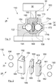
- the Fig. 1 shows a sliding assembly 100 according to the invention.
- the sliding assembly 100 comprises a rail 102 which is fixed to a wall 10 of a passenger compartment of a vehicle such as for example a vehicle floor.
- the rail 102 defines a direction of translation 20 which is here perpendicular to the plane of the sheet for the Fig. 1 .
- the Fig. 1 is a section along a plane perpendicular to the direction of translation 20.
- the sliding assembly 100 also comprises a slide 150 which is movable in translation along the rail 102 parallel to the direction of translation 20.
- the slide 150 is integral with an element 30 of the vehicle such as for example a console, a sliding window or any other element which can be moved parallel to the direction of translation 20.
- the Fig. 2 shows the slide 150 in exploded view.
- the slide 150 comprises a first base 154 which has a first bearing face 157 and a first bearing face 159 opposite the first bearing face 157.
- the first bearing face 157 and the first bearing face 159 are in planes parallel to each other. the direction of translation 20.
- the first bearing face 157 carries two first balls 156 which are arranged one next to the other parallel to the direction of translation 20.
- the first bearing face 157 comprises a hemispherical recess 165 in which the first ball 156 is arranged and free to rotate.
- the slider 150 also comprises a second base 158 which comprises a second bearing face 161 and a second bearing face 163 opposite to the second bearing face. 161.
- the second bearing face 161 and the second bearing face 163 are in planes parallel to the direction of translation 20.
- the second bearing face 161 carries two second balls 160 which are arranged one beside the other parallel to the direction of translation 20.
- the second bearing face 161 comprises a hemispherical recess 162 in which the second ball 160 is arranged and free to rotate.
- the slide 150 also comprises an intermediate part 166 which is made of a compressible material such as for example a compressible elastomer.
- the intermediate part 166 is positioned between the first bearing face 159 and the second bearing face 163 while the balls 156 and 160 are oriented opposite, that is to say outwards.
- the rail 102 comprises a U-shaped groove 170 which extends parallel to the direction of translation 20 and in which the slide 150 accommodates so that the first balls 156 are against a first branch of the U and so that the second balls 160 are against a second branch of the U.
- Each branch of the U comprises a chute 172 which has two rolling planes 174a-b which are tangent to the balls 156, 160 considered and against which said balls 156, 160 roll.
- U is here fixed to the wall 10.
- Such a slide 150 is particularly designed to operate in the case of loads oriented parallel to a first load direction 25 perpendicular to the wall 10. Such a sliding assembly 100 is therefore relatively easy to produce, compact and silent.
- the balls 156, 160 or the running surfaces 174a-b wear out, the first base 154 and the second base 158 move away from each other under the effect of the intermediate piece 166 which decompresses and compensates for the spacing of the first base 154 and of the second base 158, thus making it possible to compensate for the play introduced by wear.
- the element 30 is fixed to one of the bases 154, 158, here the first base 154.
- the first base 154 comprises an extension 180 integral with the element 30.
- the extension 180 extends from the first pedestal 154 beyond the second pedestal 158 and the latter is slidably mounted along the extension 180 when the intermediate piece 166 compresses or decompresses.
- the attachment between the extension 180 and the element 30 is carried out here by means of the spacer 32.
- the first bearing face 159 comprises a first housing 182 and the second bearing face 163 comprises a second housing 184, and the intermediate piece 166 is housed partly in the first housing 182 and partly in the second housing 184.
- the intermediate piece 166 comprises a first stud 185 and a second stud 186, each extending in a direction perpendicular between the first bearing face 159 and the second bearing face 163, and the first base 154 comprises at its first bearing face 159 a bore in which the first stud 185 accommodates, and the second base 158 comprises at the level of its second bearing face 163 has a bore in which the second stud 186 accommodates.
- the slide 150 is particularly designed to operate in the case where it also undergoes loads oriented parallel to a second direction of loads 26 parallel to the wall 10 and therefore perpendicular to the first direction of loads 25.
- the slide 150 then comprises a third base 302 which is fixed to the two first bases 154 and 158, here more particularly to the extension 180 of the first base 154.
- the element 30 is fixed to the third base 302 by means of the spacer 32.
- the third base 302 has a third bearing face 304.
- the third bearing face 304 carries two third balls 306 which are arranged one beside the other parallel to the direction of translation 20.
- the third bearing face 304 comprises a hemispherical recess 308 in which the third ball 306 is arranged and free to rotate.
- the rail 102 also comprises a bracket 310 which is here formed in part by a branch of the U constituting the groove 170.
- the bracket 310 has a first running surface 312 parallel to the direction of translation 20 and to the first direction of loads. 25 and a second rolling plane 314 parallel to the direction of translation 20 and to the second direction of loads 26.
- Each third ball 306 is supported and rolls against both the first rolling surface 312 and the second rolling surface 314.
Landscapes
- Engineering & Computer Science (AREA)
- Mechanical Engineering (AREA)
- Seats For Vehicles (AREA)
- Bearings For Parts Moving Linearly (AREA)
Abstract
L'invention concerne un ensemble coulissant (100) comportant un rail (102) s'étendant selon une direction de translation (20), un coulisseau (150) mobile en translation le long du rail (102) et comportant un premier socle (154) avec une première face portante (157) et une première face d'appui (159), deux premières billes (156) portées libres en rotation par la première face portante (157), un deuxième socle (158) avec une deuxième face portante (161) et une deuxième face d'appui (163), deux deuxièmes billes (160) portées libres en rotation par la deuxième face portante (161), une pièce intermédiaire (166) réalisée dans un matériau compressible et positionnée entre la première face d'appui (159) et la deuxième face d'appui (163), où le rail (102) comporte une rainure (170) en U dans laquelle loge le coulisseau (150) de manière à ce que les premières billes (156) soient contre une première branche du U et de manière à ce que les deuxièmes billes (160) soient contre une deuxième branche du U, et où chaque branche du U comporte une goulotte (172) présentant deux plans de roulement (174a-b) contre lesquels roulent les billes (156, 160) considérées.The invention relates to a sliding assembly (100) comprising a rail (102) extending in a direction of translation (20), a slide (150) movable in translation along the rail (102) and comprising a first base (154). ) with a first bearing face (157) and a first bearing face (159), two first balls (156) carried free in rotation by the first bearing face (157), a second base (158) with a second bearing face (161) and a second bearing face (163), two second balls (160) carried free in rotation by the second bearing face (161), an intermediate part (166) made of a compressible material and positioned between the first face bearing (159) and the second bearing face (163), where the rail (102) has a U-shaped groove (170) in which the slide (150) accommodates so that the first balls (156) are against a first branch of the U and so that the second balls (160) are against a second branch of the U, and where each branch of the U comprises a chute (172) having two rolling planes (174a-b) against which the balls (156, 160) in question roll.
Description
La présente invention concerne un ensemble coulissant pour un habitacle de véhicule ainsi qu'un véhicule comportant au moins un tel ensemble coulissant.The present invention relates to a sliding assembly for a vehicle interior and to a vehicle comprising at least one such sliding assembly.
Il est connu de mettre en oeuvre des ensembles coulissants dans un véhicule. Un tel ensemble comporte par exemple un rail qui est fixé au plancher du véhicule et un coulisseau solidaire d'une console où le coulisseau est mobile en translation le long du rail. Un tel ensemble permet de déplacer la console le long du rail afin d'ajuster sa position.It is known to implement sliding assemblies in a vehicle. Such an assembly comprises for example a rail which is fixed to the floor of the vehicle and a slider integral with a console where the slider is movable in translation along the rail. Such an assembly makes it possible to move the console along the rail in order to adjust its position.
Un tel ensemble coulissant comporte classiquement des billes en appui contre des surfaces de roulement et il peut arriver qu'à force de déplacement, les billes et/ou les surfaces de roulement subissent une usure.Such a sliding assembly conventionally comprises balls bearing against the rolling surfaces and it may happen that by force of displacement, the balls and / or the rolling surfaces undergo wear.
Une telle usure entraîne alors l'apparition de jeux qui peuvent générer des bruits.Such wear then causes the appearance of games which can generate noise.
Un objet de la présente invention est de proposer un ensemble coulissant pour un habitacle de véhicule qui ne présente pas les inconvénients de l'état de la technique et qui, en particulier, comporte des moyens qui compensent les jeux d'usure.An object of the present invention is to provide a sliding assembly for a vehicle interior which does not have the drawbacks of the state of the art and which, in particular, comprises means which compensate for wear clearances.
A cet effet, est proposé un ensemble coulissant pour habitacle de véhicule et comportant :
- un rail qui est destiné à être fixé à une paroi du véhicule et s'étendant selon une direction de translation,
- un coulisseau mobile en translation le long du rail et destiné à être solidaire d'un élément du véhicule, où le coulisseau comporte :
- un premier socle qui comporte une première face portante et une première face d'appui opposée à la première face portante,
- deux premières billes disposées l'une à côté de l'autre parallèlement à la direction de translation et portées libres en rotation par la première face portante,
- un deuxième socle qui comporte une deuxième face portante et une deuxième face d'appui opposée à la deuxième face portante,
- deux deuxièmes billes disposées l'une à côté de l'autre parallèlement à la direction de translation et portées libres en rotation par la deuxième face portante,
- une pièce intermédiaire réalisée dans un matériau compressible et positionnée entre la première face d'appui et la deuxième face d'appui,
- a rail which is intended to be fixed to a wall of the vehicle and extending in a direction of translation,
- a slide movable in translation along the rail and intended to be integral with an element of the vehicle, where the slide comprises:
- a first base which comprises a first bearing face and a first bearing face opposite the first bearing face,
- two first balls arranged one next to the other parallel to the direction of translation and carried free in rotation by the first bearing face,
- a second base which has a second bearing face and a second bearing face opposite the second bearing face,
- two second balls arranged one next to the other parallel to the direction of translation and carried free in rotation by the second bearing face,
- an intermediate piece made of a compressible material and positioned between the first bearing face and the second bearing face,
Un tel ensemble coulissant comporte ainsi des moyens pour compenser une usure des billes ou des plans de roulement.Such a sliding assembly thus comprises means for compensating for wear of the balls or of the running surfaces.
Avantageusement, le premier socle comporte une extension qui s'étend depuis le premier socle au-delà du deuxième socle et le deuxième socle est monté coulissant le long de l'extension.Advantageously, the first base comprises an extension which extends from the first base beyond the second base and the second base is slidably mounted along the extension.
Avantageusement, la première face d'appui comporte un premier logement, la deuxième face d'appui comporte un deuxième logement, et la pièce intermédiaire loge pour partie dans le premier logement et pour partie dans le deuxième logement.Advantageously, the first bearing face comprises a first housing, the second bearing face comprises a second housing, and the intermediate part is housed partly in the first housing and partly in the second housing.
Avantageusement, la pièce intermédiaire comporte un premier plot et un deuxième plot, chacun s'étend selon une direction perpendiculaire entre la première face d'appui et la deuxième face d'appui, le premier socle comporte au niveau de sa première face d'appui un alésage dans lequel loge le premier plot, et le deuxième socle comporte au niveau de sa deuxième face d'appui un alésage dans lequel loge le deuxième plot.Advantageously, the intermediate piece comprises a first stud and a second stud, each extending in a direction perpendicular between the first bearing face and the second bearing face, the first base comprises at its first bearing face a bore in which the first stud accommodates, and the second base comprises, at the level of its second bearing face, a bore in which the second stud accommodates.
Avantageusement, le coulisseau comporte un troisième socle fixé aux deux premiers socles, le troisième socle comporte une troisième face portante, ledit ensemble coulissant comporte deux troisièmes billes disposées l'une à côté de l'autre parallèlement à la direction de translation et portées libres en rotation par la troisième face portante, le rail comporte une équerre, l'équerre présente un premier plan de roulement et un deuxième plan de roulement, et chaque troisième bille est en appui et roule contre le premier plan de roulement et le deuxième plan de roulement.Advantageously, the slide comprises a third base fixed to the two first bases, the third base comprises a third bearing face, said sliding assembly comprises two third balls arranged one next to the other parallel to the direction of translation and carried free in rotation by the third bearing face, the rail has a square, the square has a first running surface and a second running surface, and each third ball is supported and rolls against the first running surface and the second running surface .
L'invention propose également un véhicule comportant une paroi, un élément et un ensemble coulissant selon l'une des variantes précédentes où le rail est fixé à la paroi et où l'élément est fixé au coulisseau.The invention also proposes a vehicle comprising a wall, an element and a sliding assembly according to one of the preceding variants where the rail is fixed to the wall and where the element is fixed to the slide.
Les caractéristiques de l'invention mentionnées ci-dessus, ainsi que d'autres, apparaîtront plus clairement à la lecture de la description suivante d'au moins un exemple de réalisation, ladite description étant faite en relation avec les dessins joints, parmi lesquels :
- [
Fig. 1 ] est une vue en coupe d'un ensemble coulissant selon l'invention, - [
Fig. 2 ] est une vue éclatée d'un coulisseau selon l'invention, et - [
Fig. 3 ] est une vue en coupe d'un ensemble coulissant selon une variante de l'invention.
- [
Fig. 1 ] is a sectional view of a sliding assembly according to the invention, - [
Fig. 2 ] is an exploded view of a slide according to the invention, and - [
Fig. 3 ] is a sectional view of a sliding assembly according to a variant of the invention.
La
L'ensemble coulissant 100 comporte un rail 102 qui est fixé à une paroi 10 d'un habitacle d'un véhicule comme par exemple un plancher du véhicule.The
Le rail 102 définit une direction de translation 20 qui est ici perpendiculaire au plan de la feuille pour la
L'ensemble coulissant 100 comporte également un coulisseau 150 qui est mobile en translation le long du rail 102 parallèlement à la direction de translation 20.The
Le coulisseau 150 est solidaire d'un élément 30 du véhicule comme par exemple une console, une vitre coulissante ou tout autre élément qui peut être déplacé parallèlement à la direction de translation 20.The
La
Le coulisseau 150 comporte un premier socle 154 qui comporte une première face portante 157 et une première face d'appui 159 opposée à la première face portante 157. La première face portante 157 et la première face d'appui 159 sont dans des plans parallèles à la direction de translation 20.The
La première face portante 157 porte deux premières billes 156 qui sont disposées l'une à côté de l'autre parallèlement à la direction de translation 20. A cette fin, dans le mode de réalisation de l'invention présenté ici, pour chaque première bille 156, la première face portante 157 comporte un évidement hémisphérique 165 dans lequel la première bille 156 est disposée et libre en rotation.The first bearing
Le coulisseau 150 comporte également un deuxième socle 158 qui comporte une deuxième face portante 161 et une deuxième face d'appui 163 opposée à la deuxième face portante 161. La deuxième face portante 161 et la deuxième face d'appui 163 sont dans des plans parallèles à la direction de translation 20.The
La deuxième face portante 161 porte deux deuxièmes billes 160 qui sont disposées l'une à côté de l'autre parallèlement à la direction de translation 20. A cette fin, dans le mode de réalisation de l'invention présenté ici, pour chaque deuxième bille 160, la deuxième face portante 161 comporte un évidement hémisphérique 162 dans lequel la deuxième bille 160 est disposée et libre en rotation.The second bearing
Le coulisseau 150 comporte également une pièce intermédiaire 166 qui est réalisée dans un matériau compressible comme par exemple un élastomère compressible. La pièce intermédiaire 166 se positionne entre la première face d'appui 159 et la deuxième face d'appui 163 tandis que les billes 156 et 160 sont orientées à l'opposé c'est-à-dire vers l'extérieur.The
Le rail 102 comporte une rainure 170 en U qui s'étend parallèlement à la direction de translation 20 et dans laquelle loge le coulisseau 150 de manière à ce que les premières billes 156 soient contre une première branche du U et de manière à ce que les deuxièmes billes 160 soient contre une deuxième branche du U. Chaque branche du U comporte une goulotte 172 qui présente deux plans de roulement 174a-b qui sont tangents aux billes 156, 160 considérées et contre lesquels roulent lesdites billes 156, 160. Le fond du U est ici fixé à la paroi 10.The
Lorsque le coulisseau 150 est introduit dans la rainure 170, les billes 156 et 160 sont en appui contre les plans de roulement 174a-b et la pièce intermédiaire 166 est écrasée tout en évitant que la première face d'appui 159 et la deuxième face d'appui 163 viennent en contact l'une avec l'autre.When the
Un tel coulisseau 150 est particulièrement prévu pour fonctionner dans le cas de charges orientées parallèlement à une première direction de charges 25 perpendiculaire à la paroi 10. Un tel ensemble coulissant 100 est donc relativement facile à réaliser, peu encombrant et silencieux. En outre, si les billes 156, 160 ou les plans de roulement 174a-b s'usent, le premier socle 154 et le deuxième socle 158 s'écartent l'un de l'autre sous l'effet de la pièce intermédiaire 166 qui se décompresse et compense l'écartement du premier socle 154 et du deuxième socle 158 permettant ainsi la compensation des jeux introduits par l'usure.Such a
L'élément 30 est fixé à l'un des socles 154, 158, ici le premier socle 154.The
A cette fin, dans le mode de réalisation de l'invention présenté à la
Pour assurer la bonne mise en place de la pièce intermédiaire 166 par rapport au premier socle 154 et au deuxième socle 158, la première face d'appui 159 comporte un premier logement 182 et la deuxième face d'appui 163 comporte un deuxième logement 184, et la pièce intermédiaire 166 loge pour partie dans le premier logement 182 et pour partie dans le deuxième logement 184.To ensure the correct positioning of the
Pour assurer un bon transfert des efforts lors de la translation du coulisseau 150 entre le premier socle 154 et le deuxième socle 158, la pièce intermédiaire 166 comporte un premier plot 185 et un deuxième plot 186, chacun s'étendant selon une direction perpendiculaire entre la première face d'appui 159 et la deuxième face d'appui 163, et le premier socle 154 comporte au niveau de sa première face d'appui 159 un alésage dans lequel loge le premier plot 185, et le deuxième socle 158 comporte au niveau de sa deuxième face d'appui 163 un alésage dans lequel loge le deuxième plot 186.To ensure good transfer of the forces during the translation of the
Dans la variante de réalisation de la
Le coulisseau 150 comporte alors un troisième socle 302 qui est fixé aux deux premiers socles 154 et 158, ici plus particulièrement à l'extension 180 du premier socle 154.The
Dans le mode de réalisation de l'invention de la
Le troisième socle 302 comporte une troisième face portante 304.The
La troisième face portante 304 porte deux troisièmes billes 306 qui sont disposées l'une à côté de l'autre parallèlement à la direction de translation 20. A cette fin, dans le mode de réalisation de l'invention présenté ici, pour chaque troisième bille 306, la troisième face portante 304 comporte un évidement hémisphérique 308 dans lequel la troisième bille 306 est disposée et libre en rotation.The third bearing face 304 carries two
Le rail 102 comporte également une équerre 310 qui est ici constituée en partie par une branche du U constituant la rainure 170. L'équerre 310 présente un premier plan de roulement 312 parallèle à la direction de translation 20 et à la première direction de charges 25 et un deuxième plan de roulement 314 parallèle à la direction de translation 20 et à la deuxième direction de charges 26.The
Chaque troisième bille 306 est en appui et roule à la fois contre le premier plan de roulement 312 et le deuxième plan de roulement 314.Each
Claims (6)
Priority Applications (1)
| Application Number | Priority Date | Filing Date | Title |
|---|---|---|---|
| EP19168135.2A EP3722154B1 (en) | 2019-04-09 | 2019-04-09 | Sliding assembly for vehicle passenger compartment |
Applications Claiming Priority (1)
| Application Number | Priority Date | Filing Date | Title |
|---|---|---|---|
| EP19168135.2A EP3722154B1 (en) | 2019-04-09 | 2019-04-09 | Sliding assembly for vehicle passenger compartment |
Publications (2)
| Publication Number | Publication Date |
|---|---|
| EP3722154A1 true EP3722154A1 (en) | 2020-10-14 |
| EP3722154B1 EP3722154B1 (en) | 2021-11-17 |
Family
ID=66102957
Family Applications (1)
| Application Number | Title | Priority Date | Filing Date |
|---|---|---|---|
| EP19168135.2A Active EP3722154B1 (en) | 2019-04-09 | 2019-04-09 | Sliding assembly for vehicle passenger compartment |
Country Status (1)
| Country | Link |
|---|---|
| EP (1) | EP3722154B1 (en) |
Citations (3)
| Publication number | Priority date | Publication date | Assignee | Title |
|---|---|---|---|---|
| DE2052764A1 (en) * | 1970-04-28 | 1972-05-04 | Kiekert Soehne Arn | Swivel sliding door for vehicles |
| EP1179449A1 (en) * | 2000-08-01 | 2002-02-13 | Renault | Console assembly, in particular for motor vehicle interior |
| US20080067828A1 (en) * | 2006-09-19 | 2008-03-20 | Lear Corporation | Slidable floor console |
-
2019
- 2019-04-09 EP EP19168135.2A patent/EP3722154B1/en active Active
Patent Citations (3)
| Publication number | Priority date | Publication date | Assignee | Title |
|---|---|---|---|---|
| DE2052764A1 (en) * | 1970-04-28 | 1972-05-04 | Kiekert Soehne Arn | Swivel sliding door for vehicles |
| EP1179449A1 (en) * | 2000-08-01 | 2002-02-13 | Renault | Console assembly, in particular for motor vehicle interior |
| US20080067828A1 (en) * | 2006-09-19 | 2008-03-20 | Lear Corporation | Slidable floor console |
Also Published As
| Publication number | Publication date |
|---|---|
| EP3722154B1 (en) | 2021-11-17 |
Similar Documents
| Publication | Publication Date | Title |
|---|---|---|
| FR2957331A1 (en) | SYSTEM FOR FASTENING A SEAT IN AN AIRCRAFT RAIL | |
| EP0723087A1 (en) | Rolling bearing, especially rear bearing of an alternator in an automotive vehicle | |
| WO1999045287A1 (en) | Mechanical transmission member and its application to a mechanical constant velocity joint | |
| EP3722154B1 (en) | Sliding assembly for vehicle passenger compartment | |
| EP0722542A1 (en) | Disk brake with sliding caliper and stud for such disk brake | |
| FR2777056A1 (en) | LINEAR GUIDANCE WITH FORCED GUIDING CAGE | |
| FR2993331A1 (en) | MECHANICAL SYSTEM WITH A UNIDIRECTIONAL CLUTCH AND ALTERNATOR COMPRISING SUCH A SYSTEM | |
| WO2007010106A2 (en) | Method for mounting a bearing provided with a flange and two row of rolling elements | |
| FR3108353A1 (en) | Aircraft panel lock | |
| EP0754876A1 (en) | Elastic motor support for vehicle | |
| EP1352180B1 (en) | Parking brake and control device therefor | |
| FR2738881A1 (en) | Kinematic transmission joint for motor vehicles with large angles of offset | |
| FR2699977A1 (en) | Rotating device employing roller bearings with rolling contact. | |
| EP1900960B1 (en) | Brake pad | |
| FR2993329A1 (en) | MECHANICAL SYSTEM WITH A UNIDIRECTIONAL CLUTCH AND ALTERNATOR COMPRISING SUCH A SYSTEM | |
| FR2800136A1 (en) | Mounting for ball bearing in housing recess has elastomer ring placed under pre-load between outer race of bearing and housing seating | |
| FR3010009A1 (en) | SLIDER AND SEAT FOR A MOTOR VEHICLE COMPRISING SUCH A SLIDER | |
| FR2794387A1 (en) | METHOD FOR ASSEMBLING A FIRST METALLIC ELEMENT OF GENERAL CYLINDRICAL SHAPE WITH A SECOND METALLIC ELEMENT OF LIGHT THICKNESS, AND BALL JOINT AND SUSPENSION TRIANGLE ASSEMBLY ASSEMBLED ACCORDING TO THE METHOD | |
| EP0988446B1 (en) | Device for anchoring a member activating an adjustable nozzle | |
| EP0161171B1 (en) | Clamping of machine casings comprising at least two parts, one of which is made of relatively soft metal | |
| EP0299856B1 (en) | Vehicle bonnet hinge | |
| EP2824026B1 (en) | Hoistable mast structure of an underwater vehicle | |
| FR2892163A1 (en) | OBLIQUE CONTACT BEARING, CORRESPONDING MODULE AND STEERING COLUMN. | |
| CH695576A5 (en) | Three point or four point contact ball bearing, has elastic washer exerting adjustable pre-tension on rolling bodies and fixed on inner ring using screw that is introduced in a central opening in the ring | |
| EP1097854A1 (en) | Brake assembly for a rail vehicle and bogie provided with such assembly |
Legal Events
| Date | Code | Title | Description |
|---|---|---|---|
| PUAI | Public reference made under article 153(3) epc to a published international application that has entered the european phase |
Free format text: ORIGINAL CODE: 0009012 |
|
| STAA | Information on the status of an ep patent application or granted ep patent |
Free format text: STATUS: THE APPLICATION HAS BEEN PUBLISHED |
|
| AK | Designated contracting states |
Kind code of ref document: A1 Designated state(s): AL AT BE BG CH CY CZ DE DK EE ES FI FR GB GR HR HU IE IS IT LI LT LU LV MC MK MT NL NO PL PT RO RS SE SI SK SM TR |
|
| AX | Request for extension of the european patent |
Extension state: BA ME |
|
| STAA | Information on the status of an ep patent application or granted ep patent |
Free format text: STATUS: REQUEST FOR EXAMINATION WAS MADE |
|
| 17P | Request for examination filed |
Effective date: 20210407 |
|
| RBV | Designated contracting states (corrected) |
Designated state(s): AL AT BE BG CH CY CZ DE DK EE ES FI FR GB GR HR HU IE IS IT LI LT LU LV MC MK MT NL NO PL PT RO RS SE SI SK SM TR |
|
| GRAP | Despatch of communication of intention to grant a patent |
Free format text: ORIGINAL CODE: EPIDOSNIGR1 |
|
| STAA | Information on the status of an ep patent application or granted ep patent |
Free format text: STATUS: GRANT OF PATENT IS INTENDED |
|
| INTG | Intention to grant announced |
Effective date: 20210608 |
|
| GRAS | Grant fee paid |
Free format text: ORIGINAL CODE: EPIDOSNIGR3 |
|
| GRAA | (expected) grant |
Free format text: ORIGINAL CODE: 0009210 |
|
| STAA | Information on the status of an ep patent application or granted ep patent |
Free format text: STATUS: THE PATENT HAS BEEN GRANTED |
|
| AK | Designated contracting states |
Kind code of ref document: B1 Designated state(s): AL AT BE BG CH CY CZ DE DK EE ES FI FR GB GR HR HU IE IS IT LI LT LU LV MC MK MT NL NO PL PT RO RS SE SI SK SM TR |
|
| REG | Reference to a national code |
Ref country code: GB Ref legal event code: FG4D Free format text: NOT ENGLISH |
|
| REG | Reference to a national code |
Ref country code: DE Ref legal event code: R096 Ref document number: 602019009272 Country of ref document: DE |
|
| REG | Reference to a national code |
Ref country code: IE Ref legal event code: FG4D Free format text: LANGUAGE OF EP DOCUMENT: FRENCH |
|
| REG | Reference to a national code |
Ref country code: AT Ref legal event code: REF Ref document number: 1447790 Country of ref document: AT Kind code of ref document: T Effective date: 20211215 |
|
| REG | Reference to a national code |
Ref country code: LT Ref legal event code: MG9D |
|
| REG | Reference to a national code |
Ref country code: NL Ref legal event code: MP Effective date: 20211117 |
|
| REG | Reference to a national code |
Ref country code: AT Ref legal event code: MK05 Ref document number: 1447790 Country of ref document: AT Kind code of ref document: T Effective date: 20211117 |
|
| PG25 | Lapsed in a contracting state [announced via postgrant information from national office to epo] |
Ref country code: RS Free format text: LAPSE BECAUSE OF FAILURE TO SUBMIT A TRANSLATION OF THE DESCRIPTION OR TO PAY THE FEE WITHIN THE PRESCRIBED TIME-LIMIT Effective date: 20211117 Ref country code: LT Free format text: LAPSE BECAUSE OF FAILURE TO SUBMIT A TRANSLATION OF THE DESCRIPTION OR TO PAY THE FEE WITHIN THE PRESCRIBED TIME-LIMIT Effective date: 20211117 Ref country code: FI Free format text: LAPSE BECAUSE OF FAILURE TO SUBMIT A TRANSLATION OF THE DESCRIPTION OR TO PAY THE FEE WITHIN THE PRESCRIBED TIME-LIMIT Effective date: 20211117 Ref country code: BG Free format text: LAPSE BECAUSE OF FAILURE TO SUBMIT A TRANSLATION OF THE DESCRIPTION OR TO PAY THE FEE WITHIN THE PRESCRIBED TIME-LIMIT Effective date: 20220217 Ref country code: AT Free format text: LAPSE BECAUSE OF FAILURE TO SUBMIT A TRANSLATION OF THE DESCRIPTION OR TO PAY THE FEE WITHIN THE PRESCRIBED TIME-LIMIT Effective date: 20211117 |
|
| PG25 | Lapsed in a contracting state [announced via postgrant information from national office to epo] |
Ref country code: IS Free format text: LAPSE BECAUSE OF FAILURE TO SUBMIT A TRANSLATION OF THE DESCRIPTION OR TO PAY THE FEE WITHIN THE PRESCRIBED TIME-LIMIT Effective date: 20220317 Ref country code: SE Free format text: LAPSE BECAUSE OF FAILURE TO SUBMIT A TRANSLATION OF THE DESCRIPTION OR TO PAY THE FEE WITHIN THE PRESCRIBED TIME-LIMIT Effective date: 20211117 Ref country code: PT Free format text: LAPSE BECAUSE OF FAILURE TO SUBMIT A TRANSLATION OF THE DESCRIPTION OR TO PAY THE FEE WITHIN THE PRESCRIBED TIME-LIMIT Effective date: 20220317 Ref country code: PL Free format text: LAPSE BECAUSE OF FAILURE TO SUBMIT A TRANSLATION OF THE DESCRIPTION OR TO PAY THE FEE WITHIN THE PRESCRIBED TIME-LIMIT Effective date: 20211117 Ref country code: NO Free format text: LAPSE BECAUSE OF FAILURE TO SUBMIT A TRANSLATION OF THE DESCRIPTION OR TO PAY THE FEE WITHIN THE PRESCRIBED TIME-LIMIT Effective date: 20220217 Ref country code: NL Free format text: LAPSE BECAUSE OF FAILURE TO SUBMIT A TRANSLATION OF THE DESCRIPTION OR TO PAY THE FEE WITHIN THE PRESCRIBED TIME-LIMIT Effective date: 20211117 Ref country code: LV Free format text: LAPSE BECAUSE OF FAILURE TO SUBMIT A TRANSLATION OF THE DESCRIPTION OR TO PAY THE FEE WITHIN THE PRESCRIBED TIME-LIMIT Effective date: 20211117 Ref country code: HR Free format text: LAPSE BECAUSE OF FAILURE TO SUBMIT A TRANSLATION OF THE DESCRIPTION OR TO PAY THE FEE WITHIN THE PRESCRIBED TIME-LIMIT Effective date: 20211117 Ref country code: GR Free format text: LAPSE BECAUSE OF FAILURE TO SUBMIT A TRANSLATION OF THE DESCRIPTION OR TO PAY THE FEE WITHIN THE PRESCRIBED TIME-LIMIT Effective date: 20220218 |
|
| PG25 | Lapsed in a contracting state [announced via postgrant information from national office to epo] |
Ref country code: SM Free format text: LAPSE BECAUSE OF FAILURE TO SUBMIT A TRANSLATION OF THE DESCRIPTION OR TO PAY THE FEE WITHIN THE PRESCRIBED TIME-LIMIT Effective date: 20211117 Ref country code: SK Free format text: LAPSE BECAUSE OF FAILURE TO SUBMIT A TRANSLATION OF THE DESCRIPTION OR TO PAY THE FEE WITHIN THE PRESCRIBED TIME-LIMIT Effective date: 20211117 Ref country code: RO Free format text: LAPSE BECAUSE OF FAILURE TO SUBMIT A TRANSLATION OF THE DESCRIPTION OR TO PAY THE FEE WITHIN THE PRESCRIBED TIME-LIMIT Effective date: 20211117 Ref country code: ES Free format text: LAPSE BECAUSE OF FAILURE TO SUBMIT A TRANSLATION OF THE DESCRIPTION OR TO PAY THE FEE WITHIN THE PRESCRIBED TIME-LIMIT Effective date: 20211117 Ref country code: EE Free format text: LAPSE BECAUSE OF FAILURE TO SUBMIT A TRANSLATION OF THE DESCRIPTION OR TO PAY THE FEE WITHIN THE PRESCRIBED TIME-LIMIT Effective date: 20211117 Ref country code: DK Free format text: LAPSE BECAUSE OF FAILURE TO SUBMIT A TRANSLATION OF THE DESCRIPTION OR TO PAY THE FEE WITHIN THE PRESCRIBED TIME-LIMIT Effective date: 20211117 Ref country code: CZ Free format text: LAPSE BECAUSE OF FAILURE TO SUBMIT A TRANSLATION OF THE DESCRIPTION OR TO PAY THE FEE WITHIN THE PRESCRIBED TIME-LIMIT Effective date: 20211117 |
|
| REG | Reference to a national code |
Ref country code: DE Ref legal event code: R097 Ref document number: 602019009272 Country of ref document: DE |
|
| PLBE | No opposition filed within time limit |
Free format text: ORIGINAL CODE: 0009261 |
|
| STAA | Information on the status of an ep patent application or granted ep patent |
Free format text: STATUS: NO OPPOSITION FILED WITHIN TIME LIMIT |
|
| 26N | No opposition filed |
Effective date: 20220818 |
|
| PG25 | Lapsed in a contracting state [announced via postgrant information from national office to epo] |
Ref country code: AL Free format text: LAPSE BECAUSE OF FAILURE TO SUBMIT A TRANSLATION OF THE DESCRIPTION OR TO PAY THE FEE WITHIN THE PRESCRIBED TIME-LIMIT Effective date: 20211117 |
|
| REG | Reference to a national code |
Ref country code: DE Ref legal event code: R119 Ref document number: 602019009272 Country of ref document: DE |
|
| PG25 | Lapsed in a contracting state [announced via postgrant information from national office to epo] |
Ref country code: SI Free format text: LAPSE BECAUSE OF FAILURE TO SUBMIT A TRANSLATION OF THE DESCRIPTION OR TO PAY THE FEE WITHIN THE PRESCRIBED TIME-LIMIT Effective date: 20211117 |
|
| REG | Reference to a national code |
Ref country code: CH Ref legal event code: PL |
|
| REG | Reference to a national code |
Ref country code: BE Ref legal event code: MM Effective date: 20220430 |
|
| PG25 | Lapsed in a contracting state [announced via postgrant information from national office to epo] |
Ref country code: MC Free format text: LAPSE BECAUSE OF FAILURE TO SUBMIT A TRANSLATION OF THE DESCRIPTION OR TO PAY THE FEE WITHIN THE PRESCRIBED TIME-LIMIT Effective date: 20211117 Ref country code: LU Free format text: LAPSE BECAUSE OF NON-PAYMENT OF DUE FEES Effective date: 20220409 Ref country code: LI Free format text: LAPSE BECAUSE OF NON-PAYMENT OF DUE FEES Effective date: 20220430 Ref country code: DE Free format text: LAPSE BECAUSE OF NON-PAYMENT OF DUE FEES Effective date: 20221103 Ref country code: CH Free format text: LAPSE BECAUSE OF NON-PAYMENT OF DUE FEES Effective date: 20220430 |
|
| PG25 | Lapsed in a contracting state [announced via postgrant information from national office to epo] |
Ref country code: BE Free format text: LAPSE BECAUSE OF NON-PAYMENT OF DUE FEES Effective date: 20220430 |
|
| PG25 | Lapsed in a contracting state [announced via postgrant information from national office to epo] |
Ref country code: IE Free format text: LAPSE BECAUSE OF NON-PAYMENT OF DUE FEES Effective date: 20220409 |
|
| PG25 | Lapsed in a contracting state [announced via postgrant information from national office to epo] |
Ref country code: IT Free format text: LAPSE BECAUSE OF FAILURE TO SUBMIT A TRANSLATION OF THE DESCRIPTION OR TO PAY THE FEE WITHIN THE PRESCRIBED TIME-LIMIT Effective date: 20211117 |
|
| PGFP | Annual fee paid to national office [announced via postgrant information from national office to epo] |
Ref country code: FR Payment date: 20230424 Year of fee payment: 5 |
|
| GBPC | Gb: european patent ceased through non-payment of renewal fee |
Effective date: 20230409 |
|
| PG25 | Lapsed in a contracting state [announced via postgrant information from national office to epo] |
Ref country code: GB Free format text: LAPSE BECAUSE OF NON-PAYMENT OF DUE FEES Effective date: 20230409 |
|
| PG25 | Lapsed in a contracting state [announced via postgrant information from national office to epo] |
Ref country code: GB Free format text: LAPSE BECAUSE OF NON-PAYMENT OF DUE FEES Effective date: 20230409 |
|
| PG25 | Lapsed in a contracting state [announced via postgrant information from national office to epo] |
Ref country code: MK Free format text: LAPSE BECAUSE OF FAILURE TO SUBMIT A TRANSLATION OF THE DESCRIPTION OR TO PAY THE FEE WITHIN THE PRESCRIBED TIME-LIMIT Effective date: 20211117 Ref country code: CY Free format text: LAPSE BECAUSE OF FAILURE TO SUBMIT A TRANSLATION OF THE DESCRIPTION OR TO PAY THE FEE WITHIN THE PRESCRIBED TIME-LIMIT Effective date: 20211117 |