EP3722133A1 - Dispositif d'aération pour véhicule automobile, et procédé de montage - Google Patents
Dispositif d'aération pour véhicule automobile, et procédé de montage Download PDFInfo
- Publication number
- EP3722133A1 EP3722133A1 EP20168730.8A EP20168730A EP3722133A1 EP 3722133 A1 EP3722133 A1 EP 3722133A1 EP 20168730 A EP20168730 A EP 20168730A EP 3722133 A1 EP3722133 A1 EP 3722133A1
- Authority
- EP
- European Patent Office
- Prior art keywords
- pin
- housing
- frame
- pivot axis
- intermediate support
- Prior art date
- Legal status (The legal status is an assumption and is not a legal conclusion. Google has not performed a legal analysis and makes no representation as to the accuracy of the status listed.)
- Granted
Links
Images


Classifications
-
- B—PERFORMING OPERATIONS; TRANSPORTING
- B60—VEHICLES IN GENERAL
- B60K—ARRANGEMENT OR MOUNTING OF PROPULSION UNITS OR OF TRANSMISSIONS IN VEHICLES; ARRANGEMENT OR MOUNTING OF PLURAL DIVERSE PRIME-MOVERS IN VEHICLES; AUXILIARY DRIVES FOR VEHICLES; INSTRUMENTATION OR DASHBOARDS FOR VEHICLES; ARRANGEMENTS IN CONNECTION WITH COOLING, AIR INTAKE, GAS EXHAUST OR FUEL SUPPLY OF PROPULSION UNITS IN VEHICLES
- B60K11/00—Arrangement in connection with cooling of propulsion units
- B60K11/08—Air inlets for cooling; Shutters or blinds therefor
- B60K11/085—Air inlets for cooling; Shutters or blinds therefor with adjustable shutters or blinds
-
- B—PERFORMING OPERATIONS; TRANSPORTING
- B62—LAND VEHICLES FOR TRAVELLING OTHERWISE THAN ON RAILS
- B62D—MOTOR VEHICLES; TRAILERS
- B62D65/00—Designing, manufacturing, e.g. assembling, facilitating disassembly, or structurally modifying motor vehicles or trailers, not otherwise provided for
- B62D65/02—Joining sub-units or components to, or positioning sub-units or components with respect to, body shell or other sub-units or components
- B62D65/16—Joining sub-units or components to, or positioning sub-units or components with respect to, body shell or other sub-units or components the sub-units or components being exterior fittings, e.g. bumpers, lights, wipers, exhausts
-
- F—MECHANICAL ENGINEERING; LIGHTING; HEATING; WEAPONS; BLASTING
- F01—MACHINES OR ENGINES IN GENERAL; ENGINE PLANTS IN GENERAL; STEAM ENGINES
- F01P—COOLING OF MACHINES OR ENGINES IN GENERAL; COOLING OF INTERNAL-COMBUSTION ENGINES
- F01P7/00—Controlling of coolant flow
- F01P7/02—Controlling of coolant flow the coolant being cooling-air
- F01P7/10—Controlling of coolant flow the coolant being cooling-air by throttling amount of air flowing through liquid-to-air heat exchangers
Definitions
- the invention also relates to a method of mounting this device.
- Such a ventilation device is intended to manage the air flows of a motor vehicle.
- the device is, for example, used for managing the temperature of the motor of the motor vehicle, or for managing the aerodynamics of the vehicle.
- the device is for example arranged at the front of the vehicle and advantageously forms part of the grille of the vehicle.
- the aeration device allows the management of an incoming air flow intended to be in contact with the engine cooling system and to help maintain the engine at an optimum operating temperature.
- Such a ventilation device is most of the time hidden behind a grille or a grille.
- the aeration device generally comprises a plurality of flaps held parallel to each other by an appropriate actuation system.
- the shutters are generally made of a thermoplastic material whose rigidity is limited. This limits in practice the maximum possible length of the flaps between their two ends according to their respective pivot axes. Beyond a length greater than 350 mm, there is a risk of the flaps twisting or of significant deformation under the effect of the air flow.
- the frame incorporates a fixed bar arranged in the center along the pivot axis.
- the shutters are rotatably mounted on either side of the fixed central bar.
- the central bar is an integral part of the frame.
- the shutters are conventionally snapped onto the frame and onto the central bar.
- An object of the invention is to remedy this drawback, by proposing a ventilation device making it possible to implement shutters of greater extension.
- the subject of the invention is an aeration device according to claim 1.
- the aeration device comprises the characteristics corresponding to claims 2 to 9, taken in isolation or in any technically possible combination.
- the subject of the invention is also an assembly method according to claim 10.
- the ventilation device 1 is for example intended to form part of a radiator grille, of a technical front face or of a bumper of a motor vehicle to admit an air flow F ( figure 2 ) from the exterior of the motor vehicle to the interior.
- the ventilation device 1 comprises a frame 5 defining an opening 7 for the air flow F, a plurality of flaps 10, 12, 14, 16 rotatably mounted on the frame respectively around pivot axes L1, L2, L3 , L4 enters a closed position (shown in figure 1 ), adapted to reduce the intensity of the air flow F or to modify its direction, and an open position (not shown, but deduced from the closed position by a rotation of the shutters around their pivot axes), adapted to leave pass the air flow.
- the aeration device 1 also comprises an intermediate support 20 attached to the frame 5, and extending along a transverse axis T1, for example substantially perpendicular to the pivot axis L1.
- the aeration device further comprises a holding part 25 attached to the frame 5 to hold the flaps 10 to 16 against the frame.
- An axis T2 is also defined which is substantially perpendicular to the pivot axis L1 and to the transverse axis T1.
- the T2 axis is therefore substantially perpendicular to the opening 7.
- the axis T2 is for example substantially parallel to a front-rear axis of the motor vehicle (not shown).
- the pivot axis L1 is for example substantially parallel to the axles (not shown) of the motor vehicle.
- the transverse axis T1 is therefore, in the example shown, substantially vertical.
- the axis T1 forms a certain angle with the vertical and is no longer perpendicular to the axis T2.
- the intensity of the air flow F is substantially zero, that is to say that the closed position is a completely closed position.
- the frame 5, the flaps 10 to 16, the intermediate support 20 and the possible retaining part 25 are advantageously made of a polymer material by any suitable industrial means, for example by injection into suitable molds (not shown).
- the frame 5 is formed by a grille of the motor vehicle.
- the opening 7 is substantially rectangular.
- the opening 7 can have other shapes, in particular oblong or elliptical.
- the frame 5 comprises two portions 27, 29 forming, in the example shown, respectively an upper beam and a lower beam substantially parallel to the pivot axis L1.
- the frame 5 also comprises two portions 31, 33 forming, in the example shown, two uprights whose general shape is substantially parallel to the transverse axis T1.
- the portions 27, 29, 31, 33 define the opening 7.
- the intermediate support 20 is manufactured separately from the frame 5 (it is a separate part of the frame).
- the intermediate support 20 forms for example a bar.
- the intermediate support 20 forms part of another part of the vehicle, for example a technical front face.
- the intermediate support advantageously connects the portions 27, 29 of the frame 5 along the transverse axis T1.
- the intermediate support 20 is for example screwed or snapped onto these portions, respectively.
- the intermediate support 20 advantageously comprises protuberances 35 extending respectively towards the flaps 10 to 16 along the axis T2 and on which the flaps are mounted to rotate respectively around the pivot axes L1 to L4.
- the intermediate support 20 is located between a first end 37 and a second end 39 of the shutter 10 along the pivot axis L1.
- the intermediate support 20 is located substantially at an equal distance from these ends along the pivot axis L1.
- the flaps 10 to 16 form a system for closing the opening 7.
- the pivot axes L1 to L4 are substantially parallel to each other, and the flaps 10 to 16 are mounted on the portions 31, 33 of the frame 5, successively along the transverse axis T1, advantageously in a regularly spaced manner. along this axis.
- the flaps 10 to 16 advantageously form a screen 41 ( figure 1 ) in the closed position, adapted to hide the intermediate support 20 for an observer 43 located on the other side of the screen with respect to the intermediate support along the axis T2.
- the flaps 10 to 16 are structurally similar to each other, and are fixed to the frame 5 and the intermediate support 20 in a similar manner. Also, only the component 10 will be described in detail below.
- the flap 10 comprises for example a body 45 extending from the first end 37 to the second end 39 along the pivot axis L1, and a fixing portion 47 located between the first end and the second end, advantageously substantially equidistant from both.
- the shutter 10 also advantageously comprises projecting fasteners 49, for example located respectively at the first end 37 and the second end 39, and intended to allow the shutter to be actuated around the pivot axis L1.
- the ventilation device 1 comprises, for example, one or more movable shutters (similar to shutters 10 to 16), and one or more fixed shutters.
- the body 45 for example forms a strip which is advantageously arched around the transverse axis T1 in the closed position.
- This arcuate shape results in the existence of an arrow E of the ribbon with respect to the pivot axis L1 along the axis T2.
- the first end 37 and the second end 39 are located at the level of the pivot axis L1, while the center of the body 45 is located away from the pivot axis L1 by a distance E along the T2 axis.
- the first end 37 forms a first pin 51.
- the first pin 51 is located in a first housing 53 defined by the portion 31 of the frame 5.
- the first pin 51 and the first housing 53 form a first pivot of the shutter 10 around the pivot axis L1.
- the first pin 51 and the first housing 53 are configured to fit into one another along the pivot axis L1 during a step of mounting the aeration device 1 which will be described later.
- the first pin 51 has for example a cylindrical shape centered on the pivot axis L1.
- the first housing 53 is for example a simple orifice which advantageously completely surrounds the first pin 51 around the pivot axis L1.
- the first end 37 of the shutter 10 forms a housing and the portion 31 of the frame 5 forms a pin so as to produce the first pivot.
- the second end 39 forms a second pin 55.
- the second pin 55 is located in a second housing 57 formed in part by the portion 33 of the frame 5 and by the holding part 25.
- the second pin 55 and the second housing 57 form a second pivot around the pivot axis L1 between the shutter 10 and the frame 5.
- the second housing 57 is configured to receive the second pin 55 during a step of mounting the aeration device 1 after the first pin 51 has been inserted into the first housing 53, the second pin being received along an axis substantially perpendicular to the pivot axis L1, for example along the axis T2.
- the second end 39 forms a housing and the frame 5 forms a pin received in said housing to form the second pivot.
- the second housing 57 is for example formed by a notch in the frame 5.
- the fixing portion 47 has for example the shape of a wedge.
- the fixing portion 47 is mounted on the intermediate support 20 for example so as to achieve a strict pivot connection around the pivot axis L1, with optionally the possibility of a slight translation of the flap 10 relative to the intermediate support 20 according to the pivot axis L1.
- the fixing portion 47 forms a third pin 59.
- the third pin 47 is located in a third housing 61 defined by one of the protuberances 35 of the intermediate support 20 so as to form a third pivot around the pivot axis L1 between the shutter 10 and the intermediate support 20.
- the third pin 59 and the third housing 61 are configured to fit into each other along the pivot axis L1 during a step of mounting the shutter 10 on the intermediate support 20.
- the third housing 61 is for example an orifice advantageously completely surrounding the third pin 59 around the pivot axis L1.
- the fixing portion 47 forms a housing and the intermediate support 20 forms a pin adapted to cooperate with this housing to constitute the third pivot.
- the fixing portion 47 further forms a fourth pin 63.
- the fourth pin 63 is located in a fourth housing 65 formed by said protuberance 35 of the intermediate support 20 to constitute a fourth pivot around the pivot axis L1 between the shutter 10 and the intermediate support.
- the fourth pin 63 is for example configured to snap into the fourth housing 65 along an axis substantially perpendicular to the pivot axis L1, for example the axis T2.
- the fixing portion 47 forms a housing and the intermediate support 20 forms a pin located in the housing to constitute the fourth pivot.
- the flap 20 is only free to rotate relative to the intermediate support 20 around the pivot axis L1.
- the first pin 51, the second pin 55, the third pin 59 and the fourth pin 63 are substantially aligned along the pivot axis L1.
- the retaining part 25 is adapted to hold the second pin 55 in the housing 57.
- the part 25 comprises for example a main part 67 extending along the transverse axis T1, and protrusions 69 directed along the axis T2 from of the main part.
- the second pin 55 is snapped into the second housing 57, and the holding part 25 is not used.
- the holding part is replaced by a system with several parts, each serving to hold one of the shutters.
- Each of the protuberances 69 forms a housing 71 adapted to be applied against the third pin 55 of the flaps 10 to 16 so as to push the latter into the third housing 57.
- the retaining part 25 is for example screwed or snapped onto the frame 5, advantageously on the portion 33.
- the component parts of the aeration device 1 are separated from each other, for example as shown in Figure figure 2 .
- the flaps 10 to 16 are first mounted on the intermediate support 20.
- the fixing part 47 is mounted on one of the protuberances 35.
- the third pin 59 is inserted into the third housing 61 along the pivot axis L1.
- the fourth pin 63 is snapped into the fourth housing 65.
- the flap 10 is pivotally mounted on the intermediate support 20, thanks to the third and fourth pivots.
- the flaps 10 to 16 are mounted on the frame 5.
- the first pin 51 is introduced into the first housing 53 respectively along the pivot axes L1, L2, L2, L4.
- the second pin 55 is introduced into the second housing 57 along the axis T2, for each of the flaps 10 to 16.
- the intermediate support 20 is fixed to the frame 5 by screwing or snapping.
- the retaining part 25 is also fixed on the frame 5 to retain the second pins 55 in the second housings 57.
- the first pin 51 After assembly, cannot move away from the first housing 53 in directions perpendicular to the pivot axis L1.
- the only degree of freedom allowed for the shutter 10 is a rotation around the pivot axis L1 relative to the frame 5, and possibly a slight translation along the pivot axis L1.
- the third pin 59 pivots in the third housing 61 around the pivot axis L1, but cannot deviate from the pivot axis L1 in directions perpendicular to the pivot axis.
- the flap 10 cannot be dislocated respectively from the frame 5 and from the intermediate support 20 by a possible pressure of a user on this shutter perpendicular to the pivot axis L1.
- the flaps 10 to 16 are therefore securely held by the frame 5 and the intermediate support 20.
- the second pin 55 is also firmly held in the second housing 57.
- the intermediate support 20 makes it possible to collectively move the plurality of flaps 10 to 16 during assembly.
- the pivot connection which advantageously exists between each of the flaps 10 to 16 and the intermediate support makes it possible to give the flaps their orientation relative to the intermediate support 20.
- intermediate support 20 is easily hidden by the screen 41 formed by the flaps 10 to 16 in the closed position for the observer 43.
- the intermediate support 20 can be manufactured separately from the frame 5, which makes it possible to make the frame and the shutter possibly more complex without degrading the feasibility of the parts.
- the intermediate support 20 can be formed by another part of the vehicle, for example a technical front face or a reinforcing part of a bumper.
- the intermediate support 20 advantageously links the portions 27, 29 of the frame 5 and allows a transfer of any vertical forces.
- the intermediate support 20 can be sized to absorb impacts of the “parking” or “pedestrian” type or be fusible.
- a removable intermediate support forming a bar enables it to be dimensioned as accurately as possible without degrading its feasibility. It can include zones of weakness with programmed rupture (fusible zone) to achieve predefined stiffness objectives.
- the assembly of the flaps at the first end 37 and at the second end 39 is very robust thanks to more easily controllable clearances.
- the shutters are also more aesthetic when they are visible to the observer 43.
Landscapes
- Engineering & Computer Science (AREA)
- Chemical & Material Sciences (AREA)
- Combustion & Propulsion (AREA)
- Transportation (AREA)
- Mechanical Engineering (AREA)
- Manufacturing & Machinery (AREA)
- Air-Conditioning For Vehicles (AREA)
- Air-Flow Control Members (AREA)
- Cooling, Air Intake And Gas Exhaust, And Fuel Tank Arrangements In Propulsion Units (AREA)
Abstract
Description
- La présente invention concerne un dispositif d'aération pour un véhicule automobile, le dispositif d'aération comprenant :
- un cadre définissant une ouverture pour un flux d'air ayant une intensité et une direction par rapport au cadre, et
- au moins un volet monté rotatif par rapport au cadre autour d'un axe de pivotement entre une position ouverte, adaptée pour laisser passer le flux d'air, et une position fermée, adaptée pour réduire l'intensité du flux d'air ou modifier sa direction, le volet s'étendant selon l'axe de pivotement et ayant une première extrémité et une deuxième extrémité opposées selon l'axe de pivotement.
- L'invention concerne également un procédé de montage de ce dispositif.
- Un tel dispositif d'aération est destiné à gérer des flux d'air d'un véhicule automobile. Le dispositif est par exemple utilisé pour la gestion de la température du moteur du véhicule automobile, ou pour la gestion de l'aérodynamique du véhicule.
- Le dispositif est par exemple agencé à l'avant du véhicule et fait avantageusement partie de la calandre du véhicule. Le dispositif d'aération permet la gestion d'un flux d'air entrant destiné à être en contact avec le système de refroidissement du moteur et à permettre de maintenir le moteur à une température optimale de fonctionnement. Un tel dispositif d'aération est la plupart du temps caché derrière une grille ou une calandre.
- Le dispositif d'aération comprend en général une pluralité de volets maintenus parallèles les uns aux autres par un système d'actionnement approprié.
- Les volets sont en général réalisés en un matériau thermoplastique dont la rigidité est limitée. Ceci limite en pratique la longueur maximale possible des volets entre leurs deux extrémités selon leurs axes de pivotement respectifs. Au-delà d'une longueur supérieure à 350 mm, il existe un risque de torsion des volets ou de déformations importantes sous l'effet du flux d'air.
- Afin de réaliser des cadres possédant une extension plus grande selon l'un des axes de pivotement des volets, le cadre intègre un barreau fixe ménagé au centre selon l'axe de pivotement. Les volets sont montés rotatifs de part et d'autre du barreau central fixe. Dans cette configuration, le barreau central fait partie intégrante du cadre. Les volets sont classiquement encliquetés sur le cadre et sur le barreau central.
- Une telle solution rend le montage des volets assez long, et ne permet pas de réellement mettre en oeuvre des volets de grande dimension. En effet, les volets sont montés dans le prolongement l'un de l'autre deux à deux, mais leur longueur individuelle, c'est-à-dire la distance entre le barreau central et le cadre, reste limitée. En outre, de tels volets, lorsqu'ils sont visibles sont parfois considérés comme inesthétiques.
- Un but de l'invention est de remédier à cet inconvénient, en proposant un dispositif d'aération permettant de mettre en œuvre des volets de plus grande extension.
- A cet effet, l'invention a pour objet un dispositif d'aération selon la revendication 1.
- Selon des modes de réalisation particuliers, le dispositif d'aération comprend les caractéristiques correspondant aux revendications 2 à 9, prise(s) isolément ou selon toutes les combinaisons techniquement possibles.
- L'invention a également pour objet un procédé de montage selon la revendication 10.
- L'invention sera mieux comprise à la lecture de la description qui va suivre, donnée uniquement à titre d'exemple et faite en se référant aux dessins annexés, sur lesquels :
- [
Fig 1 ] lafigure 1 est une vue en perspective, depuis le côté aval tel que défini par le flux d'air, d'un dispositif d'aération selon l'invention, - [
Fig 2 ] lafigure 2 est une vue en perspective, éclatée, du dispositif d'aération représenté sur lafigure 1 , et - [
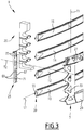
Fig 3 ] lafigure 3 est une vue en perspective éclatée et, partielle, du dispositif d'aération représenté sur lesfigures 1 et2 , le dispositif étant vu depuis le côté amont. - En référence aux
figures 1 à 3 , on décrit un dispositif d'aération 1 selon l'invention. - Le dispositif d'aération 1 est par exemple destiné à faire partie d'une calandre, d'une face avant technique ou d'un pare-chocs d'un véhicule automobile pour admettre un flux d'air F (
figure 2 ) depuis l'extérieur du véhicule automobile vers l'intérieur. - Le dispositif d'aération 1 comprend un cadre 5 définissant une ouverture 7 pour le flux d'air F, une pluralité de volets 10, 12, 14, 16 montés rotatifs sur le cadre respectivement autour d'axes de pivotement L1, L2, L3, L4 entre une position fermée (représentée sur la
figure 1 ), adaptée pour réduire l'intensité du flux d'air F ou modifier sa direction, et une position ouverte (non représentée, mais se déduisant de la position fermée par une rotation des volets autour de leurs axes de pivotement), adaptée pour laisser passer le flux d'air. - Le dispositif d'aération 1 comprend également un support intermédiaire 20 rapporté sur le cadre 5, et s'étendant selon un axe transversal T1, par exemple sensiblement perpendiculaire à l'axe de pivotement L1.
- Avantageusement, le dispositif d'aération comprend en outre une pièce de maintien 25 rapportée sur le cadre 5 pour maintenir les volets 10 à 16 contre le cadre.
- On définit également un axe T2 sensiblement perpendiculaire à l'axe de pivotement L1 et à l'axe transversal T1. L'axe T2 est donc sensiblement perpendiculaire à l'ouverture 7.
- L'axe T2 est par exemple sensiblement parallèle à un axe avant-arrière du véhicule automobile (non représenté).
- L'axe de pivotement L1 est par exemple sensiblement parallèle aux essieux (non représentés) du véhicule automobile.
- L'axe transversal T1 est donc, dans l'exemple représenté, sensiblement vertical.
- Selon une variante non représentée, l'axe T1 forme un certain angle avec la verticale et n'est plus perpendiculaire à l'axe T2.
- Selon un mode de réalisation, dans la position fermée, l'intensité du flux d'air F est sensiblement nulle, c'est-à-dire que la position fermée est une position d'obturation complète.
- Le cadre 5, les volets 10 à 16, le support intermédiaire 20 et l'éventuelle pièce de maintien 25 sont avantageusement réalisés en un matériau polymère par tous moyen industriel adapté, par exemple par injection dans des moules appropriés (non représentés).
- Selon un mode de réalisation particulier, le cadre 5 est formé par une calandre du véhicule automobile.
- Dans l'exemple représenté, l'ouverture 7 est sensiblement rectangulaire.
- Selon des variantes non représentées, l'ouverture 7 peut présenter d'autres formes, notamment oblongues ou elliptiques.
- Le cadre 5 comprend deux portions 27, 29 formant, dans l'exemple représenté, respectivement une poutre supérieure et une poutre inférieure sensiblement parallèles à l'axe de pivotement L1. Le cadre 5 comprend aussi deux portions 31, 33 formant, dans l'exemple représenté, deux montants dont la forme générale est sensiblement parallèle à l'axe transversal T1.
- Les portions 27, 29, 31, 33 délimitent l'ouverture 7.
- Le support intermédiaire 20 est fabriqué séparément du cadre 5 (c'est une pièce distincte du cadre).
- Le support intermédiaire 20 forme par exemple un barreau.
- En variante, des formes plus complexes sont possibles.
- Selon une variante non représentée, le support intermédiaire 20 fait partie d'une autre pièce du véhicule, par exemple une face avant technique.
- Le support intermédiaire relie avantageusement les portions 27, 29 du cadre 5 selon l'axe transversal T1. Le support intermédiaire 20 est par exemple vissé ou encliqueté respectivement sur ces portions.
- Le support intermédiaire 20 comporte avantageusement des protubérances 35 s'étendant respectivement vers les volets 10 à 16 selon l'axe T2 et sur lesquelles les volets sont montés rotatifs respectivement autour des axes de pivotement L1 à L4.
- Le support intermédiaire 20 est situé entre une première extrémité 37 et une deuxième extrémité 39 du volet 10 selon l'axe de pivotement L1. Avantageusement, le support intermédiaire 20 est situé sensiblement à égale distance de ces extrémités selon l'axe de pivotement L1.
- Les volets 10 à 16 forment un système d'obturation de l'ouverture 7.
- Dans l'exemple représenté, les axes de pivotement L1 à L4 sont sensiblement parallèles entre eux, et les volets 10 à 16 sont montés sur les portions 31, 33 du cadre 5, successivement selon l'axe transversal T1, avantageusement de manière régulièrement espacée selon cet axe.
- Les volets 10 à 16 forment avantageusement un écran 41 (
figure 1 ) dans la position fermée, adapté pour masquer le support intermédiaire 20 pour un observateur 43 situé de l'autre côté de l'écran par rapport au support intermédiaire selon l'axe T2. - Avantageusement, les volets 10 à 16 sont structurellement analogues les uns aux autres, et sont fixés sur le cadre 5 et le support intermédiaire 20 de manière analogue. Aussi, seul le volet 10 sera décrit en détail ci-après.
- Le volet 10 comprend par exemple un corps 45 s'étendant depuis la première extrémité 37 jusqu'à la deuxième extrémité 39 selon l'axe de pivotement L1, et une portion de fixation 47 située entre la première extrémité et la deuxième extrémité, avantageusement sensiblement à égale distance des deux.
- Le volet 10 comporte aussi, avantageusement, des attaches 49 en saillie, par exemple situées respectivement au niveau de la première extrémité 37 et de la deuxième extrémité 39, et destinées à permettre d'actionner le volet autour de l'axe de pivotement L1.
- Selon un mode de réalisation particulier, il est envisageable de rendre fixe au moins l'un des volets 10 à 16, afin de permettre l'implantation, par exemple, d'une plaque police ou d'un LIDAR. Ce volet est par exemple rendu fixe par l'ajout d'un point de fixation supplémentaire sur au moins une des extrémités 37 et 39, ou en désalignant ses points de fixation de sorte que la rotation autour de l'axe de pivotement ne soit plus possible. Dans ce cas, le dispositif d'aération 1 comporte par exemple un ou plusieurs volets mobiles (analogues aux volets 10 à 16), et un ou plusieurs volets fixes.
- Le corps 45 forme par exemple un ruban avantageusement arqué autour de l'axe transversal T1 dans la position fermée. Cette forme arquée se traduit par l'existence d'une flèche E du ruban par rapport à l'axe de pivotement L1 selon l'axe T2. Dit autrement, la première extrémité 37 et la deuxième extrémité 39 sont situées au niveau de l'axe de pivotement L1, tandis que le centre du corps 45 est situé à l'écart de l'axe de pivotement L1 d'une distance E selon l'axe T2.
- La première extrémité 37 forme un premier pion 51. Le premier pion 51 est situé dans un premier logement 53 défini par la portion 31 du cadre 5. Le premier pion 51 et le premier logement 53 forment un premier pivot du volet 10 autour de l'axe de pivotement L1. Le premier pion 51 et le premier logement 53 sont configurés pour s'emboîter l'un dans l'autre selon l'axe de pivotement L1 lors d'une étape de montage du dispositif d'aération 1 qui sera décrite plus tard.
- Le premier pion 51 présente par exemple une forme cylindrique axée sur l'axe de pivotement L1.
- Le premier logement 53 est par exemple un simple orifice qui entoure avantageusement complètement le premier pion 51 autour de l'axe de pivotement L1.
- Selon une variante non représentée, la première extrémité 37 du volet 10 forme un logement et la portion 31 du cadre 5 forme un pion de manière à réaliser le premier pivot.
- La deuxième extrémité 39 forme un deuxième pion 55. Le deuxième pion 55 est situé dans un deuxième logement 57 formé en partie par la portion 33 du cadre 5 et par la pièce de maintien 25. Le deuxième pion 55 et le deuxième logement 57 forment un deuxième pivot autour de l'axe de pivotement L1 entre le volet 10 et le cadre 5. Le deuxième logement 57 est configuré pour recevoir le deuxième pion 55 lors d'une étape de montage du dispositif d'aération 1 après que le premier pion 51 a été inséré dans le premier logement 53, le deuxième pion étant reçu selon un axe sensiblement perpendiculaire à l'axe de pivotement L1, par exemple selon l'axe T2. Selon une variante non représentée, la deuxième extrémité 39 forme un logement et le cadre 5 forme un pion reçu dans ledit logement pour former le deuxième pivot.
- Le deuxième logement 57 est par exemple formé par une encoche dans le cadre 5.
- La portion de fixation 47 présente par exemple une forme de cale. La portion de fixation 47 est montée sur le support intermédiaire 20 par exemple de manière à réaliser une liaison pivot stricte autour de l'axe de pivotement L1, avec éventuellement la possibilité d'une légère translation du volet 10 par rapport au support intermédiaire 20 selon l'axe de pivotement L1.
- La portion de fixation 47 forme un troisième pion 59. Le troisième pion 47 est situé dans un troisième logement 61 défini par l'une des protubérances 35 du support intermédiaire 20 de manière à former un troisième pivot autour de l'axe de pivotement L1 entre le volet 10 et le support intermédiaire 20. Le troisième pion 59 et le troisième logement 61 sont configurés pour s'emboîter l'un dans l'autre selon l'axe de pivotement L1 lors d'une étape de montage du volet 10 sur le support intermédiaire 20.
- Le troisième logement 61 est par exemple un orifice entourant avantageusement complètement le troisième pion 59 autour de l'axe de pivotement L1.
- Selon une variante non représentée, la portion de fixation 47 forme un logement et le support intermédiaire 20 forme un pion adapté pour coopérer avec ce logement pour constituer le troisième pivot.
- La portion de fixation 47 forme en outre un quatrième pion 63. Le quatrième pion 63 est situé dans un quatrième logement 65 formé par ladite protubérance 35 du support intermédiaire 20 pour constituer un quatrième pivot autour de l'axe de pivotement L1 entre le volet 10 et le support intermédiaire. Le quatrième pion 63 est par exemple configuré pour s'encliqueter dans le quatrième logement 65 selon un axe sensiblement perpendiculaire à l'axe de pivotement L1, par exemple l'axe T2.
- Selon une variante non représentée, la portion de fixation 47 forme un logement et le support intermédiaire 20 forme un pion situé dans le logement pour constituer le quatrième pivot.
- Du fait que la portion de fixation 47 formant le troisième pion 59 et le quatrième pion 63 est prise entre le troisième logement 61 et le quatrième logement 65, le volet 20 n'est libre en rotation par rapport au support intermédiaire 20 qu'autour de l'axe de pivotement L1.
- Le premier pion 51, le deuxième pion 55, le troisième pion 59 et le quatrième pion 63 sont sensiblement alignés selon l'axe de pivotement L1.
- La pièce de maintien 25 est adaptée pour maintenir le deuxième pion 55 dans le logement 57. La pièce 25 comprend par exemple une partie principale 67 s'étendant selon l'axe transversal T1, et des protubérances 69 dirigées selon l'axe T2 à partir de la partie principale.
- Selon une variante non représentée, le deuxième pion 55 est encliqueté dans le deuxième logement 57, et la pièce de maintien 25 n'est pas utilisée.
- Selon une autre variante non représentée, la pièce de maintien est remplacée par un système à plusieurs pièces, chacune servant à maintenir l'un des volets.
- Chacune des protubérances 69 forme un logement 71 adapté pour être appliqué contre le troisième pion 55 des volets 10 à 16 de manière à pousser ce dernier dans le troisième logement 57.
- La pièce de maintien 25 est par exemple vissée ou encliquetée sur le cadre 5, avantageusement sur la portion 33.
- Un procédé de montage du dispositif d'aération 1 va maintenant être décrit.
- Au départ, les pièces constitutives du dispositif d'aération 1 sont séparées les unes des autres, par exemple comme représenté sur la
figure 2 . - Les volets 10 à 16 sont d'abord montés sur le support intermédiaire 20.
- Pour chacun des volets, la partie de fixation 47 est montée sur l'une des protubérances 35. Pour ce faire, le troisième pion 59 est inséré dans le troisième logement 61 selon l'axe de pivotement L1. Puis, le quatrième pion 63 est encliqueté dans le quatrième logement 65.
- A l'issue de ces opérations, le volet 10 se trouve monté pivotant sur le support intermédiaire 20, grâce aux troisième et quatrième pivots.
- On procède de même pour les autres volets 12, 14, 16, qui prennent ainsi leurs positions relatives par rapport au support intermédiaire 20. Ceci permet de déplacer facilement l'ensemble formé par le support intermédiaire 20 et la pluralité de volets.
- Ensuite, les volets 10 à 16 sont montés sur le cadre 5. Pour chacun des volets, le premier pion 51 est introduit dans le premier logement 53 respectivement selon les axes de pivotement L1, L2, L2, L4.
- Ensuite, le deuxième pion 55 est introduit dans le deuxième logement 57 selon l'axe T2, et ce pour chacun des volets 10 à 16.
- Le support intermédiaire 20 est fixé sur le cadre 5 par vissage ou encliquetage.
- On fixe également la pièce de maintien 25 sur le cadre 5 pour retenir les deuxièmes pions 55 dans les deuxièmes logements 57.
- En fonctionnement, on comprend que les volets 10 à 16 sont solidement maintenus sur le cadre 5 et sur le support intermédiaire 20.
- Au côté de la première extrémité 37, le premier pion 51, après montage, ne peut pas s'écarter du premier logement 53 selon les directions perpendiculaires à l'axe de pivotement L1. Le seul degré de liberté permis pour le volet 10 est une rotation autour de l'axe de pivotement L1 par rapport au cadre 5, et éventuellement une légère translation selon l'axe de pivotement L1.
- De même, le troisième pion 59 pivote dans le troisième logement 61 autour de l'axe de pivotement L1, mais ne peut pas s'écarter de l'axe de pivotement L1 selon les directions perpendiculaires à l'axe de pivotement.
- Enfin, du côté de la deuxième extrémité 39, grâce à la pièce de maintien 25, le deuxième pion 55 pivote dans le deuxième logement 57, mais ne peut pas sortir de ce logement selon les directions perpendiculaires à l'axe de pivotement L1.
- Grâce aux caractéristiques décrites ci-dessus, il est possible de fixer des volets de grande extension selon leur axe de pivotement, typiquement supérieure ou égale à 350 mm voire à 400 mm, sans risque de torsion des volets autour des axes de pivotement, ou plus généralement de déformation des volets qui nuirait au fonctionnement du dispositif d'aération.
- En outre, grâce aux caractéristiques optionnelles selon lesquelles le premier logement 53 et le troisième logement 61 entourent complètement respectivement le premier pion 51 et le troisième pion 59, le volet 10 ne peut pas être déboîté respectivement du cadre 5 et du support intermédiaire 20 par une pression éventuelle d'un utilisateur sur ce volet perpendiculairement à l'axe de pivotement L1. Les volets 10 à 16 sont donc solidement maintenus par le cadre 5 et le support intermédiaire 20.
- Grâce à la pièce de maintien 25 optionnelle, le deuxième pion 55 est également solidement maintenu dans le deuxième logement 57.
- Avantageusement, le support intermédiaire 20 permet de déplacer collectivement la pluralité de volets 10 à 16 pendant le montage. La liaison pivot qui existe de manière avantageuse entre chacun des volets 10 à 16 et le support intermédiaire permet de donner aux volets leur orientation par rapport au support intermédiaire 20.
- En outre, le support intermédiaire 20 est facilement caché par l'écran 41 formé par les volets 10 à 16 dans la position fermée pour l'observateur 43.
- Les principaux avantages du dispositif d'aération 1 sont :
- une démontabilité réduite du système sans outil, c'est-à-dire un gain de sécurité en particulier lorsque les volets 10 à 16 sont visibles,
- un gain de raideur pour les volets 10 à 16 de grande dimension grâce au support intermédiaire 20,
- l'invisibilité du support intermédiaire 20 lorsque les volets sont dans la position fermée,
- un montage facile en usine,
- une robustesse en utilisation du fait de la difficulté à démonter le dispositif, de la raideur des volets et de la fiabilité de l'assemblage,
- une réduction des jeux fonctionnels par rapport à un montage par encliquetage complet,
- une meilleure cohésion entre les volets 10 à 16 et le cadre 5, et
- la possibilité de rendre fixe un ou plusieurs volets afin d'intégrer une plaque de police par exemple.
- En outre, le support intermédiaire 20 peut être fabriqué séparément du cadre 5, ce qui permet de rendre le cadre et le volet éventuellement plus complexes sans dégrader la faisabilité des pièces.
- Le support intermédiaire 20 peut être formé par une autre pièce du véhicule, par exemple une face avant technique ou une pièce de renfort d'un pare-chocs.
- Le support intermédiaire 20 lie avantageusement les portions 27, 29 du cadre 5 et permet un transfert d'éventuels efforts verticaux. En outre, le support intermédiaire 20 peut être dimensionné pour absorber des chocs de type « parking » ou « piéton » ou être fusible.
- L'utilisation d'un support intermédiaire amovible formant un barreau permet de le dimensionner au plus juste sans dégrader sa faisabilité. Il peut comprendre des zones de faiblesse à rupture programmée (zone fusible) pour atteindre des objectifs de raideur prédéfinis.
- L'assemblage des volets à la première extrémité 37 et à la deuxième extrémité 39 est très robuste grâce à des jeux plus aisément contrôlables.
- Grâce au support intermédiaire, les volets sont en outre plus esthétiques lorsqu'ils sont visibles par l'observateur 43.
Claims (10)
- Dispositif d'aération (1) pour un véhicule automobile, le dispositif d'aération (1) comprenant :- un cadre (5) définissant une ouverture (7) pour un flux d'air (F) ayant une intensité et une direction par rapport au cadre (5), et- au moins un volet (10) monté rotatif par rapport au cadre (5) autour d'un axe de pivotement (L1) entre une position ouverte, adaptée pour laisser passer le flux d'air (F), et une position fermée, adaptée pour réduire l'intensité du flux d'air (F) ou modifier sa direction, le volet (10) s'étendant selon l'axe de pivotement (L1) et ayant une première extrémité (37) et une deuxième extrémité (39) opposées selon l'axe de pivotement (L1),caractérisé en ce que :- chacune de la première extrémité (37) et de la deuxième extrémité (39) est montée rotative sur le cadre (5) autour de l'axe de pivotement (L1),- le dispositif d'aération (1) comprend en outre un support intermédiaire (20) situé entre la première extrémité (37) et la deuxième extrémité (39) selon l'axe de pivotement (L1), le volet (10) étant monté rotatif sur le support intermédiaire (20) par rapport au cadre (5) autour de l'axe de pivotement (L1), le support intermédiaire (20) étant rapporté sur le cadre (5).
- Dispositif d'aération (1) selon la revendication 1, dans lequel le support intermédiaire (20) relie deux portions (27, 29) du cadre (5) selon un axe transversal (T1) sensiblement perpendiculaire à l'axe de pivotement (L1), les deux portions (27, 29) étant séparées par l'ouverture (7) selon l'axe transversal (T1), le support intermédiaire (20) étant de préférence vissé ou encliqueté sur chacune de deux portions (27, 29) du cadre (5).
- Dispositif d'aération (1) selon la revendication 1 ou 2, comprenant une pluralité de volets (10, 12, 14, 16) montés rotatifs sur le cadre (5) respectivement autour d'axes de pivotement (L1, L2, L3, L4) entre une position ouverte, adaptée pour laisser passer le flux d'air (F), et une position fermée, adaptée pour réduire l'intensité du flux d'air (F) ou modifier sa direction, les volets (10, 12, 14, 16) formant un écran (41) adapté pour masquer le support intermédiaire (20) pour un observateur (43) situé de l'autre côté de l'écran (41) par rapport au support intermédiaire (20) selon un axe (T2) sensiblement perpendiculaire à l'ouverture (7).
- Dispositif d'aération (1) selon l'une quelconque des revendications 1 à 3, dans lequel :- la première extrémité (37) dudit volet (10) forme l'un d'un premier pion (51) et d'un premier logement (53), et le cadre (5) forme l'autre d'un premier pion (51) et d'un premier logement (53), le premier pion (51) étant situé dans le premier logement (53) pour former un premier pivot autour de l'axe de pivotement (L1) entre le volet (10) et le cadre (5), le premier pion (51) et le premier logement (53) étant configurés pour s'emboîter l'un dans l'autre selon l'axe de pivotement (L1) lors d'une étape de montage du dispositif d'aération (1), et- la deuxième extrémité (39) forme l'un d'un deuxième pion (55) et d'un deuxième logement (57), le cadre (5) formant l'autre d'un deuxième pion (55) et d'un deuxième logement (57), le deuxième pion (55) étant situé dans le deuxième logement (57) pour former au moins en partie un deuxième pivot autour de l'axe de pivotement (L1) entre le volet (10) et le cadre (5).
- Dispositif d'aération (1) selon la revendication 4, dans lequel le premier logement (53) entoure complètement le premier pion (51) autour de l'axe de pivotement (L1).
- Dispositif d'aération (1) selon la revendication 4 ou 5, dans lequel le deuxième logement (57) est configuré pour recevoir le deuxième pion (55) lors d'une étape de montage du dispositif d'aération (1) après que le premier pion (51) a été inséré dans le premier logement (53), le deuxième pion (55) étant reçu dans le deuxième logement (57) selon un axe (T2) sensiblement perpendiculaire à l'axe de pivotement (L1), le dispositif d'aération (1) comprenant de préférence au moins une pièce de maintien (25) rapportée sur le cadre (5) pour maintenir le deuxième pion (55) dans le deuxième logement (57) selon ledit axe (T2).
- Dispositif d'aération (1) selon l'une quelconque des revendications 1 à 5, dans lequel le volet comprend :- un corps (45) s'étendant depuis la première extrémité (37) jusqu'à la deuxième extrémité (39) selon l'axe de pivotement (L1), et- une portion de fixation (47) solidaire du corps (45) et formant l'un troisième pion (59) et d'un troisième logement (61), le support intermédiaire (20) formant l'autre d'un troisième pion (59) et d'un troisième logement (61), le troisième pion (59) étant situé dans le troisième logement (61) pour former un troisième pivot autour de l'axe de pivotement (L1) entre le volet (10) et le support intermédiaire (20), le troisième pion (59) et le troisième logement (61) étant configurés pour s'emboîter l'un dans l'autre selon l'axe de pivotement (L1) lors d'une étape de montage du volet (10) sur le support intermédiaire (20).
- Dispositif d'aération (1) selon la revendication 7, dans lequel le troisième logement (61) entoure complètement le troisième pion (59) autour de l'axe de pivotement (L1).
- Dispositif d'aération (1) selon la revendication 7 ou 8, dans lequel la portion de fixation forme l'un d'un quatrième pion (63) et d'un quatrième logement (65), le support intermédiaire (20) formant l'autre d'un quatrième pion (63) et d'un quatrième logement (65), le quatrième pion (63) étant situé dans le quatrième logement (65) pour former un quatrième pivot autour de l'axe de pivotement (L1) entre le volet (10) et le support intermédiaire (20), le quatrième pion (63) étant configuré pour s'encliqueter dans le quatrième logement (65) selon un axe (T2) sensiblement perpendiculaire à l'axe de pivotement (L1).
- Procédé de montage d'un dispositif d'aération (1) selon l'une quelconque des revendications 1 à 9, comprenant au moins les étapes suivantes :- montage du volet (10) rotatif sur le support intermédiaire (20),- montage de la première extrémité (37) du volet (10) sur le cadre (5),- montage de la deuxième extrémité (39) du volet (10) sur le cadre (5), et- fixation du support intermédiaire (20) sur le cadre (5).
Applications Claiming Priority (1)
| Application Number | Priority Date | Filing Date | Title |
|---|---|---|---|
| FR1903780A FR3094922B1 (fr) | 2019-04-09 | 2019-04-09 | Dispositif d’aération pour véhicule automobile, et procédé de montage |
Publications (2)
| Publication Number | Publication Date |
|---|---|
| EP3722133A1 true EP3722133A1 (fr) | 2020-10-14 |
| EP3722133B1 EP3722133B1 (fr) | 2022-07-27 |
Family
ID=67441433
Family Applications (1)
| Application Number | Title | Priority Date | Filing Date |
|---|---|---|---|
| EP20168730.8A Active EP3722133B1 (fr) | 2019-04-09 | 2020-04-08 | Dispositif d'aération pour véhicule automobile, et procédé de montage |
Country Status (4)
| Country | Link |
|---|---|
| US (1) | US11479110B2 (fr) |
| EP (1) | EP3722133B1 (fr) |
| ES (1) | ES2925269T3 (fr) |
| FR (1) | FR3094922B1 (fr) |
Families Citing this family (3)
| Publication number | Priority date | Publication date | Assignee | Title |
|---|---|---|---|---|
| US11845331B2 (en) | 2022-03-03 | 2023-12-19 | Valeo Systemes Thermiques | Air flow control device for a front face module of a motor vehicle |
| KR20240080986A (ko) * | 2022-11-30 | 2024-06-07 | 현대자동차주식회사 | 가변 그릴 장치 |
| FR3154351A1 (fr) * | 2023-10-20 | 2025-04-25 | Valeo Systemes Thermiques | Dispositif de contrôle d’un flux d’air, ensemble et face avant de véhicule, notamment véhicule automobile, comprenant un tel dispositif |
Citations (7)
| Publication number | Priority date | Publication date | Assignee | Title |
|---|---|---|---|---|
| GB2332657A (en) * | 1997-12-24 | 1999-06-30 | Ecia Equip Composants Ind Auto | Connecting device |
| DE102009058760A1 (de) * | 2009-12-17 | 2011-06-22 | Volkswagen AG, 38440 | Kraftfahrzeug -Lufteinlassvorrichtung, Kühlereinrichtung, Kraftfahrzeug und Verfahren zum Betätigen einer Lufteinlassvorrichtung |
| DE102011004169A1 (de) * | 2011-02-15 | 2012-08-16 | Brose Fahrzeugteile Gmbh & Co. Kommanditgesellschaft, Coburg | Luftklappenanordnung |
| DE102014106605A1 (de) * | 2014-05-12 | 2015-11-12 | Dr. Schneider Kunststoffwerke Gmbh | Rahmen für ein Verschlusssystem |
| US20160236563A1 (en) * | 2012-08-31 | 2016-08-18 | Magna International, Inc. | Active grille multi part modular frame |
| EP3272565A1 (fr) * | 2016-07-20 | 2018-01-24 | Kunststoff Schwanden AG | Rideau de radiateur |
| DE102017105568A1 (de) * | 2017-03-15 | 2018-09-20 | Geiger Automotive Gmbh | Modulares Luftklappensystem |
Family Cites Families (10)
| Publication number | Priority date | Publication date | Assignee | Title |
|---|---|---|---|---|
| US3500739A (en) * | 1968-05-23 | 1970-03-17 | John P Dry | Plastic register with shutter blades |
| FR2938805B1 (fr) * | 2008-11-24 | 2011-09-30 | Faurecia Bloc Avant | Module de face avant de vehicule automobile comprenant un bouclier |
| CA2974627C (fr) * | 2009-07-21 | 2018-12-04 | Magna International Inc. | Support de volet de compartiment de vehicule a conduit integre |
| DE202010013597U1 (de) * | 2010-09-24 | 2010-11-25 | GM Global Technology Operations, Inc., Detroit | Gehäuse für die Kühlerjalousie eines Kraftfahrzeuges |
| CH706456B1 (de) * | 2012-04-30 | 2016-03-15 | Schwanden Kunststoff | Jalousie für die Anordnung vor einem Kühler. |
| US9931926B2 (en) * | 2012-08-31 | 2018-04-03 | Magna Exteriors Inc. | Active grille multi part modular frame |
| US9162641B2 (en) * | 2012-11-12 | 2015-10-20 | GM Global Technology Operations LLC | Front fascia or grill support structure and aerodynamic shutter assembly |
| DE102015109702A1 (de) * | 2015-06-17 | 2016-12-22 | Hbpo Gmbh | Verschlussvorrichtung zum Verschließen eines funktionswesentlichen Bauteils eines Fahrzeuges |
| DE102016007369A1 (de) * | 2016-06-16 | 2017-12-21 | GM Global Technology Operations LLC (n. d. Ges. d. Staates Delaware) | Kühlerjalousie für ein Kraftfahrzeug |
| US10093173B1 (en) * | 2017-07-26 | 2018-10-09 | Srg Global Inc. | Active grille shutter system with louver compensation feature |
-
2019
- 2019-04-09 FR FR1903780A patent/FR3094922B1/fr not_active Expired - Fee Related
-
2020
- 2020-04-08 ES ES20168730T patent/ES2925269T3/es active Active
- 2020-04-08 US US16/843,688 patent/US11479110B2/en active Active
- 2020-04-08 EP EP20168730.8A patent/EP3722133B1/fr active Active
Patent Citations (7)
| Publication number | Priority date | Publication date | Assignee | Title |
|---|---|---|---|---|
| GB2332657A (en) * | 1997-12-24 | 1999-06-30 | Ecia Equip Composants Ind Auto | Connecting device |
| DE102009058760A1 (de) * | 2009-12-17 | 2011-06-22 | Volkswagen AG, 38440 | Kraftfahrzeug -Lufteinlassvorrichtung, Kühlereinrichtung, Kraftfahrzeug und Verfahren zum Betätigen einer Lufteinlassvorrichtung |
| DE102011004169A1 (de) * | 2011-02-15 | 2012-08-16 | Brose Fahrzeugteile Gmbh & Co. Kommanditgesellschaft, Coburg | Luftklappenanordnung |
| US20160236563A1 (en) * | 2012-08-31 | 2016-08-18 | Magna International, Inc. | Active grille multi part modular frame |
| DE102014106605A1 (de) * | 2014-05-12 | 2015-11-12 | Dr. Schneider Kunststoffwerke Gmbh | Rahmen für ein Verschlusssystem |
| EP3272565A1 (fr) * | 2016-07-20 | 2018-01-24 | Kunststoff Schwanden AG | Rideau de radiateur |
| DE102017105568A1 (de) * | 2017-03-15 | 2018-09-20 | Geiger Automotive Gmbh | Modulares Luftklappensystem |
Also Published As
| Publication number | Publication date |
|---|---|
| ES2925269T3 (es) | 2022-10-14 |
| FR3094922B1 (fr) | 2021-06-25 |
| FR3094922A1 (fr) | 2020-10-16 |
| US11479110B2 (en) | 2022-10-25 |
| EP3722133B1 (fr) | 2022-07-27 |
| US20200324642A1 (en) | 2020-10-15 |
Similar Documents
| Publication | Publication Date | Title |
|---|---|---|
| EP3722133B1 (fr) | Dispositif d'aération pour véhicule automobile, et procédé de montage | |
| EP3634800B1 (fr) | Dispositif d'obturation d'entree d'air de vehicule automobile et procede de fabrication d'un tel dispositif d'obturation | |
| EP3944985A1 (fr) | Siege de vehicule | |
| EP3702189A1 (fr) | Dispositif d'aération pour un véhicule | |
| EP3736156B1 (fr) | Dispositif d'aération pour un véhicule, procédé de montage associé | |
| EP3045357B1 (fr) | Capot d essuie-glace configuré pour recouvrir une partie terminale d'un bras d'essuie-glace | |
| EP4313650A1 (fr) | Ensemble de régulation d'un flux d'air pour véhicule automobile | |
| EP3902710B1 (fr) | Adaptateur pour monture de balai d'essuyage de véhicule automobile | |
| EP4613528A2 (fr) | Calandre de radiateur avec volets mobiles et procédé de montage correspondant | |
| EP3924203A1 (fr) | Dispositif d'obturation pour entree d'air de face avant de vehicule automobile comportant un dispositif de desolidarisation de volet | |
| FR3041307A1 (fr) | Organe d’essuie-glace comprenant un capot articule | |
| EP1059415A1 (fr) | Enrouleur de sangle, mécanisme de manoeuvre d'un volet ou store roulant comprenant un tel enrouleur et procédé de fabrication d'un tel enrouleur | |
| EP3725578B1 (fr) | Dispositif d'aération pour un véhicule, véhicule associé | |
| EP3461701B1 (fr) | Dispositif de connexion d'un balai d'essuyage a un bras d'entrainemant pour vehicule | |
| FR3102102A1 (fr) | Dispositif d’obturation pour entrée d’air de face avant de véhicule automobile comportant un dispositif de désolidarisation de volet | |
| EP1853439B1 (fr) | Dispositif anti-dérapage pour véhicule | |
| EP4296760B1 (fr) | Paire de lunettes a pion de verrouillage et procede de montage correspondant | |
| WO2025125758A1 (fr) | Casque de protection muni d'une mentonniere amovible | |
| EP4454921A1 (fr) | Calandre de véhicule automobile à ouverture réglable | |
| WO2024126418A1 (fr) | Adaptateur d'un système d'essuyage | |
| EP4214078A1 (fr) | Cadre pour un dispositif de regulation d'arrivee d'air d'un vehicule | |
| WO2022058186A1 (fr) | Cadre pour un dispositif de regulation d'arrivee d'air d'un vehicule | |
| EP1926852B1 (fr) | Dispositif d'accrochage entre un cadre de lisses et une bielle, cadre de lisses equipe d'un tel dispositif, mecanisme d'actionnement d'un tel cadre et metier a tisser incorporant un tel mecanisme | |
| EP0928871A1 (fr) | Perfectionnement d'articulation d'un ouvrant sur un dormant | |
| EP2786669A1 (fr) | Ecran de protection articulé, interchangeable |
Legal Events
| Date | Code | Title | Description |
|---|---|---|---|
| PUAI | Public reference made under article 153(3) epc to a published international application that has entered the european phase |
Free format text: ORIGINAL CODE: 0009012 |
|
| STAA | Information on the status of an ep patent application or granted ep patent |
Free format text: STATUS: THE APPLICATION HAS BEEN PUBLISHED |
|
| AK | Designated contracting states |
Kind code of ref document: A1 Designated state(s): AL AT BE BG CH CY CZ DE DK EE ES FI FR GB GR HR HU IE IS IT LI LT LU LV MC MK MT NL NO PL PT RO RS SE SI SK SM TR |
|
| AX | Request for extension of the european patent |
Extension state: BA ME |
|
| STAA | Information on the status of an ep patent application or granted ep patent |
Free format text: STATUS: REQUEST FOR EXAMINATION WAS MADE |
|
| 17P | Request for examination filed |
Effective date: 20210322 |
|
| RBV | Designated contracting states (corrected) |
Designated state(s): AL AT BE BG CH CY CZ DE DK EE ES FI FR GB GR HR HU IE IS IT LI LT LU LV MC MK MT NL NO PL PT RO RS SE SI SK SM TR |
|
| GRAP | Despatch of communication of intention to grant a patent |
Free format text: ORIGINAL CODE: EPIDOSNIGR1 |
|
| RIC1 | Information provided on ipc code assigned before grant |
Ipc: F01P 7/10 20060101ALI20211112BHEP Ipc: B60K 11/08 20060101AFI20211112BHEP |
|
| STAA | Information on the status of an ep patent application or granted ep patent |
Free format text: STATUS: GRANT OF PATENT IS INTENDED |
|
| INTG | Intention to grant announced |
Effective date: 20211223 |
|
| GRAJ | Information related to disapproval of communication of intention to grant by the applicant or resumption of examination proceedings by the epo deleted |
Free format text: ORIGINAL CODE: EPIDOSDIGR1 |
|
| STAA | Information on the status of an ep patent application or granted ep patent |
Free format text: STATUS: REQUEST FOR EXAMINATION WAS MADE |
|
| GRAP | Despatch of communication of intention to grant a patent |
Free format text: ORIGINAL CODE: EPIDOSNIGR1 |
|
| STAA | Information on the status of an ep patent application or granted ep patent |
Free format text: STATUS: GRANT OF PATENT IS INTENDED |
|
| INTC | Intention to grant announced (deleted) | ||
| INTG | Intention to grant announced |
Effective date: 20220225 |
|
| GRAS | Grant fee paid |
Free format text: ORIGINAL CODE: EPIDOSNIGR3 |
|
| GRAA | (expected) grant |
Free format text: ORIGINAL CODE: 0009210 |
|
| STAA | Information on the status of an ep patent application or granted ep patent |
Free format text: STATUS: THE PATENT HAS BEEN GRANTED |
|
| AK | Designated contracting states |
Kind code of ref document: B1 Designated state(s): AL AT BE BG CH CY CZ DE DK EE ES FI FR GB GR HR HU IE IS IT LI LT LU LV MC MK MT NL NO PL PT RO RS SE SI SK SM TR |
|
| REG | Reference to a national code |
Ref country code: CH Ref legal event code: EP |
|
| REG | Reference to a national code |
Ref country code: DE Ref legal event code: R096 Ref document number: 602020004148 Country of ref document: DE |
|
| REG | Reference to a national code |
Ref country code: AT Ref legal event code: REF Ref document number: 1506853 Country of ref document: AT Kind code of ref document: T Effective date: 20220815 |
|
| REG | Reference to a national code |
Ref country code: IE Ref legal event code: FG4D Free format text: LANGUAGE OF EP DOCUMENT: FRENCH |
|
| REG | Reference to a national code |
Ref country code: ES Ref legal event code: FG2A Ref document number: 2925269 Country of ref document: ES Kind code of ref document: T3 Effective date: 20221014 |
|
| REG | Reference to a national code |
Ref country code: LT Ref legal event code: MG9D |
|
| REG | Reference to a national code |
Ref country code: NL Ref legal event code: MP Effective date: 20220727 |
|
| PG25 | Lapsed in a contracting state [announced via postgrant information from national office to epo] |
Ref country code: SE Free format text: LAPSE BECAUSE OF FAILURE TO SUBMIT A TRANSLATION OF THE DESCRIPTION OR TO PAY THE FEE WITHIN THE PRESCRIBED TIME-LIMIT Effective date: 20220727 Ref country code: RS Free format text: LAPSE BECAUSE OF FAILURE TO SUBMIT A TRANSLATION OF THE DESCRIPTION OR TO PAY THE FEE WITHIN THE PRESCRIBED TIME-LIMIT Effective date: 20220727 Ref country code: PT Free format text: LAPSE BECAUSE OF FAILURE TO SUBMIT A TRANSLATION OF THE DESCRIPTION OR TO PAY THE FEE WITHIN THE PRESCRIBED TIME-LIMIT Effective date: 20221128 Ref country code: NO Free format text: LAPSE BECAUSE OF FAILURE TO SUBMIT A TRANSLATION OF THE DESCRIPTION OR TO PAY THE FEE WITHIN THE PRESCRIBED TIME-LIMIT Effective date: 20221027 Ref country code: NL Free format text: LAPSE BECAUSE OF FAILURE TO SUBMIT A TRANSLATION OF THE DESCRIPTION OR TO PAY THE FEE WITHIN THE PRESCRIBED TIME-LIMIT Effective date: 20220727 Ref country code: LV Free format text: LAPSE BECAUSE OF FAILURE TO SUBMIT A TRANSLATION OF THE DESCRIPTION OR TO PAY THE FEE WITHIN THE PRESCRIBED TIME-LIMIT Effective date: 20220727 Ref country code: LT Free format text: LAPSE BECAUSE OF FAILURE TO SUBMIT A TRANSLATION OF THE DESCRIPTION OR TO PAY THE FEE WITHIN THE PRESCRIBED TIME-LIMIT Effective date: 20220727 Ref country code: FI Free format text: LAPSE BECAUSE OF FAILURE TO SUBMIT A TRANSLATION OF THE DESCRIPTION OR TO PAY THE FEE WITHIN THE PRESCRIBED TIME-LIMIT Effective date: 20220727 |
|
| REG | Reference to a national code |
Ref country code: AT Ref legal event code: MK05 Ref document number: 1506853 Country of ref document: AT Kind code of ref document: T Effective date: 20220727 |
|
| PG25 | Lapsed in a contracting state [announced via postgrant information from national office to epo] |
Ref country code: PL Free format text: LAPSE BECAUSE OF FAILURE TO SUBMIT A TRANSLATION OF THE DESCRIPTION OR TO PAY THE FEE WITHIN THE PRESCRIBED TIME-LIMIT Effective date: 20220727 Ref country code: IS Free format text: LAPSE BECAUSE OF FAILURE TO SUBMIT A TRANSLATION OF THE DESCRIPTION OR TO PAY THE FEE WITHIN THE PRESCRIBED TIME-LIMIT Effective date: 20221127 Ref country code: HR Free format text: LAPSE BECAUSE OF FAILURE TO SUBMIT A TRANSLATION OF THE DESCRIPTION OR TO PAY THE FEE WITHIN THE PRESCRIBED TIME-LIMIT Effective date: 20220727 Ref country code: GR Free format text: LAPSE BECAUSE OF FAILURE TO SUBMIT A TRANSLATION OF THE DESCRIPTION OR TO PAY THE FEE WITHIN THE PRESCRIBED TIME-LIMIT Effective date: 20221028 |
|
| PG25 | Lapsed in a contracting state [announced via postgrant information from national office to epo] |
Ref country code: SM Free format text: LAPSE BECAUSE OF FAILURE TO SUBMIT A TRANSLATION OF THE DESCRIPTION OR TO PAY THE FEE WITHIN THE PRESCRIBED TIME-LIMIT Effective date: 20220727 Ref country code: RO Free format text: LAPSE BECAUSE OF FAILURE TO SUBMIT A TRANSLATION OF THE DESCRIPTION OR TO PAY THE FEE WITHIN THE PRESCRIBED TIME-LIMIT Effective date: 20220727 Ref country code: DK Free format text: LAPSE BECAUSE OF FAILURE TO SUBMIT A TRANSLATION OF THE DESCRIPTION OR TO PAY THE FEE WITHIN THE PRESCRIBED TIME-LIMIT Effective date: 20220727 Ref country code: CZ Free format text: LAPSE BECAUSE OF FAILURE TO SUBMIT A TRANSLATION OF THE DESCRIPTION OR TO PAY THE FEE WITHIN THE PRESCRIBED TIME-LIMIT Effective date: 20220727 Ref country code: AT Free format text: LAPSE BECAUSE OF FAILURE TO SUBMIT A TRANSLATION OF THE DESCRIPTION OR TO PAY THE FEE WITHIN THE PRESCRIBED TIME-LIMIT Effective date: 20220727 |
|
| REG | Reference to a national code |
Ref country code: DE Ref legal event code: R097 Ref document number: 602020004148 Country of ref document: DE |
|
| PG25 | Lapsed in a contracting state [announced via postgrant information from national office to epo] |
Ref country code: SK Free format text: LAPSE BECAUSE OF FAILURE TO SUBMIT A TRANSLATION OF THE DESCRIPTION OR TO PAY THE FEE WITHIN THE PRESCRIBED TIME-LIMIT Effective date: 20220727 Ref country code: EE Free format text: LAPSE BECAUSE OF FAILURE TO SUBMIT A TRANSLATION OF THE DESCRIPTION OR TO PAY THE FEE WITHIN THE PRESCRIBED TIME-LIMIT Effective date: 20220727 |
|
| PLBE | No opposition filed within time limit |
Free format text: ORIGINAL CODE: 0009261 |
|
| STAA | Information on the status of an ep patent application or granted ep patent |
Free format text: STATUS: NO OPPOSITION FILED WITHIN TIME LIMIT |
|
| PG25 | Lapsed in a contracting state [announced via postgrant information from national office to epo] |
Ref country code: AL Free format text: LAPSE BECAUSE OF FAILURE TO SUBMIT A TRANSLATION OF THE DESCRIPTION OR TO PAY THE FEE WITHIN THE PRESCRIBED TIME-LIMIT Effective date: 20220727 |
|
| 26N | No opposition filed |
Effective date: 20230502 |
|
| PG25 | Lapsed in a contracting state [announced via postgrant information from national office to epo] |
Ref country code: SI Free format text: LAPSE BECAUSE OF FAILURE TO SUBMIT A TRANSLATION OF THE DESCRIPTION OR TO PAY THE FEE WITHIN THE PRESCRIBED TIME-LIMIT Effective date: 20220727 |
|
| REG | Reference to a national code |
Ref country code: CH Ref legal event code: PL |
|
| PG25 | Lapsed in a contracting state [announced via postgrant information from national office to epo] |
Ref country code: LU Free format text: LAPSE BECAUSE OF NON-PAYMENT OF DUE FEES Effective date: 20230408 |
|
| REG | Reference to a national code |
Ref country code: BE Ref legal event code: MM Effective date: 20230430 |
|
| PG25 | Lapsed in a contracting state [announced via postgrant information from national office to epo] |
Ref country code: MC Free format text: LAPSE BECAUSE OF FAILURE TO SUBMIT A TRANSLATION OF THE DESCRIPTION OR TO PAY THE FEE WITHIN THE PRESCRIBED TIME-LIMIT Effective date: 20220727 |
|
| PG25 | Lapsed in a contracting state [announced via postgrant information from national office to epo] |
Ref country code: MC Free format text: LAPSE BECAUSE OF FAILURE TO SUBMIT A TRANSLATION OF THE DESCRIPTION OR TO PAY THE FEE WITHIN THE PRESCRIBED TIME-LIMIT Effective date: 20220727 Ref country code: LI Free format text: LAPSE BECAUSE OF NON-PAYMENT OF DUE FEES Effective date: 20230430 Ref country code: CH Free format text: LAPSE BECAUSE OF NON-PAYMENT OF DUE FEES Effective date: 20230430 |
|
| REG | Reference to a national code |
Ref country code: IE Ref legal event code: MM4A |
|
| PG25 | Lapsed in a contracting state [announced via postgrant information from national office to epo] |
Ref country code: BE Free format text: LAPSE BECAUSE OF NON-PAYMENT OF DUE FEES Effective date: 20230430 |
|
| PG25 | Lapsed in a contracting state [announced via postgrant information from national office to epo] |
Ref country code: IE Free format text: LAPSE BECAUSE OF NON-PAYMENT OF DUE FEES Effective date: 20230408 |
|
| PG25 | Lapsed in a contracting state [announced via postgrant information from national office to epo] |
Ref country code: IE Free format text: LAPSE BECAUSE OF NON-PAYMENT OF DUE FEES Effective date: 20230408 |
|
| PGFP | Annual fee paid to national office [announced via postgrant information from national office to epo] |
Ref country code: IT Payment date: 20240320 Year of fee payment: 5 |
|
| PG25 | Lapsed in a contracting state [announced via postgrant information from national office to epo] |
Ref country code: BG Free format text: LAPSE BECAUSE OF FAILURE TO SUBMIT A TRANSLATION OF THE DESCRIPTION OR TO PAY THE FEE WITHIN THE PRESCRIBED TIME-LIMIT Effective date: 20220727 |
|
| PG25 | Lapsed in a contracting state [announced via postgrant information from national office to epo] |
Ref country code: BG Free format text: LAPSE BECAUSE OF FAILURE TO SUBMIT A TRANSLATION OF THE DESCRIPTION OR TO PAY THE FEE WITHIN THE PRESCRIBED TIME-LIMIT Effective date: 20220727 |
|
| PGFP | Annual fee paid to national office [announced via postgrant information from national office to epo] |
Ref country code: GB Payment date: 20250319 Year of fee payment: 6 |
|
| PGFP | Annual fee paid to national office [announced via postgrant information from national office to epo] |
Ref country code: DE Payment date: 20250319 Year of fee payment: 6 |
|
| PGFP | Annual fee paid to national office [announced via postgrant information from national office to epo] |
Ref country code: ES Payment date: 20250502 Year of fee payment: 6 |
|
| PG25 | Lapsed in a contracting state [announced via postgrant information from national office to epo] |
Ref country code: CY Free format text: LAPSE BECAUSE OF FAILURE TO SUBMIT A TRANSLATION OF THE DESCRIPTION OR TO PAY THE FEE WITHIN THE PRESCRIBED TIME-LIMIT; INVALID AB INITIO Effective date: 20200408 |
|
| PG25 | Lapsed in a contracting state [announced via postgrant information from national office to epo] |
Ref country code: HU Free format text: LAPSE BECAUSE OF FAILURE TO SUBMIT A TRANSLATION OF THE DESCRIPTION OR TO PAY THE FEE WITHIN THE PRESCRIBED TIME-LIMIT; INVALID AB INITIO Effective date: 20200408 |
|
| PG25 | Lapsed in a contracting state [announced via postgrant information from national office to epo] |
Ref country code: TR Free format text: LAPSE BECAUSE OF FAILURE TO SUBMIT A TRANSLATION OF THE DESCRIPTION OR TO PAY THE FEE WITHIN THE PRESCRIBED TIME-LIMIT Effective date: 20220727 |
|
| PG25 | Lapsed in a contracting state [announced via postgrant information from national office to epo] |
Ref country code: IT Free format text: LAPSE BECAUSE OF NON-PAYMENT OF DUE FEES Effective date: 20250408 |
|
| PGFP | Annual fee paid to national office [announced via postgrant information from national office to epo] |
Ref country code: FR Payment date: 20260310 Year of fee payment: 7 |