EP3722129A1 - Vehicle body component, battery pack, and vehicle having battery mounted therein - Google Patents
Vehicle body component, battery pack, and vehicle having battery mounted therein Download PDFInfo
- Publication number
- EP3722129A1 EP3722129A1 EP18886618.0A EP18886618A EP3722129A1 EP 3722129 A1 EP3722129 A1 EP 3722129A1 EP 18886618 A EP18886618 A EP 18886618A EP 3722129 A1 EP3722129 A1 EP 3722129A1
- Authority
- EP
- European Patent Office
- Prior art keywords
- magnetic
- magnets
- vehicle
- battery
- magnetic force
- Prior art date
- Legal status (The legal status is an assumption and is not a legal conclusion. Google has not performed a legal analysis and makes no representation as to the accuracy of the status listed.)
- Granted
Links
Images
Classifications
-
- B—PERFORMING OPERATIONS; TRANSPORTING
- B60—VEHICLES IN GENERAL
- B60L—PROPULSION OF ELECTRICALLY-PROPELLED VEHICLES; SUPPLYING ELECTRIC POWER FOR AUXILIARY EQUIPMENT OF ELECTRICALLY-PROPELLED VEHICLES; ELECTRODYNAMIC BRAKE SYSTEMS FOR VEHICLES IN GENERAL; MAGNETIC SUSPENSION OR LEVITATION FOR VEHICLES; MONITORING OPERATING VARIABLES OF ELECTRICALLY-PROPELLED VEHICLES; ELECTRIC SAFETY DEVICES FOR ELECTRICALLY-PROPELLED VEHICLES
- B60L50/00—Electric propulsion with power supplied within the vehicle
- B60L50/50—Electric propulsion with power supplied within the vehicle using propulsion power supplied by batteries or fuel cells
- B60L50/60—Electric propulsion with power supplied within the vehicle using propulsion power supplied by batteries or fuel cells using power supplied by batteries
- B60L50/64—Constructional details of batteries specially adapted for electric vehicles
-
- B—PERFORMING OPERATIONS; TRANSPORTING
- B60—VEHICLES IN GENERAL
- B60K—ARRANGEMENT OR MOUNTING OF PROPULSION UNITS OR OF TRANSMISSIONS IN VEHICLES; ARRANGEMENT OR MOUNTING OF PLURAL DIVERSE PRIME-MOVERS IN VEHICLES; AUXILIARY DRIVES FOR VEHICLES; INSTRUMENTATION OR DASHBOARDS FOR VEHICLES; ARRANGEMENTS IN CONNECTION WITH COOLING, AIR INTAKE, GAS EXHAUST OR FUEL SUPPLY OF PROPULSION UNITS IN VEHICLES
- B60K1/00—Arrangement or mounting of electrical propulsion units
- B60K1/04—Arrangement or mounting of electrical propulsion units of the electric storage means for propulsion
-
- B—PERFORMING OPERATIONS; TRANSPORTING
- B60—VEHICLES IN GENERAL
- B60L—PROPULSION OF ELECTRICALLY-PROPELLED VEHICLES; SUPPLYING ELECTRIC POWER FOR AUXILIARY EQUIPMENT OF ELECTRICALLY-PROPELLED VEHICLES; ELECTRODYNAMIC BRAKE SYSTEMS FOR VEHICLES IN GENERAL; MAGNETIC SUSPENSION OR LEVITATION FOR VEHICLES; MONITORING OPERATING VARIABLES OF ELECTRICALLY-PROPELLED VEHICLES; ELECTRIC SAFETY DEVICES FOR ELECTRICALLY-PROPELLED VEHICLES
- B60L50/00—Electric propulsion with power supplied within the vehicle
- B60L50/50—Electric propulsion with power supplied within the vehicle using propulsion power supplied by batteries or fuel cells
- B60L50/60—Electric propulsion with power supplied within the vehicle using propulsion power supplied by batteries or fuel cells using power supplied by batteries
- B60L50/66—Arrangements of batteries
-
- B—PERFORMING OPERATIONS; TRANSPORTING
- B60—VEHICLES IN GENERAL
- B60L—PROPULSION OF ELECTRICALLY-PROPELLED VEHICLES; SUPPLYING ELECTRIC POWER FOR AUXILIARY EQUIPMENT OF ELECTRICALLY-PROPELLED VEHICLES; ELECTRODYNAMIC BRAKE SYSTEMS FOR VEHICLES IN GENERAL; MAGNETIC SUSPENSION OR LEVITATION FOR VEHICLES; MONITORING OPERATING VARIABLES OF ELECTRICALLY-PROPELLED VEHICLES; ELECTRIC SAFETY DEVICES FOR ELECTRICALLY-PROPELLED VEHICLES
- B60L53/00—Methods of charging batteries, specially adapted for electric vehicles; Charging stations or on-board charging equipment therefor; Exchange of energy storage elements in electric vehicles
- B60L53/80—Exchanging energy storage elements, e.g. removable batteries
-
- H—ELECTRICITY
- H01—ELECTRIC ELEMENTS
- H01F—MAGNETS; INDUCTANCES; TRANSFORMERS; SELECTION OF MATERIALS FOR THEIR MAGNETIC PROPERTIES
- H01F7/00—Magnets
- H01F7/02—Permanent magnets [PM]
- H01F7/04—Means for releasing the attractive force
-
- H—ELECTRICITY
- H01—ELECTRIC ELEMENTS
- H01M—PROCESSES OR MEANS, e.g. BATTERIES, FOR THE DIRECT CONVERSION OF CHEMICAL ENERGY INTO ELECTRICAL ENERGY
- H01M50/00—Constructional details or processes of manufacture of the non-active parts of electrochemical cells other than fuel cells, e.g. hybrid cells
- H01M50/20—Mountings; Secondary casings or frames; Racks, modules or packs; Suspension devices; Shock absorbers; Transport or carrying devices; Holders
- H01M50/244—Secondary casings; Racks; Suspension devices; Carrying devices; Holders characterised by their mounting method
-
- H—ELECTRICITY
- H01—ELECTRIC ELEMENTS
- H01M—PROCESSES OR MEANS, e.g. BATTERIES, FOR THE DIRECT CONVERSION OF CHEMICAL ENERGY INTO ELECTRICAL ENERGY
- H01M50/00—Constructional details or processes of manufacture of the non-active parts of electrochemical cells other than fuel cells, e.g. hybrid cells
- H01M50/20—Mountings; Secondary casings or frames; Racks, modules or packs; Suspension devices; Shock absorbers; Transport or carrying devices; Holders
- H01M50/249—Mountings; Secondary casings or frames; Racks, modules or packs; Suspension devices; Shock absorbers; Transport or carrying devices; Holders specially adapted for aircraft or vehicles, e.g. cars or trains
-
- B—PERFORMING OPERATIONS; TRANSPORTING
- B60—VEHICLES IN GENERAL
- B60K—ARRANGEMENT OR MOUNTING OF PROPULSION UNITS OR OF TRANSMISSIONS IN VEHICLES; ARRANGEMENT OR MOUNTING OF PLURAL DIVERSE PRIME-MOVERS IN VEHICLES; AUXILIARY DRIVES FOR VEHICLES; INSTRUMENTATION OR DASHBOARDS FOR VEHICLES; ARRANGEMENTS IN CONNECTION WITH COOLING, AIR INTAKE, GAS EXHAUST OR FUEL SUPPLY OF PROPULSION UNITS IN VEHICLES
- B60K1/00—Arrangement or mounting of electrical propulsion units
- B60K1/04—Arrangement or mounting of electrical propulsion units of the electric storage means for propulsion
- B60K2001/0455—Removal or replacement of the energy storages
-
- H—ELECTRICITY
- H01—ELECTRIC ELEMENTS
- H01M—PROCESSES OR MEANS, e.g. BATTERIES, FOR THE DIRECT CONVERSION OF CHEMICAL ENERGY INTO ELECTRICAL ENERGY
- H01M2220/00—Batteries for particular applications
- H01M2220/20—Batteries in motive systems, e.g. vehicle, ship, plane
-
- Y—GENERAL TAGGING OF NEW TECHNOLOGICAL DEVELOPMENTS; GENERAL TAGGING OF CROSS-SECTIONAL TECHNOLOGIES SPANNING OVER SEVERAL SECTIONS OF THE IPC; TECHNICAL SUBJECTS COVERED BY FORMER USPC CROSS-REFERENCE ART COLLECTIONS [XRACs] AND DIGESTS
- Y02—TECHNOLOGIES OR APPLICATIONS FOR MITIGATION OR ADAPTATION AGAINST CLIMATE CHANGE
- Y02E—REDUCTION OF GREENHOUSE GAS [GHG] EMISSIONS, RELATED TO ENERGY GENERATION, TRANSMISSION OR DISTRIBUTION
- Y02E60/00—Enabling technologies; Technologies with a potential or indirect contribution to GHG emissions mitigation
- Y02E60/10—Energy storage using batteries
-
- Y—GENERAL TAGGING OF NEW TECHNOLOGICAL DEVELOPMENTS; GENERAL TAGGING OF CROSS-SECTIONAL TECHNOLOGIES SPANNING OVER SEVERAL SECTIONS OF THE IPC; TECHNICAL SUBJECTS COVERED BY FORMER USPC CROSS-REFERENCE ART COLLECTIONS [XRACs] AND DIGESTS
- Y02—TECHNOLOGIES OR APPLICATIONS FOR MITIGATION OR ADAPTATION AGAINST CLIMATE CHANGE
- Y02T—CLIMATE CHANGE MITIGATION TECHNOLOGIES RELATED TO TRANSPORTATION
- Y02T10/00—Road transport of goods or passengers
- Y02T10/60—Other road transportation technologies with climate change mitigation effect
- Y02T10/70—Energy storage systems for electromobility, e.g. batteries
-
- Y—GENERAL TAGGING OF NEW TECHNOLOGICAL DEVELOPMENTS; GENERAL TAGGING OF CROSS-SECTIONAL TECHNOLOGIES SPANNING OVER SEVERAL SECTIONS OF THE IPC; TECHNICAL SUBJECTS COVERED BY FORMER USPC CROSS-REFERENCE ART COLLECTIONS [XRACs] AND DIGESTS
- Y02—TECHNOLOGIES OR APPLICATIONS FOR MITIGATION OR ADAPTATION AGAINST CLIMATE CHANGE
- Y02T—CLIMATE CHANGE MITIGATION TECHNOLOGIES RELATED TO TRANSPORTATION
- Y02T10/00—Road transport of goods or passengers
- Y02T10/60—Other road transportation technologies with climate change mitigation effect
- Y02T10/7072—Electromobility specific charging systems or methods for batteries, ultracapacitors, supercapacitors or double-layer capacitors
Definitions
- the invention relates to a battery, and in particular to a quickly swappable battery.
- a battery In existing electric vehicles, a battery is mounted on a whole vehicle through multiple bolts. When the battery is mounted or detached, it is necessary to mount or detach the multiple bolts. Not only is the workload heavy, but when the battery is in an emergency condition, the whole vehicle cannot be quickly separated from the battery, which is likely to cause danger to the vehicle and a person therein.
- An objective of the invention is to overcome problems of existing battery mounting devices, and to provide a vehicle body component, a battery pack, and a vehicle having a battery mounted therein.
- the technical problem to be solved is to improve the existing problem of the battery being not easy to mount and detach, such that the battery is more conveniently and rapidly mounted and detached. When the battery has a fault, it can be quickly detached, thereby protecting the vehicle and a person therein against danger.
- the vehicle body component proposed according to the invention comprises a magnetic force device, which is switchable between a magnetic state and a non-magnetic state and is able to attract a magnetic object in the magnetic state.
- the foregoing vehicle body component comprises a magnetic force device, which is switchable between a magnetic state and a non-magnetic state and is able to attract a magnetic object in the magnetic state.
- the magnetic force device comprises two groups of magnets, the magnitudes of the magnetic forces of the two groups of magnets are the same, the two groups of magnets are placed side by side, and one group of magnets is rotatable by 180°.
- each of the magnets is a permanent magnet.
- each of the magnets is a Nd 2 -Fe-14B permanent magnet.
- the rotatable magnet is driven by an electric motor, and the electric motor is disposed on the vehicle body component.
- the electric motor is a magnetic force control electric motor.
- the magnetic force device is provided with a mounting and positioning groove matching a positioning protrusion on a battery pack.
- the battery pack proposed according to the invention is provided with a magnetic object.
- the magnetic object is a mounting block fixed to the battery pack.
- the mounting block is provided with a positioning protrusion which matches a mounting and positioning groove on the magnetic force device.
- the foregoing vehicle body component further comprises a magnetic force device, which is switchable between a magnetic state and a non-magnetic state and is able to attract a magnetic object on the battery pack in the magnetic state.
- the vehicle having a battery mounted therein comprises a magnetic force device, which is switchable between a magnetic state and a non-magnetic state and is able to attract a battery pack in the magnetic state.
- the foregoing vehicle having a battery mounted therein comprises a battery pack provided with a magnetic object.
- the magnetic force device comprises two groups of magnets, the magnitudes of the magnetic forces of the two groups of magnets are the same, the two groups of magnets are placed side by side, and one group of magnets is rotatable by 180°.
- each of the magnets is a permanent magnet.
- each of the magnets is a Nd 2 -Fe-14B permanent magnet.
- the rotatable magnet is driven by an electric motor, and the electric motor is disposed on the vehicle body component.
- the electric motor is a magnetic force control electric motor.
- the magnetic object is a mounting block fixed to the battery pack.
- a mounting and positioning device is disposed between the magnetic force device and the magnetic object.
- the mounting and positioning device comprises a mounting and positioning groove disposed on the magnetic force device and a positioning protrusion disposed on the mounting block, the positioning protrusion being placed in the mounting and positioning groove.
- a non-magnetizer is wrapped around each of the two groups of magnets.
- the invention has at least the following advantages and beneficial effects:
- a battery pack of the invention is not limited to being applied to a vehicle, but can be applied to any apparatus that needs to have a battery mounted therein.
- a vehicle having a battery mounted therein comprises a battery pack 10 provided with a magnetic object, and a magnetic force device 20, which is fixed to a vehicle body component, specifically a right body longitudinal rail, and may also be fixed to any component where the battery is to be installed.
- the magnetic force device 20 has two states. In a first state, the magnetic force device has magnetism and can attract the magnetic object such that the battery pack 10 is relatively fixed in position to the vehicle body component. In a second state, the magnetic force device has no magnetism and has no attraction force to the magnetic object, and the battery pack 10 can be separated from the vehicle body component.
- the magnetic force device 20 comprises two groups of magnets 21, 22, the magnitudes of the magnetic forces of the two groups of magnets 21, 22 are the same, the two groups of magnets 21, 22 are placed side by side, and one group of magnets is rotatable by 180°.
- Fig. 2 when magnetic poles of upper and lower magnets are in the same direction, the magnetic force device 20 is in a loaded state, has magnetism, and can attract the magnetic object. If one group of magnets rotates by 180°, referring to Fig. 3 , the magnetic poles of the upper and lower magnets have opposite directions, the magnetic force device 20 is in an unloaded state, the magnetism disappears, and there is no attraction force between the magnetic force device and the magnetic object.
- each of the two groups of magnets 21, 22 is a single sufficiently large magnet, and the magnetic forces of the two magnets are the same.
- the two groups of magnets 21, 22 are formed by a plurality of magnets, the magnetic forces of the two groups of magnets are the same, the two groups of magnets 21, 22 are Nd 2 -Fe-14B permanent magnets, the rotatable magnets are driven by an electric motor 24, and the electric motor 24 is mounted to the right body longitudinal rail.
- the electric motor 24 is a magnetic force control electric motor, i.e.
- the purpose of using the magnetic force control electric motor is to use the rotational motion of a motor shaft to control and achieve the presence or absence of the magnetic force of the magnetic force device, which is similar to a switching action.
- the electric motor 24 uses another ordinary electric motor.
- the Nd 2 -Fe-14B permanent magnet has strong magnetism and light weight, and the attraction force of the whole magnetic force device 20 reaches 400 kgf, which makes the battery pack 10 firmly fixed to the vehicle body component, and reduces the weight of the whole vehicle.
- the magnetic object is a mounting block 11 welded and fixed to the battery pack 10, and the mounting block 11 is made of a ferromagnetic material.
- the mounting block 11 is made of another magnetic material, and the magnetic force device 20 fixes the battery pack 10 by means of attracting the mounting block 11.
- the magnetic object is a magnetic component on a shell of the battery pack 10.
- a mounting and positioning device is disposed between the magnetic force device 20 and the magnetic object.
- the mounting and positioning device comprises a mounting and positioning groove disposed on the magnetic force device 20, and a positioning protrusion 12 disposed on the mounting block 11.
- the positioning protrusion 12 matches the mounting and positioning groove, and the positioning protrusion 12 is placed in the mounting and positioning groove.
- the positioning protrusion 12 needs to be placed in the mounting and positioning groove, which is convenient and rapid and can also prevent misaligmnent between the battery pack 10 and the magnetic force device 20.
- a non-magnetizer 23 is wrapped around each of the two groups of magnets 21, 22.
- the magnetic force device 20 when the battery is mounted, the magnetic force device 20 has a magnetic state, and attracts the magnetic object on the battery pack 10 such that the battery pack 10 is relatively fixed in position to the vehicle body component, and when the battery needs to be detached, the electric motor is used to drive one group of magnets to rotate by 180°, the magnetism of the magnetic force device 20 disappears, and the battery pack can be detached.
- the vehicle body component of the invention comprises a magnetic force device 20.
- the magnetic force device 20 is fixed to the right body longitudinal rail.
- the magnetic force device 20 has two states. In a first state, the magnetic force device has sufficient magnetism and can attract a magnetic object. In a second state, the magnetic force device has no magnetism and has no attraction force to the magnetic object.
- the magnetic force device 20 comprises two groups of magnets 21, 22, the magnitudes of the magnetic forces of the two groups of magnets 21, 22 are the same, the two groups of magnets 21, 22 are placed side by side, and one group of magnets is rotatable by 180°.
- Fig. 2 when magnetic poles of upper and lower magnets are in the same direction, the magnetic force device 20 is in a loaded state, has magnetism, and can attract the magnetic object. If one group of magnets rotates by 180°, referring to Fig. 3 , the magnetic poles of the upper and lower magnets have opposite directions, the magnetic force device 20 is in an unloaded state, the magnetism disappears, and there is no attraction force between the magnetic force device and the magnetic object.
- each of the two groups of magnets 21, 22 is a single sufficiently large magnet, and the magnetic forces of the two magnets are the same.
- the two groups of magnets 21, 22 are formed by a plurality of magnets, the magnetic forces of the two groups of magnets are the same, and the two groups of magnets 21, 22 are Nd 2 -Fe-14B permanent magnets.
- the rotatable magnets are driven by an electric motor 24, the electric motor 24 is mounted to the right body longitudinal rail, and the electric motor 24 is a magnetic force control electric motor.
- the electric motor 24 uses another ordinary electric motor.
- the Nd 2 -Fe-14B permanent magnet has strong magnetism and light weight, and the attraction force of the whole magnetic force device 20 reaches 400 kgf, which can firmly attract the battery pack, and reduces the weight of the whole vehicle.
- a mounting and positioning device is disposed between the magnetic force device 20 and the magnetic object.
- the mounting and positioning device comprises a mounting and positioning groove disposed on the magnetic force device 20, and a positioning protrusion 12 disposed on the mounting block 11.
- the positioning protrusion 12 matches the mounting and positioning groove, and the positioning protrusion 12 is placed in the mounting and positioning groove.
- the positioning protrusion 12 needs to be placed in the mounting and positioning groove, which is convenient and rapid and can also prevent misalignment between the battery pack 10 and the magnetic force device 20.
- a non-magnetizer 23 is wrapped around each of the two groups of magnets 21, 22.
- a battery pack 10 of the invention is provided with a magnetic object, which is a mounting block 11 welded and fixed to the battery pack 10, and the mounting block 11 is made of a ferromagnetic material.
- the mounting block 11 is made of another magnetic material, and the magnetic force device 20 fixes the battery pack 10 by means of attracting the mounting block 11.
- the magnetic object is a magnetic component on a shell of the battery pack 10.
- the mounting block 11 is provided with a positioning protrusion 12 which matches a mounting and positioning groove on a magnetic force device 20.
- the magnetic force device 20 which is switchable between a magnetic state and a non-magnetic state and is able to attract a magnetic object on the battery pack 10 in the magnetic state.
- the magnetic force device 20 is mounted to the vehicle body or another component and can fix the battery pack.
Landscapes
- Engineering & Computer Science (AREA)
- Chemical & Material Sciences (AREA)
- Transportation (AREA)
- Mechanical Engineering (AREA)
- Power Engineering (AREA)
- Electrochemistry (AREA)
- Chemical Kinetics & Catalysis (AREA)
- General Chemical & Material Sciences (AREA)
- Sustainable Energy (AREA)
- Sustainable Development (AREA)
- Life Sciences & Earth Sciences (AREA)
- Aviation & Aerospace Engineering (AREA)
- Combustion & Propulsion (AREA)
- Physics & Mathematics (AREA)
- Electromagnetism (AREA)
- Battery Mounting, Suspending (AREA)
- Arrangement Or Mounting Of Propulsion Units For Vehicles (AREA)
Abstract
Description
- The invention relates to a battery, and in particular to a quickly swappable battery.
- In existing electric vehicles, a battery is mounted on a whole vehicle through multiple bolts. When the battery is mounted or detached, it is necessary to mount or detach the multiple bolts. Not only is the workload heavy, but when the battery is in an emergency condition, the whole vehicle cannot be quickly separated from the battery, which is likely to cause danger to the vehicle and a person therein.
- An objective of the invention is to overcome problems of existing battery mounting devices, and to provide a vehicle body component, a battery pack, and a vehicle having a battery mounted therein. The technical problem to be solved is to improve the existing problem of the battery being not easy to mount and detach, such that the battery is more conveniently and rapidly mounted and detached. When the battery has a fault, it can be quickly detached, thereby protecting the vehicle and a person therein against danger.
- The following technical solutions are used to achieve the objective of the invention and address the technical problem to be solved. The vehicle body component proposed according to the invention comprises a magnetic force device, which is switchable between a magnetic state and a non-magnetic state and is able to attract a magnetic object in the magnetic state.
- The following technical measures may also be used to further achieve the objective of the invention and solve the technical problem of the invention.
- The foregoing vehicle body component comprises a magnetic force device, which is switchable between a magnetic state and a non-magnetic state and is able to attract a magnetic object in the magnetic state.
- In the foregoing vehicle body component, the magnetic force device comprises two groups of magnets, the magnitudes of the magnetic forces of the two groups of magnets are the same, the two groups of magnets are placed side by side, and one group of magnets is rotatable by 180°.
- In the foregoing vehicle body component, each of the magnets is a permanent magnet.
- In the foregoing vehicle body component, each of the magnets is a Nd2-Fe-14B permanent magnet.
- In the foregoing vehicle body component, the rotatable magnet is driven by an electric motor, and the electric motor is disposed on the vehicle body component.
- In the foregoing vehicle body component, the electric motor is a magnetic force control electric motor.
- In the foregoing vehicle body component, the magnetic force device is provided with a mounting and positioning groove matching a positioning protrusion on a battery pack.
- The battery pack proposed according to the invention is provided with a magnetic object.
- In the foregoing vehicle body component, the magnetic object is a mounting block fixed to the battery pack.
- In the foregoing vehicle body component, the mounting block is provided with a positioning protrusion which matches a mounting and positioning groove on the magnetic force device.
- The foregoing vehicle body component further comprises a magnetic force device, which is switchable between a magnetic state and a non-magnetic state and is able to attract a magnetic object on the battery pack in the magnetic state.
- The vehicle having a battery mounted therein, proposed according to the invention, comprises a magnetic force device, which is switchable between a magnetic state and a non-magnetic state and is able to attract a battery pack in the magnetic state.
- The foregoing vehicle having a battery mounted therein comprises a battery pack provided with a magnetic object.
- In the foregoing vehicle having a battery mounted therein, the magnetic force device comprises two groups of magnets, the magnitudes of the magnetic forces of the two groups of magnets are the same, the two groups of magnets are placed side by side, and one group of magnets is rotatable by 180°.
- In the foregoing vehicle having a battery mounted therein, each of the magnets is a permanent magnet.
- In the foregoing vehicle having a battery mounted therein, each of the magnets is a Nd2-Fe-14B permanent magnet.
- In the foregoing vehicle having a battery mounted therein, the rotatable magnet is driven by an electric motor, and the electric motor is disposed on the vehicle body component.
- In the foregoing vehicle having a battery mounted therein, the electric motor is a magnetic force control electric motor.
- In the foregoing vehicle having a battery mounted therein, the magnetic object is a mounting block fixed to the battery pack.
- In the foregoing vehicle having a battery mounted therein, a mounting and positioning device is disposed between the magnetic force device and the magnetic object.
- In the foregoing vehicle having a battery mounted therein, the mounting and positioning device comprises a mounting and positioning groove disposed on the magnetic force device and a positioning protrusion disposed on the mounting block, the positioning protrusion being placed in the mounting and positioning groove.
- In the foregoing vehicle having a battery mounted therein, a non-magnetizer is wrapped around each of the two groups of magnets.
- By virtue of the above technical solutions, the invention has at least the following advantages and beneficial effects:
- (1) the vehicle body component of the invention comprises a magnetic force device, which is switchable between a magnetic state and a non-magnetic state and is able to attract a magnetic object in the magnetic state, thus when a battery pack is mounted to a vehicle body, an attraction force of the magnetic force device can be used to fix the battery pack, and the battery pack can be easily detached in the non-magnetic state, which requires no detachment of bolts and achieves rapid and convenient installation;
- (2) the battery pack of the invention is provided with a magnetic object, and during installation, the magnetic object can be attracted on the battery pack, which is convenient and rapid;
- (3) the vehicle having a battery mounted therein according to the invention comprises a battery pack provided with a magnetic object, and a magnetic force device, and the magnetic force device can attract the magnetic object in the magnetic state to fix the battery pack, and can easily detach the battery pack in the non-magnetic state, which requires no detachment of bolts and achieves rapid and convenient installation;
- (4) in the vehicle having a battery mounted therein according to the invention, the magnets used in the magnetic force device are Nd2-Fe-14B permanent magnets, which have strong magnetism and light weight, making the battery pack firmly mounted and reducing the weight of the whole vehicle; and
- (5) in the vehicle having a battery mounted therein according to the invention, a mounting and positioning device is disposed between the magnetic force device and a ferromagnetic object, and during installation, only a positioning protrusion needs to be placed in the mounting and positioning groove, which is convenient and rapid and can also prevent misalignment between the battery pack and the magnetic force device.
- The aforementioned description is only an overview of the technical solutions of the invention. In order to clearly understand the technical means of the invention, the invention can be implemented according to the contents of the description; and in order to make the aforementioned and other objects, features and advantages of the invention more obvious and understandable, preferred embodiments are described in detail below with reference to the accompanying drawings.
-
-
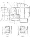
Fig. 1 is a structural schematic diagram of a vehicle having a battery mounted therein according to the invention. -
Fig. 2 is a first schematic diagram of a magnetic force device in the vehicle having a battery mounted therein according to the invention. -
Fig. 3 is a second schematic diagram of the magnetic force device in the vehicle having a battery mounted therein according to the invention. -
10: Battery pack 20: Magnetic force device 11: Mounting block 21: Magnet 12: Positioning protrusion 22: Magnet 30: Right body longitudinal rail 23: Non-magnetizer 24: Electric motor - In order to further illustrate the technical means used to achieve the intended purpose of the invention and the technical effects of the invention, the implementation of a device for quick swap of a vehicle battery proposed in the invention and the features and effects thereof are described in detail hereinafter in conjunction with the accompanying drawings and the preferred embodiments.
- A battery pack of the invention is not limited to being applied to a vehicle, but can be applied to any apparatus that needs to have a battery mounted therein.
- Referring to
Fig. 1 , a vehicle having a battery mounted therein according to the invention comprises a battery pack 10 provided with a magnetic object, and amagnetic force device 20, which is fixed to a vehicle body component, specifically a right body longitudinal rail, and may also be fixed to any component where the battery is to be installed. Themagnetic force device 20 has two states. In a first state, the magnetic force device has magnetism and can attract the magnetic object such that the battery pack 10 is relatively fixed in position to the vehicle body component. In a second state, the magnetic force device has no magnetism and has no attraction force to the magnetic object, and the battery pack 10 can be separated from the vehicle body component. - In an embodiment, the
magnetic force device 20 comprises two groups of magnets 21, 22, the magnitudes of the magnetic forces of the two groups of magnets 21, 22 are the same, the two groups of magnets 21, 22 are placed side by side, and one group of magnets is rotatable by 180°. Referring toFig. 2 , when magnetic poles of upper and lower magnets are in the same direction, themagnetic force device 20 is in a loaded state, has magnetism, and can attract the magnetic object. If one group of magnets rotates by 180°, referring toFig. 3 , the magnetic poles of the upper and lower magnets have opposite directions, themagnetic force device 20 is in an unloaded state, the magnetism disappears, and there is no attraction force between the magnetic force device and the magnetic object. Specifically, each of the two groups of magnets 21, 22 is a single sufficiently large magnet, and the magnetic forces of the two magnets are the same. As an alternative, the two groups of magnets 21, 22 are formed by a plurality of magnets, the magnetic forces of the two groups of magnets are the same, the two groups of magnets 21, 22 are Nd2-Fe-14B permanent magnets, the rotatable magnets are driven by anelectric motor 24, and theelectric motor 24 is mounted to the right body longitudinal rail. Theelectric motor 24 is a magnetic force control electric motor, i.e. an ordinary DC electric motor, the purpose of using the magnetic force control electric motor is to use the rotational motion of a motor shaft to control and achieve the presence or absence of the magnetic force of the magnetic force device, which is similar to a switching action. As an alternative, theelectric motor 24 uses another ordinary electric motor. The Nd2-Fe-14B permanent magnet has strong magnetism and light weight, and the attraction force of the wholemagnetic force device 20 reaches 400 kgf, which makes the battery pack 10 firmly fixed to the vehicle body component, and reduces the weight of the whole vehicle. - In an embodiment, the magnetic object is a mounting block 11 welded and fixed to the battery pack 10, and the mounting block 11 is made of a ferromagnetic material. As an alternative, the mounting block 11 is made of another magnetic material, and the
magnetic force device 20 fixes the battery pack 10 by means of attracting the mounting block 11. As an alternative, the magnetic object is a magnetic component on a shell of the battery pack 10. - In an embodiment, a mounting and positioning device is disposed between the
magnetic force device 20 and the magnetic object. Specifically, the mounting and positioning device comprises a mounting and positioning groove disposed on themagnetic force device 20, and a positioning protrusion 12 disposed on the mounting block 11. The positioning protrusion 12 matches the mounting and positioning groove, and the positioning protrusion 12 is placed in the mounting and positioning groove. When the battery pack is mounted, only the positioning protrusion 12 needs to be placed in the mounting and positioning groove, which is convenient and rapid and can also prevent misaligmnent between the battery pack 10 and themagnetic force device 20. - In an embodiment, a non-magnetizer 23 is wrapped around each of the two groups of magnets 21, 22.
- In the vehicle having a battery mounted therein according to the invention, when the battery is mounted, the
magnetic force device 20 has a magnetic state, and attracts the magnetic object on the battery pack 10 such that the battery pack 10 is relatively fixed in position to the vehicle body component, and when the battery needs to be detached, the electric motor is used to drive one group of magnets to rotate by 180°, the magnetism of themagnetic force device 20 disappears, and the battery pack can be detached. - Referring to
Fig. 1 , the vehicle body component of the invention comprises amagnetic force device 20. Specifically, themagnetic force device 20 is fixed to the right body longitudinal rail. Themagnetic force device 20 has two states. In a first state, the magnetic force device has sufficient magnetism and can attract a magnetic object. In a second state, the magnetic force device has no magnetism and has no attraction force to the magnetic object. - In an embodiment, the
magnetic force device 20 comprises two groups of magnets 21, 22, the magnitudes of the magnetic forces of the two groups of magnets 21, 22 are the same, the two groups of magnets 21, 22 are placed side by side, and one group of magnets is rotatable by 180°. Referring toFig. 2 , when magnetic poles of upper and lower magnets are in the same direction, themagnetic force device 20 is in a loaded state, has magnetism, and can attract the magnetic object. If one group of magnets rotates by 180°, referring toFig. 3 , the magnetic poles of the upper and lower magnets have opposite directions, themagnetic force device 20 is in an unloaded state, the magnetism disappears, and there is no attraction force between the magnetic force device and the magnetic object. Specifically, each of the two groups of magnets 21, 22 is a single sufficiently large magnet, and the magnetic forces of the two magnets are the same. As an alternative, the two groups of magnets 21, 22 are formed by a plurality of magnets, the magnetic forces of the two groups of magnets are the same, and the two groups of magnets 21, 22 are Nd2-Fe-14B permanent magnets. The rotatable magnets are driven by anelectric motor 24, theelectric motor 24 is mounted to the right body longitudinal rail, and theelectric motor 24 is a magnetic force control electric motor. As an alternative, theelectric motor 24 uses another ordinary electric motor. The Nd2-Fe-14B permanent magnet has strong magnetism and light weight, and the attraction force of the wholemagnetic force device 20 reaches 400 kgf, which can firmly attract the battery pack, and reduces the weight of the whole vehicle. - In an embodiment, a mounting and positioning device is disposed between the
magnetic force device 20 and the magnetic object. Specifically, the mounting and positioning device comprises a mounting and positioning groove disposed on themagnetic force device 20, and a positioning protrusion 12 disposed on the mounting block 11. The positioning protrusion 12 matches the mounting and positioning groove, and the positioning protrusion 12 is placed in the mounting and positioning groove. When the battery pack is mounted, only the positioning protrusion 12 needs to be placed in the mounting and positioning groove, which is convenient and rapid and can also prevent misalignment between the battery pack 10 and themagnetic force device 20. - In an embodiment, a non-magnetizer 23 is wrapped around each of the two groups of magnets 21, 22.
- Referring to
Fig. 1 , a battery pack 10 of the invention is provided with a magnetic object, which is a mounting block 11 welded and fixed to the battery pack 10, and the mounting block 11 is made of a ferromagnetic material. As an alternative, the mounting block 11 is made of another magnetic material, and themagnetic force device 20 fixes the battery pack 10 by means of attracting the mounting block 11. As an alternative, the magnetic object is a magnetic component on a shell of the battery pack 10. - In an embodiment, the mounting block 11 is provided with a positioning protrusion 12 which matches a mounting and positioning groove on a
magnetic force device 20. - In an embodiment, also comprised is the
magnetic force device 20, which is switchable between a magnetic state and a non-magnetic state and is able to attract a magnetic object on the battery pack 10 in the magnetic state. Themagnetic force device 20 is mounted to the vehicle body or another component and can fix the battery pack. - The foregoing descriptions are merely preferred embodiments of the invention, and are not intended to limit the invention in any form. Although the invention has been disclosed as above by means of the preferred embodiments, these embodiments are not for the purpose of limiting the invention. Those skilled in the art can make alterations or modifications to the technical contents disclosed above without departing from the technical solutions of the invention so as to arrive at equivalent embodiments with equivalent changes. However, any simple amendments, equivalent changes and modifications made to the above embodiments according to the technical essence of the invention without departing from the technical solutions of the invention are still within the scope of the technical solutions of the invention.
Claims (20)
- A vehicle body component, characterized by comprising
a magnetic force device (20), the magnetic force device (20) being switchable between a magnetic state and a non-magnetic state, and being able to attract a magnetic object in the magnetic state. - The vehicle body component according to claim 1, characterized in that the magnetic force device (20) comprises two groups of magnets (21, 22), the magnitudes of the magnetic forces of the two groups of magnets (21, 22) are the same, the two groups of magnets (21, 22) are placed side by side, and one group of magnets is rotatable by 180°.
- The vehicle body component according to claim 2, characterized in that each of the magnets (21, 22) is a permanent magnet.
- The vehicle body component according to claim 3, characterized in that each of the magnets (21, 22) is a Nd2-Fe-14B permanent magnet.
- The vehicle body component according to claim 2, characterized in that the rotatable magnet is driven by an electric motor (24), which is disposed on the vehicle body component.
- The vehicle body component according to claim 1, characterized in that the magnetic force device (20) is provided with a mounting and positioning groove matching a positioning protrusion on a battery pack.
- A battery pack (10), characterized in that the battery pack (10) is provided with a magnetic object.
- The battery pack according to claim 7, characterized in that the magnetic object is a mounting block (11) fixed to the battery pack (10).
- The battery pack according to claim 8, characterized in that the mounting block (11) is provided with a positioning protrusion (12) which matches a mounting and positioning groove on a magnetic force device (20).
- The battery pack according to claim 7, characterized by further comprising
a magnetic force device (20), which is switchable between a magnetic state and a non-magnetic state, and is able to attract the magnetic object on the battery pack (10) in the magnetic state. - A vehicle having a battery mounted therein, characterized by comprising a magnetic force device (20), the magnetic force device (20) being switchable between a magnetic state and a non-magnetic state, and being able to attract a battery pack in the magnetic state.
- The vehicle having a battery mounted therein according to claim 11, characterized by comprising a battery pack (10), the battery pack (10) being provided with a magnetic object.
- The vehicle having a battery mounted therein according to claim 11, characterized in that
the magnetic force device (20) comprises two groups of magnets (21, 22), the magnitudes of the magnetic forces of the two groups of magnets (21, 22) are the same, the two groups of magnets (21, 22) are placed side by side, and one group of magnets is rotatable by 180°. - The vehicle having a battery mounted therein according to claim 13, characterized in that
each of the magnets (21, 22) is a permanent magnet. - The vehicle having a battery mounted therein according to claim 13, characterized in that each of the magnets (21, 22) is a Nd2-Fe-14B permanent magnet.
- The vehicle having a battery mounted therein according to claim 13, characterized in that the rotatable magnet is driven by an electric motor (24), and the electric motor (24) is disposed on a vehicle body component.
- The vehicle having a battery mounted therein according to claim 12, characterized in that the magnetic object is a mounting block (11) fixed to the battery pack (10).
- The vehicle having a battery mounted therein according to claim 12, characterized in that a mounting and positioning device is disposed between the magnetic force device (20) and the magnetic object.
- The vehicle having a battery mounted therein according to claim 18, characterized in that the mounting and positioning device comprises a mounting and positioning groove disposed on the magnetic force device (20), and a positioning protrusion (12) disposed on the mounting block (11), the positioning protrusion (12) being placed in the mounting and positioning groove.
- The vehicle having a battery mounted therein according to claim 13, characterized in that a non-magnetizer (23) is wrapped around each of the two groups of magnets (21, 22).
Applications Claiming Priority (2)
| Application Number | Priority Date | Filing Date | Title |
|---|---|---|---|
| CN201711278452.6A CN109878315A (en) | 2017-12-06 | 2017-12-06 | Vehicle body components, battery pack and the vehicle for being equipped with battery |
| PCT/CN2018/119352 WO2019109946A1 (en) | 2017-12-06 | 2018-12-05 | Vehicle body component, battery pack, and vehicle having battery mounted therein |
Publications (3)
| Publication Number | Publication Date |
|---|---|
| EP3722129A1 true EP3722129A1 (en) | 2020-10-14 |
| EP3722129A4 EP3722129A4 (en) | 2021-07-21 |
| EP3722129B1 EP3722129B1 (en) | 2023-06-07 |
Family
ID=66751313
Family Applications (1)
| Application Number | Title | Priority Date | Filing Date |
|---|---|---|---|
| EP18886618.0A Active EP3722129B1 (en) | 2017-12-06 | 2018-12-05 | Vehicle comprising a battery pack |
Country Status (3)
| Country | Link |
|---|---|
| EP (1) | EP3722129B1 (en) |
| CN (1) | CN109878315A (en) |
| WO (1) | WO2019109946A1 (en) |
Cited By (1)
| Publication number | Priority date | Publication date | Assignee | Title |
|---|---|---|---|---|
| EP3738917A4 (en) * | 2018-01-09 | 2021-10-06 | NIO (Anhui) Holding Co., Ltd. | Electrically-controlled magnetic connecting device and electric vehicle battery-swapping apparatus |
Families Citing this family (4)
| Publication number | Priority date | Publication date | Assignee | Title |
|---|---|---|---|---|
| JP7334665B2 (en) * | 2020-04-08 | 2023-08-29 | トヨタ自動車株式会社 | Vehicle mounting structure |
| CN113665404B (en) * | 2020-05-15 | 2024-12-06 | 奥动新能源汽车科技有限公司 | Battery bin positioning system and battery bin positioning method |
| CN115431736A (en) * | 2022-09-29 | 2022-12-06 | 安徽江淮汽车集团股份有限公司 | Intelligence quick change battery package structure and electric automobile |
| CN115431738A (en) * | 2022-11-08 | 2022-12-06 | 中国第一汽车股份有限公司 | Electromagnetic control quick-change power battery assembly, electric vehicle and quick-change method |
Family Cites Families (10)
| Publication number | Priority date | Publication date | Assignee | Title |
|---|---|---|---|---|
| CN101476850A (en) * | 2008-12-01 | 2009-07-08 | 上汽通用五菱汽车股份有限公司 | Method for detecting car body component matching degree and car body component thereof |
| DE102009035463A1 (en) * | 2009-07-31 | 2011-02-03 | Daimler Ag | Battery with a large number of plate-shaped battery cells |
| CN203529700U (en) * | 2013-10-12 | 2014-04-09 | 杨国锋 | Novel magnetic crane device |
| CN205335025U (en) * | 2016-01-25 | 2016-06-22 | 深圳市康凯斯信息技术有限公司 | Magnetic means and have its position terminal |
| CN106553514B (en) * | 2016-08-30 | 2018-09-21 | 杭州衡源汽车科技有限公司 | Postposition vibration isolation type pure electric vehicle logistic car Battery pack installation structure |
| US9643656B1 (en) * | 2016-09-07 | 2017-05-09 | David R. Hall | Vehicle energy storage system |
| CN206306812U (en) * | 2016-11-02 | 2017-07-07 | 郭敏 | A kind of drawer type of batteries of electric automobile is installed and changes structure |
| CN106601934A (en) * | 2016-12-12 | 2017-04-26 | 芜湖市吉安汽车电子销售有限公司 | Safety protective apparatus for combined battery pack used for new energy automobile |
| CN206647703U (en) * | 2017-04-18 | 2017-11-17 | 深圳Tcl新技术有限公司 | Display device |
| CN207535678U (en) * | 2017-12-06 | 2018-06-26 | 蔚来汽车有限公司 | Vehicle body parts, battery packs and vehicles with batteries installed |
-
2017
- 2017-12-06 CN CN201711278452.6A patent/CN109878315A/en active Pending
-
2018
- 2018-12-05 WO PCT/CN2018/119352 patent/WO2019109946A1/en not_active Ceased
- 2018-12-05 EP EP18886618.0A patent/EP3722129B1/en active Active
Cited By (1)
| Publication number | Priority date | Publication date | Assignee | Title |
|---|---|---|---|---|
| EP3738917A4 (en) * | 2018-01-09 | 2021-10-06 | NIO (Anhui) Holding Co., Ltd. | Electrically-controlled magnetic connecting device and electric vehicle battery-swapping apparatus |
Also Published As
| Publication number | Publication date |
|---|---|
| WO2019109946A1 (en) | 2019-06-13 |
| EP3722129A4 (en) | 2021-07-21 |
| EP3722129B1 (en) | 2023-06-07 |
| CN109878315A (en) | 2019-06-14 |
Similar Documents
| Publication | Publication Date | Title |
|---|---|---|
| EP3722129A1 (en) | Vehicle body component, battery pack, and vehicle having battery mounted therein | |
| KR102313077B1 (en) | Electromagnet Switchable Permanent Magnet Device | |
| US10596797B2 (en) | Film and device for tearing film | |
| WO2008105041A1 (en) | Magnetic fixing device | |
| KR20180024445A (en) | Contactless driving module and transfer apparatus having the same | |
| ES2138768T3 (en) | ACTIVE SWING ABSORBER. | |
| AU2012275503A1 (en) | Drive system for a transportation system | |
| KR101449736B1 (en) | Bypass apparatus for converter | |
| CN111661559A (en) | Magnetic belt conveyor with automatically controlled permanent magnet | |
| WO2015174582A1 (en) | Sphere magnetic levitation system and method of operating sphere magnetic levitation system | |
| CN201331994Y (en) | Installation component for permanent magnet | |
| CN105523157B (en) | A kind of underwater robot, which is thrown, carries module | |
| US9906088B2 (en) | Rotor-holding structure of rotating electrical machine for hybrid vehicle | |
| WO2017054740A1 (en) | Fixing system for vehicle-mounted electronic device and vehicle having the same | |
| CN207535678U (en) | Vehicle body parts, battery packs and vehicles with batteries installed | |
| JP3173839U (en) | Work reversing device | |
| CN105916789A (en) | Spool fixation device with bi-stable magnet assemblies | |
| CN208026944U (en) | Put mirror low-angle switching mechanism | |
| CN203944465U (en) | Electricity magneto tramp iron separator | |
| KR20230121493A (en) | A magnetic energy system and a transport system using the same | |
| CN107434207B (en) | An electronically controlled permanent magnet chuck with automatic unloading | |
| CN206738392U (en) | A kind of permanent magnet expulsive force type radial direction magnetic bearing | |
| CN108995692B (en) | Sucker device for multiplexing robot | |
| CN218170441U (en) | Manipulator electric permanent magnetic chuck | |
| CN223032382U (en) | Magnetic levitation transportation device |
Legal Events
| Date | Code | Title | Description |
|---|---|---|---|
| STAA | Information on the status of an ep patent application or granted ep patent |
Free format text: STATUS: THE INTERNATIONAL PUBLICATION HAS BEEN MADE |
|
| PUAI | Public reference made under article 153(3) epc to a published international application that has entered the european phase |
Free format text: ORIGINAL CODE: 0009012 |
|
| STAA | Information on the status of an ep patent application or granted ep patent |
Free format text: STATUS: REQUEST FOR EXAMINATION WAS MADE |
|
| 17P | Request for examination filed |
Effective date: 20200706 |
|
| AK | Designated contracting states |
Kind code of ref document: A1 Designated state(s): AL AT BE BG CH CY CZ DE DK EE ES FI FR GB GR HR HU IE IS IT LI LT LU LV MC MK MT NL NO PL PT RO RS SE SI SK SM TR |
|
| AX | Request for extension of the european patent |
Extension state: BA ME |
|
| RAP1 | Party data changed (applicant data changed or rights of an application transferred) |
Owner name: NIO (ANHUI) HOLDING CO., LTD. |
|
| DAV | Request for validation of the european patent (deleted) | ||
| DAX | Request for extension of the european patent (deleted) | ||
| A4 | Supplementary search report drawn up and despatched |
Effective date: 20210622 |
|
| RIC1 | Information provided on ipc code assigned before grant |
Ipc: B60K 1/04 20190101AFI20210616BHEP Ipc: H01F 7/02 20060101ALI20210616BHEP Ipc: B60L 53/80 20190101ALI20210616BHEP Ipc: B66C 1/04 20060101ALI20210616BHEP Ipc: B66C 1/06 20060101ALI20210616BHEP Ipc: H01M 50/20 20210101ALI20210616BHEP |
|
| STAA | Information on the status of an ep patent application or granted ep patent |
Free format text: STATUS: EXAMINATION IS IN PROGRESS |
|
| 17Q | First examination report despatched |
Effective date: 20220510 |
|
| GRAP | Despatch of communication of intention to grant a patent |
Free format text: ORIGINAL CODE: EPIDOSNIGR1 |
|
| STAA | Information on the status of an ep patent application or granted ep patent |
Free format text: STATUS: GRANT OF PATENT IS INTENDED |
|
| RIC1 | Information provided on ipc code assigned before grant |
Ipc: H01M 50/249 20210101ALN20221118BHEP Ipc: H01M 50/244 20210101ALN20221118BHEP Ipc: H01F 7/04 20060101ALN20221118BHEP Ipc: B60L 50/60 20190101ALN20221118BHEP Ipc: B60L 50/64 20190101ALN20221118BHEP Ipc: H01M 50/20 20210101ALN20221118BHEP Ipc: B66C 1/06 20060101ALN20221118BHEP Ipc: B66C 1/04 20060101ALN20221118BHEP Ipc: B60L 53/80 20190101ALN20221118BHEP Ipc: H01F 7/02 20060101ALN20221118BHEP Ipc: B60K 1/04 20190101AFI20221118BHEP |
|
| INTG | Intention to grant announced |
Effective date: 20221222 |
|
| GRAS | Grant fee paid |
Free format text: ORIGINAL CODE: EPIDOSNIGR3 |
|
| GRAA | (expected) grant |
Free format text: ORIGINAL CODE: 0009210 |
|
| STAA | Information on the status of an ep patent application or granted ep patent |
Free format text: STATUS: THE PATENT HAS BEEN GRANTED |
|
| AK | Designated contracting states |
Kind code of ref document: B1 Designated state(s): AL AT BE BG CH CY CZ DE DK EE ES FI FR GB GR HR HU IE IS IT LI LT LU LV MC MK MT NL NO PL PT RO RS SE SI SK SM TR |
|
| REG | Reference to a national code |
Ref country code: GB Ref legal event code: FG4D |
|
| REG | Reference to a national code |
Ref country code: CH Ref legal event code: EP Ref country code: AT Ref legal event code: REF Ref document number: 1573985 Country of ref document: AT Kind code of ref document: T Effective date: 20230615 |
|
| REG | Reference to a national code |
Ref country code: DE Ref legal event code: R096 Ref document number: 602018051616 Country of ref document: DE |
|
| REG | Reference to a national code |
Ref country code: LT Ref legal event code: MG9D |
|
| REG | Reference to a national code |
Ref country code: NL Ref legal event code: MP Effective date: 20230607 |
|
| PG25 | Lapsed in a contracting state [announced via postgrant information from national office to epo] |
Ref country code: SE Free format text: LAPSE BECAUSE OF FAILURE TO SUBMIT A TRANSLATION OF THE DESCRIPTION OR TO PAY THE FEE WITHIN THE PRESCRIBED TIME-LIMIT Effective date: 20230607 Ref country code: NO Free format text: LAPSE BECAUSE OF FAILURE TO SUBMIT A TRANSLATION OF THE DESCRIPTION OR TO PAY THE FEE WITHIN THE PRESCRIBED TIME-LIMIT Effective date: 20230907 Ref country code: ES Free format text: LAPSE BECAUSE OF FAILURE TO SUBMIT A TRANSLATION OF THE DESCRIPTION OR TO PAY THE FEE WITHIN THE PRESCRIBED TIME-LIMIT Effective date: 20230607 |
|
| REG | Reference to a national code |
Ref country code: AT Ref legal event code: MK05 Ref document number: 1573985 Country of ref document: AT Kind code of ref document: T Effective date: 20230607 |
|
| PG25 | Lapsed in a contracting state [announced via postgrant information from national office to epo] |
Ref country code: RS Free format text: LAPSE BECAUSE OF FAILURE TO SUBMIT A TRANSLATION OF THE DESCRIPTION OR TO PAY THE FEE WITHIN THE PRESCRIBED TIME-LIMIT Effective date: 20230607 Ref country code: NL Free format text: LAPSE BECAUSE OF FAILURE TO SUBMIT A TRANSLATION OF THE DESCRIPTION OR TO PAY THE FEE WITHIN THE PRESCRIBED TIME-LIMIT Effective date: 20230607 Ref country code: LV Free format text: LAPSE BECAUSE OF FAILURE TO SUBMIT A TRANSLATION OF THE DESCRIPTION OR TO PAY THE FEE WITHIN THE PRESCRIBED TIME-LIMIT Effective date: 20230607 Ref country code: LT Free format text: LAPSE BECAUSE OF FAILURE TO SUBMIT A TRANSLATION OF THE DESCRIPTION OR TO PAY THE FEE WITHIN THE PRESCRIBED TIME-LIMIT Effective date: 20230607 Ref country code: HR Free format text: LAPSE BECAUSE OF FAILURE TO SUBMIT A TRANSLATION OF THE DESCRIPTION OR TO PAY THE FEE WITHIN THE PRESCRIBED TIME-LIMIT Effective date: 20230607 Ref country code: GR Free format text: LAPSE BECAUSE OF FAILURE TO SUBMIT A TRANSLATION OF THE DESCRIPTION OR TO PAY THE FEE WITHIN THE PRESCRIBED TIME-LIMIT Effective date: 20230908 |
|
| PG25 | Lapsed in a contracting state [announced via postgrant information from national office to epo] |
Ref country code: FI Free format text: LAPSE BECAUSE OF FAILURE TO SUBMIT A TRANSLATION OF THE DESCRIPTION OR TO PAY THE FEE WITHIN THE PRESCRIBED TIME-LIMIT Effective date: 20230607 |
|
| PG25 | Lapsed in a contracting state [announced via postgrant information from national office to epo] |
Ref country code: SK Free format text: LAPSE BECAUSE OF FAILURE TO SUBMIT A TRANSLATION OF THE DESCRIPTION OR TO PAY THE FEE WITHIN THE PRESCRIBED TIME-LIMIT Effective date: 20230607 |
|
| PG25 | Lapsed in a contracting state [announced via postgrant information from national office to epo] |
Ref country code: IS Free format text: LAPSE BECAUSE OF FAILURE TO SUBMIT A TRANSLATION OF THE DESCRIPTION OR TO PAY THE FEE WITHIN THE PRESCRIBED TIME-LIMIT Effective date: 20231007 |
|
| PG25 | Lapsed in a contracting state [announced via postgrant information from national office to epo] |
Ref country code: SM Free format text: LAPSE BECAUSE OF FAILURE TO SUBMIT A TRANSLATION OF THE DESCRIPTION OR TO PAY THE FEE WITHIN THE PRESCRIBED TIME-LIMIT Effective date: 20230607 Ref country code: SK Free format text: LAPSE BECAUSE OF FAILURE TO SUBMIT A TRANSLATION OF THE DESCRIPTION OR TO PAY THE FEE WITHIN THE PRESCRIBED TIME-LIMIT Effective date: 20230607 Ref country code: RO Free format text: LAPSE BECAUSE OF FAILURE TO SUBMIT A TRANSLATION OF THE DESCRIPTION OR TO PAY THE FEE WITHIN THE PRESCRIBED TIME-LIMIT Effective date: 20230607 Ref country code: PT Free format text: LAPSE BECAUSE OF FAILURE TO SUBMIT A TRANSLATION OF THE DESCRIPTION OR TO PAY THE FEE WITHIN THE PRESCRIBED TIME-LIMIT Effective date: 20231009 Ref country code: IS Free format text: LAPSE BECAUSE OF FAILURE TO SUBMIT A TRANSLATION OF THE DESCRIPTION OR TO PAY THE FEE WITHIN THE PRESCRIBED TIME-LIMIT Effective date: 20231007 Ref country code: EE Free format text: LAPSE BECAUSE OF FAILURE TO SUBMIT A TRANSLATION OF THE DESCRIPTION OR TO PAY THE FEE WITHIN THE PRESCRIBED TIME-LIMIT Effective date: 20230607 Ref country code: CZ Free format text: LAPSE BECAUSE OF FAILURE TO SUBMIT A TRANSLATION OF THE DESCRIPTION OR TO PAY THE FEE WITHIN THE PRESCRIBED TIME-LIMIT Effective date: 20230607 Ref country code: AT Free format text: LAPSE BECAUSE OF FAILURE TO SUBMIT A TRANSLATION OF THE DESCRIPTION OR TO PAY THE FEE WITHIN THE PRESCRIBED TIME-LIMIT Effective date: 20230607 |
|
| PG25 | Lapsed in a contracting state [announced via postgrant information from national office to epo] |
Ref country code: PL Free format text: LAPSE BECAUSE OF FAILURE TO SUBMIT A TRANSLATION OF THE DESCRIPTION OR TO PAY THE FEE WITHIN THE PRESCRIBED TIME-LIMIT Effective date: 20230607 |
|
| REG | Reference to a national code |
Ref country code: DE Ref legal event code: R097 Ref document number: 602018051616 Country of ref document: DE |
|
| PLBE | No opposition filed within time limit |
Free format text: ORIGINAL CODE: 0009261 |
|
| STAA | Information on the status of an ep patent application or granted ep patent |
Free format text: STATUS: NO OPPOSITION FILED WITHIN TIME LIMIT |
|
| PG25 | Lapsed in a contracting state [announced via postgrant information from national office to epo] |
Ref country code: DK Free format text: LAPSE BECAUSE OF FAILURE TO SUBMIT A TRANSLATION OF THE DESCRIPTION OR TO PAY THE FEE WITHIN THE PRESCRIBED TIME-LIMIT Effective date: 20230607 |
|
| PG25 | Lapsed in a contracting state [announced via postgrant information from national office to epo] |
Ref country code: SI Free format text: LAPSE BECAUSE OF FAILURE TO SUBMIT A TRANSLATION OF THE DESCRIPTION OR TO PAY THE FEE WITHIN THE PRESCRIBED TIME-LIMIT Effective date: 20230607 |
|
| 26N | No opposition filed |
Effective date: 20240308 |
|
| PG25 | Lapsed in a contracting state [announced via postgrant information from national office to epo] |
Ref country code: SI Free format text: LAPSE BECAUSE OF FAILURE TO SUBMIT A TRANSLATION OF THE DESCRIPTION OR TO PAY THE FEE WITHIN THE PRESCRIBED TIME-LIMIT Effective date: 20230607 Ref country code: IT Free format text: LAPSE BECAUSE OF FAILURE TO SUBMIT A TRANSLATION OF THE DESCRIPTION OR TO PAY THE FEE WITHIN THE PRESCRIBED TIME-LIMIT Effective date: 20230607 |
|
| REG | Reference to a national code |
Ref country code: CH Ref legal event code: PL |
|
| PG25 | Lapsed in a contracting state [announced via postgrant information from national office to epo] |
Ref country code: LU Free format text: LAPSE BECAUSE OF NON-PAYMENT OF DUE FEES Effective date: 20231205 |
|
| PG25 | Lapsed in a contracting state [announced via postgrant information from national office to epo] |
Ref country code: MC Free format text: LAPSE BECAUSE OF FAILURE TO SUBMIT A TRANSLATION OF THE DESCRIPTION OR TO PAY THE FEE WITHIN THE PRESCRIBED TIME-LIMIT Effective date: 20230607 |
|
| REG | Reference to a national code |
Ref country code: BE Ref legal event code: MM Effective date: 20231231 |
|
| PG25 | Lapsed in a contracting state [announced via postgrant information from national office to epo] |
Ref country code: MC Free format text: LAPSE BECAUSE OF FAILURE TO SUBMIT A TRANSLATION OF THE DESCRIPTION OR TO PAY THE FEE WITHIN THE PRESCRIBED TIME-LIMIT Effective date: 20230607 Ref country code: LU Free format text: LAPSE BECAUSE OF NON-PAYMENT OF DUE FEES Effective date: 20231205 |
|
| REG | Reference to a national code |
Ref country code: IE Ref legal event code: MM4A |
|
| PG25 | Lapsed in a contracting state [announced via postgrant information from national office to epo] |
Ref country code: IE Free format text: LAPSE BECAUSE OF NON-PAYMENT OF DUE FEES Effective date: 20231205 |
|
| PG25 | Lapsed in a contracting state [announced via postgrant information from national office to epo] |
Ref country code: BE Free format text: LAPSE BECAUSE OF NON-PAYMENT OF DUE FEES Effective date: 20231231 |
|
| PG25 | Lapsed in a contracting state [announced via postgrant information from national office to epo] |
Ref country code: CH Free format text: LAPSE BECAUSE OF NON-PAYMENT OF DUE FEES Effective date: 20231231 |
|
| PG25 | Lapsed in a contracting state [announced via postgrant information from national office to epo] |
Ref country code: IE Free format text: LAPSE BECAUSE OF NON-PAYMENT OF DUE FEES Effective date: 20231205 Ref country code: CH Free format text: LAPSE BECAUSE OF NON-PAYMENT OF DUE FEES Effective date: 20231231 Ref country code: BE Free format text: LAPSE BECAUSE OF NON-PAYMENT OF DUE FEES Effective date: 20231231 |
|
| PG25 | Lapsed in a contracting state [announced via postgrant information from national office to epo] |
Ref country code: BG Free format text: LAPSE BECAUSE OF FAILURE TO SUBMIT A TRANSLATION OF THE DESCRIPTION OR TO PAY THE FEE WITHIN THE PRESCRIBED TIME-LIMIT Effective date: 20230607 |
|
| PG25 | Lapsed in a contracting state [announced via postgrant information from national office to epo] |
Ref country code: BG Free format text: LAPSE BECAUSE OF FAILURE TO SUBMIT A TRANSLATION OF THE DESCRIPTION OR TO PAY THE FEE WITHIN THE PRESCRIBED TIME-LIMIT Effective date: 20230607 |
|
| PG25 | Lapsed in a contracting state [announced via postgrant information from national office to epo] |
Ref country code: CY Free format text: LAPSE BECAUSE OF FAILURE TO SUBMIT A TRANSLATION OF THE DESCRIPTION OR TO PAY THE FEE WITHIN THE PRESCRIBED TIME-LIMIT; INVALID AB INITIO Effective date: 20181205 |
|
| PG25 | Lapsed in a contracting state [announced via postgrant information from national office to epo] |
Ref country code: HU Free format text: LAPSE BECAUSE OF FAILURE TO SUBMIT A TRANSLATION OF THE DESCRIPTION OR TO PAY THE FEE WITHIN THE PRESCRIBED TIME-LIMIT; INVALID AB INITIO Effective date: 20181205 |
|
| PG25 | Lapsed in a contracting state [announced via postgrant information from national office to epo] |
Ref country code: TR Free format text: LAPSE BECAUSE OF FAILURE TO SUBMIT A TRANSLATION OF THE DESCRIPTION OR TO PAY THE FEE WITHIN THE PRESCRIBED TIME-LIMIT Effective date: 20230607 |
|
| PGFP | Annual fee paid to national office [announced via postgrant information from national office to epo] |
Ref country code: DE Payment date: 20251211 Year of fee payment: 8 |
|
| PGFP | Annual fee paid to national office [announced via postgrant information from national office to epo] |
Ref country code: GB Payment date: 20251219 Year of fee payment: 8 |
|
| PGFP | Annual fee paid to national office [announced via postgrant information from national office to epo] |
Ref country code: FR Payment date: 20251229 Year of fee payment: 8 |