EP3722061B2 - Verwendung eines kontinuierlichen faserbündels in verfahren zur herstellung von faserverstärktem harzformmaterial - Google Patents
Verwendung eines kontinuierlichen faserbündels in verfahren zur herstellung von faserverstärktem harzformmaterial Download PDFInfo
- Publication number
- EP3722061B2 EP3722061B2 EP20178020.2A EP20178020A EP3722061B2 EP 3722061 B2 EP3722061 B2 EP 3722061B2 EP 20178020 A EP20178020 A EP 20178020A EP 3722061 B2 EP3722061 B2 EP 3722061B2
- Authority
- EP
- European Patent Office
- Prior art keywords
- fiber bundle
- fiber
- fiber bundles
- sheet
- separated
- Prior art date
- Legal status (The legal status is an assumption and is not a legal conclusion. Google has not performed a legal analysis and makes no representation as to the accuracy of the status listed.)
- Active
Links
Images


Classifications
-
- B—PERFORMING OPERATIONS; TRANSPORTING
- B29—WORKING OF PLASTICS; WORKING OF SUBSTANCES IN A PLASTIC STATE IN GENERAL
- B29C—SHAPING OR JOINING OF PLASTICS; SHAPING OF MATERIAL IN A PLASTIC STATE, NOT OTHERWISE PROVIDED FOR; AFTER-TREATMENT OF THE SHAPED PRODUCTS, e.g. REPAIRING
- B29C70/00—Shaping composites, i.e. plastics material comprising reinforcements, fillers or preformed parts, e.g. inserts
- B29C70/04—Shaping composites, i.e. plastics material comprising reinforcements, fillers or preformed parts, e.g. inserts comprising reinforcements only, e.g. self-reinforcing plastics
- B29C70/06—Fibrous reinforcements only
- B29C70/10—Fibrous reinforcements only characterised by the structure of fibrous reinforcements, e.g. hollow fibres
-
- B—PERFORMING OPERATIONS; TRANSPORTING
- B29—WORKING OF PLASTICS; WORKING OF SUBSTANCES IN A PLASTIC STATE IN GENERAL
- B29B—PREPARATION OR PRETREATMENT OF THE MATERIAL TO BE SHAPED; MAKING GRANULES OR PREFORMS; RECOVERY OF PLASTICS OR OTHER CONSTITUENTS OF WASTE MATERIAL CONTAINING PLASTICS
- B29B15/00—Pretreatment of the material to be shaped, not covered by groups B29B7/00 - B29B13/00
- B29B15/08—Pretreatment of the material to be shaped, not covered by groups B29B7/00 - B29B13/00 of reinforcements or fillers
- B29B15/10—Coating or impregnating independently of the moulding or shaping step
- B29B15/12—Coating or impregnating independently of the moulding or shaping step of reinforcements of indefinite length
- B29B15/122—Coating or impregnating independently of the moulding or shaping step of reinforcements of indefinite length with a matrix in liquid form, e.g. as melt, solution or latex
- B29B15/125—Coating or impregnating independently of the moulding or shaping step of reinforcements of indefinite length with a matrix in liquid form, e.g. as melt, solution or latex by dipping
-
- B—PERFORMING OPERATIONS; TRANSPORTING
- B29—WORKING OF PLASTICS; WORKING OF SUBSTANCES IN A PLASTIC STATE IN GENERAL
- B29B—PREPARATION OR PRETREATMENT OF THE MATERIAL TO BE SHAPED; MAKING GRANULES OR PREFORMS; RECOVERY OF PLASTICS OR OTHER CONSTITUENTS OF WASTE MATERIAL CONTAINING PLASTICS
- B29B11/00—Making preforms
- B29B11/02—Making preforms by dividing preformed material, e.g. sheets, rods
-
- B—PERFORMING OPERATIONS; TRANSPORTING
- B29—WORKING OF PLASTICS; WORKING OF SUBSTANCES IN A PLASTIC STATE IN GENERAL
- B29B—PREPARATION OR PRETREATMENT OF THE MATERIAL TO BE SHAPED; MAKING GRANULES OR PREFORMS; RECOVERY OF PLASTICS OR OTHER CONSTITUENTS OF WASTE MATERIAL CONTAINING PLASTICS
- B29B15/00—Pretreatment of the material to be shaped, not covered by groups B29B7/00 - B29B13/00
- B29B15/08—Pretreatment of the material to be shaped, not covered by groups B29B7/00 - B29B13/00 of reinforcements or fillers
- B29B15/10—Coating or impregnating independently of the moulding or shaping step
- B29B15/12—Coating or impregnating independently of the moulding or shaping step of reinforcements of indefinite length
- B29B15/122—Coating or impregnating independently of the moulding or shaping step of reinforcements of indefinite length with a matrix in liquid form, e.g. as melt, solution or latex
-
- B—PERFORMING OPERATIONS; TRANSPORTING
- B29—WORKING OF PLASTICS; WORKING OF SUBSTANCES IN A PLASTIC STATE IN GENERAL
- B29B—PREPARATION OR PRETREATMENT OF THE MATERIAL TO BE SHAPED; MAKING GRANULES OR PREFORMS; RECOVERY OF PLASTICS OR OTHER CONSTITUENTS OF WASTE MATERIAL CONTAINING PLASTICS
- B29B15/00—Pretreatment of the material to be shaped, not covered by groups B29B7/00 - B29B13/00
- B29B15/08—Pretreatment of the material to be shaped, not covered by groups B29B7/00 - B29B13/00 of reinforcements or fillers
- B29B15/10—Coating or impregnating independently of the moulding or shaping step
- B29B15/12—Coating or impregnating independently of the moulding or shaping step of reinforcements of indefinite length
- B29B15/14—Coating or impregnating independently of the moulding or shaping step of reinforcements of indefinite length of filaments or wires
-
- B—PERFORMING OPERATIONS; TRANSPORTING
- B29—WORKING OF PLASTICS; WORKING OF SUBSTANCES IN A PLASTIC STATE IN GENERAL
- B29C—SHAPING OR JOINING OF PLASTICS; SHAPING OF MATERIAL IN A PLASTIC STATE, NOT OTHERWISE PROVIDED FOR; AFTER-TREATMENT OF THE SHAPED PRODUCTS, e.g. REPAIRING
- B29C70/00—Shaping composites, i.e. plastics material comprising reinforcements, fillers or preformed parts, e.g. inserts
- B29C70/04—Shaping composites, i.e. plastics material comprising reinforcements, fillers or preformed parts, e.g. inserts comprising reinforcements only, e.g. self-reinforcing plastics
- B29C70/28—Shaping operations therefor
- B29C70/40—Shaping or impregnating by compression not applied
- B29C70/42—Shaping or impregnating by compression not applied for producing articles of definite length, i.e. discrete articles
-
- B—PERFORMING OPERATIONS; TRANSPORTING
- B29—WORKING OF PLASTICS; WORKING OF SUBSTANCES IN A PLASTIC STATE IN GENERAL
- B29C—SHAPING OR JOINING OF PLASTICS; SHAPING OF MATERIAL IN A PLASTIC STATE, NOT OTHERWISE PROVIDED FOR; AFTER-TREATMENT OF THE SHAPED PRODUCTS, e.g. REPAIRING
- B29C70/00—Shaping composites, i.e. plastics material comprising reinforcements, fillers or preformed parts, e.g. inserts
- B29C70/04—Shaping composites, i.e. plastics material comprising reinforcements, fillers or preformed parts, e.g. inserts comprising reinforcements only, e.g. self-reinforcing plastics
- B29C70/28—Shaping operations therefor
- B29C70/40—Shaping or impregnating by compression not applied
- B29C70/50—Shaping or impregnating by compression not applied for producing articles of indefinite length, e.g. prepregs, sheet moulding compounds [SMC] or cross moulding compounds [XMC]
- B29C70/504—Shaping or impregnating by compression not applied for producing articles of indefinite length, e.g. prepregs, sheet moulding compounds [SMC] or cross moulding compounds [XMC] using rollers or pressure bands
- B29C70/506—Shaping or impregnating by compression not applied for producing articles of indefinite length, e.g. prepregs, sheet moulding compounds [SMC] or cross moulding compounds [XMC] using rollers or pressure bands and impregnating by melting a solid material, e.g. sheet, powder, fibres
-
- B—PERFORMING OPERATIONS; TRANSPORTING
- B29—WORKING OF PLASTICS; WORKING OF SUBSTANCES IN A PLASTIC STATE IN GENERAL
- B29C—SHAPING OR JOINING OF PLASTICS; SHAPING OF MATERIAL IN A PLASTIC STATE, NOT OTHERWISE PROVIDED FOR; AFTER-TREATMENT OF THE SHAPED PRODUCTS, e.g. REPAIRING
- B29C70/00—Shaping composites, i.e. plastics material comprising reinforcements, fillers or preformed parts, e.g. inserts
- B29C70/04—Shaping composites, i.e. plastics material comprising reinforcements, fillers or preformed parts, e.g. inserts comprising reinforcements only, e.g. self-reinforcing plastics
- B29C70/28—Shaping operations therefor
- B29C70/40—Shaping or impregnating by compression not applied
- B29C70/50—Shaping or impregnating by compression not applied for producing articles of indefinite length, e.g. prepregs, sheet moulding compounds [SMC] or cross moulding compounds [XMC]
- B29C70/52—Pultrusion, i.e. forming and compressing by continuously pulling through a die
- B29C70/525—Component parts, details or accessories; Auxiliary operations
-
- B—PERFORMING OPERATIONS; TRANSPORTING
- B65—CONVEYING; PACKING; STORING; HANDLING THIN OR FILAMENTARY MATERIAL
- B65H—HANDLING THIN OR FILAMENTARY MATERIAL, e.g. SHEETS, WEBS, CABLES
- B65H35/00—Delivering articles from cutting or line-perforating machines; Article or web delivery apparatus incorporating cutting or line-perforating devices, e.g. adhesive tape dispensers
- B65H35/0006—Article or web delivery apparatus incorporating cutting or line-perforating devices
- B65H35/0073—Details
- B65H35/008—Arrangements or adaptations of cutting devices
- B65H35/0086—Arrangements or adaptations of cutting devices using movable cutting elements
-
- B—PERFORMING OPERATIONS; TRANSPORTING
- B65—CONVEYING; PACKING; STORING; HANDLING THIN OR FILAMENTARY MATERIAL
- B65H—HANDLING THIN OR FILAMENTARY MATERIAL, e.g. SHEETS, WEBS, CABLES
- B65H35/00—Delivering articles from cutting or line-perforating machines; Article or web delivery apparatus incorporating cutting or line-perforating devices, e.g. adhesive tape dispensers
- B65H35/04—Delivering articles from cutting or line-perforating machines; Article or web delivery apparatus incorporating cutting or line-perforating devices, e.g. adhesive tape dispensers from or with transverse cutters or perforators
- B65H35/08—Delivering articles from cutting or line-perforating machines; Article or web delivery apparatus incorporating cutting or line-perforating devices, e.g. adhesive tape dispensers from or with transverse cutters or perforators from or with revolving, e.g. cylinder, cutters or perforators
-
- D—TEXTILES; PAPER
- D01—NATURAL OR MAN-MADE THREADS OR FIBRES; SPINNING
- D01D—MECHANICAL METHODS OR APPARATUS IN THE MANUFACTURE OF ARTIFICIAL FILAMENTS, THREADS, FIBRES, BRISTLES OR RIBBONS
- D01D11/00—Other features of manufacture
- D01D11/02—Opening bundles to space the threads or filaments from one another
-
- B—PERFORMING OPERATIONS; TRANSPORTING
- B29—WORKING OF PLASTICS; WORKING OF SUBSTANCES IN A PLASTIC STATE IN GENERAL
- B29C—SHAPING OR JOINING OF PLASTICS; SHAPING OF MATERIAL IN A PLASTIC STATE, NOT OTHERWISE PROVIDED FOR; AFTER-TREATMENT OF THE SHAPED PRODUCTS, e.g. REPAIRING
- B29C2793/00—Shaping techniques involving a cutting or machining operation
- B29C2793/0081—Shaping techniques involving a cutting or machining operation before shaping
-
- B—PERFORMING OPERATIONS; TRANSPORTING
- B29—WORKING OF PLASTICS; WORKING OF SUBSTANCES IN A PLASTIC STATE IN GENERAL
- B29K—INDEXING SCHEME ASSOCIATED WITH SUBCLASSES B29B, B29C OR B29D, RELATING TO MOULDING MATERIALS OR TO MATERIALS FOR MOULDS, REINFORCEMENTS, FILLERS OR PREFORMED PARTS, e.g. INSERTS
- B29K2031/00—Use of polyvinylesters or derivatives thereof as moulding material
-
- B—PERFORMING OPERATIONS; TRANSPORTING
- B29—WORKING OF PLASTICS; WORKING OF SUBSTANCES IN A PLASTIC STATE IN GENERAL
- B29K—INDEXING SCHEME ASSOCIATED WITH SUBCLASSES B29B, B29C OR B29D, RELATING TO MOULDING MATERIALS OR TO MATERIALS FOR MOULDS, REINFORCEMENTS, FILLERS OR PREFORMED PARTS, e.g. INSERTS
- B29K2307/00—Use of elements other than metals as reinforcement
- B29K2307/04—Carbon
Definitions
- the present invention relates to a use of a continuous fiber bundle in a method for producing a fiber-reinforced resin molding material.
- SMCs sheet molding compounds
- stampable sheets are sheet-type fiber-reinforced resin molding materials formed by impregnating thermoplastic resins into the above-mentioned cut fiber bundles, for examples.
- An SMC is an intermediate material for obtaining molded articles.
- an SMC is compression-molded (pressed) in a die while heat is applied on the SMC.
- fiber bundles and a thermosetting resin are integrated and flowed to fill the cavity of a die, and the thermosetting resin is cured therein.
- SMCs are capable of forming molded articles with various shapes, for example, articles having partially different thicknesses or having ribs and bosses.
- Molded articles made of a stampable sheet are obtained by heating the stampable sheet at or above the melting point of the thermoplastic resin using an infrared heater or the like, and then by compressing the sheet while cooling it in a die set at a predetermined temperature.
- a relatively low-cost fiber bundle called a large tow, having a greater number of filaments is used; the fiber bundle is first widened in a width direction (referred to as fiber opening), the opened fiber bundle is divided into multiple fiber bundles (referred to as fiber separation), and then the separated fiber bundles are cut with a cutter.
- Patent Literature 1 discloses a method for separating opened fiber bundles by piercing the bundles with protruding objects.
- a method for separating opened fiber bundles by piercing the bundles with protruding objects if filaments in fiber bundles are askew or meandering, fiber bundles that are supposed to be separated will remain unseparated after the cutting process. Accordingly, there is a risk of having unseparated fiber bundles.
- Patent Literature 2 discloses a method for continuously separating opened fiber bundles by using a rotary blade in rotational motion. However, when such a method is used, if filaments become askew or meander in fiber bundles, some of the separated fiber bundles break, and broken fiber bundles may wrap around the roll or the like.
- the present invention was carried out in consideration of conventional problems described above. Its objective is to provide a use of a continuous fiber bundle in a method for producing a fiber-reinforced resin molding material capable of supplying separated fiber bundles in a stable condition to the cutter when producing a sheet-type fiber-reinforced resin molding material formed by impregnating a resin among filaments of cut fiber bundles, while maintaining the quality of fiber-reinforced resin molding material and avoiding impact stemming from meandering fiber bundles or askew or meandering filaments that may occur in fiber bundles.
- the present invention provides the use of a continuous fiber bundle in a method for producing a sheet-type fiber-reinforced resin molding material according to claim 1. Further embodiments are mentioned in the following description.
- separated fiber bundles are supplied to the cutter in a stable condition and the quality of fiber-reinforced resin molding material is maintained while avoiding the impact stemming from askew or meandering filaments that may occur in fiber bundles.
- the production method related to the present invention is for producing a sheet-type fiber-reinforced resin molding material formed by impregnating a resin among filaments of cut fiber bundles.
- the method is applicable for producing SMCs, stampable sheets and the like.
- a fiber bundle is formed by bundling multiple reinforcing fibers.
- reinforcing fibers carbon fibers are preferred, but that is not the only option.
- Reinforcing fibers are not limited to carbon fibers. Other reinforcing fibers such as glass fibers may also be used.
- thermosetting resins and thermoplastic resins examples include thermosetting resins and thermoplastic resins; it is an option to use only a thermosetting resin or a thermoplastic resin, or use both thermosetting and thermoplastic resins.
- thermosetting resin is preferred.
- thermoplastic resin is preferred.
- thermosetting resin examples include unsaturated polyester resins, epoxy resins, vinyl ester resins, phenol resins, epoxy acrylate resins, urethane acrylate resins, phenoxy resins, alkyd resins, urethane resins, maleimide resins, cyanate resins and the like. Those thermosetting resins may be used alone or in combination thereof.
- thermoplastic resin examples include polyolefin resins, polyamide resins, polyester resins, polyphenylene sulfide resins, polyether ketone resins, polyether sulfone resins, aromatic polyamide resins and the like. Those thermoplastic resins may be used alone or in combination thereof.
- the cut fiber bundles are obtained by intermittently separating a continuous fiber bundle in a longitudinal direction and by cutting the fiber bundle at intervals in the longitudinal direction so as to satisfy the condition specified in formula (1) below.
- formula (1) “a” is the length of a separated portion of a continuous fiber bundle, and “L” is the interval for cutting the fiber bundle in a longitudinal direction.
- the value of "a/L" is according to the invention at least 1.1.
- separation and cutting of fiber bundles in the present invention are to be conducted to satisfy the condition specified in formula (2) below.
- a/L When the value of "a/L" is no greater than 10, even when filaments in a fiber bundle to be separated are askew or meandering, occurence of fluff in cut fiber bundles along with process failure caused by fluff is more likely to be suppressed.
- the value of "a/L” is preferred to be no greater than 8, more preferably no greater than 5.
- a continuous fiber bundle is intermittently separated in a longitudinal direction and is cut at longitudinal intervals so as to obtain cut fiber bundles that satisfy the condition specified in formula (3) below.
- a/(a+b) When the value of "a/(a+b)" is smaller than 0.9, unseparated portions of cut fiber bundles are likely to be undetached when fiber bundles are spread on a paste in a production process of an SMC, for example. Thus, it is difficult to homogeneously disperse reinforcing fibers on the paste, and the results of impregnating resin into reinforcing fibers are lowered. Accordingly, the quality of the produced SMC tends to be decreased.
- the value of "a/(a+b)" is preferred to be at least 0.92.
- the value of "a/(a+b)" is preferred to be no greater than 0.99, more preferably no greater than 0.98.
- a blade To intermittently separate a continuous fiber bundle, it is preferred for a blade to intermittently pierce a continuous fiber bundle in its longitudinal direction since a more stable separation process is conducted. Furthermore, it is more preferred to intermittently pierce a continuous fiber bundle by using a series of multiple blades aligned at predetermined intervals in a width direction of the continuous fiber bundle so that partially unseparated portions are made among the separated multiple fiber bundles.
- a blade means an object in a plate shape, its tip that touches a fiber bundle first is set narrow and thin, and the cross section of the tip is substantially in a wedge shape.
- Examples of the material of a blade are hard materials such as metals or ceramics.
- the shape of a blade is not limited specifically as long as it is capable of piercing a fiber bundle. Considering the durability of a blade and its capability of separating fibers, the maximum thickness of a blade that touches a fiber bundle is preferred to be 0.3-2 mm. The maximum width of a blade that touches a fiber bundle is preferred to be 0.5-1.5 mm. The angle of the tip portion of a blade in its width direction (point angle) is preferred to be 30° ⁇ 90°. The angle of a blade in a thickness direction (cutting edge angle) is preferred to be 10° ⁇ 45°, more preferably 20° ⁇ 30°.
- the point angle means the angle of the tip of a blade when the planar portion of the blade is seen from the front.
- the cutting edge angle means the angle at the tip of a blade when a side surface of the blade (the plane in a thickness direction) is seen from the front.
- a gas such as air, for example, may be sprayed under predetermined conditions on the above fiber bundle.
- An example of a method for producing a fiber-reinforced resin molding material is the method below, including a coating step, separation step, cutting step and impregnation step:
- fiber bundles are separated and cut to satisfy either or both of conditions (1) and (3) above so that separated fiber bundles are supplied to the cutter in a stable condition while avoiding being impacted by askew or meandering filaments that may occur in the fiber bundles.
- the separation step it is preferred to use multiple rotary blades, each having a series of multiple teeth in its circumferential direction, aligned at predetermined intervals in a width direction of a continuous fiber bundle, so that the multiple teeth intermittently pierce the continuous fiber bundle while the rotary blades rotate.
- saw blades with multiple teeth aligned in a direction the same as the transport direction of the fiber bundle so that the multiple teeth intermittently pierce the continuous fiber bundle while the saw blades oscillate vertically.
- the separation step it is preferred to separate continuous fiber bundles into multiple fiber bundles when laminated in a thickness direction.
- a continuous fiber bundle is opened in a width direction
- the SMC production apparatus in the present embodiment is intended to produce a sheet-type SMC (Sheet Molding Compound), which contains fiber bundles made of carbon fibers and a thermosetting resin made of an unsaturated polyester resin, and is formed by impregnating the thermosetting resin among filaments of cut fiber bundles.
- a sheet-type SMC Sheet Molding Compound
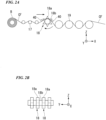
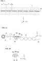
- FIG. 1 is a side view showing the structure of an SMC production apparatus.
- FIG. 2A is a side view showing a structural example of fiber bundle supply unit 10 in the SMC production apparatus shown in FIG. 1 .
- FIG. 2B is a front view of the separation unit seen from the transport direction.
- an XYZ rectangular coordinate system is set and positional relationships among members are described in accordance with the XYZ rectangular coordinate system.
- fiber bundle supply unit 10 is structured to have an opening unit for opening a continuous fiber bundle CF in a width direction (axis (Y) direction) while transporting the fiber bundle in a predetermined direction (hereinafter referred to as a transport direction), and a separation unit for separating the opened fiber bundle CF into multiple fiber bundles CF.
- fiber bundle supply unit 10 includes multiple opening bars 17, multiple rotary blades 18 and multiple godet rollers 19.
- a large-tow fiber bundle CF is opened in its width direction by being drawn from bobbin B in an axis (+X) direction in FIG. 1 (in the horizontally right direction). More specifically, while passing through multiple opening bars 17 of the opening unit, a fiber bundle CF is widened in its width direction by using, for example, heat, abrasion, oscillation or the like at each opening bar 17.
- the opened fiber bundle CF is separated into multiple fiber bundles CF by multiple rotary blades 18 in the separation unit.
- Multiple rotary blades 18 are aligned at predetermined intervals in a width direction of the opened fiber bundle CF (axis (Y) direction).
- a series of multiple teeth 18a are set in a circumferential direction of each rotary blade 18.
- positions of multiple teeth 18a are preferred to correspond to each other in a circumferential direction. By so setting, piercing is done more easily by each of teeth 18a of multiple rotary blades 18 aligned in a width direction of fiber bundle CF.
- spacer members 18b are disposed among rotary blades 18.
- the circumferential surface of each spacer member 18b is positioned slightly above or slightly below the border of each of teeth 18a (blade base). By setting in such a positional relationship, the depth of piercing is adjusted.
- Multiple rotary blades 18 are supported to be rotatable. Accordingly, multiple rotary blades 18 are rotated in a direction the same as the transport direction of a fiber bundle CF while teeth 18a pierce the fiber bundle CF as it is transported.
- Multiple rotary blades 18 may be structured to be driven by a drive motor or the like so as to synchronize the rotation with the transport of a fiber bundle CF.
- a fiber bundle CF is separated in its width direction while rotary blades 18 are rotated so that multiple teeth 18a intermittently pierce a continuous fiber bundle CF. During that time, multiple teeth 18a pierce to the point where spacer members 18b make contact with a continuous fiber bundle CF so as to prevent the fiber bundle CF from continuously being separated by teeth 18a. Accordingly, separated multiple fiber bundles CF are not completely separated from each other, and are partially unseparated. Then, separated fiber bundles CF are supplied toward cutting unit 13 while being guided by multiple godet rollers 19.
- First sheet supply unit 11 supplies continuous first sheet ( S1 ) as it is unwound from first material roll (R1) toward first coating unit 12.
- the SMC production apparatus includes first transport unit 20 which transports first sheet (S1) toward impregnation unit 16.
- First transport unit 20 includes conveyor 23 with endless belt 22 spanned over a pair of pulleys (21a, 21b). Conveyor 23 rotates endless belt 22 circumferentially by rotating paired pulleys (21a, 21b) in the same direction so that first sheet (S1) placed on the surface of endless belt 22 is transported in the axis (+X) direction in FIG. 1 (horizontally toward the right).
- First coating unit 12 includes coater 24 which is positioned directly on first sheet (S1) transported in the axis (+X) direction in FIG. 1 (horizontally toward the right) and supplies paste (P). When first sheet (S1) passes under coater 24 in first coating unit 12, paste (P) is coated at a predetermined thickness on the surface of first sheet (S1).
- a mixture may also be used by adding a filler such as calcium carbonate, a shrinkage-reducing agent, release agent, curing initiator, thickener or the like.
- Cutting unit 13 is positioned on the downstream side of first coating unit 12 in the transport direction and cuts fiber bundles CF supplied from fiber bundle supply unit 10 by using cutter 13A and spreads cut-fiber bundles on past (P).
- Cutter 13A is positioned above first sheet (S1) transported by conveyor 23 and includes guide roller 25, pinch roller 26 and cutter roller 27.
- Guide roller 25 rotates and guides fiber bundle CF supplied from fiber bundle supply unit 10 in the downstream direction.
- Pinch roller 26 sandwiches fiber bundle CF with guide roller 25 and rotates in the direction opposite that of guide roller 25 so as to cooperate with guide roller 25 to bring in separated fiber bundles CF.
- Cutter roller 27 rotates and cuts fiber bundles CF to a predetermined length. Cut fiber bundles CF fall from between guide roller 25 and cutter roller 27 and are spread on first sheet ( S1 ) (paste (P)).
- Second sheet supply unit 14 supplies continuous second sheet (S2) as it is unwound from second material roll (R2) toward second coating unit 15.
- the SMC production apparatus includes second transport unit 28 which transports second sheet (S2) toward impregnation unit 16.
- Second transport unit 28 is positioned above first sheet ( S1 ) transported by conveyor 23 and includes multiple guide rollers 29 . Second transport unit 28 transports second sheet (S2) supplied from second supply unit 14 in the axis (-X) direction in FIG. 1 (horizontally toward the left), and then inverts the direction for transporting second sheet (S2) from below by rotating multiple guide rollers 29 in the axis (+X) direction in FIG. 1 (horizontally toward the right).
- Second coating unit 15 is positioned directly above second sheet (S2) transported in the axis (-X) direction in FIG. 1 (horizontally toward the left) and includes coater 30 for supplying paste (P).
- second sheet (S2) passes through coater 30 so that paste (P) is coated on the surface of second sheet (S2) at a predetermined thickness.
- Impregnation unit 16 is positioned on the downstream side of cutting unit 13 in the transport direction and includes lamination mechanism 31 and compression mechanism 32.
- Lamination mechanism 31 is positioned above downstream-side pulley 21b of conveyor 23 and includes multiple lamination rollers 33.
- Multiple lamination rollers 33 are positioned so as to make contact with the back surface of second sheet (S2) on which paste (P) is coated. Moreover, multiple lamination rollers 33 are positioned in such a way that second sheet (S2) gradually approaches first sheet (S1).
- first sheet ( S1 ) and second sheet (S2) sandwich fiber bundles CF and paste (P) between them and are transported toward compression mechanism 32 in a laminated condition.
- first sheet ( S1 ) and second sheet (S2) laminated together are collectively referred to as laminate sheet (S3).
- Compression mechanism 32 is positioned on the downstream side of first transport unit 20 (conveyor 23), and includes lower conveyor 36A with endless belt 35a spanned between paired pulleys (34a, 34b) and upper conveyor 36B with endless belt 35b spanned between paired pulleys (34c, 34d).
- Lower conveyor 36A and upper conveyor 36B are positioned across from each other while endless belts (35a, 35b) are set to face each other.
- Compression mechanism 32 rotates paired pulleys (34a, 34b) of lower conveyor 36A in the same direction to circle endless belt 35a, while rotating paired pulleys (34c, 34d) of upper conveyor 36B in the same direction so that endless belt 35b circles at the same speed as endless belt 35a but in the opposite direction.
- laminate sheet (S3) sandwiched between endless belts (35a, 35b) is transported in the axis (+X) direction in FIG. 1 (horizontally toward the right).
- Compression mechanism 32 includes multiple lower rollers 37a and multiple upper rollers 37b.
- Multiple lower rollers 37a are positioned to be in contact with the back surface of the abutting portion of endless belt 35a.
- multiple upper rollers 37b are positioned to be in contact with the back surface of the abutting portion of endless belt 35b.
- Multiple lower rollers 37a and multiple upper rollers 37b are alternately positioned in the transport direction of laminate sheet (S3).
- Compression mechanism 32 compresses paste (P) and fiber bundles CF sandwiched between first sheet (S1) and second sheet (S2) using multiple lower rollers 37a and multiple upper rollers 37b while laminate sheet (S3) passes between endless belts (35a, 35b). During that time, paste (P) is impregnated into filaments of fiber bundles CF from both sides sandwiching fiber bundles CF. Accordingly, raw material (R) of SMC is obtained where a thermosetting resin is impregnated in filaments of fiber bundles CF.
- long first sheet (S1) is unwound from first material roll (R1) in a coating step, and paste (P) is coated on first sheet (S1) by first coating unit 12 at a predetermined thickness while first sheet (S1) is transported by first transport unit 20.
- a fiber bundle CF is passed through multiple opening bars 17 so that the fiber bundle CF is widened in a width direction.
- rotary blades 18 rotate so that multiple teeth 18a intermittently pierce the opened fiber bundle CF. Accordingly, the fiber bundle CF is intermittently separated in a longitudinal direction so as to form partially unseparated portions among separated multiple fiber bundles CF.
- the temperature of fiber bundle CF during separation is preferred to be 60°C or lower, more preferably 50 ⁇ 5°C.
- FIG. 3 Separation positions of separated fiber bundles CF are described by referring to FIG. 3 .
- a tow "t" of an opened fiber bundle CF is shown as a thin line
- a separation line of opened fiber bundle CF is shown as a bold line
- a cut line of opened fiber bundle CF to be cut by cutter 13A is shown as a broken line.
- a portion separated by teeth 18a and a portion not separated by teeth 18a are formed alternately in a so-called perforated state as shown in FIG. 3 .
- separated fiber bundles CF are supplied to cutter 13A in a stable condition while avoiding being impacted by meandering fiber bundles CF or askew, meandering or entangled filaments that may occur in fiber bundles CF. Moreover, using relatively low-cost large-tow fiber bundles CF, the production cost of an SMC is reduced.
- fiber bundles CF separated in separation unit 13 are cut by cutter 13A, and spread on paste (P).
- separation and cutting steps fiber bundles are separated and cut to satisfy the condition of (1) described above. By so doing, it is easier to homogeneously disperse reinforcing fibers and to enhance the result of impregnating resin. Accordingly, high quality SMCs are achieved.
- long second sheet (S2) is unwound from second raw material roll (R2) by second sheet supply unit 14, and paste (P) is coated on second sheet (S2) at a predetermined thickness by second coating unit 15.
- lamination mechanism 31 is used to laminate second sheet (S2) on first sheet (S1).
- compression mechanism 32 paste (P) and fiber bundles sandwiched between first sheet (S1) and second sheet (S2) are compressed so as to impregnate the thermosetting resin in filaments of fiber bundles. Accordingly, raw material (R) of an SMC is obtained with the thermosetting resin impregnated in filaments of fiber bundles CF.
- Raw material R of an SMC is wound in a roll and transferred to the next step.
- Raw material R of an SMC is cut to predetermined lengths and shipped as a final product of sheet-type SMCs (fiber-reinforced resin molding material). Note that first sheet (S1) and second sheet (S2) are peeled off from the SMC prior to the molding process of the SMC.
- the present invention is not limited to the above embodiments.
- FIG. 4A is a side view showing another structural example of the fiber bundle supply unit equipped with the SMC production apparatus shown in FIG. 1 .
- FIG. 4B is a front view of the separation unit seen from the transport direction.
- Multiple saw blades 38 are disposed at predetermined intervals in a width direction (axis (Y) direction) of opened fiber bundle CF. Also, in each saw blade 38, a series of multiple teeth 38a are aligned in a direction the same as the transport direction of a fiber bundle CF. In saw blades 38, positions of multiple teeth 38a in the transport direction are preferred to correspond to each other. By so setting, piercing is more easily done by teeth 38a of multiple saw blades 38 aligned in a width direction of a fiber bundle CF.
- spacer members 38b are positioned.
- the upper surface of a spacer member 38b is positioned slightly above the border of each of teeth 38a (blade base).
- paired guide members 40 are positioned on both sides of multiple saw blades 38 in the transport direction. Relative to a fiber bundle CF transported between paired guide members 40, multiple saw blades 38 are positioned on the side opposite where paired guide members 40 are arranged and are set to be capable of making a vertical reciprocating (oscillating) motion between a position where multiple teeth 38a pierce a fiber bundle CF and a position away from the fiber bundle CF.
- a fiber bundle CF is separated in a width direction by multiple teeth 38a intermittently piercing the opened fiber bundle CF while saw blades 38 oscillate vertically (axis (Z) direction).
- multiple teeth 38a pierce to the point where spacer members 38b make contact with a continuous fiber bundle CF so as to prevent the fiber bundle CF from continuously being separated by teeth 38a. Accordingly, the same as in using the aforementioned rotary blades 18, multiple separated fiber bundles CF are partially unseparated.
- separated fiber bundles CF are supplied to cutter 13A in a stable condition while avoiding being impacted by meandering fiber bundles CF or askew, meandering or entangled filaments that may occur in fiber bundles CF.
- teeth (18a, 38a) are not limited specifically, as long as they are capable of intermittently piercing a continuous fiber bundle CF.
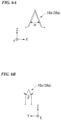
- teeth (18a, 38a) may have such shapes that are shown in FIGs. 5A ⁇ 5E .
- teeth (18a, 38a) may each be single-beveled or double-beveled.
- the timing of teeth (18a, 38a) intermittently piercing a fiber bundle CF is not limited to corresponding with each other, and the timing may be shifted from each other.
- teeth (18a, 38a) are preferred to have angles that satisfy 30° ⁇ ⁇ 590° and 10° ⁇ ⁇ ⁇ 45° (more preferably 20° ⁇ ⁇ ⁇ 30°).
- the thickness of teeth (18a, 38a) is preferred to be set at 0.3-2 mm.
- An SMC was produced by using the above-mentioned SMC apparatus shown in FIGs. 1 and 2 .
- a separation unit having four rotary blades 18 was used.
- each rotary blade 18 a series of six teeth 18a were aligned in a circumferential direction.
- Each of teeth 18a is set to be substantially triangular, having a maximum thickness of 1 mm at the portion that makes contact with a fiber bundle CF, a maximum width of 1 mm at the portion of the blade that makes contact with a fiber bundle, an angle of 64° at the tip of the blade in a width direction (point angle), and an angle of 30° in a thickness direction of the blade (cutting edge angle).
- positions of multiple teeth 18a were set to correspond to each other in a circumferential direction.
- Spacer members 18b are positioned among rotary blades 18, and the width of each spacer member 18b was set at 2.2 mm.
- a carbon fiber bundle (product name: TR 50S15L, number of fibers 15000, made by Mitsubishi Rayon Co., Ltd.) was used for a fiber bundle CF.
- a vinyl ester resin was used as paste (P).
- the fiber bundle CF was widened to have a width of 15 mm by opening bars 17.
- the transport speed of fiber bundle CF during a separation step was 40 m/min.
- 28.3 mm-long separated portions and 0.5 mm-long unseparated portions were alternately formed continuously in a longitudinal direction of the opened fiber bundle CF, while such portions were formed in four rows, being separated at 3 mm-intervals in a width direction of fiber bundle CF.
- Separated fiber bundles CF were cut by cutter 13A every 25.4 mm in a longitudinal direction. Cut fiber bundles CF were spread on paste (P) coated on first sheet (S1). The value of "a/L" was 1.11, and "a/(a+b)" was 0.98.
- An SMC was produced by using the above-mentioned SMC apparatus shown in FIGs. 1 and 2 .
- a separation unit having one rotary blade 18 was used.
- Each of teeth 18a was set to be substantially triangular, having a maximum thickness of 0.5 mm at the portion that makes contact with a fiber bundle CF, a maximum width of 0.5 mm at the portion of the blade that makes contact with a fiber bundle, an angle of 64° at the tip of the blade in a width direction (point angle), and an angle of 30° in a thickness direction of the blade (cutting edge angle).
- positions of multiple teeth 18a were set to correspond to each other in a circumferential direction.
- Spacer members 18b are positioned among rotary blades 18, and the width of each spacer member 18b is set at 24.5 mm.
- a carbon fiber bundle (product name: TRW40 50L, number of fibers 50000, made by Mitsubishi Rayon Co., Ltd.) was used for a fiber bundle CF.
- a vinyl ester resin was used as paste (P).
- the fiber bundle CF was widened to have a width of 25 mm by using opening bars 17.
- the transport speed of fiber bundle CF during a separation step was 40 m/min.
- Separated fiber bundle CF was cut by cutter 13A every 25.4 mm in a longitudinal direction. Cut fiber bundles CF were spread on paste (P) coated on first sheet (S1). The value of "a/L” was 1.11, and "a/(a+b)" was 0.98.
- a carbon fiber bundle (product name: TR 50S15L, number of fibers 15000, made by Mitsubishi Rayon Co., Ltd.) was used.
- the fiber bundle CF was widened to have a width of 15 mm by opening bars 17.
- the transport speed of fiber bundle CF during a separation step was 40 m/min.
- 20.4 mm-long separated portions and 1 mm-long unseparated portions were alternately aligned continuously in a longitudinal direction of the opened fiber bundle CF, while such portions were formed in four rows, being separated at 3-mm intervals in a width direction of the fiber bundle CF.
- the separated fiber bundles CF were cut by cutter 13A every 25.4 mm in a longitudinal direction. Cut fiber bundles CF were spread on paste (P) coated on first sheet (S1). The value of "a/L” was 0.8, and "a/(a+b)" was 0.95.
- a carbon fiber bundle (product name: TR 50S15L, number of fibers 15000, made by Mitsubishi Rayon Co., Ltd.) was used.
- the fiber bundle CF was widened to have a width of 15 mm by opening bars 17.
- the transport speed of fiber bundle CF during a separation step was 40 m/min.
- 28.3 mm-long separated portions and 3.5 mm-long unseparated portions were alternately formed continuously in a longitudinal direction of the opened fiber bundle CF, while such portions were formed in four rows, being separated at 3 mm-intervals in a width direction of the fiber bundle CF.
- Separated fiber bundles CF were cut by cutter 13A every 25.4 mm in a longitudinal direction. Cut fiber bundles CF were spread on paste (P) coated on first sheet (S1). The value of "a/L” was 1.11, and "a/(a+b)" was 0.89.
- a carbon fiber bundle (product name: TR 50S15L, number of fibers 15000, made by Mitsubishi Rayon Co., Ltd.) was used.
- the fiber bundle CF was widened to have a width of 15 mm by opening bars 17.
- the transport speed of fiber bundle CF during a separation step was 40 m/min.
- 28.3 mm-long separated portions and 0 mm-long unseparated portions are alternately aligned continuously in a longitudinal direction of the opened fiber bundle CF, while such portions are formed in four rows, being separated at 3-mm intervals in a width direction of fiber bundle CF.
- Separated fiber bundles CF were cut by cutter 13A every 25.4 mm in a longitudinal direction. Cut fiber bundles CF were spread on paste (P) coated on first sheet (S1). The value of "a/L” was 1.11, and "a/(a+b)" was 1.
- 10 ⁇ fiber bundle supply unit 11 ⁇ first sheet supply unit, 12 ⁇ first coating unit, 13 ⁇ cutting unit, 13A ⁇ cutter, 14 ⁇ second sheet supply unit, 15 ⁇ second coating unit, 16 ⁇ impregnation unit, 18 ⁇ rotary blade, 18a ⁇ tooth, 18b ⁇ spacer member, 20 ⁇ first transport unit, 28 ⁇ second transport unit, 31 ⁇ lamination mechanism, 32 ⁇ compression mechanism, 38 ⁇ saw blade, 38a ⁇ saw tooth, 38b ⁇ spacer member, 40 ⁇ guide member, CF ⁇ fiber bundle, P ⁇ paste (thermosetting resin), S1 ⁇ first sheet, S2 ⁇ second sheet, S3 ⁇ laminated sheet, R ⁇ raw material of SMC (fiber-reinforced resin molding material)
Landscapes
- Engineering & Computer Science (AREA)
- Mechanical Engineering (AREA)
- Chemical & Material Sciences (AREA)
- Composite Materials (AREA)
- Textile Engineering (AREA)
- Reinforced Plastic Materials (AREA)
- Treatment Of Fiber Materials (AREA)
- Yarns And Mechanical Finishing Of Yarns Or Ropes (AREA)
- Perforating, Stamping-Out Or Severing By Means Other Than Cutting (AREA)
Claims (1)
- Verwendung eines kontinuierlichen Faserbündels in einem Verfahren zur Herstellung eines faserverstärkten Harzformmaterials vom Blatttyp, wobei das Verfahren Schneiden des kontinuierlichen Faserbündels in einem Intervall entlang einer Längsrichtung und Imprägnieren eines resultierenden geschnittenen Faserbündels mit einem Harz umfasst, wobei das kontinuierliche Faserbündel einen getrennten Abschnitt und einen ungetrennten Abschnitt entlang der Längsrichtung aufweist und eine Bedingung erfüllt ist, die in der folgenden Formel (1) vorgegeben ist:
 wobei in der Formel (1) "a" eine Länge des getrennten Abschnitts des kontinuierlichen Faserbündels und "L" das Intervall ist,wobei eine in der nachstehenden Formel (2) vorgegebene Bedingung erfüllt ist:
Priority Applications (2)
| Application Number | Priority Date | Filing Date | Title |
|---|---|---|---|
| EP22163187.2A EP4035860B1 (de) | 2015-07-07 | 2016-07-07 | Verwendung eines kontinuierlichen faserbündels in verfahren zur herstellung von faserverstärktem harzformmaterial |
| EP21171166.8A EP3875239B1 (de) | 2015-07-07 | 2016-07-07 | Verfahren zur herstellung von faserverstärktem harzformmaterial |
Applications Claiming Priority (4)
| Application Number | Priority Date | Filing Date | Title |
|---|---|---|---|
| JP2015136084 | 2015-07-07 | ||
| JP2016078937 | 2016-04-11 | ||
| PCT/JP2016/070117 WO2017006989A1 (ja) | 2015-07-07 | 2016-07-07 | 繊維強化樹脂成形材料の製造方法及び製造装置 |
| EP16821457.5A EP3321054B1 (de) | 2015-07-07 | 2016-07-07 | Verfahren und vorrichtung zur herstellung von faserverstärktem harzformmaterial |
Related Parent Applications (2)
| Application Number | Title | Priority Date | Filing Date |
|---|---|---|---|
| EP16821457.5A Division EP3321054B1 (de) | 2015-07-07 | 2016-07-07 | Verfahren und vorrichtung zur herstellung von faserverstärktem harzformmaterial |
| EP16821457.5A Division-Into EP3321054B1 (de) | 2015-07-07 | 2016-07-07 | Verfahren und vorrichtung zur herstellung von faserverstärktem harzformmaterial |
Related Child Applications (4)
| Application Number | Title | Priority Date | Filing Date |
|---|---|---|---|
| EP22163187.2A Division EP4035860B1 (de) | 2015-07-07 | 2016-07-07 | Verwendung eines kontinuierlichen faserbündels in verfahren zur herstellung von faserverstärktem harzformmaterial |
| EP22163187.2A Division-Into EP4035860B1 (de) | 2015-07-07 | 2016-07-07 | Verwendung eines kontinuierlichen faserbündels in verfahren zur herstellung von faserverstärktem harzformmaterial |
| EP21171166.8A Division-Into EP3875239B1 (de) | 2015-07-07 | 2016-07-07 | Verfahren zur herstellung von faserverstärktem harzformmaterial |
| EP21171166.8A Division EP3875239B1 (de) | 2015-07-07 | 2016-07-07 | Verfahren zur herstellung von faserverstärktem harzformmaterial |
Publications (3)
| Publication Number | Publication Date |
|---|---|
| EP3722061A1 EP3722061A1 (de) | 2020-10-14 |
| EP3722061B1 EP3722061B1 (de) | 2021-08-18 |
| EP3722061B2 true EP3722061B2 (de) | 2025-02-26 |
Family
ID=57685649
Family Applications (5)
| Application Number | Title | Priority Date | Filing Date |
|---|---|---|---|
| EP20189574.5A Active EP3750679B1 (de) | 2015-07-07 | 2016-07-07 | Verfahren zur herstellung von faserverstärktem harzmaterial |
| EP22163187.2A Active EP4035860B1 (de) | 2015-07-07 | 2016-07-07 | Verwendung eines kontinuierlichen faserbündels in verfahren zur herstellung von faserverstärktem harzformmaterial |
| EP20178020.2A Active EP3722061B2 (de) | 2015-07-07 | 2016-07-07 | Verwendung eines kontinuierlichen faserbündels in verfahren zur herstellung von faserverstärktem harzformmaterial |
| EP16821457.5A Revoked EP3321054B1 (de) | 2015-07-07 | 2016-07-07 | Verfahren und vorrichtung zur herstellung von faserverstärktem harzformmaterial |
| EP21171166.8A Active EP3875239B1 (de) | 2015-07-07 | 2016-07-07 | Verfahren zur herstellung von faserverstärktem harzformmaterial |
Family Applications Before (2)
| Application Number | Title | Priority Date | Filing Date |
|---|---|---|---|
| EP20189574.5A Active EP3750679B1 (de) | 2015-07-07 | 2016-07-07 | Verfahren zur herstellung von faserverstärktem harzmaterial |
| EP22163187.2A Active EP4035860B1 (de) | 2015-07-07 | 2016-07-07 | Verwendung eines kontinuierlichen faserbündels in verfahren zur herstellung von faserverstärktem harzformmaterial |
Family Applications After (2)
| Application Number | Title | Priority Date | Filing Date |
|---|---|---|---|
| EP16821457.5A Revoked EP3321054B1 (de) | 2015-07-07 | 2016-07-07 | Verfahren und vorrichtung zur herstellung von faserverstärktem harzformmaterial |
| EP21171166.8A Active EP3875239B1 (de) | 2015-07-07 | 2016-07-07 | Verfahren zur herstellung von faserverstärktem harzformmaterial |
Country Status (7)
| Country | Link |
|---|---|
| US (3) | US20180194082A1 (de) |
| EP (5) | EP3750679B1 (de) |
| JP (8) | JP6315101B2 (de) |
| CN (2) | CN112078056B (de) |
| ES (3) | ES2887827T5 (de) |
| HU (2) | HUE055737T2 (de) |
| WO (1) | WO2017006989A1 (de) |
Families Citing this family (23)
| Publication number | Priority date | Publication date | Assignee | Title |
|---|---|---|---|---|
| EP3750679B1 (de) | 2015-07-07 | 2021-08-18 | Mitsubishi Chemical Corporation | Verfahren zur herstellung von faserverstärktem harzmaterial |
| CN108138383A (zh) * | 2015-10-21 | 2018-06-08 | 三菱化学株式会社 | 短切纤维束的制造装置及制造方法、纤维增强树脂成形材料的制造装置及制造方法、碳纤维束用切断刀、以及碳纤维束用旋转刀具 |
| EP4079479A1 (de) * | 2015-12-24 | 2022-10-26 | Mitsubishi Chemical Corporation | Faserverstärktes kunststoffmaterial |
| JP6369622B2 (ja) * | 2015-12-25 | 2018-08-08 | 三菱ケミカル株式会社 | 繊維強化樹脂成形材料の製造方法 |
| EP3408434B1 (de) | 2016-01-26 | 2025-06-25 | Continental Structural Plastics, Inc. | Verfahren und system zur entbündelung eines fasergeleges zur verwendung bei vorformmatten und formzusammensetzungen mit solchen fasern |
| KR102773937B1 (ko) * | 2016-03-15 | 2025-03-04 | 도레이 카부시키가이샤 | 섬유 강화 수지 성형 재료 및 그의 제조 방법 |
| CN109312502B (zh) | 2016-06-20 | 2021-10-29 | 东丽株式会社 | 部分分纤纤维束的制造方法、以及纤维增强树脂成型材料的制造方法 |
| WO2017221656A1 (ja) * | 2016-06-21 | 2017-12-28 | 東レ株式会社 | 部分分繊繊維束とその製造方法、および部分分繊繊維束を用いた繊維強化樹脂成形材料とその製造方法 |
| EP3473759B1 (de) * | 2016-06-21 | 2023-04-05 | Toray Industries, Inc. | Teilweise getrenntes faserbündel, herstellungsverfahren für ein teilweise getrenntes faserbündel, faserverstärktes harzformmaterial mit verwendung des teilweise getrennten faserbündels und herstellungsverfahren für faserverstärktes harzformmaterial mit verwendung des teilweise getrennten faserbündels |
| CN109312505B (zh) * | 2016-06-22 | 2021-07-30 | 东丽株式会社 | 部分分纤纤维束及其制造方法、以及纤维增强树脂成型材料及其制造方法 |
| MX2019008528A (es) * | 2017-02-02 | 2019-09-09 | Toray Industries | Haz de fibra parcialmente separadas y metodo para la fabricacion del mismo, haz de fibras cortadas usando el mismo, y material de formacion de resina reforzada con fibra. |
| EP4431554A3 (de) | 2017-11-20 | 2024-12-11 | Mitsubishi Chemical Corporation | Verfahren und vorrichtung zur herstellung von faserverstärkten harzformmassen |
| FR3075689B1 (fr) * | 2017-12-26 | 2020-12-04 | Plastic Omnium Cie | Procede de fabrication d'un semi-produit pour une piece de vehicule automobile |
| MX2020007734A (es) * | 2018-02-01 | 2020-09-25 | Toray Industries | Haz de fibras de fibra parcialmente separada, material de base intermedio, articulo moldeado y metodo para producir los mismos. |
| JP6773222B2 (ja) * | 2018-04-04 | 2020-10-21 | 三菱ケミカル株式会社 | 繊維強化樹脂成形材料の製造方法及び繊維強化樹脂成形材料の製造装置 |
| CN108688009B (zh) * | 2018-05-23 | 2020-11-20 | 江苏大学 | 一种连续碳纤维增强热塑性树脂基预浸料片制备装置及方法 |
| KR102048276B1 (ko) * | 2018-06-26 | 2020-01-22 | 일성기계공업 주식회사 | Smc 제조방법 및 그 제조장치 |
| CN112639188B (zh) * | 2018-09-28 | 2022-11-08 | 东丽株式会社 | 部分分纤纤维束及其制造方法 |
| CN114981054B (zh) * | 2020-01-21 | 2024-10-18 | 三菱化学株式会社 | Smc的制造方法 |
| EP4163426B1 (de) * | 2020-06-09 | 2025-05-21 | Mitsubishi Chemical Corporation | Verfahren zur herstellung eines kohlenstofffaserbündels mit schlitz, kohlenstofffaserpaket und verfahren zur herstellung eines kohlenstofffaserpakets |
| CN111851050A (zh) * | 2020-07-30 | 2020-10-30 | 程南南 | 一种布匹面料自动化对齐裁剪方法 |
| CN114311732B (zh) * | 2021-12-31 | 2024-06-21 | 江阴四方游泳康复产业股份有限公司 | 一种泳池壁板的成型工艺 |
| US12280555B1 (en) | 2023-10-11 | 2025-04-22 | General Electric Company | Automated fiber placement assembly and method for forming a component |
Citations (4)
| Publication number | Priority date | Publication date | Assignee | Title |
|---|---|---|---|---|
| JP2015136084A (ja) † | 2014-01-20 | 2015-07-27 | 富士通株式会社 | データ送信装置,情報処理装置,データ送信プログラム及びデータ送信方法 |
| WO2016043037A1 (ja) † | 2014-09-17 | 2016-03-24 | 東レ株式会社 | 繊維強化樹脂成形材料 |
| JP2016078937A (ja) † | 2014-10-10 | 2016-05-16 | 博和 伊藤 | チャック式サプリメント簡単取出し器 |
| WO2016104154A1 (ja) † | 2014-12-26 | 2016-06-30 | 東レ株式会社 | 部分分繊繊維束の製造方法および製造装置、部分分繊繊維束 |
Family Cites Families (41)
| Publication number | Priority date | Publication date | Assignee | Title |
|---|---|---|---|---|
| CA1153974A (en) | 1979-12-31 | 1983-09-20 | Francis G. Dwyer | Conversion of olefin containing mixtures to gasoline |
| JPS6248730A (ja) * | 1985-08-26 | 1987-03-03 | Mitsubishi Rayon Co Ltd | 成形用中間体 |
| JPH01163219A (ja) * | 1987-12-19 | 1989-06-27 | Toyota Central Res & Dev Lab Inc | 繊維強化樹脂組成物の製造方法 |
| JPH0757820B2 (ja) * | 1987-12-19 | 1995-06-21 | トヨタ自動車株式会社 | 繊維強化樹脂組成物 |
| US5001172A (en) * | 1987-12-19 | 1991-03-19 | Kabushiki Kaisha Toyota Chuo Kenkyusho | Fiber reinforced plastics |
| US5001956A (en) * | 1989-08-23 | 1991-03-26 | Nitsch J Leonard | Knife for perforating plastic sheet material |
| JP3351155B2 (ja) * | 1995-01-17 | 2002-11-25 | いすゞ自動車株式会社 | Smcシート及びその製造方法並びに装置 |
| US5904793A (en) | 1996-08-14 | 1999-05-18 | Minnesota Mining And Manufacturing Company | Method and equipment for rapid manufacture of loop material |
| US6508906B1 (en) | 2000-03-15 | 2003-01-21 | Patent Holding Company | Carbon fiber-filled sheet molding compound and method of manufacturing same |
| JP3678637B2 (ja) | 2000-09-01 | 2005-08-03 | ユニ・チャーム株式会社 | 連続フィラメントの開繊方法および開繊装置 |
| US6385828B1 (en) | 2001-08-28 | 2002-05-14 | Zoltek Companies, Inc. | Apparatus and method for splitting a tow of fibers |
| US20060204753A1 (en) | 2001-11-21 | 2006-09-14 | Glen Simmonds | Stretch Break Method and Product |
| DE10232147B4 (de) * | 2002-07-16 | 2004-07-15 | Corovin Gmbh | Thermobondiertes und perforertes Vlies |
| DE602004027041D1 (de) | 2003-07-08 | 2010-06-17 | Fukui Prefectural Government | Verfahren zum ausbreiten eines multifilamentbündels und dazugehörende vorrichtung |
| JP4617912B2 (ja) | 2005-02-10 | 2011-01-26 | 東レ株式会社 | 炭素繊維の分割方法、およびシートモールディングコンパウンドの製造方法 |
| CN102815062A (zh) | 2006-11-22 | 2012-12-12 | 福井县 | 热塑性树脂增强片材、热塑性树脂多层增强片材及其制造方法、热塑性树脂多层增强成形品 |
| JP2008254191A (ja) | 2007-03-30 | 2008-10-23 | Honda Motor Co Ltd | 炭素繊維複合材料製造装置、これを用いた炭素繊維複合材料製造方法および炭素繊維複合材料 |
| ES2837455T3 (es) * | 2007-06-04 | 2021-06-30 | Toray Industries | Haz de fibras troceadas, material de moldeo y plástico reforzado con fibras, y proceso para producirlos |
| JP2009191238A (ja) | 2008-02-18 | 2009-08-27 | Honda Motor Co Ltd | 炭素繊維強化樹脂成形材料の製造方法及び炭素繊維強化樹脂成形材料 |
| JP5569708B2 (ja) * | 2009-01-15 | 2014-08-13 | 三菱レイヨン株式会社 | シートモールディングコンパウンドの製造方法 |
| JP2011241494A (ja) * | 2010-05-17 | 2011-12-01 | Toyota Motor Corp | 開繊シートの製造装置及びその製造方法 |
| WO2012002417A1 (ja) | 2010-06-30 | 2012-01-05 | 東レ株式会社 | シート状プリプレグの製造方法および装置 |
| CN103314041B (zh) * | 2011-01-14 | 2015-11-25 | 东丽株式会社 | 成型材料、预浸料、纤维强化复合材料和纤维强化复合材料叠层体以及纤维强化成型基材的制造方法 |
| US20120213997A1 (en) * | 2011-02-21 | 2012-08-23 | United States Council For Automotive Research | Fiber tow treatment apparatus and system |
| JP5956150B2 (ja) * | 2011-12-26 | 2016-07-27 | 帝人株式会社 | 炭素繊維強化熱可塑性樹脂およびその成形品の製造方法 |
| JP2013241491A (ja) * | 2012-05-18 | 2013-12-05 | Sumitomo Bakelite Co Ltd | 積層シートの製造方法および積層シートの製造装置 |
| CN102704131B (zh) | 2012-06-26 | 2014-10-15 | 东华大学 | 非对称展丝分束的再展与集束复合展丝器、方法及应用 |
| WO2014017612A1 (ja) | 2012-07-26 | 2014-01-30 | 帝人株式会社 | ランダムマットおよび繊維強化複合材料成形体 |
| RU2558904C1 (ru) * | 2012-08-01 | 2015-08-10 | Тейдзин Лимитед | Мат с произвольной ориентацией волокон и формованный продукт из армированного волокном композитного материала |
| ES2531582T3 (es) * | 2012-11-05 | 2015-03-17 | Toho Tenax Europe Gmbh | Procedimiento para fabricar preformas fibrosas |
| JP2014210991A (ja) * | 2013-04-18 | 2014-11-13 | 帝人株式会社 | 強化繊維マットおよび強化繊維マットの製造方法 |
| WO2014208626A1 (ja) | 2013-06-26 | 2014-12-31 | 帝人株式会社 | ランダムマット、繊維強化複合材料成形体、および炭素繊維マット |
| JP6077577B2 (ja) | 2015-02-26 | 2017-02-08 | 帝人株式会社 | 補強繊維ストランド分繊糸の製造方法 |
| CN107406600B (zh) * | 2015-03-30 | 2020-08-07 | 东丽株式会社 | 纤维增强树脂成型材料及其制造方法 |
| EP3750679B1 (de) | 2015-07-07 | 2021-08-18 | Mitsubishi Chemical Corporation | Verfahren zur herstellung von faserverstärktem harzmaterial |
| EP4079479A1 (de) | 2015-12-24 | 2022-10-26 | Mitsubishi Chemical Corporation | Faserverstärktes kunststoffmaterial |
| KR102773937B1 (ko) | 2016-03-15 | 2025-03-04 | 도레이 카부시키가이샤 | 섬유 강화 수지 성형 재료 및 그의 제조 방법 |
| CN109312502B (zh) | 2016-06-20 | 2021-10-29 | 东丽株式会社 | 部分分纤纤维束的制造方法、以及纤维增强树脂成型材料的制造方法 |
| EP3473759B1 (de) | 2016-06-21 | 2023-04-05 | Toray Industries, Inc. | Teilweise getrenntes faserbündel, herstellungsverfahren für ein teilweise getrenntes faserbündel, faserverstärktes harzformmaterial mit verwendung des teilweise getrennten faserbündels und herstellungsverfahren für faserverstärktes harzformmaterial mit verwendung des teilweise getrennten faserbündels |
| WO2017221656A1 (ja) | 2016-06-21 | 2017-12-28 | 東レ株式会社 | 部分分繊繊維束とその製造方法、および部分分繊繊維束を用いた繊維強化樹脂成形材料とその製造方法 |
| CN109312505B (zh) | 2016-06-22 | 2021-07-30 | 东丽株式会社 | 部分分纤纤维束及其制造方法、以及纤维增强树脂成型材料及其制造方法 |
-
2016
- 2016-07-07 EP EP20189574.5A patent/EP3750679B1/de active Active
- 2016-07-07 EP EP22163187.2A patent/EP4035860B1/de active Active
- 2016-07-07 EP EP20178020.2A patent/EP3722061B2/de active Active
- 2016-07-07 JP JP2016548745A patent/JP6315101B2/ja active Active
- 2016-07-07 WO PCT/JP2016/070117 patent/WO2017006989A1/ja not_active Ceased
- 2016-07-07 HU HUE20189574A patent/HUE055737T2/hu unknown
- 2016-07-07 ES ES20178020T patent/ES2887827T5/es active Active
- 2016-07-07 ES ES21171166T patent/ES2979188T3/es active Active
- 2016-07-07 ES ES20189574T patent/ES2887828T3/es active Active
- 2016-07-07 US US15/741,615 patent/US20180194082A1/en not_active Abandoned
- 2016-07-07 EP EP16821457.5A patent/EP3321054B1/de not_active Revoked
- 2016-07-07 CN CN202010921119.8A patent/CN112078056B/zh active Active
- 2016-07-07 CN CN201680039647.2A patent/CN107848146B/zh active Active
- 2016-07-07 EP EP21171166.8A patent/EP3875239B1/de active Active
- 2016-07-07 HU HUE22163187A patent/HUE069950T2/hu unknown
-
2017
- 2017-07-06 JP JP2017133132A patent/JP2017218717A/ja active Pending
-
2020
- 2020-07-27 JP JP2020126738A patent/JP7006734B2/ja active Active
- 2020-07-27 JP JP2020126737A patent/JP2020186510A/ja active Pending
- 2020-11-11 JP JP2020187934A patent/JP7044148B2/ja active Active
-
2021
- 2021-03-29 US US17/216,294 patent/US11518116B2/en active Active
- 2021-12-10 JP JP2021201144A patent/JP7201063B2/ja active Active
-
2022
- 2022-10-31 US US17/978,204 patent/US11919255B2/en active Active
- 2022-12-22 JP JP2022205751A patent/JP7509193B2/ja active Active
-
2024
- 2024-06-19 JP JP2024099015A patent/JP2024111168A/ja active Pending
Patent Citations (5)
| Publication number | Priority date | Publication date | Assignee | Title |
|---|---|---|---|---|
| JP2015136084A (ja) † | 2014-01-20 | 2015-07-27 | 富士通株式会社 | データ送信装置,情報処理装置,データ送信プログラム及びデータ送信方法 |
| WO2016043037A1 (ja) † | 2014-09-17 | 2016-03-24 | 東レ株式会社 | 繊維強化樹脂成形材料 |
| JP2016078937A (ja) † | 2014-10-10 | 2016-05-16 | 博和 伊藤 | チャック式サプリメント簡単取出し器 |
| WO2016104154A1 (ja) † | 2014-12-26 | 2016-06-30 | 東レ株式会社 | 部分分繊繊維束の製造方法および製造装置、部分分繊繊維束 |
| EP3239372A1 (de) † | 2014-12-26 | 2017-11-01 | Toray Industries, Inc. | Verfahren zur herstellung und herstellungsvorrichtung für partielles spaltfaser-faserbündel und partielles spaltfaser-faserbündel |
Also Published As
Similar Documents
| Publication | Publication Date | Title |
|---|---|---|
| EP3722061B2 (de) | Verwendung eines kontinuierlichen faserbündels in verfahren zur herstellung von faserverstärktem harzformmaterial | |
| US11643513B2 (en) | Method and device for manufacturing fiber-reinforced resin molding material | |
| JP6962492B1 (ja) | 繊維強化樹脂成形材料の製造方法及び繊維強化樹脂成形材料の製造装置 |
Legal Events
| Date | Code | Title | Description |
|---|---|---|---|
| PUAI | Public reference made under article 153(3) epc to a published international application that has entered the european phase |
Free format text: ORIGINAL CODE: 0009012 |
|
| STAA | Information on the status of an ep patent application or granted ep patent |
Free format text: STATUS: REQUEST FOR EXAMINATION WAS MADE |
|
| 17P | Request for examination filed |
Effective date: 20200603 |
|
| AC | Divisional application: reference to earlier application |
Ref document number: 3321054 Country of ref document: EP Kind code of ref document: P |
|
| AK | Designated contracting states |
Kind code of ref document: A1 Designated state(s): AL AT BE BG CH CY CZ DE DK EE ES FI FR GB GR HR HU IE IS IT LI LT LU LV MC MK MT NL NO PL PT RO RS SE SI SK SM TR |
|
| GRAP | Despatch of communication of intention to grant a patent |
Free format text: ORIGINAL CODE: EPIDOSNIGR1 |
|
| STAA | Information on the status of an ep patent application or granted ep patent |
Free format text: STATUS: GRANT OF PATENT IS INTENDED |
|
| RIC1 | Information provided on ipc code assigned before grant |
Ipc: B29K 101/10 20060101ALN20210113BHEP Ipc: B29B 15/12 20060101AFI20210113BHEP Ipc: D01D 11/02 20060101ALI20210113BHEP Ipc: B29K 105/06 20060101ALN20210113BHEP |
|
| INTG | Intention to grant announced |
Effective date: 20210129 |
|
| GRAJ | Information related to disapproval of communication of intention to grant by the applicant or resumption of examination proceedings by the epo deleted |
Free format text: ORIGINAL CODE: EPIDOSDIGR1 |
|
| STAA | Information on the status of an ep patent application or granted ep patent |
Free format text: STATUS: REQUEST FOR EXAMINATION WAS MADE |
|
| GRAP | Despatch of communication of intention to grant a patent |
Free format text: ORIGINAL CODE: EPIDOSNIGR1 |
|
| STAA | Information on the status of an ep patent application or granted ep patent |
Free format text: STATUS: GRANT OF PATENT IS INTENDED |
|
| INTC | Intention to grant announced (deleted) | ||
| RIC1 | Information provided on ipc code assigned before grant |
Ipc: B29K 105/06 20060101ALN20210415BHEP Ipc: B29K 101/10 20060101ALN20210415BHEP Ipc: D01D 11/02 20060101ALI20210415BHEP Ipc: B29B 15/12 20060101AFI20210415BHEP |
|
| INTG | Intention to grant announced |
Effective date: 20210429 |
|
| RIC1 | Information provided on ipc code assigned before grant |
Ipc: B29K 105/06 20060101ALN20210420BHEP Ipc: B29K 101/10 20060101ALN20210420BHEP Ipc: D01D 11/02 20060101ALI20210420BHEP Ipc: B29B 15/12 20060101AFI20210420BHEP |
|
| GRAS | Grant fee paid |
Free format text: ORIGINAL CODE: EPIDOSNIGR3 |
|
| GRAA | (expected) grant |
Free format text: ORIGINAL CODE: 0009210 |
|
| STAA | Information on the status of an ep patent application or granted ep patent |
Free format text: STATUS: THE PATENT HAS BEEN GRANTED |
|
| AC | Divisional application: reference to earlier application |
Ref document number: 3321054 Country of ref document: EP Kind code of ref document: P |
|
| AK | Designated contracting states |
Kind code of ref document: B1 Designated state(s): AL AT BE BG CH CY CZ DE DK EE ES FI FR GB GR HR HU IE IS IT LI LT LU LV MC MK MT NL NO PL PT RO RS SE SI SK SM TR |
|
| REG | Reference to a national code |
Ref country code: GB Ref legal event code: FG4D |
|
| REG | Reference to a national code |
Ref country code: CH Ref legal event code: EP |
|
| REG | Reference to a national code |
Ref country code: DE Ref legal event code: R096 Ref document number: 602016062596 Country of ref document: DE |
|
| REG | Reference to a national code |
Ref country code: IE Ref legal event code: FG4D Ref country code: AT Ref legal event code: REF Ref document number: 1421228 Country of ref document: AT Kind code of ref document: T Effective date: 20210915 |
|
| REG | Reference to a national code |
Ref country code: LT Ref legal event code: MG9D |
|
| REG | Reference to a national code |
Ref country code: NL Ref legal event code: MP Effective date: 20210818 |
|
| REG | Reference to a national code |
Ref country code: ES Ref legal event code: FG2A Ref document number: 2887827 Country of ref document: ES Kind code of ref document: T3 Effective date: 20211228 |
|
| REG | Reference to a national code |
Ref country code: AT Ref legal event code: MK05 Ref document number: 1421228 Country of ref document: AT Kind code of ref document: T Effective date: 20210818 |
|
| PG25 | Lapsed in a contracting state [announced via postgrant information from national office to epo] |
Ref country code: SE Free format text: LAPSE BECAUSE OF FAILURE TO SUBMIT A TRANSLATION OF THE DESCRIPTION OR TO PAY THE FEE WITHIN THE PRESCRIBED TIME-LIMIT Effective date: 20210818 Ref country code: RS Free format text: LAPSE BECAUSE OF FAILURE TO SUBMIT A TRANSLATION OF THE DESCRIPTION OR TO PAY THE FEE WITHIN THE PRESCRIBED TIME-LIMIT Effective date: 20210818 Ref country code: LT Free format text: LAPSE BECAUSE OF FAILURE TO SUBMIT A TRANSLATION OF THE DESCRIPTION OR TO PAY THE FEE WITHIN THE PRESCRIBED TIME-LIMIT Effective date: 20210818 Ref country code: BG Free format text: LAPSE BECAUSE OF FAILURE TO SUBMIT A TRANSLATION OF THE DESCRIPTION OR TO PAY THE FEE WITHIN THE PRESCRIBED TIME-LIMIT Effective date: 20211118 Ref country code: AT Free format text: LAPSE BECAUSE OF FAILURE TO SUBMIT A TRANSLATION OF THE DESCRIPTION OR TO PAY THE FEE WITHIN THE PRESCRIBED TIME-LIMIT Effective date: 20210818 Ref country code: FI Free format text: LAPSE BECAUSE OF FAILURE TO SUBMIT A TRANSLATION OF THE DESCRIPTION OR TO PAY THE FEE WITHIN THE PRESCRIBED TIME-LIMIT Effective date: 20210818 Ref country code: HR Free format text: LAPSE BECAUSE OF FAILURE TO SUBMIT A TRANSLATION OF THE DESCRIPTION OR TO PAY THE FEE WITHIN THE PRESCRIBED TIME-LIMIT Effective date: 20210818 Ref country code: NO Free format text: LAPSE BECAUSE OF FAILURE TO SUBMIT A TRANSLATION OF THE DESCRIPTION OR TO PAY THE FEE WITHIN THE PRESCRIBED TIME-LIMIT Effective date: 20211118 Ref country code: PT Free format text: LAPSE BECAUSE OF FAILURE TO SUBMIT A TRANSLATION OF THE DESCRIPTION OR TO PAY THE FEE WITHIN THE PRESCRIBED TIME-LIMIT Effective date: 20211220 |
|
| PG25 | Lapsed in a contracting state [announced via postgrant information from national office to epo] |
Ref country code: PL Free format text: LAPSE BECAUSE OF FAILURE TO SUBMIT A TRANSLATION OF THE DESCRIPTION OR TO PAY THE FEE WITHIN THE PRESCRIBED TIME-LIMIT Effective date: 20210818 Ref country code: LV Free format text: LAPSE BECAUSE OF FAILURE TO SUBMIT A TRANSLATION OF THE DESCRIPTION OR TO PAY THE FEE WITHIN THE PRESCRIBED TIME-LIMIT Effective date: 20210818 Ref country code: GR Free format text: LAPSE BECAUSE OF FAILURE TO SUBMIT A TRANSLATION OF THE DESCRIPTION OR TO PAY THE FEE WITHIN THE PRESCRIBED TIME-LIMIT Effective date: 20211119 |
|
| PG25 | Lapsed in a contracting state [announced via postgrant information from national office to epo] |
Ref country code: NL Free format text: LAPSE BECAUSE OF FAILURE TO SUBMIT A TRANSLATION OF THE DESCRIPTION OR TO PAY THE FEE WITHIN THE PRESCRIBED TIME-LIMIT Effective date: 20210818 |
|
| PG25 | Lapsed in a contracting state [announced via postgrant information from national office to epo] |
Ref country code: DK Free format text: LAPSE BECAUSE OF FAILURE TO SUBMIT A TRANSLATION OF THE DESCRIPTION OR TO PAY THE FEE WITHIN THE PRESCRIBED TIME-LIMIT Effective date: 20210818 |
|
| REG | Reference to a national code |
Ref country code: DE Ref legal event code: R026 Ref document number: 602016062596 Country of ref document: DE |
|
| PLBI | Opposition filed |
Free format text: ORIGINAL CODE: 0009260 |
|
| PG25 | Lapsed in a contracting state [announced via postgrant information from national office to epo] |
Ref country code: SM Free format text: LAPSE BECAUSE OF FAILURE TO SUBMIT A TRANSLATION OF THE DESCRIPTION OR TO PAY THE FEE WITHIN THE PRESCRIBED TIME-LIMIT Effective date: 20210818 Ref country code: SK Free format text: LAPSE BECAUSE OF FAILURE TO SUBMIT A TRANSLATION OF THE DESCRIPTION OR TO PAY THE FEE WITHIN THE PRESCRIBED TIME-LIMIT Effective date: 20210818 Ref country code: RO Free format text: LAPSE BECAUSE OF FAILURE TO SUBMIT A TRANSLATION OF THE DESCRIPTION OR TO PAY THE FEE WITHIN THE PRESCRIBED TIME-LIMIT Effective date: 20210818 Ref country code: EE Free format text: LAPSE BECAUSE OF FAILURE TO SUBMIT A TRANSLATION OF THE DESCRIPTION OR TO PAY THE FEE WITHIN THE PRESCRIBED TIME-LIMIT Effective date: 20210818 Ref country code: CZ Free format text: LAPSE BECAUSE OF FAILURE TO SUBMIT A TRANSLATION OF THE DESCRIPTION OR TO PAY THE FEE WITHIN THE PRESCRIBED TIME-LIMIT Effective date: 20210818 Ref country code: AL Free format text: LAPSE BECAUSE OF FAILURE TO SUBMIT A TRANSLATION OF THE DESCRIPTION OR TO PAY THE FEE WITHIN THE PRESCRIBED TIME-LIMIT Effective date: 20210818 |
|
| PLAX | Notice of opposition and request to file observation + time limit sent |
Free format text: ORIGINAL CODE: EPIDOSNOBS2 |
|
| 26 | Opposition filed |
Opponent name: TORAY INDUSTRIES, INC. Effective date: 20220512 |
|
| PG25 | Lapsed in a contracting state [announced via postgrant information from national office to epo] |
Ref country code: SI Free format text: LAPSE BECAUSE OF FAILURE TO SUBMIT A TRANSLATION OF THE DESCRIPTION OR TO PAY THE FEE WITHIN THE PRESCRIBED TIME-LIMIT Effective date: 20210818 |
|
| PLBB | Reply of patent proprietor to notice(s) of opposition received |
Free format text: ORIGINAL CODE: EPIDOSNOBS3 |
|
| PG25 | Lapsed in a contracting state [announced via postgrant information from national office to epo] |
Ref country code: MC Free format text: LAPSE BECAUSE OF FAILURE TO SUBMIT A TRANSLATION OF THE DESCRIPTION OR TO PAY THE FEE WITHIN THE PRESCRIBED TIME-LIMIT Effective date: 20210818 |
|
| REG | Reference to a national code |
Ref country code: CH Ref legal event code: PL |
|
| GBPC | Gb: european patent ceased through non-payment of renewal fee |
Effective date: 20220707 |
|
| REG | Reference to a national code |
Ref country code: BE Ref legal event code: MM Effective date: 20220731 |
|
| PG25 | Lapsed in a contracting state [announced via postgrant information from national office to epo] |
Ref country code: LU Free format text: LAPSE BECAUSE OF NON-PAYMENT OF DUE FEES Effective date: 20220707 Ref country code: LI Free format text: LAPSE BECAUSE OF NON-PAYMENT OF DUE FEES Effective date: 20220731 Ref country code: CH Free format text: LAPSE BECAUSE OF NON-PAYMENT OF DUE FEES Effective date: 20220731 |
|
| PG25 | Lapsed in a contracting state [announced via postgrant information from national office to epo] |
Ref country code: GB Free format text: LAPSE BECAUSE OF NON-PAYMENT OF DUE FEES Effective date: 20220707 Ref country code: BE Free format text: LAPSE BECAUSE OF NON-PAYMENT OF DUE FEES Effective date: 20220731 |
|
| P01 | Opt-out of the competence of the unified patent court (upc) registered |
Effective date: 20230522 |
|
| PG25 | Lapsed in a contracting state [announced via postgrant information from national office to epo] |
Ref country code: IE Free format text: LAPSE BECAUSE OF NON-PAYMENT OF DUE FEES Effective date: 20220707 |
|
| PG25 | Lapsed in a contracting state [announced via postgrant information from national office to epo] |
Ref country code: MK Free format text: LAPSE BECAUSE OF FAILURE TO SUBMIT A TRANSLATION OF THE DESCRIPTION OR TO PAY THE FEE WITHIN THE PRESCRIBED TIME-LIMIT Effective date: 20210818 Ref country code: CY Free format text: LAPSE BECAUSE OF FAILURE TO SUBMIT A TRANSLATION OF THE DESCRIPTION OR TO PAY THE FEE WITHIN THE PRESCRIBED TIME-LIMIT Effective date: 20210818 |
|
| PG25 | Lapsed in a contracting state [announced via postgrant information from national office to epo] |
Ref country code: HU Free format text: LAPSE BECAUSE OF FAILURE TO SUBMIT A TRANSLATION OF THE DESCRIPTION OR TO PAY THE FEE WITHIN THE PRESCRIBED TIME-LIMIT; INVALID AB INITIO Effective date: 20160707 |
|
| APBP | Date of receipt of notice of appeal recorded |
Free format text: ORIGINAL CODE: EPIDOSNNOA2O |
|
| APAH | Appeal reference modified |
Free format text: ORIGINAL CODE: EPIDOSCREFNO |
|
| APAY | Date of receipt of notice of appeal deleted |
Free format text: ORIGINAL CODE: EPIDOSDNOA2O |
|
| APBM | Appeal reference recorded |
Free format text: ORIGINAL CODE: EPIDOSNREFNO |
|
| APBP | Date of receipt of notice of appeal recorded |
Free format text: ORIGINAL CODE: EPIDOSNNOA2O |
|
| PG25 | Lapsed in a contracting state [announced via postgrant information from national office to epo] |
Ref country code: MT Free format text: LAPSE BECAUSE OF FAILURE TO SUBMIT A TRANSLATION OF THE DESCRIPTION OR TO PAY THE FEE WITHIN THE PRESCRIBED TIME-LIMIT Effective date: 20210818 |
|
| APBU | Appeal procedure closed |
Free format text: ORIGINAL CODE: EPIDOSNNOA9O |
|
| PUAH | Patent maintained in amended form |
Free format text: ORIGINAL CODE: 0009272 |
|
| STAA | Information on the status of an ep patent application or granted ep patent |
Free format text: STATUS: PATENT MAINTAINED AS AMENDED |
|
| 27A | Patent maintained in amended form |
Effective date: 20250226 |
|
| AK | Designated contracting states |
Kind code of ref document: B2 Designated state(s): AL AT BE BG CH CY CZ DE DK EE ES FI FR GB GR HR HU IE IS IT LI LT LU LV MC MK MT NL NO PL PT RO RS SE SI SK SM TR |
|
| REG | Reference to a national code |
Ref country code: DE Ref legal event code: R102 Ref document number: 602016062596 Country of ref document: DE |
|
| REG | Reference to a national code |
Ref country code: ES Ref legal event code: DC2A Ref document number: 2887827 Country of ref document: ES Kind code of ref document: T5 Effective date: 20250509 |
|
| PGFP | Annual fee paid to national office [announced via postgrant information from national office to epo] |
Ref country code: ES Payment date: 20250801 Year of fee payment: 10 |
|
| PGFP | Annual fee paid to national office [announced via postgrant information from national office to epo] |
Ref country code: DE Payment date: 20250728 Year of fee payment: 10 |
|
| PGFP | Annual fee paid to national office [announced via postgrant information from national office to epo] |
Ref country code: IT Payment date: 20250626 Year of fee payment: 10 |
|
| PGFP | Annual fee paid to national office [announced via postgrant information from national office to epo] |
Ref country code: FR Payment date: 20250707 Year of fee payment: 10 |
|
| PG25 | Lapsed in a contracting state [announced via postgrant information from national office to epo] |
Ref country code: TR Free format text: LAPSE BECAUSE OF FAILURE TO SUBMIT A TRANSLATION OF THE DESCRIPTION OR TO PAY THE FEE WITHIN THE PRESCRIBED TIME-LIMIT Effective date: 20210818 |