EP3721964A1 - Fabric layer, flat material, filter element, filter and method for producing a fabric layer - Google Patents
Fabric layer, flat material, filter element, filter and method for producing a fabric layer Download PDFInfo
- Publication number
- EP3721964A1 EP3721964A1 EP19195274.6A EP19195274A EP3721964A1 EP 3721964 A1 EP3721964 A1 EP 3721964A1 EP 19195274 A EP19195274 A EP 19195274A EP 3721964 A1 EP3721964 A1 EP 3721964A1
- Authority
- EP
- European Patent Office
- Prior art keywords
- fabric
- weave
- strip
- flat material
- type
- Prior art date
- Legal status (The legal status is an assumption and is not a legal conclusion. Google has not performed a legal analysis and makes no representation as to the accuracy of the status listed.)
- Pending
Links
- 239000004744 fabric Substances 0.000 title claims abstract description 288
- 239000000463 material Substances 0.000 title claims abstract description 69
- 238000004519 manufacturing process Methods 0.000 title claims description 10
- 230000001681 protective effect Effects 0.000 claims abstract description 11
- 239000012530 fluid Substances 0.000 claims abstract description 10
- 239000010410 layer Substances 0.000 claims description 105
- 239000002346 layers by function Substances 0.000 claims description 4
- 238000009941 weaving Methods 0.000 claims description 4
- 239000000853 adhesive Substances 0.000 claims description 3
- 230000001070 adhesive effect Effects 0.000 claims description 3
- 239000004033 plastic Substances 0.000 claims description 3
- 239000000126 substance Substances 0.000 claims description 3
- 239000002184 metal Substances 0.000 claims description 2
- 238000012545 processing Methods 0.000 description 10
- 230000008901 benefit Effects 0.000 description 6
- 230000015572 biosynthetic process Effects 0.000 description 5
- 238000000034 method Methods 0.000 description 4
- 230000008859 change Effects 0.000 description 3
- 238000011045 prefiltration Methods 0.000 description 3
- 230000037303 wrinkles Effects 0.000 description 3
- 239000002131 composite material Substances 0.000 description 2
- 238000001914 filtration Methods 0.000 description 2
- 239000007788 liquid Substances 0.000 description 2
- 239000007795 chemical reaction product Substances 0.000 description 1
- 230000000694 effects Effects 0.000 description 1
- 239000011152 fibreglass Substances 0.000 description 1
- 230000012447 hatching Effects 0.000 description 1
- 230000001771 impaired effect Effects 0.000 description 1
- 230000006872 improvement Effects 0.000 description 1
- 239000013067 intermediate product Substances 0.000 description 1
- 230000009191 jumping Effects 0.000 description 1
- 239000002245 particle Substances 0.000 description 1
- 230000008092 positive effect Effects 0.000 description 1
- 238000012805 post-processing Methods 0.000 description 1
- 230000008569 process Effects 0.000 description 1
- 230000000717 retained effect Effects 0.000 description 1
- 230000033764 rhythmic process Effects 0.000 description 1
- 238000000926 separation method Methods 0.000 description 1
- 230000007704 transition Effects 0.000 description 1
- 238000011144 upstream manufacturing Methods 0.000 description 1
- 239000002759 woven fabric Substances 0.000 description 1
Images
Classifications
-
- D—TEXTILES; PAPER
- D03—WEAVING
- D03D—WOVEN FABRICS; METHODS OF WEAVING; LOOMS
- D03D1/00—Woven fabrics designed to make specified articles
-
- B—PERFORMING OPERATIONS; TRANSPORTING
- B01—PHYSICAL OR CHEMICAL PROCESSES OR APPARATUS IN GENERAL
- B01D—SEPARATION
- B01D39/00—Filtering material for liquid or gaseous fluids
- B01D39/08—Filter cloth, i.e. woven, knitted or interlaced material
- B01D39/083—Filter cloth, i.e. woven, knitted or interlaced material of organic material
-
- B—PERFORMING OPERATIONS; TRANSPORTING
- B01—PHYSICAL OR CHEMICAL PROCESSES OR APPARATUS IN GENERAL
- B01D—SEPARATION
- B01D29/00—Filters with filtering elements stationary during filtration, e.g. pressure or suction filters, not covered by groups B01D24/00 - B01D27/00; Filtering elements therefor
- B01D29/11—Filters with filtering elements stationary during filtration, e.g. pressure or suction filters, not covered by groups B01D24/00 - B01D27/00; Filtering elements therefor with bag, cage, hose, tube, sleeve or like filtering elements
- B01D29/13—Supported filter elements
- B01D29/15—Supported filter elements arranged for inward flow filtration
- B01D29/21—Supported filter elements arranged for inward flow filtration with corrugated, folded or wound sheets
-
- B—PERFORMING OPERATIONS; TRANSPORTING
- B01—PHYSICAL OR CHEMICAL PROCESSES OR APPARATUS IN GENERAL
- B01D—SEPARATION
- B01D29/00—Filters with filtering elements stationary during filtration, e.g. pressure or suction filters, not covered by groups B01D24/00 - B01D27/00; Filtering elements therefor
- B01D29/11—Filters with filtering elements stationary during filtration, e.g. pressure or suction filters, not covered by groups B01D24/00 - B01D27/00; Filtering elements therefor with bag, cage, hose, tube, sleeve or like filtering elements
- B01D29/13—Supported filter elements
- B01D29/23—Supported filter elements arranged for outward flow filtration
-
- B—PERFORMING OPERATIONS; TRANSPORTING
- B01—PHYSICAL OR CHEMICAL PROCESSES OR APPARATUS IN GENERAL
- B01D—SEPARATION
- B01D39/00—Filtering material for liquid or gaseous fluids
- B01D39/08—Filter cloth, i.e. woven, knitted or interlaced material
-
- B—PERFORMING OPERATIONS; TRANSPORTING
- B01—PHYSICAL OR CHEMICAL PROCESSES OR APPARATUS IN GENERAL
- B01D—SEPARATION
- B01D39/00—Filtering material for liquid or gaseous fluids
- B01D39/08—Filter cloth, i.e. woven, knitted or interlaced material
- B01D39/086—Filter cloth, i.e. woven, knitted or interlaced material of inorganic material
-
- B—PERFORMING OPERATIONS; TRANSPORTING
- B01—PHYSICAL OR CHEMICAL PROCESSES OR APPARATUS IN GENERAL
- B01D—SEPARATION
- B01D46/00—Filters or filtering processes specially modified for separating dispersed particles from gases or vapours
- B01D46/52—Particle separators, e.g. dust precipitators, using filters embodying folded corrugated or wound sheet material
- B01D46/521—Particle separators, e.g. dust precipitators, using filters embodying folded corrugated or wound sheet material using folded, pleated material
-
- D—TEXTILES; PAPER
- D03—WEAVING
- D03D—WOVEN FABRICS; METHODS OF WEAVING; LOOMS
- D03D13/00—Woven fabrics characterised by the special disposition of the warp or weft threads, e.g. with curved weft threads, with discontinuous warp threads, with diagonal warp or weft
- D03D13/004—Woven fabrics characterised by the special disposition of the warp or weft threads, e.g. with curved weft threads, with discontinuous warp threads, with diagonal warp or weft with weave pattern being non-standard or providing special effects
-
- D—TEXTILES; PAPER
- D03—WEAVING
- D03D—WOVEN FABRICS; METHODS OF WEAVING; LOOMS
- D03D15/00—Woven fabrics characterised by the material, structure or properties of the fibres, filaments, yarns, threads or other warp or weft elements used
-
- B—PERFORMING OPERATIONS; TRANSPORTING
- B01—PHYSICAL OR CHEMICAL PROCESSES OR APPARATUS IN GENERAL
- B01D—SEPARATION
- B01D2239/00—Aspects relating to filtering material for liquid or gaseous fluids
- B01D2239/06—Filter cloth, e.g. knitted, woven non-woven; self-supported material
- B01D2239/0604—Arrangement of the fibres in the filtering material
- B01D2239/064—The fibres being mixed
-
- B—PERFORMING OPERATIONS; TRANSPORTING
- B01—PHYSICAL OR CHEMICAL PROCESSES OR APPARATUS IN GENERAL
- B01D—SEPARATION
- B01D2239/00—Aspects relating to filtering material for liquid or gaseous fluids
- B01D2239/06—Filter cloth, e.g. knitted, woven non-woven; self-supported material
- B01D2239/065—More than one layer present in the filtering material
- B01D2239/0654—Support layers
-
- D—TEXTILES; PAPER
- D10—INDEXING SCHEME ASSOCIATED WITH SUBLASSES OF SECTION D, RELATING TO TEXTILES
- D10B—INDEXING SCHEME ASSOCIATED WITH SUBLASSES OF SECTION D, RELATING TO TEXTILES
- D10B2101/00—Inorganic fibres
- D10B2101/20—Metallic fibres
Definitions
- the invention relates to a fabric layer for a corrugated or folded flat material of a filter element with the features of the preamble of claim 1.
- a fabric layer is, for example, from WO 2009/026978 A2 known.
- the invention further relates to a flat material with such a fabric layer, a filter element, a filter and a method for producing a fabric layer.
- this object is achieved with a view to the fabric layer by the subject matter of claim 1.
- the object is achieved with regard to the flat material by the subject matter of claim 10, with regard to the filter element by the subject matter of claim 11, with regard to the filter by the subject matter of claim 14 and with regard to the method by the subject matter of claim 15 solved.
- the first fabric area is preferably a first fabric strip, that is to say an elongated structure which extends in the form of a band in the fabric layer.
- Other geometries are possible. The advantages of the invention are described below with reference to the fabric strips, but apply equally to the general fabric areas.
- a second type of weave that is different from the first type of weave in the areas that are critical in the processing of the fabric layer and that enables the threads to be fixed better in the layer of fabric than in the area of the first type of weave. This simplifies the processing of the fabric layer, since there is no post-processing of the flat material, at least with regard to the fabric layer.
- the second fabric strip forms a fixing bond that fixes the threads, in particular the warp threads, of the first fabric strip.
- This embodiment is particularly suitable for simplifying the processing of the fabric layer because the second type of weave prevents the threads from becoming detached from the fabric layer.
- This embodiment is particularly suitable for fixing the edge threads of the fabric layer.
- the second type of weave of the second fabric strip preferably comprises a plain weave (also called a plain weave) or a leno weave. It has been shown that the linen weave or the leno weave enable the threads, in particular the warp threads, to be fixed better in the fabric layer than, for example, a twill weave. By combining the different types of weave, the optimal properties of the respective type of weave are retained and used specifically to improve the properties of the fabric layer.
- the second fabric strip forms the edge, in particular the front edge of the fabric layer. More preferably, a second fabric strip each forms the two frontal edges of the fabric layer.
- a front edge of the fabric layer is understood to mean that edge which, in the case of the flat material in which the fabric layer is integrated, is arranged at the end in the axial direction of the filter element, ie in the region of the respective end disk of the filter element. In other words, the front edge of the flat material, which is cylindrical in the assembled state, forms the upper edge or the lower edge of the flat material.
- the first fabric strip in particular the main fabric, can have a larger area than the second fabric strip.
- the flow properties of the flat material are mainly determined by the first fabric strip of the fabric layer.
- the first fabric strip forms a flow area of the corrugated or folded flat material through which the fluid can flow, wherein the flow area has a flow resistance that is smaller than the flow resistance of the second fabric strip.
- the first type of weave of the first fabric strip in particular the main fabric, comprises a twill weave, in particular an alternate twill weave, in particular a herringbone twill weave, or a satin weave.
- the twill weave has the advantage that the mechanical resilience of the corrugated or folded flat material produced with such a fabric layer increases and the risk damage in the event of pressure fluctuations is reduced.
- the flat material formed in this way has a low flow resistance.
- the combination of a twill weave for the first fabric strip and a plain weave or leno weave for the second fabric strip is particularly preferred.
- the invention is not restricted to this combination, but also extends to other combinations of types of weave.
- the first fabric strip in particular the main fabric, and / or the second fabric strip can form a hybrid fabric with first and second threads, the first threads, in particular the warp threads, being made of plastic and the second threads, in particular the weft threads, being made of metal. This extends the life of the flat material.
- the claimed flat material has at least one fabric layer according to the invention. Regarding the advantages of such a flat material, reference is made to the explanations in connection with the fabric layer.
- the flat material has a hollow cylindrical shape and is connected to an end plate on at least one end face.
- a second fabric strip of the fabric layer is at least partially covered by the end disk. This advantageously ensures that, for example, in the case of fixing the edge threads, the second fabric strip with the second type of weave is not part of the effective surface of the filter element, that is, fluid does not flow through it.
- the second fabric strip can be arranged at least partially in the adhesive bed of the end disk and is therefore in a region of the filter element through which there is no flow.
- the disadvantage of the second fabric strip with regard to the flow behavior therefore does not affect the pressure loss of the filter element.
- the claimed filter has a filter element according to the invention, ie a filter element with a flat material which comprises a fabric layer according to the invention.
- a first fabric strip and at least one second fabric strip are woven, the threads of which, in particular weft threads, merge into one another.
- a change is made from a first type of weave of the first fabric strip to a second type of weave of the second fabric strip during weaving.
- the second type of binding is different from the first type of binding.
- a functional layer of the flat material is connected to the fabric layer according to the invention.
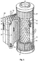
- a filter element is shown schematically, which is used, for example, in a hydraulic filter. Use in a hydraulic filter is particularly preferred. It is possible to use the filter element in other filters. It comprises a perforated frame or a cylindrical support tube 12 through which a plurality of flow openings 13 pass in the radial direction. In the circumferential direction, the support tube 12 is surrounded by a multilayer filter bellows 15, which in FIG Fig. 1 for clarity is partially shown in the manner of an exploded view.
- the filter bellows 15 can also be referred to as a corrugated or folded flat material.
- the filter bellows 15 is folded in a star shape by folds 17 running parallel to the longitudinal axis of the support tube 12 in such a way that fold tips 18 lying radially outside and bottoms 19 lying radially inside alternately follow one another along its circumference.
- the filter bellows 15 specifically has a three-layer filter material 22 with a fine filter layer in the form of a fleece 24, which is covered on the raw side by a pre-filter fleece 27 and on the clean side by a protective fleece 28 in the flow direction 26, i.e. in the illustrated embodiment in the radial direction from the outside to the inside .
- the fleeces can for example be made of a plastic or fiberglass material.
- the invention is not restricted to such a filter material, but is also suitable for other filter materials which are intended for filtration, for example with more or less than three layers.
- the filter material 22 is supported on the clean side on a support fabric 30, which lies flat against the protective fleece 28 of the filter material 22 and is also folded in a star shape.
- the support fabric 30 in turn is supported in the flow direction 26 in the area of the fold bases 19 on the support tube 12.
- a protective fabric 31 is arranged which lies flat against the pre-filter fleece 27 of the filter material 22 and is also folded in a star shape.
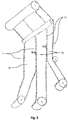
- the support fabric 30 and the protective fabric 31 are each made of a fabric layer according to the embodiment of the invention, which is based on Fig. 2 is explained in more detail. It is possible that only the support fabric 30 or only the protective fabric 31 are made from the fabric layer described in more detail below.
- the fabric layer according to the exemplary embodiment according to the invention has a first fabric strip 10.
- the first fabric strip 10 can also be referred to as the main fabric.
- the main fabric is characterized in that it enables the main function of the filter element, namely the flow through the filter material 22 required for the filtration.
- the first fabric strip 10 therefore has a particularly large effective area.
- the first fabric strip 10 extends in the longitudinal direction of the fabric layer according to FIG Fig. 2 . In the assembled state, ie in the filter element, the first fabric strip 10 extends in the circumferential direction of the filter element.
- first and second fabric strips 10, 11 can be provided.
- first fabric strips 10 and four second fabric strips 11 are provided, the first fabric strips 10 each extending between two second fabric strips 11.
- the entire fabric layer is cut so that partial fabric layers are created which each have a first fabric strip 10 and two second fabric strips 11 which extend along the edges of the fabric layer.
- the edges of the partial fabric layers form the front edges of the bellows 15, as in FIG Fig. 1 to see.
- three partial fabric layers are formed.
- the width of the partial fabric layers can differ. The width depends on the distance between the second fabric strips 11 from one another. This has the advantage that the fabric layer can be tailored for different filter bellows sizes.
- the main fabric that is to say the first fabric strip 10
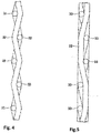
- the first fabric strip 10 is produced in the "twill weave” type of weave.
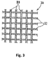
- the second fabric strips 11 are each produced in the type of weave "plain weave”.
- the first type of weave of the first fabric strip 10 can specifically have a twill weave or a herringbone twill weave. It is also possible that the first type of weave comprises a satin weave.
- the second type of weave can be plain weave or plain weave, as in Fig. 2 , or a leno weave. These second types of weave are characterized by the fact that they fix the warp threads well in the fabric layer (fixation weave).
- the fabric layer is not consistently woven in one and the same type of weave, for example in a twill weave, as in the prior art. Rather, at the points where the fabric layer is cut later, i. H. Woven on defined widths, each with a strip with a certain number of warp threads in a different type of weave, in particular in linen weave or linen weave.
- the main advantage is that the plain weave at the edge of the edge thread by the more frequent change, i. H. the more frequent cranking of the thread, is fixed much better in the fabric than with a pure twill weave. As a result, the edge thread tends to be much less likely to jump out of the fabric or to be pulled out.
- the filter element in addition to the fabric layer, is claimed with a filter bellows in which at least one fabric layer is integrated according to the exemplary embodiment according to the invention.
- the filter bellows contains several layers of material that are folded together to form a star-shaped pattern.
- One or two of these layers consist of a body tissue that has a positive effect on the performance data and, in particular, the pressure loss of the filter element.
- the first fabric strip 10 is designed in this way.
- Additional zones or strips with a plain weave can also be introduced between the actual cutting lanes, for example to create more flexible options after weaving to be able to cut to different tape widths.
- the plain weave on the edge ie in the second fabric strip
- other types of weave that differ from the actual first type of weave of the fabric can also be used on the edge, which hold the edge thread in the fabric much better than the twill weave.
- the leno weave comes into question here, for example. The manual reworking by jumping out of the edge threads is no longer necessary, which results in a significant improvement in production for the filter element production.
Abstract
Die Erfindung betrifft Gewebelage, insbesondere Schutzgewebe und/oder Stützgewebe, für ein gewelltes oder gefaltetes Flachmaterial eines Filterelements, wobei das Flachmaterial eine Vielzahl von parallel zueinander verlaufenden Falten (17) oder Wellen aufweist, die aufeinander folgende Falten- oder Wellenspitzen (18) und Falten- oder Wellentäler (19) bilden, die durch eine Faltenflanke miteinander verbunden sind, wobei das Flachmaterial von einem Fluid durchströmbar ist, wobei die Gewebelage einen ersten Gewebebereich, insbesondere einen ersten Gewebestreifen (10), und wenigstens einen zweiten Gewebebereich, insbesondere einen zweiten Gewebestreifen (11), umfasst, deren Fäden, insbesondere Schussfäden (32), ineinander übergehen, wobei der erste Gewebebereich, insbesondere der erste Gewebestreifen (10), eine erste Bindungsart und der zweite Gewebebereich, insbesondere der zweite Gewebestreifen (11), eine zweite Bindungsart aufweisen, die sich von der ersten Bindungsart unterscheidet.

Description
Die Erfindung betrifft eine Gewebelage für ein gewelltes oder gefaltetes Flachmaterial eines Filterelements mit den Merkmalen des Oberbegriffs des Anspruchs 1. Eine derartige Gewebelage ist beispielsweise aus
Mittels derartiger Flachmaterialien können einer Flüssigkeit Fremdstoffe, beispielsweise verunreinigende Partikel, entzogen werden, so dass der Gehalt an Fremdstoffen in der Flüssigkeit durch das Hindurchströmen durch das Flachmaterial reduziert werden kann. Um die wirksame Fläche des Flachmaterials zu erhöhen, wird dieses gefaltet oder gewellt. Dadurch wird die effektiv nutzbare Fläche erhöht, ohne dass die Außenabmessungen des Flachmaterials vergrößert werden müssen. Ein derartiges Flachmaterial wird auch Filterbalg genannt. Die Belastung des Flachmaterials durch das hindurchströmende Fluid kann zur Folge haben, dass sich die Falten oder Wellen auf der Abströmseite des Flachmaterials dicht aneinander legen. Dies erhöht den Durchflusswiderstand des Flachmaterials und damit den Druckverlust des Fluids beim Durchströmen des Flachmaterials. Bei dem bekannten Flachmaterial ist daher vorgesehen, dass die Gewebelage verformbar ist und eine Köperbindung aufweist. Dadurch wird die mechanische Belastbarkeit eines mit einer derartigen Gewebelage hergestellten, gewellten oder gefalteten Flachmaterials gesteigert und die Gefahr einer Beschädigung bei Druckwechselbelastungen verringert. Trotz der hohen mechanischen Belastbarkeit zeichnet sich das bekannte Flachmaterial durch einen geringen Durchflusswiderstand aufgrund der Köperbindung aus.By means of such flat materials, foreign substances, for example contaminating particles, can be removed from a liquid, so that the content of foreign substances in the liquid can be reduced by flowing through the flat material. In order to increase the effective area of the flat material, it is folded or corrugated. This increases the effectively usable area without having to increase the external dimensions of the flat material. Such a flat material is also called a filter bellows. The loading of the flat material by the fluid flowing through it can have the consequence that the folds or waves on the outflow side of the flat material lie close to one another. This increases the flow resistance of the flat material and thus the pressure loss of the fluid when flowing through the flat material. At the known flat material is therefore provided that the fabric layer is deformable and has a twill weave. This increases the mechanical strength of a corrugated or folded flat material produced with such a fabric layer and reduces the risk of damage in the event of alternating pressure loads. Despite the high mechanical strength, the known flat material is characterized by a low flow resistance due to the twill weave.
Bei der Verarbeitung der bekannten Gewebelage zu einem Flachmaterial kann es zu Nacharbeitsaufwand kommen, da sich die Fäden der Gewebelage während der Verarbeitung an bestimmten Stellen aus der Gewebelage lokal lösen können.When processing the known fabric layer into a flat material, reworking costs may arise, since the threads of the fabric layer can loosen locally from the fabric layer at certain points during processing.
Der Erfindung liegt die Aufgabe zugrunde, eine Gewebelage der eingangs genannten Art für ein gewelltes oder gefaltetes Flachmaterial eines Filterelements dahingehend zu verbessern, dass die Verarbeitung der Gewebelage vereinfacht wird. Der Erfindung liegt ferner die Aufgabe zugrunde, ein Flachmaterial, ein Filterelement, einen Filter und ein Verfahren zur Herstellung einer Gewebelage anzugeben.The invention is based on the object of improving a fabric layer of the type mentioned at the beginning for a corrugated or folded flat material of a filter element to the effect that the processing of the fabric layer is simplified. The invention is also based on the object of specifying a flat material, a filter element, a filter and a method for producing a fabric layer.
Erfindungsgemäß wird diese Aufgabe mit Blick auf die Gewebelage durch den Gegenstand des Anspruchs 1 gelöst. Die Aufgabe wird mit Blick auf das Flachmaterial durch den Gegenstand des Anspruchs 10, mit Blick auf das Filterelement durch den Gegenstand des Anspruchs 11, mit Blick auf den Filter durch den Gegenstand des Anspruchs 14 und mit Blick auf das Verfahren durch den Gegenstand des Anspruchs 15 gelöst.According to the invention, this object is achieved with a view to the fabric layer by the subject matter of claim 1. The object is achieved with regard to the flat material by the subject matter of
Konkret wird die Aufgabe durch eine Gewebelage für ein gewelltes oder gefaltetes Flachmaterial eines Filterelements gelöst, wobei das Flachmaterial eine Vielzahl von parallel zueinander verlaufenden Falten oder Wellen aufweist, die aufeinanderfolgende eine Falten- oder Wellenspitzen und Falten- oder Wellentäler bilden, die durch eine Faltenflanke miteinander verbunden sind. Das Flachmaterial ist von einem Fluid durchströmbar. Die Gewebelage umfasst einen ersten Gewebebereich, insbesondere einen ersten Gewebestreifen und wenigstens einen zweiten Gewebebereich, insbesondere einen zweiten Gewebestreifen. Die Fäden des ersten Gewebebereichs, insbesondere des ersten Gewebestreifens und des zweiten Gewebebereichs, insbesondere des zweiten Gewebestreifens, gehen ineinander über. Bei den Fäden handelt es sich insbesondere um Schussfäden. Der erste Gewebebereich, insbesondere der erste Gewebestreifen weist eine erste Bindungsart und der zweite Gewebebereich, insbesondere der zweite Gewebestreifen eine zweite Bindungsart auf. Die zweite Bindungsart unterscheidet sich von der ersten Bindungsart. Bei der erfindungsgemäßen Gewebelage kann es sich um ein Schutzgewebe und/oder Stützgewebe für ein gewelltes oder gefaltetes Flachmaterial eines Filterelements handeln.Specifically, the object is achieved by a fabric layer for a corrugated or folded flat material of a filter element, the flat material having a plurality of folds or waves running parallel to one another, which form successive folds or wave peaks and folds or wave troughs that are joined by a fold flank are connected. A fluid can flow through the flat material. The fabric layer comprises a first fabric area, in particular a first fabric strip and at least one second fabric area, in particular a second fabric strip. The threads of the first fabric area, in particular of the first fabric strip and of the second fabric area, in particular of the second fabric strip, run into each other. The threads are in particular weft threads. The first fabric area, in particular the first fabric strip, has a first type of weave and the second fabric area, in particular the second fabric strip, has a second type of weave. The second type of binding is different from the first type of binding. The fabric layer according to the invention can be a protective fabric and / or support fabric for a corrugated or folded flat material of a filter element.
Der erste Gewebebereich ist vorzugsweise ein erster Gewebestreifen, also ein längliches Gebilde, das sich bandförmig in der Gewebelage erstreckt. Dasselbe gilt für den zweiten Gewebebereich, der vorzugsweise einen zweiten Gewebestreifen bildet. Andere Geometrien sind möglich. Die Vorteile der Erfindung werden nachstehend anhand der Gewebestreifen beschrieben, gelten aber gleichermaßen für die allgemeinen Gewebebereiche.The first fabric area is preferably a first fabric strip, that is to say an elongated structure which extends in the form of a band in the fabric layer. The same applies to the second fabric area, which preferably forms a second fabric strip. Other geometries are possible. The advantages of the invention are described below with reference to the fabric strips, but apply equally to the general fabric areas.
Die Erfindung hat den Vorteil, dass lokal unterschiedliche Funktionen oder Eigenschaften der Gewebelage durch die Wahl der entsprechenden Bindungsart eingestellt werden können. Dies wird dadurch erreicht, dass im Übergang vom ersten auf den zweiten Gewebestreifen die Bindungsart der Gewebelage wechselt. Der Wechsel der Bindungsarten ermöglicht eine andere Funktion oder Eigenschaft im Bereich der ersten Bindungsart der Gewebelage als im Bereich der zweiten Bindungsart der Gewebelage, da sich die erste und zweite Bindungsart voneinander unterscheiden.The invention has the advantage that locally different functions or properties of the fabric layer can be set by choosing the appropriate type of weave. This is achieved in that the weave of the fabric layer changes in the transition from the first to the second fabric strip. The change in the types of weave enables a different function or property in the area of the first type of weave of the fabric layer than in the area of the second type of weave of the layer of fabric, since the first and second types of weave differ from one another.
Beispielsweise ist es möglich, in den bei der Verarbeitung der Gewebelage kritischen Bereichen eine von der ersten Bindungsart unterschiedliche zweite Bindungsart einzusetzen, die eine bessere Fixierung der Fäden in der Gewebelage als im Bereich der ersten Bindungsart ermöglicht. Dadurch wird die Verarbeitung der Gewebelage vereinfacht, da eine Nachbearbeitung des Flachmaterials zumindest hinsichtlich der Gewebelage entfällt.For example, it is possible to use a second type of weave that is different from the first type of weave in the areas that are critical in the processing of the fabric layer and that enables the threads to be fixed better in the layer of fabric than in the area of the first type of weave. This simplifies the processing of the fabric layer, since there is no post-processing of the flat material, at least with regard to the fabric layer.
Die Erfindung ist nicht auf die Vereinfachung der Verarbeitung eingeschränkt. Vielmehr erlaubt die Erfindung ganz allgemein die lokale Einstellung bestimmter Funktionen oder Eigenschaften der Gewebelage wodurch beispielsweise die Leistungsfähigkeit des Filterelements verbessert werden kann. Dies wird durch die unterschiedlichen Bindungsarten der Gewebelage erreicht.The invention is not limited to the simplification of processing. Rather, the invention generally allows certain functions or properties of the fabric layer to be set locally, whereby the performance of the filter element can be improved, for example. This is achieved through the different types of weave in the fabric layer.
Die Erfindung ist nicht auf zwei verschiedene Bindungsarten eingeschränkt. Es ist möglich, dass mehr als zwei, beispielsweise drei oder vier Bindungsarten eingesetzt werden, die sich jeweils von der ersten Bindungsart unterscheiden.The invention is not limited to two different types of binding. It is possible to use more than two, for example three or four types of weave, each of which differs from the first type of weave.
Bevorzugte Ausführungsformen der Erfindung sind in den Unteransprüchen angegeben.Preferred embodiments of the invention are specified in the subclaims.
Bei einer besonders bevorzugten Ausführungsform bildet der zweite Gewebestreifen eine Fixierbindung, die die Fäden, insbesondere die Kettfäden des ersten Gewebestreifens fixiert. Diese Ausführungsform ist besonders geeignet, die Verarbeitung der Gewebelage zu vereinfachen, weil durch die zweite Bindungsart die Fäden daran gehindert werden, sich aus der Gewebelage zu lösen. Gerade für die Fixierung der Randfäden der Gewebelage ist diese Ausführungsform besonders geeignet.In a particularly preferred embodiment, the second fabric strip forms a fixing bond that fixes the threads, in particular the warp threads, of the first fabric strip. This embodiment is particularly suitable for simplifying the processing of the fabric layer because the second type of weave prevents the threads from becoming detached from the fabric layer. This embodiment is particularly suitable for fixing the edge threads of the fabric layer.
Vorzugsweise umfasst die zweite Bindungsart des zweiten Gewebestreifens eine Leinenbindung (auch Leinwandbindung genannt) oder eine Dreherbindung. Es hat sich gezeigt, dass die Leinenbindung oder die Dreherbindung eine bessere Fixierung der Fäden, insbesondere der Kettfäden in der Gewebelage ermöglichen, als beispielsweise eine Köperbindung. Durch die Kombination der unterschiedlichen Bindungsarten werden die optimalen Eigenschaften der jeweiligen Bindungsart beibehalten und gezielt zur Verbesserung der Eigenschaften der Gewebelage eingesetzt.The second type of weave of the second fabric strip preferably comprises a plain weave (also called a plain weave) or a leno weave. It has been shown that the linen weave or the leno weave enable the threads, in particular the warp threads, to be fixed better in the fabric layer than, for example, a twill weave. By combining the different types of weave, the optimal properties of the respective type of weave are retained and used specifically to improve the properties of the fabric layer.
Bei einer weiteren bevorzugten Ausführungsform bildet der zweite Gewebestreifen den Rand, insbesondere den stirnseitigen Rand der Gewebelage. Weiter vorzugsweise bildet jeweils ein zweiter Gewebestreifen die beiden stirnseitigen Ränder der Gewebelage. Unter einem stirnseitigen Rand der Gewebelage wird derjenige Rand verstanden, der bei dem Flachmaterial, in das die Gewebelage integriert ist, in axialer Richtung des Filterelements stirnseitig, d. h. im Bereich der jeweiligen Endscheibe des Filterelements angeordnet ist. Mit anderen Worten bildet der stirnseitige Rand des im montierten Zustand zylindrischen Flachmaterials die Oberkante bzw. die Unterkante des Flachmaterials.In a further preferred embodiment, the second fabric strip forms the edge, in particular the front edge of the fabric layer. More preferably, a second fabric strip each forms the two frontal edges of the fabric layer. A front edge of the fabric layer is understood to mean that edge which, in the case of the flat material in which the fabric layer is integrated, is arranged at the end in the axial direction of the filter element, ie in the region of the respective end disk of the filter element. In other words, the front edge of the flat material, which is cylindrical in the assembled state, forms the upper edge or the lower edge of the flat material.
In diesem Bereich ist die Fixierung der Kettfäden relevant, sodass diese Ausführungsform die Verarbeitung der Gewebelage besonders vereinfacht.In this area, the fixing of the warp threads is relevant, so that this embodiment particularly simplifies the processing of the fabric layer.
Vorzugsweise sind mehrere zweite Gewebestreifen mit Abstand angeordnet, wobei ein erster Gewebestreifen zwischen zwei zweiten Gewebestreifen angeordnet ist. Diese Ausführungsform umfasst unterschiedliche Varianten. Beispielsweise können die beiden stirnseitigen Ränder der Gewebelage durch jeweils einen zweiten Gewebestreifen gebildet sein, wobei zwischen den beiden zweiten Gewebestreifen ein erster Gewebestreifen angeordnet ist. Diese Ausführungsform ist in erster Linie dazu vorgesehen, die Verarbeitung der Gewebelage zu vereinfachen. Es ist auch möglich, dass drei oder mehr zweite Gewebestreifen vorgesehen sind, zwischen denen jeweils ein erster Gewebestreifen angeordnet ist, um unterschiedliche Funktionsbereiche der Gewebelage zu bilden. Außerdem wird durch diese Ausführungsform ein Zwischenprodukt der Gewebelage geschützt, das durch entsprechenden Zuschnitt in das Endprodukt überführt wird, also bspw. eine Gewebelage mit zwei zweiten Gewebestreifen und einem ersten Gewebestreifen dazwischen.A plurality of second fabric strips are preferably arranged at a distance, with a first fabric strip being arranged between two second fabric strips. This embodiment includes different variants. For example, the two front edges of the fabric layer can each be formed by a second fabric strip, a first fabric strip being arranged between the two second fabric strips. This embodiment is primarily intended to simplify the processing of the fabric layer. It is also possible that three or more second fabric strips are provided, between each of which a first fabric strip is arranged in order to form different functional areas of the fabric layer. In addition, this embodiment protects an intermediate product of the fabric layer, which is converted into the end product by appropriate cutting, thus for example a fabric layer with two second fabric strips and a first fabric strip in between.
Der erste Gewebestreifen, insbesondere das Hauptgewebe, kann eine größere Fläche als der zweite Gewebestreifen aufweisen. Dadurch werden die Strömungseigenschaften des Flachmaterials hauptsächlich durch den ersten Gewebestreifen der Gewebelage bestimmt.The first fabric strip, in particular the main fabric, can have a larger area than the second fabric strip. As a result, the flow properties of the flat material are mainly determined by the first fabric strip of the fabric layer.
Der erste Gewebestreifen bildet in einer weiteren Ausführungsform im Gebrauch einen Durchströmungsbereich des gewellten oder gefalteten Flachmaterials, der von dem Fluid durchströmbar ist, wobei der Durchströmungsbereich einen Strömungswiderstand aufweist, der kleiner als der Strömungswiderstand des zweiten Gewebestreifens ist.In a further embodiment, the first fabric strip forms a flow area of the corrugated or folded flat material through which the fluid can flow, wherein the flow area has a flow resistance that is smaller than the flow resistance of the second fabric strip.
Bei besonders bevorzugten Ausführungsform umfasst die erste Bindungsart des ersten Gewebestreifens, insbesondere des Hauptgewebes, eine Köperbindung, insbesondere eine Wechselköperbindung, insbesondere eine Fischgratköperbindung, oder eine Atlasbindung. Die Köperbindung hat den Vorteil, dass die mechanische Belastbarkeit des mit einer derartigen Gewebelage hergestellten, gewellten oder gefalteten Flachmaterials gesteigert und die Gefahr einer Beschädigung bei Druckwechselbelastungen verringert wird. Außerdem weist das so gebildete Flachmaterial einen geringen Durchflusswiderstand auf.In a particularly preferred embodiment, the first type of weave of the first fabric strip, in particular the main fabric, comprises a twill weave, in particular an alternate twill weave, in particular a herringbone twill weave, or a satin weave. The twill weave has the advantage that the mechanical resilience of the corrugated or folded flat material produced with such a fabric layer increases and the risk damage in the event of pressure fluctuations is reduced. In addition, the flat material formed in this way has a low flow resistance.
Besonders bevorzugt ist die Kombination einer Köperbindung für den ersten Gewebestreifen und einer Leinwandbindung oder Dreherbindung für den zweiten Gewebestreifen. Die Erfindung ist nicht auf diese Kombination eingeschränkt, sondern erstreckt sich auch auf andere Kombinationen von Bindungsarten.The combination of a twill weave for the first fabric strip and a plain weave or leno weave for the second fabric strip is particularly preferred. The invention is not restricted to this combination, but also extends to other combinations of types of weave.
Der erste Gewebestreifen, insbesondere das Hauptgewebe, und/oder der zweite Gewebestreifen kann ein Hybridgewebe mit ersten und zweiten Fäden bilden, wobei die ersten Fäden, insbesondere die Kettfäden, aus Kunststoff und die zweiten Fäden, insbesondere die Schussfäden aus Metall gebildet sind. Dadurch wird die Lebensdauer des Flachmaterials verlängert.The first fabric strip, in particular the main fabric, and / or the second fabric strip can form a hybrid fabric with first and second threads, the first threads, in particular the warp threads, being made of plastic and the second threads, in particular the weft threads, being made of metal. This extends the life of the flat material.
Das beanspruchte Flachmaterial weist wenigstens eine erfindungsgemäße Gewebelage auf. Zu den Vorteilen eines solchen Flachmaterials wird auf die Ausführungen im Zusammenhang mit der Gewebelage verwiesen.The claimed flat material has at least one fabric layer according to the invention. Regarding the advantages of such a flat material, reference is made to the explanations in connection with the fabric layer.
Dasselbe gilt für das Filterelement mit einem derartigen Flachmaterial. Bei einer bevorzugten Ausführungsform des Filterelements weist das Flachmaterial eine hohlzylindrische Form auf und ist an wenigstens einer Stirnseite mit einer Endscheibe verbunden. Ein zweiter Gewebestreifen der Gewebelage ist von der Endscheibe zumindest teilweise bedeckt. Dadurch wird vorteilhafterweise erreicht, dass beispielsweise im Fall der Fixierung der Randfäden der zweite Gewebestreifen mit der zweiten Bindungsart kein Teil der wirksamen Oberfläche des Filterelements ist, also nicht von Fluid durchströmt wird.The same applies to the filter element with such a flat material. In a preferred embodiment of the filter element, the flat material has a hollow cylindrical shape and is connected to an end plate on at least one end face. A second fabric strip of the fabric layer is at least partially covered by the end disk. This advantageously ensures that, for example, in the case of fixing the edge threads, the second fabric strip with the second type of weave is not part of the effective surface of the filter element, that is, fluid does not flow through it.
Der zweite Gewebestreifen kann zumindest teilweise im Kleberbett der Endscheibe angeordnet werden und liegt somit in einem Bereich des Filterelements der nicht durchströmt wird. Der Nachteil des zweiten Gewebestreifens hinsichtlich des Durchstömungsverhaltens wirkt sich daher nicht auf den Druckverlust des Filterelementes aus.The second fabric strip can be arranged at least partially in the adhesive bed of the end disk and is therefore in a region of the filter element through which there is no flow. The disadvantage of the second fabric strip with regard to the flow behavior therefore does not affect the pressure loss of the filter element.
Der beanspruchte Filter weist ein erfindungsgemäßes Filterelement auf, d. h. ein Filterelement mit einem Flachmaterial, das eine erfindungsgemäße Gewebelage umfasst.The claimed filter has a filter element according to the invention, ie a filter element with a flat material which comprises a fabric layer according to the invention.
Bei dem erfindungsgemäßen Verfahren zur Herstellung einer Gewebelage für ein gewelltes oder gefaltetes Flachmaterial eines Filterelements werden ein erster Gewebestreifen und wenigstens ein zweiter Gewebestreifen gewebt, deren Fäden, insbesondere Schussfäden, ineinander übergehen. Dabei wird von einer ersten Bindungsart des ersten Gewebestreifens auf eine zweite Bindungsart des zweiten Gewebestreifens beim Weben gewechselt. Die zweite Bindungsart unterscheidet sich von der ersten Bindungsart.In the method according to the invention for producing a fabric layer for a corrugated or folded flat material of a filter element, a first fabric strip and at least one second fabric strip are woven, the threads of which, in particular weft threads, merge into one another. In this case, a change is made from a first type of weave of the first fabric strip to a second type of weave of the second fabric strip during weaving. The second type of binding is different from the first type of binding.
Bei einer vorteilhaften Ausführungsform des Verfahrens wird eine Funktionsschicht des Flachmaterials mit der erfindungsgemäßen Gewebelage verbunden.In an advantageous embodiment of the method, a functional layer of the flat material is connected to the fabric layer according to the invention.
Die Erfindung wird nachstehend anhand eines Ausführungsbeispiels mit weiteren Einzelheiten unter Bezug auf die beigefügten schematischen Zeichnungen näher erläutert.The invention is explained in more detail below using an exemplary embodiment with further details with reference to the accompanying schematic drawings.
In diesen zeigen:
- Fig. 1
- eine perspektivische Ansicht eines Filterelements mit teilweise geschnittenem Filterbalg bzw. gefaltetem Flachmaterial;
- Fig. 2
- eine perspektivische Ansicht einer Gewebelage nach einem erfindungsgemäßen Ausführungsbeispiel bei der Herstellung, die in den Filterbalg gemäß
Fig. 1 integriert ist; - Fig. 3
- einen Ausschnitt eines zweiten Gewebestreifens der Gewebelage nach
Fig. 2 , bei der die Bindungsart "Leinwandbindung" realisiert ist; - Fig. 4
- einen Schnitt des zweiten Gewebestreifens mit der Bindungsart "Leinwandbindung" gemäß
Fig. 2 und - Fig. 5
- einen Schnitt des ersten Gewebestreifens mit der Bindungsart "Köperbindung" gemäß
Fig. 2 .
- Fig. 1
- a perspective view of a filter element with a partially cut filter bellows or folded flat material;
- Fig. 2
- a perspective view of a fabric layer according to an embodiment of the invention in the production, which in the filter bellows according to
Fig. 1 is integrated; - Fig. 3
- a section of a second fabric strip according to the fabric layer
Fig. 2 , in which the weave type "plain weave" is implemented; - Fig. 4
- a section of the second fabric strip with the type of weave "plain weave" according to FIG
Fig. 2 and - Fig. 5
- a section of the first fabric strip with the type of weave "twill weave" according to FIG
Fig. 2 .
In
Der Filterbalg 15 weist konkret ein dreilagiges Filtermaterial 22 auf mit einer Feinfilterschicht in Form eines Vlieses 24, das in Durchströmrichtung 26, in der dargestellten Ausführungsform also in radialer Richtung von außen nach innen, rohseitig von einem Vorfiltervlies 27 und reinseitig von einem Schutzvlies 28 abgedeckt ist. Die Vliese können beispielsweise aus einem Kunststoff- oder Glasfasermaterial gefertigt sein. Die Erfindung ist nicht auf ein derartiges Filtermaterial eingeschränkt, sondern ist auch für andere Filtermaterialien geeignet, die zur Filtration vorgesehen sind, bspw. mit mehr oder weniger als drei Lagen.The filter bellows 15 specifically has a three-
In Durchströmrichtung 26 stützt sich das Filtermaterial 22 reinseitig an einem Stützgewebe 30 ab, welches flächig am Schutzvlies 28 des Filtermaterials 22 anliegt und ebenfalls sternförmig gefaltet ist. Das Stützgewebe 30 wiederum stützt sich in Durchströmrichtung 26 im Bereich der Faltengründe 19 am Stützrohr 12 ab. Rohseitig, d. h. radial außen ist ein Schutzgewebe 31 angeordnet, das flächig am Vorfiltervlies 27 des Filtermaterials 22 anliegt und ebenfalls sternförmig gefaltet ist. Das Stützgewebe 30 und das Schutzgewebe 31 sind jeweils aus einer Gewebelage nach dem erfindungsgemäßen Ausführungsbeispiel hergestellt, das anhand
In
Der erste Gewebestreifen 10 geht in einen zweiten Gewebestreifen 11 über, der sich im Wesentlichen parallel zum ersten Gewebestreifen 10 erstreckt. Es ist möglich, dass der zweite Gewebestreifen 11 einen Versatz von wenigstens einem Kettfaden, insbesondere von mehreren Kettfäden, aufweist. Alternativ ist ein Zick-Zack-förmiger Verlauf des zweiten Gewebestreifens 11 möglich. Konkret gehen die Schussfäden des ersten Gewebestreifen 10 in die Schussfäden des zweiten Gewebestreifen 11 über. Die beiden Gewebestreifen 10, 11 verwenden also dieselben Schussfäden und bilden somit eine einheitliche bzw. zusammenhängende Gewebelage, die sich zumindest im Herstellungszustand in ein und derselben Ebene erstreckt. Wenn die Gewebelage in das Flachmaterial bzw. den Filterbalg 15 integriert ist, bildet diese dieselbe sternförmige Kontur, wie das Filtermaterial 22. Das Flachmaterial und somit die Gewebelage ist gewellt bzw. gefaltet.The
Wie in
Wie in
Im Beispiel gemäß
Es ist auch möglich, eine einzige Gewebelage mit mehreren ersten Gewebestreifen 10 herzustellen, die durch zweite Gewebestreifen 11 getrennt sind, ähnlich wie die Gesamtgewebelage vor dem Zuschnitt, also das ungeschnittene Gewebe 3. Dadurch kann das Filterelement unterschiedliche Durchströmungsbereiche mit unterschiedlichen Eigenschaften aufweisen, die durch die geeignete Wahl der jeweiligen Bindungsart für die ersten und zweiten Gewebestreifen 10, 11 eingestellt werden.It is also possible to produce a single fabric layer with a plurality of first fabric strips 10, which are separated by second fabric strips 11, similar to the overall fabric layer before the cutting, i.e. the uncut fabric 3. As a result, the filter element can have different flow areas with different properties that pass through the appropriate choice of the respective type of weave for the first and second fabric strips 10, 11 can be set.
Bei dem Ausführungsbeispiel gemäß
Andere Kombinationen von Bindungsarten sind möglich. So kann die erste Bindungsart des ersten Gewebestreifen 10 konkret eine Wechselköperbindung oder eine Fischgratköperbindung aufweisen. Es ist auch möglich, dass die erste Bindungsart eine Atlasbindung umfasst. Die zweite Bindungsart kann eine Leinenbindung oder Leinwandbindung, wie in
Ein Beispiel für eine Leinwandbildung (zweite Bindungsart) ist in
Ein Beispiel für eine Köperbindung (erste Bindungsart) ist in
Kommen zwei Lagen der zum Einsatz kommenden Gewebelage mit Köperbindung im Bereich des ersten Gewebestreifen 10 bzw. in den Bereichen der ersten Gewebestreifen 10 durch Falten- oder Wellenbildung unmittelbar aneinander zur Anlage, so liegen in Abströmrichtung hervorstehende Faden- oder Filamentabschnitte, insbesondere einander zugewandte und sich kreuzende Kett-und Schusshebungen, aneinander an. Die Gesamtdicke der durch Falten- oder Wellenbildung aneinander liegenden Lagen des Gewebes mit Köperbindung ist höher als die Gesamtdicke der durch Falten- oder Wellenbildung aneinander anliegenden Lagen des Gewebes mit Leinwandbindung. Zwischen den durch Falten- oder Wellenbildung aneinander anliegenden Lagen des Gewebes mit Köperbindung bilden sich Mikrokanäle aus, die auch durch eine leichte Relativbewegung der beiden Lagen nicht beeinträchtigt werden, sondern ihre Ausgestaltung stabil beibehalten.If two layers of the fabric layer with twill weave used in the area of the
Durch die Kombination der unterschiedlichen Bindungsarten werden also lokal unterschiedliche Eigenschaften der Gewebelage eingestellt, die beispielsweise im Fall der Leinwandbindung an den Rändern der Gewebelage den Nacharbeitsaufwand bei der Herstellung der Filterelemente wesentlich verringern, weil die Randfäden im Gewebeverbund fixiert sind.By combining the different types of weave, locally different properties of the fabric layer are set, which, for example, in the case of a plain weave at the edges of the fabric layer, significantly reduce the reworking effort in the manufacture of the filter elements because the edge threads are fixed in the fabric composite.
Hinzu kommt, dass die Anordnung der zweiten Gewebestreifen 11 an den stirnseitigen Rändern der Gewebelage, wie in
Zusammengefasst ist die Gewebelage nicht durchgängig in ein und derselben Bindungsart gewebt, beispielsweise in Köperbindung, wie im Stand der Technik. Vielmehr ist an den Stellen, an denen die Gewebelage später zugeschnitten wird, d. h. auf definierten Bandbreiten, jeweils ein Streifen mit einer bestimmten Anzahl an Kettfäden in einer anderen Bindungsart, insbesondere in Leinenbindung bzw. Leinwandbindung gewebt. Der Hauptvorteil besteht darin, dass durch die Leinenbindung am Rand der Randfaden durch den häufigeren Wechsel, d. h. die häufigere Kröpfung des Fadens, sehr viel besser im Gewebe fixiert ist als bei einer reinen Köperbindung. Dadurch neigt der Randfaden sehr viel weniger dazu, aus dem Gewebe heraus zu springen oder herausgezogen zu werden.In summary, the fabric layer is not consistently woven in one and the same type of weave, for example in a twill weave, as in the prior art. Rather, at the points where the fabric layer is cut later, i. H. Woven on defined widths, each with a strip with a certain number of warp threads in a different type of weave, in particular in linen weave or linen weave. The main advantage is that the plain weave at the edge of the edge thread by the more frequent change, i. H. the more frequent cranking of the thread, is fixed much better in the fabric than with a pure twill weave. As a result, the edge thread tends to be much less likely to jump out of the fabric or to be pulled out.
Im Rahmen der Erfindung wird zusätzlich zur Gewebelage das Filterelement mit einem Filterbalg beansprucht, in den wenigstens eine Gewebelage nach dem erfindungsgemäßen Ausführungsbeispiel integriert ist. Konkret enthält der Filterbalg mehrere Material-Lagen, die miteinander gefaltet werden, um ein sternförmiges Muster zu bilden. Eine oder zwei dieser Lagen (an- oder abströmseitig) bestehen aus einem Körpergewebe, das sich auf die Leistungsdaten und im speziellen den Druckverlust des Filterelements positiv auswirkt. Konkret ist der erste Gewebestreifen 10 so ausgebildet. Der an sich bestehende Nachteil des bezüglich des Druckverlustes optimierten Gewebes besteht darin, dass die Randfäden in der Köperbindung wenig im Gewebe gebunden sind, sodass während des Faltprozesses und nachgeschalteten Verarbeitungsschritten, wie zum Beispiel dem Vereinzeln der Faltenbälge die Randfäden nicht ausreichend gut im Gewebeverbund gehalten werden, wodurch zusätzliche Nacharbeit entsteht.In the context of the invention, in addition to the fabric layer, the filter element is claimed with a filter bellows in which at least one fabric layer is integrated according to the exemplary embodiment according to the invention. Specifically, the filter bellows contains several layers of material that are folded together to form a star-shaped pattern. One or two of these layers (upstream or downstream) consist of a body tissue that has a positive effect on the performance data and, in particular, the pressure loss of the filter element. Specifically, the
Das für das Hauptgewebe verwendete Körpergewebe bzw. allgemein der erste Gewebestreifen mit der ersten Bindungsart wird dadurch ergänzt, dass an den Rändern bzw. dort, wo nach dem Weben auf kleinere Bandbreiten geschnitten wird, eine zweite Bindungsart eingesetzt wird, konkret die Leinwandbindung. Dabei wird die Anzahl der Kettfäden, die in die Leinwandbindung gewoben werden, idealerweise maximal so gewählt, dass dieser Teil des Gewebes im Kleberbett der Endscheiben des Filterelements verschwinden und damit die Leistungsdaten des Filterelements nicht beeinflussen.The body fabric used for the main fabric or generally the first fabric strip with the first type of weave is supplemented by using a second type of weave, specifically the plain weave, at the edges or where the weaving is cut to smaller widths. The number of warp threads that are woven into the plain weave is ideally chosen so that this part of the fabric in the The adhesive bed of the end plates of the filter element disappear and thus does not affect the performance data of the filter element.
Es können zusätzlich auch weitere Zonen bzw. Streifen mit Leinwandbindung zwischen den eigentlichen Schneidgassen eingebracht werden, um zum Beispiel nach dem Weben flexiblere Möglichkeiten zu schaffen, um auf unterschiedliche Bandbreiten zuschneiden zu können. Anstelle der Leinwandbindung am Rand, d. h. im zweiten Gewebestreifen, können am Rand auch andere von der eigentlichen ersten Bindungsart des Gewebes abweichende Bindungsarten infrage kommen, die den Randfaden deutlich besser im Gewebe halten als die Köperbindung. Hier kommt beispielsweise die Dreherbindung infrage. Die manuelle Nacharbeit durch Herausspringen der Randfäden entfällt, woraus eine signifikante Produktionsverbesserung für die Filterelementfertigung zu verzeichnen ist.Additional zones or strips with a plain weave can also be introduced between the actual cutting lanes, for example to create more flexible options after weaving to be able to cut to different tape widths. Instead of the plain weave on the edge, ie in the second fabric strip, other types of weave that differ from the actual first type of weave of the fabric can also be used on the edge, which hold the edge thread in the fabric much better than the twill weave. The leno weave comes into question here, for example. The manual reworking by jumping out of the edge threads is no longer necessary, which results in a significant improvement in production for the filter element production.
- 11
- MutterrolleMother role
- 22
- Rolle für ZuschnittRoll for cutting
- 33
- ungeschnittenes Gewebeuncut tissue
- 44th
- SchneidmesserCutting knife
- 1010
- erster Gewebestreifenfirst strip of fabric
- 1111
- zweiter Gewebestreifensecond strip of fabric
- 1212
- StützrohrSupport tube
- 1313
- DurchflussöffnungenFlow openings
- 1414th
- freifree
- 1515th
- FilterbalgFilter bellows
- 1616
- freifree
- 1717th
- Faltenwrinkles
- 1818th
- FaltenspitzenWrinkle tips
- 1919th
- FaltengründeWrinkle reasons
- 2020th
- freifree
- 2121st
- freifree
- 2222nd
- FiltermaterialFilter material
- 2323
- freifree
- 2424
- Vliesfleece
- 2525th
- freifree
- 2626th
- DurchströmrichtungFlow direction
- 2727
- VorfiltervliesPre-filter fleece
- 2828
- SchutzvliesProtective fleece
- 2929
- freifree
- 3030th
- StützgewebeSupport fabric
- 3131
- SchutzgewebeProtective fabric
- 3232
- SchussfadenWeft
- 3333
- KettfadenWarp thread
Claims (16)
dadurch gekennzeichnet, dass
die Gewebelage einen ersten Gewebebereich, insbesondere einen ersten Gewebestreifen (10), und wenigstens einen zweiten Gewebebereich, insbesondere einen zweiten Gewebestreifen (11), umfasst, deren Fäden, insbesondere Schussfäden (32), ineinander übergehen, wobei der erste Gewebebereich, insbesondere der erste Gewebestreifen (10), eine erste Bindungsart und der zweite Gewebebereich, insbesondere der zweite Gewebestreifen (11), eine zweite Bindungsart aufweisen, die sich von der ersten Bindungsart unterscheidet.Fabric layer, in particular protective fabric and / or supporting fabric, for a corrugated or folded flat material of a filter element, the flat material having a plurality of folds (17) or waves running parallel to one another, the successive fold or wave peaks (18) and fold or wave troughs (19), which are connected to one another by a fold flank, wherein the flat material can be flowed through by a fluid,
characterized in that
the fabric layer comprises a first fabric area, in particular a first fabric strip (10), and at least one second fabric area, in particular a second fabric strip (11), the threads of which, in particular weft threads (32), merge, the first fabric area, in particular the first Fabric strips (10), a first type of weave and the second fabric region, in particular the second fabric strip (11), have a second type of weave which differs from the first type of weave.
dadurch gekennzeichnet, dass
der zweite Gewebestreifen (11) eine Fixierbindung bildet, die die Fäden, insbesondere Kettfäden (33), des ersten Gewebestreifens (10) fixiert.Fabric layer according to claim 1
characterized in that
the second fabric strip (11) forms a fixing bond which fixes the threads, in particular warp threads (33), of the first fabric strip (10).
dadurch gekennzeichnet, dass
die zweite Bindungsart des zweiten Gewebestreifens (11) eine Leinenbindung oder eine Dreherbindung umfasst.Fabric layer according to claim 1 or 2
characterized in that
the second type of weave of the second fabric strip (11) comprises a plain weave or a leno weave.
dadurch gekennzeichnet, dass
der zweite Gewebestreifen (11) den Rand der Gewebelage, insbesondere den stirnseitigen Rand der Gewebelage bildet.Fabric layer according to one of the preceding claims
characterized in that
the second fabric strip (11) forms the edge of the fabric layer, in particular the front edge of the fabric layer.
dadurch gekennzeichnet, dass
mehrere zweite Gewebestreifen (11) mit Abstand angeordnet sind, wobei ein erster Gewebestreifen (10) zwischen zwei zweiten Gewebestreifen (11) angeordnet ist.Fabric layer according to one of the preceding claims
characterized in that
a plurality of second fabric strips (11) are arranged at a distance, a first fabric strip (10) being arranged between two second fabric strips (11).
dadurch gekennzeichnet, dass
der erste Gewebestreifen (10), insbesondere das Hauptgewebe, eine größere Fläche als der zweite Gewebestreifen (11) aufweist.Fabric layer according to one of the preceding claims
characterized in that
the first fabric strip (10), in particular the main fabric, has a larger area than the second fabric strip (11).
dadurch gekennzeichnet, dass
der erste Gewebestreifen (10), insbesondere das Hauptgewebe, im Gebrauch einen Durchströmungsbereich des gewellten oder gefalteten Flachmaterials bildet, der von dem Fluid durchströmbar ist, wobei der Durchströmungsbereich einen Strömungswiderstand aufweist, der kleiner als der Strömungswiderstand des zweiten Gewebestreifens (11) ist.Fabric layer according to one of the preceding claims
characterized in that
the first fabric strip (10), in particular the main fabric, forms a flow area of the corrugated or folded flat material through which the fluid can flow, the flow area having a flow resistance which is smaller than the flow resistance of the second fabric strip (11).
dadurch gekennzeichnet, dass
die erste Bindungsart des ersten Gewebestreifens (10), insbesondere des Hauptgewebes, eine Köperbindung, insbesondere Wechselköperbindung, insbesondere Fischgratköper, oder eine Atlasbindung umfasst.Fabric layer according to one of the preceding claims
characterized in that
the first type of weave of the first fabric strip (10), in particular of the main fabric, comprises a twill weave, in particular a twill weave, in particular herringbone twill, or a satin weave.
dadurch gekennzeichnet, dass
der erste Gewebestreifen (10), insbesondere das Hauptgewebe, und/oder der zweite Gewebestreifen (11) ein Hybridgewebe mit ersten und zweiten Fäden bildet/bilden, wobei die ersten Fäden, insbesondere Kettfäden (33), aus Kunststoff und die zweiten Fäden, insbesondere Schussfäden (32), aus Metall gebildet sind.Fabric layer according to one of the preceding claims
characterized in that
the first fabric strip (10), in particular the main fabric, and / or the second fabric strip (11) forms / form a hybrid fabric with first and second threads, the first threads, in particular warp threads (33), being made of plastic and the second threads, in particular Weft threads (32) are formed from metal.
dadurch gekennzeichnet, dass
die Funktionsschicht mit wenigstens einer Gewebelage verbunden ist, die einen ersten Gewebestreifen (10), insbesondere ein Hauptgewebe, und wenigstens einen zweiten Gewebestreifen (11) aufweist, deren Fäden, insbesondere Schussfäden (32), ineinander übergehen, wobei der erste Gewebestreifen (10) eine erste Bindungsart und der zweite Gewebestreifen (11) eine zweite Bindungsart aufweisen, die sich von der ersten Bindungsart unterscheidet.Flat material for a filter element, the flat material having a corrugated or folded shape with a plurality of folds (17) or waves running parallel to one another, which form successive fold or wave peaks (18) and fold or wave troughs (19), each of which are connected to one another by a fold flank, wherein a fluid can flow through the flat material and has at least one functional layer for removing or supplying foreign substances from or to the fluid,
characterized in that
the functional layer is connected to at least one fabric layer which has a first fabric strip (10), in particular a main fabric, and at least one second fabric strip (11), the threads of which, in particular weft threads (32), merge into one another, the first fabric strip (10) a first type of weave and the second fabric strip (11) have a second type of weave which is different from the first type of weave.
dadurch gekennzeichnet, dass
das Flachmaterial eine hohlzylindrische Form aufweist und an wenigstens einer Stirnseite mit einer Endscheibe verbunden ist, wobei ein zweiter Gewebestreifen (11) von der Endscheibe zumindest teilweise bedeckt ist.Filter element according to claim 11
characterized in that
the flat material has a hollow cylindrical shape and at least one end face is connected to an end disk, a second fabric strip (11) being at least partially covered by the end disk.
dadurch gekennzeichnet, dass
der zweite Gewebestreifen (11) zumindest teilweise im Kleberbett der Endscheibe angeordnet ist.Filter element according to claim 12
characterized in that
the second fabric strip (11) is at least partially arranged in the adhesive bed of the end disk.
Applications Claiming Priority (2)
| Application Number | Priority Date | Filing Date | Title |
|---|---|---|---|
| DE102019109617.0A DE102019109617B3 (en) | 2019-04-11 | 2019-04-11 | Fabric layer, flat material, filter element, filter and method for producing a fabric layer |
| DE202019102088.1U DE202019102088U1 (en) | 2019-04-11 | 2019-04-11 | Fabric layer, flat material, filter element and filter |
Publications (1)
| Publication Number | Publication Date |
|---|---|
| EP3721964A1 true EP3721964A1 (en) | 2020-10-14 |
Family
ID=72018365
Family Applications (1)
| Application Number | Title | Priority Date | Filing Date |
|---|---|---|---|
| EP19195274.6A Pending EP3721964A1 (en) | 2019-04-11 | 2019-09-04 | Fabric layer, flat material, filter element, filter and method for producing a fabric layer |
Country Status (3)
| Country | Link |
|---|---|
| US (2) | US11358075B2 (en) |
| EP (1) | EP3721964A1 (en) |
| CN (2) | CN111809288B (en) |
Families Citing this family (1)
| Publication number | Priority date | Publication date | Assignee | Title |
|---|---|---|---|---|
| US11358075B2 (en) * | 2019-04-11 | 2022-06-14 | Argo-Hytos Group Ag | Fabric layer, flat material, filter element, filter and method for the production of a fabric layer |
Citations (2)
| Publication number | Priority date | Publication date | Assignee | Title |
|---|---|---|---|---|
| WO2009026978A2 (en) | 2007-08-24 | 2009-03-05 | Fsp Fluid Systems Partners Holding Ag | Corrugated or folded flat material |
| DE102010025218A1 (en) * | 2010-06-23 | 2011-12-29 | Hydac Filtertechnik Gmbh | Filter material for fluids |
Family Cites Families (9)
| Publication number | Priority date | Publication date | Assignee | Title |
|---|---|---|---|---|
| US2365766A (en) * | 1939-04-10 | 1944-12-26 | Oscar H Levier | Oil filter |
| PL161586B1 (en) * | 1990-01-04 | 1993-07-30 | Inst Inzynierii Materialow Wlo | Strainer |
| US5713399A (en) * | 1997-02-07 | 1998-02-03 | Albany International Corp. | Ultrasonic seaming of abutting strips for paper machine clothing |
| US20140034580A1 (en) * | 2010-04-22 | 2014-02-06 | Kaydon Custom Filtration Corporation | Apparatus and method for removing contaminants from industrial fluid |
| EP3140442A4 (en) * | 2014-05-09 | 2018-01-24 | The North Face Apparel Corp. | Unitary woven fabric construct of multiple zones |
| DE102014117506A1 (en) * | 2014-11-28 | 2016-06-02 | Filta Co., Ltd | Filter medium with large pleat spacing |
| CN204509608U (en) | 2015-03-25 | 2015-07-29 | 浙江恒泰网业有限公司 | A kind of raised line filter net cloth |
| CN109440273A (en) * | 2018-11-28 | 2019-03-08 | 泰安三英新材料有限公司 | A kind of inorganic fibre fabric hot melt tree lace consolidation device and operating method |
| US11358075B2 (en) * | 2019-04-11 | 2022-06-14 | Argo-Hytos Group Ag | Fabric layer, flat material, filter element, filter and method for the production of a fabric layer |
-
2019
- 2019-08-23 US US16/549,366 patent/US11358075B2/en active Active
- 2019-09-04 EP EP19195274.6A patent/EP3721964A1/en active Pending
- 2019-10-09 CN CN201910955511.1A patent/CN111809288B/en active Active
- 2019-10-09 CN CN201921683701.4U patent/CN211284735U/en active Active
-
2022
- 2022-05-13 US US17/663,301 patent/US20220288509A1/en active Pending
Patent Citations (2)
| Publication number | Priority date | Publication date | Assignee | Title |
|---|---|---|---|---|
| WO2009026978A2 (en) | 2007-08-24 | 2009-03-05 | Fsp Fluid Systems Partners Holding Ag | Corrugated or folded flat material |
| DE102010025218A1 (en) * | 2010-06-23 | 2011-12-29 | Hydac Filtertechnik Gmbh | Filter material for fluids |
Also Published As
| Publication number | Publication date |
|---|---|
| CN111809288A (en) | 2020-10-23 |
| US20220288509A1 (en) | 2022-09-15 |
| US11358075B2 (en) | 2022-06-14 |
| CN211284735U (en) | 2020-08-18 |
| CN111809288B (en) | 2022-11-29 |
| US20200324228A1 (en) | 2020-10-15 |
Similar Documents
| Publication | Publication Date | Title |
|---|---|---|
| EP2180931B1 (en) | Corrugated or folded flat material | |
| EP0261488B1 (en) | Paper-making felt and process for making the same | |
| EP1525041A1 (en) | Filter element and method for the production thereof | |
| DE2126080B2 (en) | Tubular separator for filtering and separating water and solids from fuel | |
| DE3337517A1 (en) | FILTER ELEMENT AND METHOD FOR THE PRODUCTION THEREOF | |
| EP3721964A1 (en) | Fabric layer, flat material, filter element, filter and method for producing a fabric layer | |
| WO2017025223A1 (en) | Water separation element comprising a support piece | |
| DE102019109617B3 (en) | Fabric layer, flat material, filter element, filter and method for producing a fabric layer | |
| EP1418261B1 (en) | Woven wire fabric | |
| EP3698861A1 (en) | Filter device | |
| DE2209928A1 (en) | THREE-DIMENSIONAL FABRIC AND METHOD OF MANUFACTURING IT | |
| EP2945722B1 (en) | Filter medium | |
| EP3454970B1 (en) | Pleated filter with structuring element | |
| DE202019102088U1 (en) | Fabric layer, flat material, filter element and filter | |
| EP1712409A1 (en) | Fixation tape for cushion of a motor vehicle seat | |
| DE102017127057B4 (en) | Composite filter | |
| DE102017114964A1 (en) | Covering and manufacturing process for such a fabric | |
| EP3475481B1 (en) | Fabric for a machine for producing a fibrous web and method for producing such a fabric | |
| WO2003014447A1 (en) | Fabric belt for a corrugated board gluing machine | |
| WO2013068073A1 (en) | Filter surface element for forming a prefilter layer of a multilayer filter medium | |
| DE102020201449B3 (en) | Annular filter element for cleaning a fluid and method for manufacturing such a filter element | |
| DE4419104C2 (en) | Candle filter with helical elevation | |
| AT502437B1 (en) | FILTER ELEMENT | |
| EP3384789B1 (en) | Tape for manufacturing cigarettes or filters of cigarettes and a method of manufacture of said tape | |
| EP3192578A2 (en) | Filter unit for an extractor hood |
Legal Events
| Date | Code | Title | Description |
|---|---|---|---|
| PUAI | Public reference made under article 153(3) epc to a published international application that has entered the european phase |
Free format text: ORIGINAL CODE: 0009012 |
|
| STAA | Information on the status of an ep patent application or granted ep patent |
Free format text: STATUS: THE APPLICATION HAS BEEN PUBLISHED |
|
| AK | Designated contracting states |
Kind code of ref document: A1 Designated state(s): AL AT BE BG CH CY CZ DE DK EE ES FI FR GB GR HR HU IE IS IT LI LT LU LV MC MK MT NL NO PL PT RO RS SE SI SK SM TR |
|
| AX | Request for extension of the european patent |
Extension state: BA ME |
|
| STAA | Information on the status of an ep patent application or granted ep patent |
Free format text: STATUS: REQUEST FOR EXAMINATION WAS MADE |
|
| 17P | Request for examination filed |
Effective date: 20210312 |
|
| RBV | Designated contracting states (corrected) |
Designated state(s): AL AT BE BG CH CY CZ DE DK EE ES FI FR GB GR HR HU IE IS IT LI LT LU LV MC MK MT NL NO PL PT RO RS SE SI SK SM TR |
|
| RAP3 | Party data changed (applicant data changed or rights of an application transferred) |
Owner name: ARGO-HYTOS GROUP AG |
|
| STAA | Information on the status of an ep patent application or granted ep patent |
Free format text: STATUS: EXAMINATION IS IN PROGRESS |
|
| 17Q | First examination report despatched |
Effective date: 20220914 |
|
| P01 | Opt-out of the competence of the unified patent court (upc) registered |
Effective date: 20230613 |