EP3721846B1 - Automated systems for powered cots - Google Patents
Automated systems for powered cots Download PDFInfo
- Publication number
- EP3721846B1 EP3721846B1 EP20156768.2A EP20156768A EP3721846B1 EP 3721846 B1 EP3721846 B1 EP 3721846B1 EP 20156768 A EP20156768 A EP 20156768A EP 3721846 B1 EP3721846 B1 EP 3721846B1
- Authority
- EP
- European Patent Office
- Prior art keywords
- cot
- roll
- legs
- actuator
- support frame
- Prior art date
- Legal status (The legal status is an assumption and is not a legal conclusion. Google has not performed a legal analysis and makes no representation as to the accuracy of the status listed.)
- Active
Links
- 210000001364 upper extremity Anatomy 0.000 claims description 117
- 230000003213 activating effect Effects 0.000 claims description 13
- 238000005259 measurement Methods 0.000 claims description 10
- 238000000034 method Methods 0.000 description 15
- 230000000007 visual effect Effects 0.000 description 15
- 230000002596 correlated effect Effects 0.000 description 9
- 238000003825 pressing Methods 0.000 description 9
- 230000006835 compression Effects 0.000 description 8
- 238000007906 compression Methods 0.000 description 8
- 230000003287 optical effect Effects 0.000 description 8
- 241001071864 Lethrinus laticaudis Species 0.000 description 5
- 230000008901 benefit Effects 0.000 description 5
- 238000013461 design Methods 0.000 description 5
- 230000008569 process Effects 0.000 description 5
- 230000005355 Hall effect Effects 0.000 description 4
- 230000008859 change Effects 0.000 description 4
- 239000012530 fluid Substances 0.000 description 4
- 238000004891 communication Methods 0.000 description 2
- 230000008878 coupling Effects 0.000 description 2
- 238000010168 coupling process Methods 0.000 description 2
- 238000005859 coupling reaction Methods 0.000 description 2
- 230000001419 dependent effect Effects 0.000 description 2
- 230000009977 dual effect Effects 0.000 description 2
- 230000006870 function Effects 0.000 description 2
- 230000005484 gravity Effects 0.000 description 2
- 239000002184 metal Substances 0.000 description 2
- 238000005096 rolling process Methods 0.000 description 2
- 230000003068 static effect Effects 0.000 description 2
- 238000012546 transfer Methods 0.000 description 2
- 229920000049 Carbon (fiber) Polymers 0.000 description 1
- 241001465754 Metazoa Species 0.000 description 1
- 238000013459 approach Methods 0.000 description 1
- 239000004917 carbon fiber Substances 0.000 description 1
- 239000002131 composite material Substances 0.000 description 1
- 230000001276 controlling effect Effects 0.000 description 1
- 230000003247 decreasing effect Effects 0.000 description 1
- 238000001514 detection method Methods 0.000 description 1
- 238000006073 displacement reaction Methods 0.000 description 1
- 230000004907 flux Effects 0.000 description 1
- -1 for example Substances 0.000 description 1
- 230000010354 integration Effects 0.000 description 1
- 239000004973 liquid crystal related substance Substances 0.000 description 1
- 239000000463 material Substances 0.000 description 1
- 230000007246 mechanism Effects 0.000 description 1
- VNWKTOKETHGBQD-UHFFFAOYSA-N methane Chemical group C VNWKTOKETHGBQD-UHFFFAOYSA-N 0.000 description 1
- 238000012986 modification Methods 0.000 description 1
- 230000004048 modification Effects 0.000 description 1
- 239000002674 ointment Substances 0.000 description 1
- 238000002360 preparation method Methods 0.000 description 1
- 239000011347 resin Chemical group 0.000 description 1
- 229920005989 resin Chemical group 0.000 description 1
- 230000001360 synchronised effect Effects 0.000 description 1
Images


Classifications
-
- A—HUMAN NECESSITIES
- A61—MEDICAL OR VETERINARY SCIENCE; HYGIENE
- A61G—TRANSPORT, PERSONAL CONVEYANCES, OR ACCOMMODATION SPECIALLY ADAPTED FOR PATIENTS OR DISABLED PERSONS; OPERATING TABLES OR CHAIRS; CHAIRS FOR DENTISTRY; FUNERAL DEVICES
- A61G1/00—Stretchers
- A61G1/02—Stretchers with wheels
- A61G1/0237—Stretchers with wheels having at least one swivelling wheel, e.g. castors
-
- A—HUMAN NECESSITIES
- A61—MEDICAL OR VETERINARY SCIENCE; HYGIENE
- A61G—TRANSPORT, PERSONAL CONVEYANCES, OR ACCOMMODATION SPECIALLY ADAPTED FOR PATIENTS OR DISABLED PERSONS; OPERATING TABLES OR CHAIRS; CHAIRS FOR DENTISTRY; FUNERAL DEVICES
- A61G1/00—Stretchers
- A61G1/02—Stretchers with wheels
- A61G1/0206—Stretchers with wheels characterised by the number of supporting wheels if stretcher is extended
- A61G1/0212—2 pairs having wheels within a pair on the same position in longitudinal direction, e.g. on the same axis
-
- A—HUMAN NECESSITIES
- A61—MEDICAL OR VETERINARY SCIENCE; HYGIENE
- A61G—TRANSPORT, PERSONAL CONVEYANCES, OR ACCOMMODATION SPECIALLY ADAPTED FOR PATIENTS OR DISABLED PERSONS; OPERATING TABLES OR CHAIRS; CHAIRS FOR DENTISTRY; FUNERAL DEVICES
- A61G1/00—Stretchers
- A61G1/02—Stretchers with wheels
- A61G1/025—Stretchers with wheels having auxiliary wheels, e.g. wheels not touching the ground in extended position
- A61G1/0262—Stretchers with wheels having auxiliary wheels, e.g. wheels not touching the ground in extended position having loading wheels situated in the front during loading
-
- A—HUMAN NECESSITIES
- A61—MEDICAL OR VETERINARY SCIENCE; HYGIENE
- A61G—TRANSPORT, PERSONAL CONVEYANCES, OR ACCOMMODATION SPECIALLY ADAPTED FOR PATIENTS OR DISABLED PERSONS; OPERATING TABLES OR CHAIRS; CHAIRS FOR DENTISTRY; FUNERAL DEVICES
- A61G1/00—Stretchers
- A61G1/02—Stretchers with wheels
- A61G1/025—Stretchers with wheels having auxiliary wheels, e.g. wheels not touching the ground in extended position
- A61G1/0256—Stretchers with wheels having auxiliary wheels, e.g. wheels not touching the ground in extended position having wheels which support exclusively if stretcher is in low position, e.g. on the folded legs
-
- A—HUMAN NECESSITIES
- A61—MEDICAL OR VETERINARY SCIENCE; HYGIENE
- A61G—TRANSPORT, PERSONAL CONVEYANCES, OR ACCOMMODATION SPECIALLY ADAPTED FOR PATIENTS OR DISABLED PERSONS; OPERATING TABLES OR CHAIRS; CHAIRS FOR DENTISTRY; FUNERAL DEVICES
- A61G1/00—Stretchers
- A61G1/04—Parts, details or accessories, e.g. head-, foot-, or like rests specially adapted for stretchers
- A61G1/052—Struts, spars or legs
- A61G1/056—Swivelling legs
- A61G1/0562—Swivelling legs independently foldable, i.e. at least part of the leg folding movement is not simultaneous
-
- A—HUMAN NECESSITIES
- A61—MEDICAL OR VETERINARY SCIENCE; HYGIENE
- A61G—TRANSPORT, PERSONAL CONVEYANCES, OR ACCOMMODATION SPECIALLY ADAPTED FOR PATIENTS OR DISABLED PERSONS; OPERATING TABLES OR CHAIRS; CHAIRS FOR DENTISTRY; FUNERAL DEVICES
- A61G1/00—Stretchers
- A61G1/04—Parts, details or accessories, e.g. head-, foot-, or like rests specially adapted for stretchers
- A61G1/052—Struts, spars or legs
- A61G1/056—Swivelling legs
- A61G1/0565—Swivelling legs simultaneously folding, e.g. parallelogram structures
- A61G1/0567—Swivelling legs simultaneously folding, e.g. parallelogram structures folding in x-shape
-
- A—HUMAN NECESSITIES
- A61—MEDICAL OR VETERINARY SCIENCE; HYGIENE
- A61G—TRANSPORT, PERSONAL CONVEYANCES, OR ACCOMMODATION SPECIALLY ADAPTED FOR PATIENTS OR DISABLED PERSONS; OPERATING TABLES OR CHAIRS; CHAIRS FOR DENTISTRY; FUNERAL DEVICES
- A61G13/00—Operating tables; Auxiliary appliances therefor
- A61G13/02—Adjustable operating tables; Controls therefor
- A61G13/06—Adjustable operating tables; Controls therefor raising or lowering of the whole table surface
-
- A—HUMAN NECESSITIES
- A61—MEDICAL OR VETERINARY SCIENCE; HYGIENE
- A61G—TRANSPORT, PERSONAL CONVEYANCES, OR ACCOMMODATION SPECIALLY ADAPTED FOR PATIENTS OR DISABLED PERSONS; OPERATING TABLES OR CHAIRS; CHAIRS FOR DENTISTRY; FUNERAL DEVICES
- A61G2200/00—Information related to the kind of patient or his position
- A61G2200/10—Type of patient
- A61G2200/14—Children
-
- A—HUMAN NECESSITIES
- A61—MEDICAL OR VETERINARY SCIENCE; HYGIENE
- A61G—TRANSPORT, PERSONAL CONVEYANCES, OR ACCOMMODATION SPECIALLY ADAPTED FOR PATIENTS OR DISABLED PERSONS; OPERATING TABLES OR CHAIRS; CHAIRS FOR DENTISTRY; FUNERAL DEVICES
- A61G2200/00—Information related to the kind of patient or his position
- A61G2200/10—Type of patient
- A61G2200/16—Type of patient bariatric, e.g. heavy or obese
-
- A—HUMAN NECESSITIES
- A61—MEDICAL OR VETERINARY SCIENCE; HYGIENE
- A61G—TRANSPORT, PERSONAL CONVEYANCES, OR ACCOMMODATION SPECIALLY ADAPTED FOR PATIENTS OR DISABLED PERSONS; OPERATING TABLES OR CHAIRS; CHAIRS FOR DENTISTRY; FUNERAL DEVICES
- A61G2203/00—General characteristics of devices
- A61G2203/10—General characteristics of devices characterised by specific control means, e.g. for adjustment or steering
-
- A—HUMAN NECESSITIES
- A61—MEDICAL OR VETERINARY SCIENCE; HYGIENE
- A61G—TRANSPORT, PERSONAL CONVEYANCES, OR ACCOMMODATION SPECIALLY ADAPTED FOR PATIENTS OR DISABLED PERSONS; OPERATING TABLES OR CHAIRS; CHAIRS FOR DENTISTRY; FUNERAL DEVICES
- A61G2203/00—General characteristics of devices
- A61G2203/30—General characteristics of devices characterised by sensor means
- A61G2203/42—General characteristics of devices characterised by sensor means for inclination
-
- A—HUMAN NECESSITIES
- A61—MEDICAL OR VETERINARY SCIENCE; HYGIENE
- A61G—TRANSPORT, PERSONAL CONVEYANCES, OR ACCOMMODATION SPECIALLY ADAPTED FOR PATIENTS OR DISABLED PERSONS; OPERATING TABLES OR CHAIRS; CHAIRS FOR DENTISTRY; FUNERAL DEVICES
- A61G2203/00—General characteristics of devices
- A61G2203/70—General characteristics of devices with special adaptations, e.g. for safety or comfort
- A61G2203/72—General characteristics of devices with special adaptations, e.g. for safety or comfort for collision prevention
- A61G2203/726—General characteristics of devices with special adaptations, e.g. for safety or comfort for collision prevention for automatic deactivation, e.g. deactivation of actuators or motors
-
- A—HUMAN NECESSITIES
- A61—MEDICAL OR VETERINARY SCIENCE; HYGIENE
- A61G—TRANSPORT, PERSONAL CONVEYANCES, OR ACCOMMODATION SPECIALLY ADAPTED FOR PATIENTS OR DISABLED PERSONS; OPERATING TABLES OR CHAIRS; CHAIRS FOR DENTISTRY; FUNERAL DEVICES
- A61G2220/00—Adaptations of particular transporting means
- A61G2220/10—Aircrafts
-
- A—HUMAN NECESSITIES
- A61—MEDICAL OR VETERINARY SCIENCE; HYGIENE
- A61G—TRANSPORT, PERSONAL CONVEYANCES, OR ACCOMMODATION SPECIALLY ADAPTED FOR PATIENTS OR DISABLED PERSONS; OPERATING TABLES OR CHAIRS; CHAIRS FOR DENTISTRY; FUNERAL DEVICES
- A61G2220/00—Adaptations of particular transporting means
- A61G2220/14—Cars
-
- A—HUMAN NECESSITIES
- A61—MEDICAL OR VETERINARY SCIENCE; HYGIENE
- A61G—TRANSPORT, PERSONAL CONVEYANCES, OR ACCOMMODATION SPECIALLY ADAPTED FOR PATIENTS OR DISABLED PERSONS; OPERATING TABLES OR CHAIRS; CHAIRS FOR DENTISTRY; FUNERAL DEVICES
- A61G7/00—Beds specially adapted for nursing; Devices for lifting patients or disabled persons
- A61G7/002—Beds specially adapted for nursing; Devices for lifting patients or disabled persons having adjustable mattress frame
- A61G7/012—Beds specially adapted for nursing; Devices for lifting patients or disabled persons having adjustable mattress frame raising or lowering of the whole mattress frame
Definitions
- the present disclosure is generally related to automated systems, and is specifically directed to automated systems for powered cots.
- Such emergency cots may be designed to transport and load bariatric patients into an ambulance.
- the PROFlexX ® cot by Ferno-Washington, Inc. of Wilmington, Ohio U.S.A., is a manually actuated cot that may provide stability and support for loads of about 700 pounds (about 317.5 kg).
- the PROFlexX ® cot includes a patient support portion that is attached to a wheeled undercarriage.
- the wheeled under carriage includes an X-frame geometry that can be transitioned between nine selectable positions.
- One recognized advantage of such a cot design is that the X-frame provides minimal flex and a low center of gravity at all of the selectable positions.
- Another recognized advantage of such a cot design is that the selectable positions may provide better leverage for manually lifting and loading bariatric patients.
- the POWERFlexx+ Powered Cot includes a battery powered actuator that may provide sufficient power to lift loads of about 700 pounds (about 317.5 kg).
- One recognized advantage of such a cot design is that the cot may lift a bariatric patient up from a low position to a higher position, i.e., an operator may have reduced situations that require lifting the patient.
- a further variety is a multipurpose roll-in emergency cot having a patient support stretcher that is removably attached to a wheeled undercarriage or transporter.
- the patient support stretcher when removed for separate use from the transporter, may be shuttled around horizontally upon an included set of wheels.
- One recognized advantage of such a cot design is that the stretcher may be separately rolled into an emergency vehicle such as station wagons, vans, modular ambulances, aircrafts, or helicopters, where space and reducing weight is a premium.
- the foregoing multipurpose roll-in emergency cots have been generally adequate for their intended purposes, they have not been satisfactory in all aspects.
- the foregoing emergency cots are loaded into ambulances according to loading processes that require at least one operator to support the load of the cot for a portion of the respective loading process.
- the embodiments described herein are directed to automated systems for versatile multipurpose roll-in emergency cots which may provide improved management of the cot weight, improved balance, and/or easier loading at any cot height, while being rollable into various types of rescue vehicles, such as ambulances, vans, station wagons, aircrafts and helicopters.
- a method of automatically actuating a powered roll-in cot to load a patient into an emergency vehicle having a loading surface comprises supporting the patient on a powered roll-in cot, the cot comprising a support frame extending between a front end of the cot and a back end of the cot, wherein the front end comprises a pair of front load wheels configured to assist in loading the cot onto a loading surface; a pair of retractable and extendible front legs coupled to the support frame and comprising front wheels and intermediate load wheels; and a pair of retractable and extendible back legs coupled to the support frame and comprising back wheels.
- the cot further comprises a cot actuation system comprising a front actuator coupled to the support frame and configured to actuate the front legs and raise and/or lower the front end of the cot, and a back actuator coupled to the support frame and configured to actuate the back legs and raise and/or lower the back end of the cot; and a control system comprising a control box communicatively coupled to one or more processors communicatively coupled to the front actuator and the back actuator to control the front actuator and the back actuator to actuate the front legs and the back legs independently or simultaneously; wherein the control box comprises a component to command to raise and/or lower the roll-in cot, the control box detecting an input signal, and wherein the input signal is processed by the one or more processors to control the front actuator and/or the back actuator to raise, lower, retract or release the front legs or back legs depending on the position of the cot.
- a cot actuation system comprising a front actuator coupled to the support frame and configured to actuate the front legs and raise and
- the method further comprises raising the support frame via front actuator and back actuator to a position where the front load wheels are located at a height greater than the loading surface via the control system detecting an input signal requesting the support frame be raised and activating the cot actuation system; positioning the roll-in cot such that its front load wheels are over the loading surface; lowering the support frame until the front load wheels contact the loading surface via the control system detecting an input signal requesting the support frame be lowered and activating the cot actuation system; raising the front legs by actuating the front actuator via the control system when the control system detects a signal requesting the support frame be lowered and that the front load wheels are in contact with the loading surface; and after the front legs have been retracted, rolling the cot forward until the intermediate load wheels have been loaded onto the loading surface.
- the method further comprises retracting the back legs by actuating the back actuator via the control system detecting an input signal requesting that the back legs be raised and the control system detecting that the intermediate load wheels are above the loading surface; and rolling the cot forwards until the back wheels are on the loading surface.
- a method of automatically actuating a powered roll-in cot to unload a patient from an emergency vehicle having a loading surface comprises supporting the patient on a powered roll-in cot comprising a support frame extending between a front end of the cot and a back end of the cot, wherein the front end comprises a pair of front load wheels configured to assist in loading the cot onto a loading surface, a pair of retractable and extendible front legs coupled to the support frame and comprising front wheels and intermediate load wheels, and a pair of retractable and extendible back legs coupled to the support frame and comprising back wheels.
- the cot additionally comprises a cot actuation system comprising a front actuator coupled to the support frame and configured to actuate the front legs and raise and/or lower the front end of the cot, and a back actuator coupled to the support frame and configured to actuate the back legs and raise and/or lower the back end of the cot, and a control system.
- the control system comprises a control box communicatively coupled to one or more processors communicatively coupled to the front actuator and the back actuator to control the front actuator and the back actuator to actuate the front legs and the back legs independently or simultaneously.
- the control box comprises a component to command to raise and/or lower the roll-in cot, the control box detecting an input signal, and the input signal is processed by the one or more processors to control the front actuator and/or the back actuator to raise, lower, retract or release the front legs or back legs depending on the position of the cot.
- the method comprises positioning the cot such that the back wheels are released from the loading surface, and lowering the back legs relative to the support frame until the back legs contact the floor by activating the back actuator via the cot control system detecting an input signal requesting the back legs be extended and the control system detecting that the back wheels are off the loading surface.
- the method further comprises positioning the cot such that the front legs are clear of the loading surface, and lowering the front legs relative to the support frame until the front legs contact the floor by activating the front actuator via the control system detecting an input signal requesting the front legs be extended and the control system detecting that the front legs are clear of the loading surface.
- a roll-in cot comprising a support frame extending between a front end of the cot and a back end of the cot, wherein the front end comprises a pair of front load wheels configured to assist in loading the cot onto a loading surface, a pair of retractable and extendible front legs coupled to the support frame and comprising front wheels and intermediate load wheels, and a pair of retractable and extendible back legs coupled to the support frame and comprising back wheels.
- the cot additionally comprises a cot actuation system comprising a front actuator coupled to the support frame and configured to actuate the front legs and raise and/or lower the front end of the cot, and a back actuator coupled to the support frame and configured to actuate the back legs and raise and/or lower the back end of the cot.
- the cot further comprises one or more processors communicatively coupled to the front actuator and the back actuator to control the front actuator and the back actuator to actuate the front legs and the back legs independently or simultaneously depending on the position of the cot, and a control box communicatively coupled to one or more processors and comprising a component to command to raise and/or lower the roll-in cot.
- the one or more processors execute machine readable instructions to: raise the support frame via front actuator and back actuator to a position where the front load wheels are located at a height greater than the loading surface via the control system detecting an input signal requesting the support frame be raised and activating the cot actuation system; lower the support frame until the front load wheels contact the loading surface via the control system detecting an input signal requesting the support frame be lowered and activating the cot actuation system; raise the front legs by actuating the front actuator via the control system when the control system detects the presence of an input signal requesting the support frame be lowered and when the control system detects that the front load wheels are in contact with the loading surface; and retract the back legs by actuating the back actuator via the control system detecting an input signal requesting that the back legs be raised and the control system detecting that the intermediate load wheels are above the loading surface.
- a powered roll-in cot comprising: a support frame extending between a front end of the cot and a back end of the cot, wherein the front end comprises a pair of front load wheels configured to assist in loading the cot onto a loading surface, a pair of retractable and extendible front legs coupled to the support frame and comprising front wheels and intermediate load wheels, and a pair of retractable and extendible back legs coupled to the support frame and comprising back wheels.
- the cot additionally comprises a cot actuation system comprising a front actuator coupled to the support frame and configured to actuate the front legs and raise and/or lower the front end of the cot, and a back actuator coupled to the support frame and configured to actuate the back legs and raise and/or lower the back end of the cot.
- the cot further comprises one or more processors communicatively coupled to the front actuator and the back actuator to control the front actuator and the back actuator to actuate the front legs and the back legs independently or simultaneously depending on the position of the cot, and a control box communicatively coupled to one or more processors and comprising a component to command to raise and/or lower the roll-in cot.
- the one or more processors execute machine readable instructions to: lower the back legs relative to the support frame until the back legs contact the floor by activating the back actuator via the cot control system detecting an input signal requesting the back legs be extended and the control system detecting that the back wheels are off the loading surface; and lower the front legs relative to the support frame until the front legs contact the floor by activating the front actuator via the control system detecting an input signal requesting the front legs be extended and the control system detecting that the front legs are clear of the loading surface.
- a cot can include a support frame, a front leg, a back leg, a front actuator, a back actuator, and one of more processors.
- the support frame can extend between a front end of the cot and a back end of the cot.
- the front leg and the back leg can be slidingly coupled to the support frame.
- the front actuator can be coupled to the front leg.
- the front actuator can slide the front leg along the support frame to retract and extend the front leg.
- the back actuator can be coupled to the back leg.
- the back actuator can slide the back leg along the support frame to retract and extend the front leg.
- the one or more processors can be communicatively coupled to the front actuator and the back actuator.
- the one or more processors execute machine readable instructions to receive signals from one or more sensors indicative of the front end of the cot and the front leg.
- the one or more processors can actuate the back actuator to extend the back leg to raise the back end of the cot, when the front end of the cot is supported by a surface and the front leg is retracted a predetermined amount.
- the one or more sensors can include a front angular sensor that measures a front angle between the front leg and the support frame.
- the front angular sensor can communicate a front angle signal to the one or more processors such that the front angle signal is correlated to the front angle.
- the one or more processors can execute machine readable instructions to determine that the front leg is retracted the predetermined amount based at least in part upon the front angle.
- the front angular sensor can be a potentiometer rotary sensor or a hall effect rotary sensor.
- the one or more sensors can comprise a back angular sensor that measures a back angle between the back leg and the support frame.
- the back angular sensor can communicate a back angle signal to the one or more processors such that the back angle signal is correlated to the back angle.
- the back angular sensor can be a potentiometer rotary sensor or a hall effect rotary sensor.
- the one or more processors can execute machine readable instructions to determine a difference between the back angle and the front angle based at least in part upon the front angle signal and the back angle signal.
- the one or more processors can execute machine readable instructions to compare the difference between the back angle and the front angle to a predetermined angle delta.
- the back leg can be automatically extended, when the difference between the back angle and the front angle is greater than or equal to the predetermined angle delta.
- the one or more sensors can comprise a distance sensor that measures a distance indicative of a position of the front leg, the back leg, or both with respect to the support frame.
- the distance sensor can communicate a distance signal to the one or more processors such that the distance signal is correlated to the distance.
- the one or more sensors can comprise a distance sensor that measures a distance indicative of a position the front end of the cot with respect to the surface and communicates a distance signal to the one or more processors such that the distance signal is correlated to the distance.
- the distance sensor can be coupled to the support frame or the back actuator.
- the distance sensor can be an ultrasonic sensor, a touch sensor, or a proximity sensor.
- the cot can include a front actuator sensor and a back actuator sensor.
- the front actuator sensor can be communicatively coupled to the one or more processors.
- the front actuator sensor can measure force applied to the front actuator and can communicate a front actuator force signal correlated to the force applied to the front actuator.
- the back actuator sensor can be communicatively coupled to the one or more processors.
- the back actuator sensor can measure force applied to the back actuator and can communicates a back actuator force signal correlated to the force applied to the back actuator.
- the one or more processors can execute machine readable instructions to determine that the front actuator force signal is indicative of tension and the back actuator force signal is indicative of compression.
- the back leg can be automatically extended, when the front actuator force signal is indicative of tension and the back actuator force signal is indicative of compression.
- the one or more processors can execute machine readable instructions to abort actuation of the back actuator if a position of the back leg with respect to the back end of the cot fails to change for a predetermined amount of time after the back actuator is actuated.
- the cot can include a support frame, a front leg, a back leg, a middle portion and a line indicator.
- the support frame can extend between a front end of the cot and a back end of the cot.
- the front leg and the back leg can be slidingly coupled to the support frame.
- the front leg and the back leg can retract and extend to facilitate loading or unloading from a support surface.
- the middle portion can be disposed between the front end of the cot and the back end of the cot.
- the line indicator can be coupled to the cot.
- the line indicator can project an optical line indicative of the middle portion of the cot.
- the optical line can be projected beneath or adjacent to the middle portion of the cot to a point offset from a side of the cot.
- the line indicator can include a laser, a light emitting diode, or a projector.
- an intermediate load wheel can be coupled to the front leg between a proximal end and a distal end of the front leg.
- the intermediate load wheel can be substantially aligned with the optical line during loading or unloading.
- the intermediate load wheel can be a fulcrum during loading or unloading.
- the intermediate load wheel can be located at a center of balance of the cot during the loading or unloading.
- one or more processors can be communicatively coupled to the line indicator.
- the one or more processors execute machine readable instructions to receive signals from one or more sensors indicative of the front end of the cot.
- the one or more processors execute machine readable instructions to cause the line indicator to project the optical line, when the front end of the cot is above the support surface.
- the cot can include a back actuator and a back actuator sensor.
- the back actuator can be coupled to the back leg.
- the back actuator can slide the back leg along the support frame to retract and extend the front leg.
- the back actuator sensor can be communicatively coupled to the one or more processors.
- the back actuator sensor can measure force applied to the back actuator and can communicate a back actuator force signal correlated to the force applied to the back actuator.
- the one or more processors can execute machine readable instructions to determine that the back actuator force signal is indicative of tension.
- the optical line can be projected, when the back actuator force signal is indicative of tension.
- the one or more sensors can include a distance sensor that measures a distance indicative of a position the front end of the cot with respect to the support surface.
- the distance sensor can communicate a distance signal to the one or more processors such that the distance signal is correlated to the distance.
- the one or more processors execute machine readable instructions to determine that the front end of the cot is above the support surface, when the distance is within a definable range.
- the distance sensor can be coupled to the back actuator or aligned with the intermediate load wheel.
- the distance sensor can be an ultrasonic sensor, a touch sensor, or a proximity sensor.
- a cot can include a support frame, a front leg, a back leg, an actuator, a drive light, one or more processors, and one or more operator controls.
- the support frame can extend between a front end of the cot and a back end of the cot.
- the front leg and the back leg can be slidingly coupled to the support frame.
- the actuator can be coupled to the front leg or the back leg.
- the actuator can slide the front leg or the back leg along the support frame to actuate the support frame.
- the drive light can be coupled to the actuator.
- the one or more processors can be communicatively coupled to the drive light.
- the one or more operator controls can be communicatively coupled to the one or more processors.
- the one or more processors can execute machine readable instructions to automatically cause the drive light to illuminate, when an input is received from the one or more operator controls.
- the actuator can actuate the front leg, and the drive light can illuminate an area in front of the front end of the cot.
- the actuator can actuate the back leg, and the drive light can illuminate an area behind the back end of the cot.
- the roll-in cot 10 comprises a support frame 12 comprising a front end 17, and a back end 19.
- the front end 17 is synonymous with the loading end, i.e., the end of the roll-in cot 10 which is loaded first onto a loading surface.
- the back end 19 is the end of the roll-in cot 10 which is loaded last onto a loading surface.
- the phrase “head end” may be used interchangeably with the phrase “front end,” and the phrase “foot end” may be used interchangeably with the phrase “back end.”
- the phrases “front end” and “back end” are interchangeable.
- the term “patient” refers to any living thing or formerly living thing such as, for example, a human, an animal, a corpse and the like.
- the front end 17 and/or the back end 19 may be telescoping.
- the front end 17 may be extended and/or retracted (generally indicated in FIG. 2 by arrow 217).
- the back end 19 may be extended and/or retracted (generally indicated in FIG. 2 by arrow 219).
- the total length between the front end 17 and the back end 19 may be increased and/or decreased to accommodate various sized patients.
- the support frame 12 may comprise a pair of substantially parallel lateral side members 15 extending between the front end 17 and the back end 19.
- lateral side members 15 may be a pair of spaced metal tracks.
- the lateral side members 15 comprise an undercut portion that is engageable with an accessory clamp (not depicted). Such accessory clamps may be utilized to removably couple patient care accessories such as a pole for an IV drip to the undercut portion.
- the undercut portion may be provided along the entire length of the lateral side members to allow accessories to be removably clamped to many different locations on the roll-in cot 10.
- the roll-in cot 10 also comprises a pair of retractable and extendible front legs 20 coupled to the support frame 12, and a pair of retractable and extendible back legs 40 coupled to the support frame 12.
- the roll-in cot 10 may comprise any rigid material such as, for example, metal structures or composite structures.
- the support frame 12, the front legs 20, the back legs 40, or combinations thereof may comprise a carbon fiber and resin structure.
- the roll-in cot 10 may be raised to multiple heights by extending the front legs 20 and/or the back legs 40, or the roll-in cot 10 may be lowered to multiple heights by retracting the front legs 20 and/or the back legs 40.
- the front legs 20 and the back legs 40 may each be coupled to the lateral side members 15. As shown in FIGS. 4A-5E , the front legs 20 and the back legs 40 may cross each other, when viewing the cot from a side, specifically at respective locations where the front legs 20 and the back legs 40 are coupled to the support frame 12 (e.g., the lateral side members 15 ( FIGS. 1-3 )). As shown in the embodiment of FIG. 1 , the back legs 40 may be disposed inwardly of the front legs 20, i.e., the front legs 20 may be spaced further apart from one another than the back legs 40 are spaced from one another such that the back legs 40 are each located between the front legs 20. Additionally, the front legs 20 and the back legs 40 may comprise front wheels 26 and back wheels 46 which enable the roll-in cot 10 to roll.
- the front wheels 26 and back wheels 46 may be swivel caster wheels or swivel locked wheels. As the roll-in cot 10 is raised and/or lowered, the front wheels 26 and back wheels 46 may be synchronized to ensure that the plane of the lateral side members 15 of the roll-in cot 10 and the plane of the wheels 26, 46 are substantially parallel.
- the roll-in cot 10 may also comprise a cot actuation system comprising a front actuator 16 configured to move the front legs 20 and a back actuator 18 configured to move the back legs 40.
- the cot actuation system may comprise one unit (e.g., a centralized motor and pump) configured to control both the front actuator 16 and the back actuator 18.
- the cot actuation system may comprise one housing with one motor capable to drive the front actuator 16, the back actuator 18, or both utilizing valves, control logic and the like.
- the cot actuation system may comprise separate units configured to control the front actuator 16 and the back actuator 18 individually.
- the front actuator 16 and the back actuator 18 may each include separate housings with individual motors to drive each of the front actuator 16 and the back actuator 18.
- the front actuator 16 is coupled to the support frame 12 and configured to actuate the front legs 20 and raise and/or lower the front end 17 of the roll-in cot 10.
- the back actuator 18 is coupled to the support frame 12 and configured to actuate the back legs 40 and raise and/or lower the back end 19 of the roll-in cot 10.
- the roll-in cot 10 may be powered by any suitable power source.
- the roll-in cot 10 may comprise a battery capable of supplying a voltage of, such as, about 24 V nominal or about 32 V nominal for its power source.
- the front actuator 16 and the back actuator 18 are operable to actuate the front legs 20 and back legs 40, simultaneously or independently. As shown in FIGS. 4A-5E , simultaneous and/or independent actuation allows the roll-in cot 10 to be set to various heights.
- the actuators described herein may be capable of providing a dynamic force of about 350 pounds (about 158.8 kg) and a static force of about 500 pounds (about 226.8 kg).
- the front actuator 16 and the back actuator 18 may be operated by a centralized motor system or multiple independent motor systems.
- the front actuator 16 and the back actuator 18 comprise hydraulic actuators for actuating the roll-in cot 10.
- the front actuator 16 and the back actuator 18 are dual piggy back hydraulic actuators, i.e., the front actuator 16 and the back actuator 18 each forms a master-slave hydraulic circuit.
- the master-slave hydraulic circuit comprises four hydraulic cylinders with four extending rods that are piggy backed (i.e., mechanically coupled) to one another in pairs.
- the dual piggy back actuator comprises a first hydraulic cylinder with a first rod, a second hydraulic cylinder with a second rod, a third hydraulic cylinder with a third rod and a fourth hydraulic cylinder with a fourth rod.
- the master-salve hydraulic circuits described herein can include any even number of hydraulic cylinders.
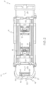
- the front actuator 16 and the back actuator 18 comprises a rigid support frame 180 that is substantially "H" shaped (i.e., two vertical portions connected by a cross portion).
- the rigid support frame 180 comprises a cross member 182 that is coupled to two vertical members 184 at about the middle of each of the two vertical members 184.
- a pump motor 160 and a fluid reservoir 162 are coupled to the cross member 182 and in fluid communication.
- the pump motor 160 and the fluid reservoir 162 are disposed on opposite sides of the cross member 182 (e.g., the fluid reservoir 162 disposed above the pump motor 160).
- the pump motor 160 may be a brushed bi-rotational electric motor with a peak output of about 1400 watts.
- the rigid support frame 180 may include additional cross members or a backing plate to provide further rigidity and resist twisting or lateral motion of the vertical members 184 with respect to the cross member 182 during actuation.
- Each vertical member 184 comprises a pair of piggy backed hydraulic cylinders (i.e., a first hydraulic cylinder and a second hydraulic cylinder or a third hydraulic cylinder and a fourth hydraulic cylinder) wherein the first cylinder extends a rod in a first direction and the second cylinder extends a rod in a substantially opposite direction.
- one of the vertical members 184 comprises an upper master cylinder 168 and a lower master cylinder 268.
- the other of the vertical members 184 comprises an upper slave cylinder 169 and a lower slave cylinder 269.
- master cylinders 168, 268 are piggy backed together and extend rods 165, 265 in substantially opposite directions, master cylinders 168, 268 may be located in alternate vertical members 184 and/or extend rods 165, 265 in substantially the same direction.
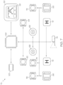
- control box 50 is communicatively coupled (generally indicated by the arrowed lines) to one or more processors 100.
- processors 100 can be any device capable of executing machine readable instructions such as, for example, a controller, an integrated circuit, a microchip, or the like.
- communicatively coupled means that the components are capable of exchanging data signals with one another such as, for example, electrical signals via conductive medium, electromagnetic signals via air, optical signals via optical waveguides, and the like.
- the one or more processors 100 can be communicatively coupled to one or more memory modules 102, which can be any device capable of storing machine readable instructions.
- the one or more memory modules 102 can include any type of memory such as, for example, read only memory (ROM), random access memory (RAM), secondary memory (e.g., hard drive), or combinations thereof.
- ROM read only memory
- RAM random access memory
- EEPROM electrically erasable programmable read-only memory
- EAROM electrically alterable read-only memory
- flash memory or combinations thereof.
- Suitable examples of RAM include, but are not limited to, static RAM (SRAM) or dynamic RAM (DRAM).
- the embodiments described herein can perform methods automatically by executing machine readable instructions with the one or more processors 100.
- the machine readable instructions can comprise logic or algorithm(s) written in any programming language of any generation (e.g., 1GL, 2GL, 3GL, 4GL, or 5GL) such as, for example, machine language that may be directly executed by the processor, or assembly language, object-oriented programming (OOP), scripting languages, microcode, etc., that may be compiled or assembled into machine readable instructions and stored.
- the machine readable instructions may be written in a hardware description language (HDL), such as logic implemented via either a field-programmable gate array (FPGA) configuration or an application-specific integrated circuit (ASIC), or their equivalents.
- HDL hardware description language
- FPGA field-programmable gate array
- ASIC application-specific integrated circuit
- a front actuator sensor 62 and a back actuator sensor 64 configured to detect whether the front and back actuators 16, 18 respectively are under tension or compression can be communicatively coupled to the one or more processors 100.
- tension means that a pulling force is being detected by the sensor. Such a pulling force is generally associated with the load being removed from the legs coupled to the actuator, i.e., the leg and or wheels are being suspended from the support frame 12 without making contact with a surface beneath the support frame 12.
- compression means that a pushing force is being detected by the sensor. Such a pushing force is generally associated with a load being applied to the legs coupled to the actuator, i.e., the leg and or wheels are in contact with a surface beneath the support frame 12 and transfer a compressive strain on the coupled actuator.
- the front actuator sensor 62 and the back actuator sensor 64 are coupled to the support frame 12; however, other locations or configurations are contemplated herein.
- the sensors may be proximity sensors, strain gauges, load cells, hall-effect sensors, or any other suitable sensor operable to detect when the front actuator 16 and/or back actuator 18 are under tension or compression.
- the front actuator sensor 62 and the back actuator sensor 64 may be operable to detect the weight of a patient disposed on the roll-in cot 10 (e.g., when strain gauges are utilized).
- the term "sensor,” as used herein, means a device that measures a physical quantity and converts it into a signal which is correlated to the measured value of the physical quantity.
- the term “signal” means an electrical, magnetic or optical waveform, such as current, voltage, flux, DC, AC, sinusoidal-wave, triangular-wave, square-wave, and the like, capable of being transmitted from one location to another.
- the roll-in cot 10 can comprise a front angular sensor 66 and a back angular sensor 68 that are communicatively coupled to the one or more processors 100.
- the front angular sensor 66 and the back angular sensor 68 can be any sensor that measures actual angle or change in angle such as, for example, a potentiometer rotary sensor, hall effect rotary sensor and the like.
- the front angular sensor 66 can be operable to detect a front angle ⁇ f of a pivotingly coupled portion of the front legs 20.
- the back angular sensor 68 can be operable to detect a back angle ⁇ b of a pivotingly coupled portion of the back legs 40.
- front angular sensor 66 and back angular sensor 68 are operably coupled to the front legs 20 and the back legs 40, respectively. Accordingly, the one or more processors 100 can execute machine readable instructions to determine the difference between the back angle ⁇ b and the front angle ⁇ f (angle delta).
- a loading state angle may be set to an angle such as about 20° or any other angle that generally indicates that the roll-in cot 10 is in a loading state (indicative of loading and/or unloading). Thus, when the angle delta exceeds the loading state angle the roll-in cot 10 may detect that it is in a loading state and perform certain actions dependent upon being in the loading state.
- distance sensors can be utilized to perform measurements analogous to angular measurements that determine the front angle ⁇ f and back angle ⁇ b .
- the angle can be determined from the positioning of the front legs 20 and/or the back legs 40 and relative to the lateral side members 15.
- the distance between the front legs 20 and a reference point along the lateral side members 15 can be measured.
- the distance between the back legs 40 and a reference point along the lateral side members 15 can be measured.
- the distance that the front actuator 16 and the back actuator 18 are extended can be measured. Accordingly, any of the distance measurements or angular measurements described herein can be utilized interchangeably to determine the positioning of the components of the roll-in cot 10.
- distance sensors may be coupled to any portion of the roll-in cot 10 such that the distance between a lower surface and components such as, for example, the front end 17, the back end 19, the front load wheels 70, the front wheels 26, the intermediate load wheels 30, the back wheels 46, the front actuator 16 or the back actuator 18 may be determined
- the front end 17 may comprise a pair of front load wheels 70 configured to assist in loading the roll-in cot 10 onto a loading surface (e.g., the floor of an ambulance).
- the roll-in cot 10 may comprise a load end sensor 76 communicatively coupled to the one or more processors 100.
- the load end sensor 76 is a distance sensor operable to detect the location of the front load wheels 70 with respect to a loading surface (e.g., distance from the detected surface to the front load wheels 70). Suitable distance sensors include, but are not limited to, ultrasonic sensors, touch sensors, proximity sensors, or any other sensor capable to detecting distance to an object.
- load end sensor 76 is operable to detect directly or indirectly the distance from the front load wheels 70 to a surface substantially directly beneath the front load wheels 70. Specifically, load end sensor 76 can provide an indication when a surface is within a definable range of distance from the front load wheels 70 (e.g., when a surface is greater than a first distance but less than a second distance). Accordingly, the definable range may be set such that a positive indication is provided by load end sensor 76 when the front load wheels 70 of the roll-in cot 10 are in contact with a loading surface. Ensuring that both front load wheels 70 are on the loading surface may be important, especially in circumstances when the roll-in cot 10 is loaded into an ambulance at an incline.
- the front legs 20 may comprise intermediate load wheels 30 attached to the front legs 20.
- the intermediate load wheels 30 may be disposed on the front legs 20 adjacent the front cross beam 22 ( FIG. 1 ).
- the roll-in cot 10 may comprise an intermediate load sensor 77 communicatively coupled to the one or more processors 100.
- the intermediate load sensor 77 is a distance sensor operable to detect the distance between the intermediate load wheels 30 and the loading surface 500. In one embodiment, when the intermediate load wheels 30 are within a set distance of the loading surface, the intermediate load sensor 77 may provide a signal to the one or more processors 100.
- intermediate load wheels 30 may also be disposed on the back legs 40 or any other position on the roll-in cot 10 such that the intermediate load wheels 30 cooperate with the front load wheels 70 to facilitate loading and/or unloading (e.g., the support frame 12).
- intermediate load wheels can be provided at any location that is likely to be a fulcrum or center of balance during the loading and/or unloading process described herein.
- the roll-in cot 10 may comprise a back actuator sensor 78 communicatively coupled to the one or more processors 100.
- the back actuator sensor 78 is a distance sensor operable to detect the distance between the back actuator 18 and the loading surface.
- back actuator sensor 78 is operable to detect directly or indirectly the distance from the back actuator 18 to a surface substantially directly beneath the back actuator 18, when the back legs 40 are substantially fully retracted ( FIGS. 4 , 5D, and 5E ).
- back actuator sensor 78 can provide an indication when a surface is within a definable range of distance from the back actuator 18 (e.g., when a surface is greater than a first distance but less than a second distance).
- the roll-in cot 10 may comprise a front drive light 86 communicatively coupled to the one or more processors 100.
- the front drive light 86 can be coupled to the front actuator 16 and configured to articulate with the front actuator 16. Accordingly, the front drive light 86 can illuminate an area directly in front of the front end 17 of the roll-in cot 10, as the roll-in cot 10 is rolled with the front actuator 16 extended, retracted, or any position there between.
- the roll-in cot 10 may also comprise a back drive light 88 communicatively coupled to the one or more processors 100.
- the back drive light 88 can be coupled to the back actuator 18 and configured to articulate with the back actuator 18.
- the back drive light 88 can illuminate an area directly in behind of the back end 19 of the roll-in cot 10, as the roll-in cot 10 is rolled with the back actuator 18 extended, retracted, or any position there between.
- the one or more processors 100 can receive input from any of the operator controls described herein and cause the front drive light 86, the back drive light 88, or both to be activated.
- the roll-in cot 10 may comprise a line indicator 74 communicatively coupled to the one or more processors 100.
- the line indicator 74 can be any light source configured to project a linear indication upon a surface such as, for example, a laser, light emitting diodes, a projector, or the like.
- the line indicator 74 can be coupled to the roll-in cot 10 and configured to project a line upon a surface below the roll-in cot 10, such that the line is aligned with the intermediate load wheels 30.
- the line can run from a point beneath or adjacent to the roll-in cot 10 and to a point offset from the side of the roll-in cot 10.
- an operator at the back end 19 of the can maintain visual contact with the line and utilize the line as a reference of the location of the center of balance of the roll-in cot 10 (e.g., the intermediate load wheels 30) during loading, unloading, or both.
- the back end 19 may comprise operator controls for the roll-in cot 10.
- the operator controls comprise the input components that receive commands from the operator and the output components that provide indications to the operator. Accordingly, the operator can utilize the operator controls in the loading and unloading of the roll-in cot 10 by controlling the movement of the front legs 20, the back legs 40, and the support frame 12.
- the operator controls may include a control box 50 disposed on the back end 19 of the roll-in cot 10.
- the control box 50 can be communicatively coupled to the one or more processors 100, which is in turn communicatively coupled to the front actuator 16 and the back actuator 18.
- the control box 50 can comprise a visual display component 58 such as, for example, a liquid crystal display, a touch screen and the like.
- control box 50 can receive input, which can be processed by the one or more processors 100 to control the front actuator 16 and back actuator 18.
- the embodiments described herein can include operator controls that are configured to directly control front actuator 16 and back actuator 18. That is, the automated processes described herein can be overridden by a user and the front actuator 16 and back actuator 18 can be actuated independent of input from the sensors.
- the operator controls may comprise one or more hand controls 57 (for example, buttons on telescoping handles) disposed on the back end 19 of the roll-in cot 10.
- the control box 50 may also include a component which may be used to raise and lower the roll-in cot 10.
- the component is a toggle switch 52, which is able to raise (+) or lower (-) the cot.
- Other buttons, switches, or knobs are also suitable. Due to the integration of the sensors in the roll-in cot 10, as is explained in greater detail herein, the toggle switch 52 may be used to control the front legs 20 or back legs 40 which are operable to be raised, lowered, retracted or released depending on the position of the roll-in cot 10.
- the toggle switch is analog (i.e., the pressure and/or displacement of the analog switch is proportional to the speed of actuation).
- the operator controls may comprise a visual display component 58 configured to inform an operator whether the front and back actuators 16, 18 are activated or deactivated, and thereby may be raised, lowered, retracted or released. While the operator controls are disposed at the back end 19 of the roll-in cot 10 in the present embodiments, it is further contemplated that the operator controls be positioned at alternative positions on the support frame 12, for example, on the front end 17 or the sides of the support frame 12. In still further embodiments, the operator controls may be located in a removably attachable wireless remote control that may control the roll-in cot 10 without physical attachment to the roll-in cot 10.
- front actuator sensor 62 and back actuator sensor 64 detect that the front actuator 16 and the back actuator 18 are under compression, i.e., the front legs 20 and the back legs 40 are in contact with a lower surface and are loaded.
- the front and back actuators 16 and 18 are both active when the front and back actuator sensors 62, 64 detect both the front and back actuators 16, 18, respectively, are under compression and can be raised or lowered by the operator using the operator controls (e.g., "-" to lower and "+” to raise).
- the roll-in cot 10 comprises a support frame 12 slidingly engaged with a pair of front legs 20 and a pair of back legs 40.
- Each of the front legs 20 are rotatably coupled to a front hinge member 24 that is rotatably coupled to the support frame 12.
- Each of the back legs 40 are rotatably coupled to a back hinge member 44 that is rotatably coupled to the support frame 12.
- the front hinge members 24 are rotatably coupled towards the front end 17 of the support frame 12 and the back hinge members 44 that are rotatably coupled to the support frame 12 towards the back end 19.
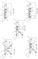
- FIG. 4A depicts the roll-in cot 10 in a lowest transport position. Specifically, the back wheels 46 and the front wheels 26 are in contact with a surface, the front leg 20 is slidingly engaged with the support frame 12 such that the front leg 20 contacts a portion of the support frame 12 towards the back end 19 and the back leg 40 is slidingly engaged with the support frame 12 such that the back leg 40 contacts a portion of the support frame 12 towards the front end 17.
- FIG. 4B depicts the roll-in cot 10 in an intermediate transport position, i.e., the front legs 20 and the back legs 40 are in intermediate transport positions along the support frame 12.
- FIG. 4C depicts the roll-in cot 10 in a highest transport position, i.e., the front legs 20 and the back legs 40 positioned along the support frame 12 such that the front load wheels 70 are at a maximum desired height which can be set to height sufficient to load the cot, as is described in greater detail herein.
- the embodiments described herein may be utilized to lift a patient from a position below a vehicle in preparation for loading a patient into the vehicle (e.g., from the ground to above a loading surface of an ambulance).
- the roll-in cot 10 may be raised from the lowest transport position ( FIG. 4A ) to an intermediate transport position ( FIG. 4B ) or the highest transport position ( FIG. 4C ) by simultaneously actuating the front legs 20 and back legs 40 and causing them to slide along the support frame 12.
- the actuation causes the front legs to slide towards the front end 17 and to rotate about the front hinge members 24, and the back legs 40 to slide towards the back end 19 and to rotate about the back hinge members 44.
- a user may interact with a control box 50 ( FIG.
- the roll-in cot 10 is raised from its current position (e.g., lowest transport position or an intermediate transport position) until it reaches the highest transport position. Upon reaching the highest transport position, the actuation may cease automatically, i.e., to raise the roll-in cot 10 higher additional input is required. Input may be provided to the roll-in cot 10 and/or control box 50 in any manner such as electronically, audibly or manually.
- the roll-in cot 10 may be lowered from an intermediate transport position ( FIG. 4B ) or the highest transport position ( FIG. 4C ) to the lowest transport position ( FIG. 4A ) by simultaneously actuating the front legs 20 and back legs 40 and causing them to slide along the support frame 12. Specifically, when being lowered, the actuation causes the front legs to slide towards the back end 19 and to rotate about the front hinge members 24, and the back legs 40 to slide towards the front end 17 and to rotate about the back hinge members 44.
- a user may provide input indicative of a desire to lower the roll-in cot 10 (e.g., by pressing a "-"on toggle switch 52).
- the roll-in cot 10 Upon receiving the input, the roll-in cot 10 lowers from its current position (e.g., highest transport position or an intermediate transport position) until it reaches the lowest transport position. Once the roll-in cot 10 reaches its lowest height (e.g., the lowest transport position) the actuation may cease automatically.
- the control box 50 provides a visual indication that the front legs 20 and back legs 40 are active during movement.
- the front legs 20 are in contact with the support frame 12 at a front-loading index 221 and the back legs 40 are in contact with the support frame 12 a back-loading index 241. While the front-loading index 221 and the back-loading index 241 are depicted in FIG. 4C as being located near the middle of the support frame 12, additional embodiments are contemplated with the front-loading index 221 and the back-loading index 241 located at any position along the support frame 12. Some embodiments can have a load position that is higher than the highest transport position.
- the highest load position may be set by actuating the roll-in cot 10 to the desired height and providing input indicative of a desire to set the highest load position (e.g., pressing and holding the "+” and "-” on toggle switch 52 simultaneously for 10 seconds).
- any time the roll-in cot 10 is raised over the highest transport position for a set period of time e.g., 30 seconds
- the control box 50 provides an indication that the roll-in cot 10 has exceeded the highest transport position and the roll-in cot 10 needs to be lowered.
- the indication may be visual, audible, electronic or combinations thereof.
- the front legs 20 When the roll-in cot 10 is in the lowest transport position ( FIG. 4A ), the front legs 20 may be in contact with the support frame 12 at a front-flat index 220 located near the back end 19 of the support frame 12 and the back legs 40 may be in contact with the support frame 12 a back-flat index 240 located near the front end 17 of the support frame 12.
- index means a position along the support frame 12 that corresponds to a mechanical stop or an electrical stop such as, for example, an obstruction in a channel formed in a lateral side member 15, a locking mechanism, or a stop controlled by a servomechanism.
- the front actuator 16 is operable to raise or lower a front end 17 of the support frame 12 independently of the back actuator 18.
- the back actuator 18 is operable to raise or lower a back end 19 of the support frame 12 independently of the front actuator 16.
- the roll-in cot 10 is able to maintain the support frame 12 level or substantially level when the roll-in cot 10 is moved over uneven surfaces, for example, a staircase or hill.
- the set of legs not in contact with a surface i.e., the set of legs that is in tension
- the roll-in cot 10 e.g., moving the roll-in cot 10 off of a curb.
- roll-in cot 10 are operable to be automatically leveled. For example, if back end 19 is lower than the front end 17, pressing the "+" on toggle switch 52 raises the back end 19 to level prior to raising the roll-in cot 10, and pressing the "-" on toggle switch 52 lowers the front end 17 to level prior to lowering the roll-in cot 10.
- independent actuation may be utilized by the embodiments described herein for loading a patient into a vehicle (note that for clarity the front actuator 16 and the back actuator 18 are not depicted in FIGS. 4C-5E ).
- the roll-in cot 10 can be loaded onto a loading surface 500 according the process described below. First, the roll-in cot 10 may be placed into the highest load position or any position where the front load wheels 70 are located at a height greater than the loading surface 500. When the roll-in cot 10 is loaded onto a loading surface 500, the roll-in cot 10 may be raised via front and back actuators 16 and 18 to ensure the front load wheels 70 are disposed over a loading surface 500.
- the front actuator 16 and the back actuator 18 can be actuated contemporaneously to keep the roll-in cot level until the height of the roll-in cot is at a predetermined position. Once the predetermined height is reached, the front actuator 16 can raise the front end 17 such that the roll-in cot 10 is angled at its highest load position. Accordingly, the roll-in cot 10 can be loaded with the back end 19 lower than the front end 17. Then, the roll-in cot 10 may be lowered until front load wheels 70 contact the loading surface 500 ( FIG. 5A ).
- the front load wheels 70 are over the loading surface 500.
- the pair of front legs 20 can be actuated with the front actuator 16 because the front end 17 is above the loading surface 500.
- the middle portion of the roll-in cot 10 is away from the loading surface 500 (i.e., a large enough portion of the roll-in cot 10 has not been loaded beyond the loading edge 502 such that most of the weight of the roll-in cot 10 can be cantilevered and supported by the wheels 70, 26, and/or 30).
- the front load wheels 70 are sufficiently loaded, the roll-in cot 10 may be held level with a reduced amount of force.
- the front actuator 16 is in tension and the back actuator 18 is in compression.
- the front legs 20 are raised ( FIG. 5B ).
- the operation of the front actuator 16 and the back actuator 18 is dependent upon the location of the roll-in cot.
- a visual indication is provided on the visual display component 58 of the control box 50 ( FIG. 2 ).
- the visual indication may be color-coded (e.g., activated legs in green and non-activated legs in red).
- the front actuator 16 may automatically cease to operate when the front legs 20 have been fully retracted.
- the front actuator sensor 62 may detect tension, at which point, front actuator 16 may raise the front legs 20 at a higher rate, for example, fully retract within about 2 seconds.
- the back actuator 18 can be automatically actuated by the one or more processors 100 after the front load wheels 70 have been loaded upon the loading surface 500 to assist in the loading of the roll-in cot 10 onto the loading surface 500.
- the one or more processors 100 can automatically actuate the back actuator 18 to extend the back legs 40 and raise the back end 19 of the roll-in cot 10 higher than the original loading height.
- the predetermined angle can be any angle indicative of a loading state or a percentage of extension such as, for example, less than about 10% extension of the front legs 20 in one embodiment, or less than about 5% extension of the front legs 20 in another embodiment.
- the one or more processors 100 can determine if the load end sensor 76 indicates that the front load wheels 70 are touching the loading surface 500 prior to automatically actuating the back actuator 18 to extend the back legs 40.
- the one or more processors 100 can monitor the back angular sensor 68 to verify that the back angle ⁇ b is changing in accordance to the actuation of the back actuator 18. In order to protect the back actuator 18, the one or more processors 100 can automatically abort the actuation of the back actuator 18 if the back angle ⁇ b is indicative of improper operation. For example, if the back angle ⁇ b fails to change for a predetermined amount of time (e.g., about 200 ms), the one or more processors 100 can automatically abort the actuation of the back actuator 18.
- a predetermined amount of time e.g., about 200 ms
- the roll-in cot 10 may be urged forward until the intermediate load wheels 30 have been loaded onto the loading surface 500 ( FIG. 5C ).
- the front end 17 and the middle portion of the roll-in cot 10 are above the loading surface 500.
- the pair of back legs 40 can be retracted with the back actuator 18.
- the intermediate load sensor 77 can detect when the middle portion is above the loading surface 500.
- the back actuator may be actuated.
- an indication may be provided by the control box 50 ( FIG. 2 ) when the intermediate load wheels 30 are sufficiently beyond the loading edge 502 to allow for back leg 40 actuation (e.g., an audible beep may be provided).
- the middle portion of the roll-in cot 10 is above the loading surface 500 when any portion of the roll-in cot 10 that may act as a fulcrum is sufficiently beyond the loading edge 502 such that the back legs 40 may be retracted with a reduced amount of force is required to lift the back end 19 (e.g., less than half of the weight of the roll-in cot 10, which may be loaded, needs to be supported at the back end 19).
- the detection of the location of the roll-in cot 10 may be accomplished by sensors located on the roll-in cot 10 and/or sensors on or adjacent to the loading surface 500. For example, an ambulance may have sensors that detect the positioning of the roll-in cot 10 with respect to the loading surface 500 and/or loading edge 502 and communications means to transmit the information to the roll-in cot 10.
- the back actuator sensor 64 may detect that the back legs 40 are unloaded, at which point, the back actuator 18 may raise the back legs 40 at higher speed.
- the back actuator 18 may automatically cease to operate.
- an indication may be provided by the control box 50 ( FIG. 2 ) when the roll-in cot 10 is sufficiently beyond the loading edge 502 (e.g., fully loaded or loaded such that the back actuator is beyond the loading edge 502).
- the front and back actuators 16, 18 may be deactivated by being lockingly coupled to an ambulance.
- the ambulance and the roll-in cot 10 may each be fitted with components suitable for coupling, for example, male-female connectors.
- the roll-in cot 10 may comprise a sensor which registers when the cot is fully disposed in the ambulance, and sends a signal which results in the locking of the actuators 16, 18.
- the roll-in cot 10 may be connected to a cot fastener, which locks the actuators 16, 18, and is further coupled to the ambulance's power system, which charges the roll-in cot 10.
- ICS Integrated Charging System
- independent actuation may be utilized by the embodiments described herein for unloading the roll-in cot 10 from a loading surface 500.
- the roll-in cot 10 may be unlocked from the fastener and urged towards the loading edge 502 ( FIG. 5E to FIG. 5D ).
- the back actuator sensor 64 detects that the back legs 40 are unloaded and allows the back legs 40 to be lowered.
- the back legs 40 may be prevented from lowering, for example if sensors detect that the cot is not in the correct location (e.g., the back wheels 46 are above the loading surface 500 or the intermediate load wheels 30 are away from the loading edge 502).
- an indication may be provided by the control box 50 ( FIG. 2 ) when the back actuator 18 is activated (e.g., the intermediate load wheels 30 are near the loading edge 502 and/or the back actuator sensor 64 detects tension).
- the line indicator 74 can be automatically actuated by the one or more processors to project a line upon the loading surface 500 indicative of the center of balance of the roll-in cot 10.
- the one or more processors 100 can receive input from the intermediate load sensor 77 indicative of the intermediate load wheels 30 being in contact with the loading surface.
- the one or more processors 100 can also receive input from the back actuator sensor 64 indicative of back actuator 18 being in tension. When the intermediate load wheels 30 are in contact with the loading surface and the back actuator 18 is in tension, the one or more processors can automatically cause the line indicator 74 to project the line.
- an operator when the line is projected, an operator can be provided with a visual indication on the load surface that can be utilized as a reference for loading, unloading, or both. Specifically, the operator can slow the removal of the roll-in cot 10 from the loading surface 500 as the line approaches the loading edge 502, which can allow additional time for the back legs 40 to be lowered. Such operation can minimize the amount of time that the operator will be required to support the weight of the roll-in cot 10.
- the back legs 40 can be extended ( FIG. 5C ).
- the back legs 40 may be extended by pressing the "+" on toggle switch 52.
- a visual indication is provided on the visual display component 58 of the control box 50 ( FIG. 2 ).
- a visual indication may be provided when the roll-in cot 10 is in a loading state and the back legs 40 and/or front legs 20 are actuated. Such a visual indication may signal that the roll-in cot should not be moved (e.g., pulled, pushed, or rolled) during the actuation.
- the back legs 40 contact the floor ( FIG. 5C )
- the back legs 40 become loaded and the back actuator sensor 64 deactivates the back actuator 18.
- the front actuator 16 When a sensor detects that the front legs 20 are clear of the loading surface 500 ( FIG. 5B ), the front actuator 16 is activated. In one embodiment, when the intermediate load wheels 30 are at the loading edge 502 an indication may be provided by the control box 50 ( FIG. 2 ). The front legs 20 are extended until the front legs 20 contact the floor ( FIG. 5A ). For example, the front legs 20 may be extended by pressing the "+" on toggle switch 52. In one embodiment, upon the front legs 20 lowering, a visual indication is provided on the visual display component 58 of the control box 50 ( FIG. 2 ).
- the embodiments described herein may be utilized to transport patients of various sizes by coupling a support surface such as a patient support surface to the support frame.
- a support surface such as a patient support surface
- a lift-off stretcher or an incubator may be removably coupled to the support frame. Therefore, the embodiments described herein may be utilized to load and transport patients ranging from infants to bariatric patients.
- the embodiments described herein may be loaded onto and/or unloaded from an ambulance by an operator holding a single button to actuate the independently articulating legs (e.g., pressing the "-" on the toggle switch to load the cot onto an ambulance or pressing the "+" on the toggle switch to unload the cot from an ambulance).
- the roll-in cot 10 may receive an input signal such as from the operator controls.
- the input signal may be indicative a first direction or a second direction (lower or raise).
- the pair of front legs and the pair of back legs may be lowered independently when the signal is indicative of the first direction or may be raised independently when the signal is indicative of the second direction.
- the term “substantially” is utilized herein to represent the inherent degree of uncertainty that may be attributed to any quantitative comparison, value, measurement, or other representation.
- the term “substantially” is also utilized herein to represent the degree by which a quantitative representation may vary from a stated reference without resulting in a change in the basic function of the subject matter at issue.
Description
- The present disclosure is generally related to automated systems, and is specifically directed to automated systems for powered cots.
- There are a variety of emergency cots in use today. Such emergency cots may be designed to transport and load bariatric patients into an ambulance.
- For example, the PROFlexX® cot, by Ferno-Washington, Inc. of Wilmington, Ohio U.S.A., is a manually actuated cot that may provide stability and support for loads of about 700 pounds (about 317.5 kg). The PROFlexX® cot includes a patient support portion that is attached to a wheeled undercarriage. The wheeled under carriage includes an X-frame geometry that can be transitioned between nine selectable positions. One recognized advantage of such a cot design is that the X-frame provides minimal flex and a low center of gravity at all of the selectable positions. Another recognized advantage of such a cot design is that the selectable positions may provide better leverage for manually lifting and loading bariatric patients.
- Another example of a cot designed for bariatric patients, is the POWERFlexx+ Powered Cot, by Ferno-Washington, Inc. The POWERFlexx+ Powered Cot includes a battery powered actuator that may provide sufficient power to lift loads of about 700 pounds (about 317.5 kg). One recognized advantage of such a cot design is that the cot may lift a bariatric patient up from a low position to a higher position, i.e., an operator may have reduced situations that require lifting the patient.
- A further variety is a multipurpose roll-in emergency cot having a patient support stretcher that is removably attached to a wheeled undercarriage or transporter. The patient support stretcher, when removed for separate use from the transporter, may be shuttled around horizontally upon an included set of wheels. One recognized advantage of such a cot design is that the stretcher may be separately rolled into an emergency vehicle such as station wagons, vans, modular ambulances, aircrafts, or helicopters, where space and reducing weight is a premium.
- Another advantage of such a cot design is that the separated stretcher may be more easily carried over uneven terrain and out of locations where it is impractical to use a complete cot to transfer a patient. Example of such cots can be found in
U. S. Patent Nos. 4,037,871 ,4,921,295 , and International Publication Nos.WO01701611 WO2011/088169 . - Although the foregoing multipurpose roll-in emergency cots have been generally adequate for their intended purposes, they have not been satisfactory in all aspects. For example, the foregoing emergency cots are loaded into ambulances according to loading processes that require at least one operator to support the load of the cot for a portion of the respective loading process.
- The embodiments described herein are directed to automated systems for versatile multipurpose roll-in emergency cots which may provide improved management of the cot weight, improved balance, and/or easier loading at any cot height, while being rollable into various types of rescue vehicles, such as ambulances, vans, station wagons, aircrafts and helicopters.
- While the invention is defined by the appended claims, according to a first aspect, there is provided a method of automatically actuating a powered roll-in cot to load a patient into an emergency vehicle having a loading surface. The method comprises supporting the patient on a powered roll-in cot, the cot comprising a support frame extending between a front end of the cot and a back end of the cot, wherein the front end comprises a pair of front load wheels configured to assist in loading the cot onto a loading surface; a pair of retractable and extendible front legs coupled to the support frame and comprising front wheels and intermediate load wheels; and a pair of retractable and extendible back legs coupled to the support frame and comprising back wheels. The cot further comprises a cot actuation system comprising a front actuator coupled to the support frame and configured to actuate the front legs and raise and/or lower the front end of the cot, and a back actuator coupled to the support frame and configured to actuate the back legs and raise and/or lower the back end of the cot; and a control system comprising a control box communicatively coupled to one or more processors communicatively coupled to the front actuator and the back actuator to control the front actuator and the back actuator to actuate the front legs and the back legs independently or simultaneously; wherein the control box comprises a component to command to raise and/or lower the roll-in cot, the control box detecting an input signal, and wherein the input signal is processed by the one or more processors to control the front actuator and/or the back actuator to raise, lower, retract or release the front legs or back legs depending on the position of the cot. The method further comprises raising the support frame via front actuator and back actuator to a position where the front load wheels are located at a height greater than the loading surface via the control system detecting an input signal requesting the support frame be raised and activating the cot actuation system; positioning the roll-in cot such that its front load wheels are over the loading surface; lowering the support frame until the front load wheels contact the loading surface via the control system detecting an input signal requesting the support frame be lowered and activating the cot actuation system; raising the front legs by actuating the front actuator via the control system when the control system detects a signal requesting the support frame be lowered and that the front load wheels are in contact with the loading surface; and after the front legs have been retracted, rolling the cot forward until the intermediate load wheels have been loaded onto the loading surface. The method further comprises retracting the back legs by actuating the back actuator via the control system detecting an input signal requesting that the back legs be raised and the control system detecting that the intermediate load wheels are above the loading surface; and rolling the cot forwards until the back wheels are on the loading surface.
- According to a further aspect, there is provided a method of automatically actuating a powered roll-in cot to unload a patient from an emergency vehicle having a loading surface. The method comprises supporting the patient on a powered roll-in cot comprising a support frame extending between a front end of the cot and a back end of the cot, wherein the front end comprises a pair of front load wheels configured to assist in loading the cot onto a loading surface, a pair of retractable and extendible front legs coupled to the support frame and comprising front wheels and intermediate load wheels, and a pair of retractable and extendible back legs coupled to the support frame and comprising back wheels. The cot additionally comprises a cot actuation system comprising a front actuator coupled to the support frame and configured to actuate the front legs and raise and/or lower the front end of the cot, and a back actuator coupled to the support frame and configured to actuate the back legs and raise and/or lower the back end of the cot, and a control system.-The control system comprises a control box communicatively coupled to one or more processors communicatively coupled to the front actuator and the back actuator to control the front actuator and the back actuator to actuate the front legs and the back legs independently or simultaneously. The control box comprises a component to command to raise and/or lower the roll-in cot, the control box detecting an input signal, and the input signal is processed by the one or more processors to control the front actuator and/or the back actuator to raise, lower, retract or release the front legs or back legs depending on the position of the cot. The method comprises positioning the cot such that the back wheels are released from the loading surface, and lowering the back legs relative to the support frame until the back legs contact the floor by activating the back actuator via the cot control system detecting an input signal requesting the back legs be extended and the control system detecting that the back wheels are off the loading surface. The method further comprises positioning the cot such that the front legs are clear of the loading surface, and lowering the front legs relative to the support frame until the front legs contact the floor by activating the front actuator via the control system detecting an input signal requesting the front legs be extended and the control system detecting that the front legs are clear of the loading surface.
- According to a third aspect, there is provided a roll-in cot comprising a support frame extending between a front end of the cot and a back end of the cot, wherein the front end comprises a pair of front load wheels configured to assist in loading the cot onto a loading surface, a pair of retractable and extendible front legs coupled to the support frame and comprising front wheels and intermediate load wheels, and a pair of retractable and extendible back legs coupled to the support frame and comprising back wheels. The cot additionally comprises a cot actuation system comprising a front actuator coupled to the support frame and configured to actuate the front legs and raise and/or lower the front end of the cot, and a back actuator coupled to the support frame and configured to actuate the back legs and raise and/or lower the back end of the cot. The cot further comprises one or more processors communicatively coupled to the front actuator and the back actuator to control the front actuator and the back actuator to actuate the front legs and the back legs independently or simultaneously depending on the position of the cot, and a control box communicatively coupled to one or more processors and comprising a component to command to raise and/or lower the roll-in cot. The one or more processors execute machine readable instructions to: raise the support frame via front actuator and back actuator to a position where the front load wheels are located at a height greater than the loading surface via the control system detecting an input signal requesting the support frame be raised and activating the cot actuation system; lower the support frame until the front load wheels contact the loading surface via the control system detecting an input signal requesting the support frame be lowered and activating the cot actuation system; raise the front legs by actuating the front actuator via the control system when the control system detects the presence of an input signal requesting the support frame be lowered and when the control system detects that the front load wheels are in contact with the loading surface; and retract the back legs by actuating the back actuator via the control system detecting an input signal requesting that the back legs be raised and the control system detecting that the intermediate load wheels are above the loading surface.
- According to a further aspect, there is provided a powered roll-in cot comprising: a support frame extending between a front end of the cot and a back end of the cot, wherein the front end comprises a pair of front load wheels configured to assist in loading the cot onto a loading surface, a pair of retractable and extendible front legs coupled to the support frame and comprising front wheels and intermediate load wheels, and a pair of retractable and extendible back legs coupled to the support frame and comprising back wheels. The cot additionally comprises a cot actuation system comprising a front actuator coupled to the support frame and configured to actuate the front legs and raise and/or lower the front end of the cot, and a back actuator coupled to the support frame and configured to actuate the back legs and raise and/or lower the back end of the cot. The cot further comprises one or more processors communicatively coupled to the front actuator and the back actuator to control the front actuator and the back actuator to actuate the front legs and the back legs independently or simultaneously depending on the position of the cot, and a control box communicatively coupled to one or more processors and comprising a component to command to raise and/or lower the roll-in cot. The one or more processors execute machine readable instructions to: lower the back legs relative to the support frame until the back legs contact the floor by activating the back actuator via the cot control system detecting an input signal requesting the back legs be extended and the control system detecting that the back wheels are off the loading surface; and lower the front legs relative to the support frame until the front legs contact the floor by activating the front actuator via the control system detecting an input signal requesting the front legs be extended and the control system detecting that the front legs are clear of the loading surface.
- According to one embodiment, a cot can include a support frame, a front leg, a back leg, a front actuator, a back actuator, and one of more processors. The support frame can extend between a front end of the cot and a back end of the cot. The front leg and the back leg can be slidingly coupled to the support frame. The front actuator can be coupled to the front leg. The front actuator can slide the front leg along the support frame to retract and extend the front leg. The back actuator can be coupled to the back leg. The back actuator can slide the back leg along the support frame to retract and extend the front leg. The one or more processors can be communicatively coupled to the front actuator and the back actuator. The one or more processors execute machine readable instructions to receive signals from one or more sensors indicative of the front end of the cot and the front leg. The one or more processors can actuate the back actuator to extend the back leg to raise the back end of the cot, when the front end of the cot is supported by a surface and the front leg is retracted a predetermined amount.
- In some embodiments, the one or more sensors can include a front angular sensor that measures a front angle between the front leg and the support frame. The front angular sensor can communicate a front angle signal to the one or more processors such that the front angle signal is correlated to the front angle. The one or more processors can execute machine readable instructions to determine that the front leg is retracted the predetermined amount based at least in part upon the front angle. Alternatively or additionally, the front angular sensor can be a potentiometer rotary sensor or a hall effect rotary sensor.
- According to the embodiments described herein the one or more sensors can comprise a back angular sensor that measures a back angle between the back leg and the support frame. The back angular sensor can communicate a back angle signal to the one or more processors such that the back angle signal is correlated to the back angle. The back angular sensor can be a potentiometer rotary sensor or a hall effect rotary sensor. The one or more processors can execute machine readable instructions to determine a difference between the back angle and the front angle based at least in part upon the front angle signal and the back angle signal. Alternatively or additionally, the one or more processors can execute machine readable instructions to compare the difference between the back angle and the front angle to a predetermined angle delta. The back leg can be automatically extended, when the difference between the back angle and the front angle is greater than or equal to the predetermined angle delta.
- The one or more sensors can comprise a distance sensor that measures a distance indicative of a position of the front leg, the back leg, or both with respect to the support frame. The distance sensor can communicate a distance signal to the one or more processors such that the distance signal is correlated to the distance. The one or more sensors can comprise a distance sensor that measures a distance indicative of a position the front end of the cot with respect to the surface and communicates a distance signal to the one or more processors such that the distance signal is correlated to the distance. The distance sensor can be coupled to the support frame or the back actuator. The distance sensor can be an ultrasonic sensor, a touch sensor, or a proximity sensor.
- According to the embodiments described herein, the cot can include a front actuator sensor and a back actuator sensor. The front actuator sensor can be communicatively coupled to the one or more processors. The front actuator sensor can measure force applied to the front actuator and can communicate a front actuator force signal correlated to the force applied to the front actuator. The back actuator sensor can be communicatively coupled to the one or more processors. The back actuator sensor can measure force applied to the back actuator and can communicates a back actuator force signal correlated to the force applied to the back actuator. The one or more processors can execute machine readable instructions to determine that the front actuator force signal is indicative of tension and the back actuator force signal is indicative of compression. The back leg can be automatically extended, when the front actuator force signal is indicative of tension and the back actuator force signal is indicative of compression.
- According to the embodiments described herein, the one or more processors can execute machine readable instructions to abort actuation of the back actuator if a position of the back leg with respect to the back end of the cot fails to change for a predetermined amount of time after the back actuator is actuated.
- In another embodiment, the cot can include a support frame, a front leg, a back leg, a middle portion and a line indicator. The support frame can extend between a front end of the cot and a back end of the cot. The front leg and the back leg can be slidingly coupled to the support frame. The front leg and the back leg can retract and extend to facilitate loading or unloading from a support surface. The middle portion can be disposed between the front end of the cot and the back end of the cot. The line indicator can be coupled to the cot. The line indicator can project an optical line indicative of the middle portion of the cot. Alternatively or additionally, the optical line can be projected beneath or adjacent to the middle portion of the cot to a point offset from a side of the cot. Alternatively or additionally, the line indicator can include a laser, a light emitting diode, or a projector.
- According to the embodiments described herein, an intermediate load wheel can be coupled to the front leg between a proximal end and a distal end of the front leg. The intermediate load wheel can be substantially aligned with the optical line during loading or unloading. Alternatively or additionally, the intermediate load wheel can be a fulcrum during loading or unloading. Alternatively or additionally, the intermediate load wheel can be located at a center of balance of the cot during the loading or unloading.
- According to the embodiments described herein, one or more processors can be communicatively coupled to the line indicator. The one or more processors execute machine readable instructions to receive signals from one or more sensors indicative of the front end of the cot. The one or more processors execute machine readable instructions to cause the line indicator to project the optical line, when the front end of the cot is above the support surface.
- According to the embodiments described herein, the cot can include a back actuator and a back actuator sensor. The back actuator can be coupled to the back leg. The back actuator can slide the back leg along the support frame to retract and extend the front leg. The back actuator sensor can be communicatively coupled to the one or more processors. The back actuator sensor can measure force applied to the back actuator and can communicate a back actuator force signal correlated to the force applied to the back actuator. The one or more processors can execute machine readable instructions to determine that the back actuator force signal is indicative of tension. The optical line can be projected, when the back actuator force signal is indicative of tension.
- According to the embodiments described herein, the one or more sensors can include a distance sensor that measures a distance indicative of a position the front end of the cot with respect to the support surface. The distance sensor can communicate a distance signal to the one or more processors such that the distance signal is correlated to the distance. The one or more processors execute machine readable instructions to determine that the front end of the cot is above the support surface, when the distance is within a definable range. The distance sensor can be coupled to the back actuator or aligned with the intermediate load wheel. The distance sensor can be an ultrasonic sensor, a touch sensor, or a proximity sensor.
- In yet another embodiment, a cot can include a support frame, a front leg, a back leg, an actuator, a drive light, one or more processors, and one or more operator controls. The support frame can extend between a front end of the cot and a back end of the cot. The front leg and the back leg can be slidingly coupled to the support frame. The actuator can be coupled to the front leg or the back leg. The actuator can slide the front leg or the back leg along the support frame to actuate the support frame. The drive light can be coupled to the actuator. The one or more processors can be communicatively coupled to the drive light. The one or more operator controls can be communicatively coupled to the one or more processors. The one or more processors can execute machine readable instructions to automatically cause the drive light to illuminate, when an input is received from the one or more operator controls. The actuator can actuate the front leg, and the drive light can illuminate an area in front of the front end of the cot. The actuator can actuate the back leg, and the drive light can illuminate an area behind the back end of the cot.
- These and additional features provided by the embodiments of the present disclosure will be more fully understood in view of the following detailed description, in conjunction with the drawings.
- The following detailed description of specific embodiments of the present disclosures can be best understood when read in conjunction with the following drawings, where like structure is indicated with like reference numerals and in which:
-
FIG. 1 is a perspective view depicting a cot according to one or more embodiments described herein; -
FIG. 2 is a top view depicting a cot according to one or more embodiments described herein; -
FIG. 3 is a side view depicting a cot according to one or more embodiments described herein; -
FIGS. 4A-4C is a side view depicting a raising and/or lowering sequence of a cot according to one or more embodiments described herein; -
FIGS. 5A-5E is a side view depicting a loading and/or unloading sequence of a cot according to one or more embodiments described herein; -
FIG. 6 schematically depicts an actuator system of a cot according to one or more embodiments described herein; and -
FIG. 7 schematically depicts a cot having an electrical system according to one or more embodiments described herein. - The embodiments set forth in the drawings are illustrative in nature and not intended to be limiting of the embodiments described herein. Moreover, individual features of the drawings and embodiments will be more fully apparent and understood in view of the detailed description.
- Referring to
FIG. 1 , a roll-incot 10 for transport and loading is shown. The roll-incot 10 comprises asupport frame 12 comprising afront end 17, and aback end 19. As used herein, thefront end 17 is synonymous with the loading end, i.e., the end of the roll-incot 10 which is loaded first onto a loading surface. Conversely, as used herein, theback end 19 is the end of the roll-incot 10 which is loaded last onto a loading surface. Additionally it is noted, that when the roll-incot 10 is loaded with a patient, the head of the patient may be oriented nearest to thefront end 17 and the feet of the patient may be oriented nearest to theback end 19. Thus, the phrase "head end" may be used interchangeably with the phrase "front end," and the phrase "foot end" may be used interchangeably with the phrase "back end." Furthermore, it is noted that the phrases "front end" and "back end" are interchangeable. Thus, while the phrases are used consistently throughout for clarity, the embodiments described herein may be reversed without departing from the scope of the present disclosure. Generally, as used herein, the term "patient" refers to any living thing or formerly living thing such as, for example, a human, an animal, a corpse and the like. - Referring collectively to
FIGS. 2 and3 , thefront end 17 and/or theback end 19 may be telescoping. In one embodiment, thefront end 17 may be extended and/or retracted (generally indicated inFIG. 2 by arrow 217). In another embodiment, theback end 19 may be extended and/or retracted (generally indicated inFIG. 2 by arrow 219). Thus, the total length between thefront end 17 and theback end 19 may be increased and/or decreased to accommodate various sized patients. - Referring collectively to
FIGS. 1-3 , thesupport frame 12 may comprise a pair of substantially parallellateral side members 15 extending between thefront end 17 and theback end 19. Various structures for thelateral side members 15 are contemplated. In one embodiment, thelateral side members 15 may be a pair of spaced metal tracks. In another embodiment, thelateral side members 15 comprise an undercut portion that is engageable with an accessory clamp (not depicted). Such accessory clamps may be utilized to removably couple patient care accessories such as a pole for an IV drip to the undercut portion. The undercut portion may be provided along the entire length of the lateral side members to allow accessories to be removably clamped to many different locations on the roll-incot 10. - Referring again to
FIG. 1 , the roll-incot 10 also comprises a pair of retractable and extendiblefront legs 20 coupled to thesupport frame 12, and a pair of retractable and extendibleback legs 40 coupled to thesupport frame 12. The roll-incot 10 may comprise any rigid material such as, for example, metal structures or composite structures. Specifically, thesupport frame 12, thefront legs 20, theback legs 40, or combinations thereof may comprise a carbon fiber and resin structure. As is described in greater detail herein, the roll-incot 10 may be raised to multiple heights by extending thefront legs 20 and/or theback legs 40, or the roll-incot 10 may be lowered to multiple heights by retracting thefront legs 20 and/or theback legs 40. It is noted that terms such as "raise," "lower," "above," "below," and "height" are used herein to indicate the distance relationship between objects measured along a line parallel to gravity using a reference (e.g. a surface supporting the cot). - In specific embodiments, the
front legs 20 and theback legs 40 may each be coupled to thelateral side members 15. As shown inFIGS. 4A-5E , thefront legs 20 and theback legs 40 may cross each other, when viewing the cot from a side, specifically at respective locations where thefront legs 20 and theback legs 40 are coupled to the support frame 12 (e.g., the lateral side members 15 (FIGS. 1-3 )). As shown in the embodiment ofFIG. 1 , theback legs 40 may be disposed inwardly of thefront legs 20, i.e., thefront legs 20 may be spaced further apart from one another than theback legs 40 are spaced from one another such that theback legs 40 are each located between thefront legs 20. Additionally, thefront legs 20 and theback legs 40 may comprisefront wheels 26 and backwheels 46 which enable the roll-incot 10 to roll. - In one embodiment, the
front wheels 26 and backwheels 46 may be swivel caster wheels or swivel locked wheels. As the roll-incot 10 is raised and/or lowered, thefront wheels 26 and backwheels 46 may be synchronized to ensure that the plane of thelateral side members 15 of the roll-incot 10 and the plane of thewheels - Referring again to
FIGS. 1-3 , the roll-incot 10 may also comprise a cot actuation system comprising afront actuator 16 configured to move thefront legs 20 and aback actuator 18 configured to move theback legs 40. The cot actuation system may comprise one unit (e.g., a centralized motor and pump) configured to control both thefront actuator 16 and theback actuator 18. For example, the cot actuation system may comprise one housing with one motor capable to drive thefront actuator 16, theback actuator 18, or both utilizing valves, control logic and the like. Alternatively, as depicted inFIG. 1 , the cot actuation system may comprise separate units configured to control thefront actuator 16 and theback actuator 18 individually. In this embodiment, thefront actuator 16 and theback actuator 18 may each include separate housings with individual motors to drive each of thefront actuator 16 and theback actuator 18. - The
front actuator 16 is coupled to thesupport frame 12 and configured to actuate thefront legs 20 and raise and/or lower thefront end 17 of the roll-incot 10. Additionally, theback actuator 18 is coupled to thesupport frame 12 and configured to actuate theback legs 40 and raise and/or lower theback end 19 of the roll-incot 10. The roll-incot 10 may be powered by any suitable power source. For example, the roll-incot 10 may comprise a battery capable of supplying a voltage of, such as, about 24 V nominal or about 32 V nominal for its power source. - The
front actuator 16 and theback actuator 18 are operable to actuate thefront legs 20 andback legs 40, simultaneously or independently. As shown inFIGS. 4A-5E , simultaneous and/or independent actuation allows the roll-incot 10 to be set to various heights. The actuators described herein may be capable of providing a dynamic force of about 350 pounds (about 158.8 kg) and a static force of about 500 pounds (about 226.8 kg). Furthermore, thefront actuator 16 and theback actuator 18 may be operated by a centralized motor system or multiple independent motor systems. - In one embodiment, schematically depicted in
FIGS. 1-3 and6 , thefront actuator 16 and theback actuator 18 comprise hydraulic actuators for actuating the roll-incot 10. In one embodiment, thefront actuator 16 and theback actuator 18 are dual piggy back hydraulic actuators, i.e., thefront actuator 16 and theback actuator 18 each forms a master-slave hydraulic circuit. The master-slave hydraulic circuit comprises four hydraulic cylinders with four extending rods that are piggy backed (i.e., mechanically coupled) to one another in pairs. Thus, the dual piggy back actuator comprises a first hydraulic cylinder with a first rod, a second hydraulic cylinder with a second rod, a third hydraulic cylinder with a third rod and a fourth hydraulic cylinder with a fourth rod. It is noted that, while the embodiments described herein make frequent reference to a master-slave system comprising four hydraulic cylinders, the master-salve hydraulic circuits described herein can include any even number of hydraulic cylinders. - Referring to
FIG. 6 , thefront actuator 16 and theback actuator 18 comprises arigid support frame 180 that is substantially "H" shaped (i.e., two vertical portions connected by a cross portion). Therigid support frame 180 comprises across member 182 that is coupled to twovertical members 184 at about the middle of each of the twovertical members 184. Apump motor 160 and afluid reservoir 162 are coupled to thecross member 182 and in fluid communication. In one embodiment, thepump motor 160 and thefluid reservoir 162 are disposed on opposite sides of the cross member 182 (e.g., thefluid reservoir 162 disposed above the pump motor 160). Specifically, thepump motor 160 may be a brushed bi-rotational electric motor with a peak output of about 1400 watts. Therigid support frame 180 may include additional cross members or a backing plate to provide further rigidity and resist twisting or lateral motion of thevertical members 184 with respect to thecross member 182 during actuation. - Each
vertical member 184 comprises a pair of piggy backed hydraulic cylinders (i.e., a first hydraulic cylinder and a second hydraulic cylinder or a third hydraulic cylinder and a fourth hydraulic cylinder) wherein the first cylinder extends a rod in a first direction and the second cylinder extends a rod in a substantially opposite direction. When the cylinders are arranged in one master-slave configuration, one of thevertical members 184 comprises anupper master cylinder 168 and alower master cylinder 268. The other of thevertical members 184 comprises anupper slave cylinder 169 and alower slave cylinder 269. It is noted that, whilemaster cylinders rods master cylinders vertical members 184 and/or extendrods - Referring now to
FIG. 7 , thecontrol box 50 is communicatively coupled (generally indicated by the arrowed lines) to one ormore processors 100. Each of the one or more processors can be any device capable of executing machine readable instructions such as, for example, a controller, an integrated circuit, a microchip, or the like. As used herein, the term "communicatively coupled" means that the components are capable of exchanging data signals with one another such as, for example, electrical signals via conductive medium, electromagnetic signals via air, optical signals via optical waveguides, and the like. - The one or
more processors 100 can be communicatively coupled to one ormore memory modules 102, which can be any device capable of storing machine readable instructions. The one ormore memory modules 102 can include any type of memory such as, for example, read only memory (ROM), random access memory (RAM), secondary memory (e.g., hard drive), or combinations thereof. Suitable examples of ROM include, but are not limited to, programmable read-only memory (PROM), erasable programmable read-only memory (EPROM), electrically erasable programmable read-only memory (EEPROM), electrically alterable read-only memory (EAROM), flash memory, or combinations thereof. Suitable examples of RAM include, but are not limited to, static RAM (SRAM) or dynamic RAM (DRAM). - The embodiments described herein can perform methods automatically by executing machine readable instructions with the one or
more processors 100. The machine readable instructions can comprise logic or algorithm(s) written in any programming language of any generation (e.g., 1GL, 2GL, 3GL, 4GL, or 5GL) such as, for example, machine language that may be directly executed by the processor, or assembly language, object-oriented programming (OOP), scripting languages, microcode, etc., that may be compiled or assembled into machine readable instructions and stored. Alternatively, the machine readable instructions may be written in a hardware description language (HDL), such as logic implemented via either a field-programmable gate array (FPGA) configuration or an application-specific integrated circuit (ASIC), or their equivalents. Accordingly, the methods described herein may be implemented in any conventional computer programming language, as pre-programmed hardware elements, or as a combination of hardware and software components. - Referring collectively to
FIGS. 2 and7 , afront actuator sensor 62 and aback actuator sensor 64 configured to detect whether the front and back actuators 16, 18 respectively are under tension or compression can be communicatively coupled to the one ormore processors 100. As used herein, the term "tension" means that a pulling force is being detected by the sensor. Such a pulling force is generally associated with the load being removed from the legs coupled to the actuator, i.e., the leg and or wheels are being suspended from thesupport frame 12 without making contact with a surface beneath thesupport frame 12. Furthermore, as used herein the term "compression" means that a pushing force is being detected by the sensor. Such a pushing force is generally associated with a load being applied to the legs coupled to the actuator, i.e., the leg and or wheels are in contact with a surface beneath thesupport frame 12 and transfer a compressive strain on the coupled actuator. - In one embodiment, the
front actuator sensor 62 and theback actuator sensor 64 are coupled to thesupport frame 12; however, other locations or configurations are contemplated herein. The sensors may be proximity sensors, strain gauges, load cells, hall-effect sensors, or any other suitable sensor operable to detect when thefront actuator 16 and/orback actuator 18 are under tension or compression. In further embodiments, thefront actuator sensor 62 and theback actuator sensor 64 may be operable to detect the weight of a patient disposed on the roll-in cot 10 (e.g., when strain gauges are utilized). It is noted that the term "sensor," as used herein, means a device that measures a physical quantity and converts it into a signal which is correlated to the measured value of the physical quantity. Furthermore, the term "signal" means an electrical, magnetic or optical waveform, such as current, voltage, flux, DC, AC, sinusoidal-wave, triangular-wave, square-wave, and the like, capable of being transmitted from one location to another. - Referring collectively to
FIGS, 3 and7 , the roll-incot 10 can comprise a front angular sensor 66 and a back angular sensor 68 that are communicatively coupled to the one ormore processors 100. The front angular sensor 66 and the back angular sensor 68 can be any sensor that measures actual angle or change in angle such as, for example, a potentiometer rotary sensor, hall effect rotary sensor and the like. The front angular sensor 66 can be operable to detect a front angle αf of a pivotingly coupled portion of thefront legs 20. The back angular sensor 68 can be operable to detect a back angle αb of a pivotingly coupled portion of theback legs 40. In one embodiment, front angular sensor 66 and back angular sensor 68 are operably coupled to thefront legs 20 and theback legs 40, respectively. Accordingly, the one ormore processors 100 can execute machine readable instructions to determine the difference between the back angle αb and the front angle αf (angle delta). A loading state angle may be set to an angle such as about 20° or any other angle that generally indicates that the roll-incot 10 is in a loading state (indicative of loading and/or unloading). Thus, when the angle delta exceeds the loading state angle the roll-incot 10 may detect that it is in a loading state and perform certain actions dependent upon being in the loading state. Alternatively, distance sensors can be utilized to perform measurements analogous to angular measurements that determine the front angle αf and back angle αb. For example, the angle can be determined from the positioning of thefront legs 20 and/or theback legs 40 and relative to thelateral side members 15. For example, the distance between thefront legs 20 and a reference point along thelateral side members 15 can be measured. Similarly, the distance between theback legs 40 and a reference point along thelateral side members 15 can be measured. Moreover, the distance that thefront actuator 16 and theback actuator 18 are extended can be measured. Accordingly, any of the distance measurements or angular measurements described herein can be utilized interchangeably to determine the positioning of the components of the roll-incot 10. - Additionally, it is noted that distance sensors may be coupled to any portion of the roll-in
cot 10 such that the distance between a lower surface and components such as, for example, thefront end 17, theback end 19, thefront load wheels 70, thefront wheels 26, theintermediate load wheels 30, theback wheels 46, thefront actuator 16 or theback actuator 18 may be determined - Referring collectively to
FIGS. 3 and7 , thefront end 17 may comprise a pair offront load wheels 70 configured to assist in loading the roll-incot 10 onto a loading surface (e.g., the floor of an ambulance). The roll-incot 10 may comprise aload end sensor 76 communicatively coupled to the one ormore processors 100. Theload end sensor 76 is a distance sensor operable to detect the location of thefront load wheels 70 with respect to a loading surface (e.g., distance from the detected surface to the front load wheels 70). Suitable distance sensors include, but are not limited to, ultrasonic sensors, touch sensors, proximity sensors, or any other sensor capable to detecting distance to an object. In one embodiment,load end sensor 76 is operable to detect directly or indirectly the distance from thefront load wheels 70 to a surface substantially directly beneath thefront load wheels 70. Specifically, loadend sensor 76 can provide an indication when a surface is within a definable range of distance from the front load wheels 70 (e.g., when a surface is greater than a first distance but less than a second distance). Accordingly, the definable range may be set such that a positive indication is provided byload end sensor 76 when thefront load wheels 70 of the roll-incot 10 are in contact with a loading surface. Ensuring that bothfront load wheels 70 are on the loading surface may be important, especially in circumstances when the roll-incot 10 is loaded into an ambulance at an incline. - The
front legs 20 may compriseintermediate load wheels 30 attached to thefront legs 20. In one embodiment, theintermediate load wheels 30 may be disposed on thefront legs 20 adjacent the front cross beam 22 (FIG. 1 ). The roll-incot 10 may comprise an intermediate load sensor 77 communicatively coupled to the one ormore processors 100. The intermediate load sensor 77 is a distance sensor operable to detect the distance between theintermediate load wheels 30 and theloading surface 500. In one embodiment, when theintermediate load wheels 30 are within a set distance of the loading surface, the intermediate load sensor 77 may provide a signal to the one ormore processors 100. Although the figures depict theintermediate load wheels 30 only on thefront legs 20, it is further contemplated thatintermediate load wheels 30 may also be disposed on theback legs 40 or any other position on the roll-incot 10 such that theintermediate load wheels 30 cooperate with thefront load wheels 70 to facilitate loading and/or unloading (e.g., the support frame 12). For example, intermediate load wheels can be provided at any location that is likely to be a fulcrum or center of balance during the loading and/or unloading process described herein. - The roll-in
cot 10 may comprise aback actuator sensor 78 communicatively coupled to the one ormore processors 100. Theback actuator sensor 78 is a distance sensor operable to detect the distance between theback actuator 18 and the loading surface. In one embodiment,back actuator sensor 78 is operable to detect directly or indirectly the distance from theback actuator 18 to a surface substantially directly beneath theback actuator 18, when theback legs 40 are substantially fully retracted (FIGS. 4 ,5D, and 5E ). Specifically,back actuator sensor 78 can provide an indication when a surface is within a definable range of distance from the back actuator 18 (e.g., when a surface is greater than a first distance but less than a second distance). - Referring still to
FIGS. 3 and7 , the roll-incot 10 may comprise a front drive light 86 communicatively coupled to the one ormore processors 100. The front drive light 86 can be coupled to thefront actuator 16 and configured to articulate with thefront actuator 16. Accordingly, the front drive light 86 can illuminate an area directly in front of thefront end 17 of the roll-incot 10, as the roll-incot 10 is rolled with thefront actuator 16 extended, retracted, or any position there between. The roll-incot 10 may also comprise aback drive light 88 communicatively coupled to the one ormore processors 100. Theback drive light 88 can be coupled to theback actuator 18 and configured to articulate with theback actuator 18. Accordingly, theback drive light 88 can illuminate an area directly in behind of theback end 19 of the roll-incot 10, as the roll-incot 10 is rolled with theback actuator 18 extended, retracted, or any position there between. The one ormore processors 100 can receive input from any of the operator controls described herein and cause thefront drive light 86, theback drive light 88, or both to be activated. - Referring collectively to
FIGS. 1 and7 , the roll-incot 10 may comprise aline indicator 74 communicatively coupled to the one ormore processors 100. Theline indicator 74 can be any light source configured to project a linear indication upon a surface such as, for example, a laser, light emitting diodes, a projector, or the like. In one embodiment, theline indicator 74 can be coupled to the roll-incot 10 and configured to project a line upon a surface below the roll-incot 10, such that the line is aligned with theintermediate load wheels 30. The line can run from a point beneath or adjacent to the roll-incot 10 and to a point offset from the side of the roll-incot 10. Accordingly, when the line indicator projects the line, an operator at theback end 19 of the can maintain visual contact with the line and utilize the line as a reference of the location of the center of balance of the roll-in cot 10 (e.g., the intermediate load wheels 30) during loading, unloading, or both. - The
back end 19 may comprise operator controls for the roll-incot 10. As used herein, the operator controls comprise the input components that receive commands from the operator and the output components that provide indications to the operator. Accordingly, the operator can utilize the operator controls in the loading and unloading of the roll-incot 10 by controlling the movement of thefront legs 20, theback legs 40, and thesupport frame 12. The operator controls may include acontrol box 50 disposed on theback end 19 of the roll-incot 10. For example, thecontrol box 50 can be communicatively coupled to the one ormore processors 100, which is in turn communicatively coupled to thefront actuator 16 and theback actuator 18. Thecontrol box 50 can comprise avisual display component 58 such as, for example, a liquid crystal display, a touch screen and the like. Accordingly, thecontrol box 50 can receive input, which can be processed by the one ormore processors 100 to control thefront actuator 16 and backactuator 18. It is noted that, while the embodiments described herein make reference to automated operation of thefront actuator 16 and backactuator 18, the embodiments described herein can include operator controls that are configured to directly controlfront actuator 16 and backactuator 18. That is, the automated processes described herein can be overridden by a user and thefront actuator 16 and back actuator 18 can be actuated independent of input from the sensors. - The operator controls may comprise one or more hand controls 57 (for example, buttons on telescoping handles) disposed on the
back end 19 of the roll-incot 10. As an alternative to the hand control embodiment, thecontrol box 50 may also include a component which may be used to raise and lower the roll-incot 10. In one embodiment, the component is atoggle switch 52, which is able to raise (+) or lower (-) the cot. Other buttons, switches, or knobs are also suitable. Due to the integration of the sensors in the roll-incot 10, as is explained in greater detail herein, thetoggle switch 52 may be used to control thefront legs 20 orback legs 40 which are operable to be raised, lowered, retracted or released depending on the position of the roll-incot 10. - In one embodiment the toggle switch is analog (i.e., the pressure and/or displacement of the analog switch is proportional to the speed of actuation). The operator controls may comprise a
visual display component 58 configured to inform an operator whether the front and back actuators 16, 18 are activated or deactivated, and thereby may be raised, lowered, retracted or released. While the operator controls are disposed at theback end 19 of the roll-incot 10 in the present embodiments, it is further contemplated that the operator controls be positioned at alternative positions on thesupport frame 12, for example, on thefront end 17 or the sides of thesupport frame 12. In still further embodiments, the operator controls may be located in a removably attachable wireless remote control that may control the roll-incot 10 without physical attachment to the roll-incot 10. - Turning now to embodiments of the roll-in
cot 10 being simultaneously actuated, the cot ofFIG. 2 is depicted as extended, thusfront actuator sensor 62 andback actuator sensor 64 detect that thefront actuator 16 and theback actuator 18 are under compression, i.e., thefront legs 20 and theback legs 40 are in contact with a lower surface and are loaded. The front and back actuators 16 and 18 are both active when the front andback actuator sensors - Referring collectively to
FIGS. 4A-4C , an embodiment of the roll-incot 10 being raised (FIGS. 4A-4C ) or lowered (FIGS. 4C-4A ) via simultaneous actuation is schematically depicted (note that for clarity thefront actuator 16 and theback actuator 18 are not depicted inFIGS. 4A-4C ). In the depicted embodiment, the roll-incot 10 comprises asupport frame 12 slidingly engaged with a pair offront legs 20 and a pair ofback legs 40. Each of thefront legs 20 are rotatably coupled to afront hinge member 24 that is rotatably coupled to thesupport frame 12. Each of theback legs 40 are rotatably coupled to aback hinge member 44 that is rotatably coupled to thesupport frame 12. In the depicted embodiment, thefront hinge members 24 are rotatably coupled towards thefront end 17 of thesupport frame 12 and theback hinge members 44 that are rotatably coupled to thesupport frame 12 towards theback end 19. -
FIG. 4A depicts the roll-incot 10 in a lowest transport position. Specifically, theback wheels 46 and thefront wheels 26 are in contact with a surface, thefront leg 20 is slidingly engaged with thesupport frame 12 such that thefront leg 20 contacts a portion of thesupport frame 12 towards theback end 19 and theback leg 40 is slidingly engaged with thesupport frame 12 such that theback leg 40 contacts a portion of thesupport frame 12 towards thefront end 17.FIG. 4B depicts the roll-incot 10 in an intermediate transport position, i.e., thefront legs 20 and theback legs 40 are in intermediate transport positions along thesupport frame 12.FIG. 4C depicts the roll-incot 10 in a highest transport position, i.e., thefront legs 20 and theback legs 40 positioned along thesupport frame 12 such that thefront load wheels 70 are at a maximum desired height which can be set to height sufficient to load the cot, as is described in greater detail herein. - The embodiments described herein may be utilized to lift a patient from a position below a vehicle in preparation for loading a patient into the vehicle (e.g., from the ground to above a loading surface of an ambulance). Specifically, the roll-in
cot 10 may be raised from the lowest transport position (FIG. 4A ) to an intermediate transport position (FIG. 4B ) or the highest transport position (FIG. 4C ) by simultaneously actuating thefront legs 20 andback legs 40 and causing them to slide along thesupport frame 12. When being raised, the actuation causes the front legs to slide towards thefront end 17 and to rotate about thefront hinge members 24, and theback legs 40 to slide towards theback end 19 and to rotate about theback hinge members 44. Specifically, a user may interact with a control box 50 (FIG. 2 ) and provide input indicative of a desire to raise the roll-in cot 10 (e.g., by pressing "+" on toggle switch 52). The roll-incot 10 is raised from its current position (e.g., lowest transport position or an intermediate transport position) until it reaches the highest transport position. Upon reaching the highest transport position, the actuation may cease automatically, i.e., to raise the roll-incot 10 higher additional input is required. Input may be provided to the roll-incot 10 and/orcontrol box 50 in any manner such as electronically, audibly or manually. - The roll-in
cot 10 may be lowered from an intermediate transport position (FIG. 4B ) or the highest transport position (FIG. 4C ) to the lowest transport position (FIG. 4A ) by simultaneously actuating thefront legs 20 andback legs 40 and causing them to slide along thesupport frame 12. Specifically, when being lowered, the actuation causes the front legs to slide towards theback end 19 and to rotate about thefront hinge members 24, and theback legs 40 to slide towards thefront end 17 and to rotate about theback hinge members 44. For example, a user may provide input indicative of a desire to lower the roll-in cot 10 (e.g., by pressing a "-"on toggle switch 52). Upon receiving the input, the roll-incot 10 lowers from its current position (e.g., highest transport position or an intermediate transport position) until it reaches the lowest transport position. Once the roll-incot 10 reaches its lowest height (e.g., the lowest transport position) the actuation may cease automatically. In some embodiments, thecontrol box 50 provides a visual indication that thefront legs 20 andback legs 40 are active during movement. - In one embodiment, when the roll-in
cot 10 is in the highest transport position (FIG. 4C ), thefront legs 20 are in contact with thesupport frame 12 at a front-loading index 221 and theback legs 40 are in contact with the support frame 12 a back-loading index 241. While the front-loading index 221 and the back-loading index 241 are depicted inFIG. 4C as being located near the middle of thesupport frame 12, additional embodiments are contemplated with the front-loading index 221 and the back-loading index 241 located at any position along thesupport frame 12. Some embodiments can have a load position that is higher than the highest transport position. For example, the highest load position may be set by actuating the roll-incot 10 to the desired height and providing input indicative of a desire to set the highest load position (e.g., pressing and holding the "+" and "-" ontoggle switch 52 simultaneously for 10 seconds). - In another embodiment, any time the roll-in
cot 10 is raised over the highest transport position for a set period of time (e.g., 30 seconds), thecontrol box 50 provides an indication that the roll-incot 10 has exceeded the highest transport position and the roll-incot 10 needs to be lowered. The indication may be visual, audible, electronic or combinations thereof. - When the roll-in
cot 10 is in the lowest transport position (FIG. 4A ), thefront legs 20 may be in contact with thesupport frame 12 at a front-flat index 220 located near theback end 19 of thesupport frame 12 and theback legs 40 may be in contact with the support frame 12 a back-flat index 240 located near thefront end 17 of thesupport frame 12. Furthermore, it is noted that the term "index," as used herein means a position along thesupport frame 12 that corresponds to a mechanical stop or an electrical stop such as, for example, an obstruction in a channel formed in alateral side member 15, a locking mechanism, or a stop controlled by a servomechanism. - The
front actuator 16 is operable to raise or lower afront end 17 of thesupport frame 12 independently of theback actuator 18. Theback actuator 18 is operable to raise or lower aback end 19 of thesupport frame 12 independently of thefront actuator 16. By raising thefront end 17 orback end 19 independently, the roll-incot 10 is able to maintain thesupport frame 12 level or substantially level when the roll-incot 10 is moved over uneven surfaces, for example, a staircase or hill. Specifically, if one of thefront legs 20 or theback legs 40 is in tension, the set of legs not in contact with a surface (i.e., the set of legs that is in tension) is activated by the roll-in cot 10 (e.g., moving the roll-incot 10 off of a curb). Further embodiments of the roll-incot 10 are operable to be automatically leveled. For example, ifback end 19 is lower than thefront end 17, pressing the "+" ontoggle switch 52 raises theback end 19 to level prior to raising the roll-incot 10, and pressing the "-" ontoggle switch 52 lowers thefront end 17 to level prior to lowering the roll-incot 10. - Referring collectively to
FIGS. 4C-5E , independent actuation may be utilized by the embodiments described herein for loading a patient into a vehicle (note that for clarity thefront actuator 16 and theback actuator 18 are not depicted inFIGS. 4C-5E ). Specifically, the roll-incot 10 can be loaded onto aloading surface 500 according the process described below. First, the roll-incot 10 may be placed into the highest load position or any position where thefront load wheels 70 are located at a height greater than theloading surface 500. When the roll-incot 10 is loaded onto aloading surface 500, the roll-incot 10 may be raised via front and back actuators 16 and 18 to ensure thefront load wheels 70 are disposed over aloading surface 500. In some embodiments, thefront actuator 16 and theback actuator 18 can be actuated contemporaneously to keep the roll-in cot level until the height of the roll-in cot is at a predetermined position. Once the predetermined height is reached, thefront actuator 16 can raise thefront end 17 such that the roll-incot 10 is angled at its highest load position. Accordingly, the roll-incot 10 can be loaded with theback end 19 lower than thefront end 17. Then, the roll-incot 10 may be lowered untilfront load wheels 70 contact the loading surface 500 (FIG. 5A ). - As is depicted in
FIG. 5A , thefront load wheels 70 are over theloading surface 500. In one embodiment, after the load wheels contact theloading surface 500 the pair offront legs 20 can be actuated with thefront actuator 16 because thefront end 17 is above theloading surface 500. As depicted inFIGS. 5A and 5B , the middle portion of the roll-incot 10 is away from the loading surface 500 (i.e., a large enough portion of the roll-incot 10 has not been loaded beyond theloading edge 502 such that most of the weight of the roll-incot 10 can be cantilevered and supported by thewheels front load wheels 70 are sufficiently loaded, the roll-incot 10 may be held level with a reduced amount of force. Additionally, in such a position, thefront actuator 16 is in tension and theback actuator 18 is in compression. Thus, for example, if the "-" ontoggle switch 52 is activated, thefront legs 20 are raised (FIG. 5B ). - In one embodiment, after the
front legs 20 have been raised enough to trigger a loading state, the operation of thefront actuator 16 and theback actuator 18 is dependent upon the location of the roll-in cot. In some embodiments, upon thefront legs 20 raising, a visual indication is provided on thevisual display component 58 of the control box 50 (FIG. 2 ). The visual indication may be color-coded (e.g., activated legs in green and non-activated legs in red). Thefront actuator 16 may automatically cease to operate when thefront legs 20 have been fully retracted. Furthermore, it is noted that during the retraction of thefront legs 20, thefront actuator sensor 62 may detect tension, at which point,front actuator 16 may raise thefront legs 20 at a higher rate, for example, fully retract within about 2 seconds. - Referring collectively to
FIGS. 3 ,5B , and7 , theback actuator 18 can be automatically actuated by the one ormore processors 100 after thefront load wheels 70 have been loaded upon theloading surface 500 to assist in the loading of the roll-incot 10 onto theloading surface 500. Specifically, when the front angular sensor 66 detects that the front angle αf is less than a predetermined angle, the one ormore processors 100 can automatically actuate theback actuator 18 to extend theback legs 40 and raise theback end 19 of the roll-incot 10 higher than the original loading height. The predetermined angle can be any angle indicative of a loading state or a percentage of extension such as, for example, less than about 10% extension of thefront legs 20 in one embodiment, or less than about 5% extension of thefront legs 20 in another embodiment. In some embodiments, the one ormore processors 100 can determine if theload end sensor 76 indicates that thefront load wheels 70 are touching theloading surface 500 prior to automatically actuating theback actuator 18 to extend theback legs 40. - In further embodiments, the one or
more processors 100 can monitor the back angular sensor 68 to verify that the back angle αb is changing in accordance to the actuation of theback actuator 18. In order to protect theback actuator 18, the one ormore processors 100 can automatically abort the actuation of theback actuator 18 if the back angle αb is indicative of improper operation. For example, if the back angle αb fails to change for a predetermined amount of time (e.g., about 200 ms), the one ormore processors 100 can automatically abort the actuation of theback actuator 18. - Referring collectively to
FIGS. 5A-5E , after thefront legs 20 have been retracted, the roll-incot 10 may be urged forward until theintermediate load wheels 30 have been loaded onto the loading surface 500 (FIG. 5C ). As depicted inFIG. 5C , thefront end 17 and the middle portion of the roll-incot 10 are above theloading surface 500. As a result, the pair ofback legs 40 can be retracted with theback actuator 18. Specifically, the intermediate load sensor 77 can detect when the middle portion is above theloading surface 500. When the middle portion is above theloading surface 500 during a loading state (e.g., thefront legs 20 andback legs 40 have an angle delta greater than the loading state angle), the back actuator may be actuated. In one embodiment, an indication may be provided by the control box 50 (FIG. 2 ) when theintermediate load wheels 30 are sufficiently beyond theloading edge 502 to allow forback leg 40 actuation (e.g., an audible beep may be provided). - It is noted that, the middle portion of the roll-in
cot 10 is above theloading surface 500 when any portion of the roll-incot 10 that may act as a fulcrum is sufficiently beyond theloading edge 502 such that theback legs 40 may be retracted with a reduced amount of force is required to lift the back end 19 (e.g., less than half of the weight of the roll-incot 10, which may be loaded, needs to be supported at the back end 19). Furthermore, it is noted that the detection of the location of the roll-incot 10 may be accomplished by sensors located on the roll-incot 10 and/or sensors on or adjacent to theloading surface 500. For example, an ambulance may have sensors that detect the positioning of the roll-incot 10 with respect to theloading surface 500 and/orloading edge 502 and communications means to transmit the information to the roll-incot 10. - Referring to
FIG. 5D , after theback legs 40 are retracted and the roll-incot 10 may be urged forward. In one embodiment, during the back leg retraction, theback actuator sensor 64 may detect that theback legs 40 are unloaded, at which point, theback actuator 18 may raise theback legs 40 at higher speed. Upon theback legs 40 being fully retracted, theback actuator 18 may automatically cease to operate. In one embodiment, an indication may be provided by the control box 50 (FIG. 2 ) when the roll-incot 10 is sufficiently beyond the loading edge 502 (e.g., fully loaded or loaded such that the back actuator is beyond the loading edge 502). - Once the cot is loaded onto the loading surface (
FIG. 5E ), the front and back actuators 16, 18 may be deactivated by being lockingly coupled to an ambulance. The ambulance and the roll-incot 10 may each be fitted with components suitable for coupling, for example, male-female connectors. Additionally, the roll-incot 10 may comprise a sensor which registers when the cot is fully disposed in the ambulance, and sends a signal which results in the locking of theactuators cot 10 may be connected to a cot fastener, which locks theactuators cot 10. A commercial example of such ambulance charging systems is the Integrated Charging System (ICS) produced by Ferno-Washington, Inc. - Referring collectively to
FIGS. 5A-5E , independent actuation, as is described above, may be utilized by the embodiments described herein for unloading the roll-incot 10 from aloading surface 500. Specifically, the roll-incot 10 may be unlocked from the fastener and urged towards the loading edge 502 (FIG. 5E to FIG. 5D ). As theback wheels 46 are released from the loading surface 500 (FIG 5D ), theback actuator sensor 64 detects that theback legs 40 are unloaded and allows theback legs 40 to be lowered. In some embodiments, theback legs 40 may be prevented from lowering, for example if sensors detect that the cot is not in the correct location (e.g., theback wheels 46 are above theloading surface 500 or theintermediate load wheels 30 are away from the loading edge 502). In one embodiment, an indication may be provided by the control box 50 (FIG. 2 ) when theback actuator 18 is activated (e.g., theintermediate load wheels 30 are near theloading edge 502 and/or theback actuator sensor 64 detects tension). - Referring collectively to
FIGS. 5D and7 , theline indicator 74 can be automatically actuated by the one or more processors to project a line upon theloading surface 500 indicative of the center of balance of the roll-incot 10. In one embodiment, the one ormore processors 100 can receive input from the intermediate load sensor 77 indicative of theintermediate load wheels 30 being in contact with the loading surface. The one ormore processors 100 can also receive input from theback actuator sensor 64 indicative ofback actuator 18 being in tension. When theintermediate load wheels 30 are in contact with the loading surface and theback actuator 18 is in tension, the one or more processors can automatically cause theline indicator 74 to project the line. Accordingly, when the line is projected, an operator can be provided with a visual indication on the load surface that can be utilized as a reference for loading, unloading, or both. Specifically, the operator can slow the removal of the roll-incot 10 from theloading surface 500 as the line approaches theloading edge 502, which can allow additional time for theback legs 40 to be lowered. Such operation can minimize the amount of time that the operator will be required to support the weight of the roll-incot 10. - Referring collectively to
FIGS. 5A-5E , when the roll-incot 10 is properly positioned with respect to theloading edge 502, theback legs 40 can be extended (FIG. 5C ). For example, theback legs 40 may be extended by pressing the "+" ontoggle switch 52. In one embodiment, upon theback legs 40 lowering, a visual indication is provided on thevisual display component 58 of the control box 50 (FIG. 2 ). For example, a visual indication may be provided when the roll-incot 10 is in a loading state and theback legs 40 and/orfront legs 20 are actuated. Such a visual indication may signal that the roll-in cot should not be moved (e.g., pulled, pushed, or rolled) during the actuation. When theback legs 40 contact the floor (FIG. 5C ), theback legs 40 become loaded and theback actuator sensor 64 deactivates theback actuator 18. - When a sensor detects that the
front legs 20 are clear of the loading surface 500 (FIG. 5B ), thefront actuator 16 is activated. In one embodiment, when theintermediate load wheels 30 are at theloading edge 502 an indication may be provided by the control box 50 (FIG. 2 ). Thefront legs 20 are extended until thefront legs 20 contact the floor (FIG. 5A ). For example, thefront legs 20 may be extended by pressing the "+" ontoggle switch 52. In one embodiment, upon thefront legs 20 lowering, a visual indication is provided on thevisual display component 58 of the control box 50 (FIG. 2 ). - It should now be understood that the embodiments described herein may be utilized to transport patients of various sizes by coupling a support surface such as a patient support surface to the support frame. For example, a lift-off stretcher or an incubator may be removably coupled to the support frame. Therefore, the embodiments described herein may be utilized to load and transport patients ranging from infants to bariatric patients. Furthermore the embodiments described herein, may be loaded onto and/or unloaded from an ambulance by an operator holding a single button to actuate the independently articulating legs (e.g., pressing the "-" on the toggle switch to load the cot onto an ambulance or pressing the "+" on the toggle switch to unload the cot from an ambulance). Specifically, the roll-in
cot 10 may receive an input signal such as from the operator controls. The input signal may be indicative a first direction or a second direction (lower or raise). The pair of front legs and the pair of back legs may be lowered independently when the signal is indicative of the first direction or may be raised independently when the signal is indicative of the second direction. - It is further noted that terms like "preferably," "generally," "commonly," and "typically" are not utilized herein to limit the scope of the claimed embodiments or to imply that certain features are critical, essential, or even important to the structure or function of the claimed embodiments. Rather, these terms are merely intended to highlight alternative or additional features that may or may not be utilized in a particular embodiment of the present disclosure.
- For the purposes of describing and defining the present disclosure it is additionally noted that the term "substantially" is utilized herein to represent the inherent degree of uncertainty that may be attributed to any quantitative comparison, value, measurement, or other representation. The term "substantially" is also utilized herein to represent the degree by which a quantitative representation may vary from a stated reference without resulting in a change in the basic function of the subject matter at issue.
- Having provided reference to specific embodiments, it will be apparent that modifications and variations are possible without departing from the scope of the present disclosure defined in the appended claims.
Claims (12)
- A powered roll-in cot (10) with automated operation and operator control override, the powered roll-in cot (10) comprising:a support frame (12) extending between a front end (17) of the cot and a back end (19) of the cot, wherein the front end (17) comprises a pair of front load wheels (70) configured to assist in loading the cot (10) onto a loading surface (500);a pair of retractable and extendible front legs (20) coupled to the support frame (12) and comprising front wheels (26) and intermediate load wheels (30);a pair of retractable and extendible back legs (40) coupled to the support frame (12) and comprising back wheels (46);an automated cot actuation system configured to adjust a position of the powered roll-in cot (10) through movement of the front legs (20) and the back legs (40) by control of a corresponding actuator (16, 18);one or more processors (100);one or more sensors communicatively coupled to the one or more processors, wherein the one or more sensors include a front angular sensor operable to detect a front angle between the front legs (2) and the support frame (12); anda control box (50) communicatively coupled to the one or more processors (100), wherein the control box (50) and the one or more processors (100) are further configured to activate the cot actuation system to retract the back legs (40) when the intermediate load wheels (30) cooperate with the loading surface (500) to act as a fulcrum for the roll-in cot, and wherein the one or more processors execute machine readable instructions to provide the automated operation of the cot actuation system by:responsive to an input signal from the control box (50) requesting that the support frame (12) be raised;activating the cot actuation system to raise the support frame (12) to a position where the front load wheels (70) are located at a height greater than the loading surface (500);responsive to an input signal from the control box (50) requesting the support frame (12) be lowered;activating the cot actuation system to lower the support frame (12) until the front load wheels (70) contact the loading surface (500);responsive to signals from one or more sensors indicating that the front load wheels (70) are in contact with the loading surface (500);activating the cot actuation system to retract the front legs (20);responsive to signals from one or more sensors indicating that the intermediate load wheels (30) are above the loading surface (500), receiving an input signal from the control box requesting that the back legs (40) be retracted; andactivating the cot actuation system to retract the back legs (40);characterized in that:responsive to signals from the one or more sensors indicating that the front load wheels (70) are in contact with the loading surface (500) and the front angular sensor providing a signal that the front angle is less than a predetermined value,activating the cot actuation system to extend the back legs (40).
- The powered roll-in cot of claim 1, wherein the one or more sensors are operable to perform one or more measurements usable for determining a position of the front end of the roll-in cot (10) relative to the front legs (20).
- The powered roll-in cot of claim 2, wherein at least one of the one or more measurements is an angular measurement.
- The powered roll-in cot of claim 2, wherein at least one of the one or more measurements is a distance measurement indicative of a position of the front end of the roll-in cot (10) with respect to a surface supporting the cot.
- The powered roll-in cot of any of the preceding claims, comprising a load end sensor (76) communicatively coupled to the one or more processors (100), wherein the load end sensor (76) is operable to detect the location of the front load wheels (70) with respect to the loading surface (500).
- The powered roll-in cot of any preceding claim, comprising one or more sensors to detect that the back legs (40) are unloaded and wherein, during retraction of the back legs, the one or more processors (100), responsive to signals from one or more sensors indicating that the back legs (40) are unloaded, to execute machine readable instructions to activate the cot actuation system to retract the back legs (40) at a higher speed.
- The powered roll-in cot of any preceding claim, wherein, comprising one or more sensors to detect that the front legs (20) are unloaded and during retraction of the front legs (20), the one or more processors (100), responsive to signals from one or more sensors indicating that the front legs (20) are unloaded, to execute machine readable instructions to activate the cot actuation system to retract the front legs (20) at a higher speed.
- The powered roll-in cot of any of the preceding claims, wherein the control box (50) and the one or more processors (100) are configured to execute machine readable instructions to automatically maintain the roll-in cot (10) in a substantially level orientation during at least a portion of movement of the support frame (12) relative to the roll-in cot (10), by automatically raising and/or lowering the front legs (20) and the back legs (40) independently or contemporaneously.
- The powered roll-in cot of any of the preceding claims, wherein the cot actuation system comprises a front actuator (16) coupled to the support frame (12) and configured to actuate the front legs (20) and raise and/or lower the front end (17) of the cot (10), and a back actuator (18) coupled to the support frame (12) and configured to actuate the back legs (40) and raise and/or lower the back end (19) of the roll-in cot (10).
- The powered roll-in cot of any of the preceding claims, comprising a front actuator sensor (62) and a back actuator sensor (64) communicatively coupled to the one or more processors (100).
- The powered roll-in cot of any of the preceding claims, wherein the intermediate load wheels (30) are located at a center of balance of the roll-in cot (10) during at least periods where the intermediate load wheels (30) cooperate with the loading surface (500) to act as a fulcrum for the roll-in cot (10).
- The powered roll-in cot of any of the preceding claims, wherein the control box (50) and the one or more processors (100) are configured to execute machine readable instructions to automatically maintain the support frame (12) in a substantially level orientation when the roll-in cot (10) is moved over uneven surfaces, by automatically raising and/or lowering the front legs (20) and the back legs (40) independently.
Applications Claiming Priority (4)
| Application Number | Priority Date | Filing Date | Title |
|---|---|---|---|
| US201261673971P | 2012-07-20 | 2012-07-20 | |
| EP13745256.1A EP2874589B1 (en) | 2012-07-20 | 2013-07-19 | Automated systems for powered cots |
| PCT/US2013/051271 WO2014015255A2 (en) | 2012-07-20 | 2013-07-19 | Automated systems for powered cots |
| EP17189127.8A EP3278783B1 (en) | 2012-07-20 | 2013-07-19 | Automated systems for powered cots |
Related Parent Applications (2)
| Application Number | Title | Priority Date | Filing Date |
|---|---|---|---|
| EP17189127.8A Division EP3278783B1 (en) | 2012-07-20 | 2013-07-19 | Automated systems for powered cots |
| EP13745256.1A Division EP2874589B1 (en) | 2012-07-20 | 2013-07-19 | Automated systems for powered cots |
Publications (2)
| Publication Number | Publication Date |
|---|---|
| EP3721846A1 EP3721846A1 (en) | 2020-10-14 |
| EP3721846B1 true EP3721846B1 (en) | 2024-03-06 |
Family
ID=48916213
Family Applications (3)
| Application Number | Title | Priority Date | Filing Date |
|---|---|---|---|
| EP17189127.8A Active EP3278783B1 (en) | 2012-07-20 | 2013-07-19 | Automated systems for powered cots |
| EP20156768.2A Active EP3721846B1 (en) | 2012-07-20 | 2013-07-19 | Automated systems for powered cots |
| EP13745256.1A Active EP2874589B1 (en) | 2012-07-20 | 2013-07-19 | Automated systems for powered cots |
Family Applications Before (1)
| Application Number | Title | Priority Date | Filing Date |
|---|---|---|---|
| EP17189127.8A Active EP3278783B1 (en) | 2012-07-20 | 2013-07-19 | Automated systems for powered cots |
Family Applications After (1)
| Application Number | Title | Priority Date | Filing Date |
|---|---|---|---|
| EP13745256.1A Active EP2874589B1 (en) | 2012-07-20 | 2013-07-19 | Automated systems for powered cots |
Country Status (13)
| Country | Link |
|---|---|
| US (3) | US9248062B2 (en) |
| EP (3) | EP3278783B1 (en) |
| JP (4) | JP6045697B2 (en) |
| KR (2) | KR20190000913A (en) |
| CN (2) | CN106974779A (en) |
| AU (2) | AU2013292365B2 (en) |
| CA (2) | CA2879161C (en) |
| DK (1) | DK2874589T3 (en) |
| ES (2) | ES2647835T3 (en) |
| HK (1) | HK1212586A1 (en) |
| NO (1) | NO2909576T3 (en) |
| PL (1) | PL2874589T3 (en) |
| WO (1) | WO2014015255A2 (en) |
Families Citing this family (25)
| Publication number | Priority date | Publication date | Assignee | Title |
|---|---|---|---|---|
| US9510982B2 (en) | 2010-01-13 | 2016-12-06 | Ferno-Washington, Inc. | Powered roll-in cots |
| ES2693206T3 (en) | 2010-01-13 | 2018-12-10 | Ferno-Washington, Inc. | Electric stretcher with wheels |
| US9248062B2 (en) * | 2012-07-20 | 2016-02-02 | Ferno-Washington, Inc. | Automated systems for powered cots |
| DK2928436T3 (en) | 2012-12-04 | 2019-05-20 | Ferno Washington | PAGE ARRANGEMENTS AND COMPONENTS FOR MADRAS DETERMINATION TO PATIENT TRANSPORT DEVICES |
| PL2961368T3 (en) | 2013-02-27 | 2018-12-31 | Ferno-Washington, Inc. | Powered roll-in cots having wheel alignment mechanisms |
| USD751000S1 (en) * | 2013-06-17 | 2016-03-08 | Ferno-Washington, Inc. | Control panel of a patient transport device having surface ornamentation |
| EP3068358B1 (en) | 2013-11-15 | 2018-10-10 | Ferno-Washington, Inc. | Self-actuating cots |
| KR20160144412A (en) * | 2014-04-04 | 2016-12-16 | 페르노-와싱턴, 인코포레이티드. | Methods and systems for automatically articulating cots |
| DK3134050T3 (en) * | 2014-04-24 | 2018-08-27 | Ferno Washington | READING PLATFORM ADJUSTMENT SYSTEM AND RELATED READING / READING PROCEDURE |
| MX2016014337A (en) | 2014-05-02 | 2017-01-27 | Opex Corp | Document imaging system and method for imaging documents. |
| US20150319330A1 (en) * | 2014-05-02 | 2015-11-05 | Opex Corporation | Document imaging system and method for imaging document |
| US9456938B2 (en) | 2014-11-11 | 2016-10-04 | Ferno-Washington, Inc. | Powered ambulance cot with an automated cot control system |
| US20190008720A1 (en) * | 2016-10-21 | 2019-01-10 | Zoll Medical Corporation | System and methods for adaptive body positioning during chest compressions |
| US11179286B2 (en) * | 2016-10-21 | 2021-11-23 | Zoll Medical Corporation | Adaptive body positioning |
| US11602474B2 (en) * | 2016-11-28 | 2023-03-14 | Verb Surgical Inc. | Surgical table base with high stiffness and adjustable support members with force feedback |
| US10772773B2 (en) * | 2017-02-16 | 2020-09-15 | Jonathan W. Merdek | Illumination system for medical patient transport stretchers |
| US11304865B2 (en) * | 2017-06-27 | 2022-04-19 | Stryker Corporation | Patient support apparatus with adaptive user interface |
| AU2019223190A1 (en) | 2018-02-23 | 2020-09-17 | Opex Corporation | Document imaging system and method for imaging documents |
| WO2020102383A1 (en) | 2018-11-14 | 2020-05-22 | Sleep Number Corporation | Using force sensors to determine sleep parameters |
| CN109589215A (en) * | 2018-11-15 | 2019-04-09 | 江南大学 | A kind of body chassis of obstacle detouring wheelchair |
| US10959898B2 (en) * | 2018-11-20 | 2021-03-30 | General Electric Company | Patient table and patient weight measuring system |
| CA3173464A1 (en) | 2020-04-01 | 2021-10-07 | Omid SAYADI | Speech-controlled health monitoring systems and methods |
| CN112057237B (en) * | 2020-11-13 | 2021-02-12 | 张美丽 | Emergency nursing is with first-aid kit |
| IT202100016937A1 (en) * | 2021-06-28 | 2022-12-28 | Spencer Italia Srl | STRETCHER |
| KR20240041507A (en) | 2022-09-23 | 2024-04-01 | 한국과학기술원 | Hydraulic strectcher |
Family Cites Families (149)
| Publication number | Priority date | Publication date | Assignee | Title |
|---|---|---|---|---|
| US2204205A (en) | 1937-08-04 | 1940-06-11 | Heywood Wakefield Co | Armrest support |
| US2278749A (en) | 1939-02-09 | 1942-04-07 | American Seating Co | Chair arm |
| US2203204A (en) | 1939-08-19 | 1940-06-04 | Charles O Nicolai | Invalid elevator |
| US2642250A (en) | 1950-03-06 | 1953-06-16 | Anthony M Kasnowich | Arm support for operating beds |
| GB1063614A (en) | 1964-06-03 | 1967-03-30 | Robin Beaufort Bush | Flexible coupling |
| US3544163A (en) | 1968-11-08 | 1970-12-01 | Stitchcraft Corp | Articulated connector |
| SE329467B (en) | 1969-03-13 | 1970-10-12 | Hydraul Verken Ab | |
| US3612606A (en) | 1970-09-03 | 1971-10-12 | Swenson Corp | Seat having foldable armrests |
| US3752527A (en) | 1971-11-18 | 1973-08-14 | Weil Burt | Multi-lever one man cart adapted to be moved up and down stairs |
| US3759565A (en) | 1972-04-12 | 1973-09-18 | Burt Wiel | Multi-level one-man cart |
| US3826528A (en) | 1972-09-22 | 1974-07-30 | Weil B | One man multi-level cart |
| US3880770A (en) | 1973-02-05 | 1975-04-29 | Gte Sylvania Inc | Method of making improved magnesium aluminum gallate phosphors |
| US4186905A (en) | 1975-06-09 | 1980-02-05 | Dominion Auto Accessories Limited | Retractable truck mirror |
| US3951452A (en) | 1975-08-04 | 1976-04-20 | Coach & Car Equipment Corporation | Breakaway armrest for seat |
| US4037871A (en) | 1976-04-23 | 1977-07-26 | Ferno-Washington, Inc. | Multiple purpose ambulance cot with removable stretcher top |
| US4155588A (en) | 1976-05-03 | 1979-05-22 | Reuven Danziger | Wheelchair |
| US4073538A (en) | 1977-01-03 | 1978-02-14 | Hunter George Taylor | Arm structure for reclining seat |
| US4225183A (en) | 1979-01-11 | 1980-09-30 | Corbin-Gentry, Inc. | Motorcycle seat with pivotable armrests for the passenger |
| US4270798A (en) | 1979-07-10 | 1981-06-02 | Coach & Car Equipment Corporation | Breakaway arm for seat |
| JPS57160415A (en) | 1981-03-26 | 1982-10-02 | Nissan Motor | Seat |
| USD289992S (en) | 1984-07-27 | 1987-05-26 | Colson Equipment, Inc. | Stretcher |
| FR2571958B1 (en) | 1984-10-18 | 1987-02-20 | Contact Securite Ste Expl | CART-STRETCHER WITH LAYER ADAPTABLE IN HEIGHT |
| US4745647A (en) | 1985-12-30 | 1988-05-24 | Ssi Medical Services, Inc. | Patient support structure |
| DE8627459U1 (en) | 1986-10-15 | 1987-11-19 | Lunke & Sohn Gmbh, 5810 Witten, De | |
| US4761841A (en) | 1987-05-11 | 1988-08-09 | Larsen Ralph E | Hospital gurney having a patient transfer device |
| DE3734902C1 (en) | 1987-10-15 | 1989-04-13 | Stollenwerk Fabrik Fuer Sanita | Carriage for a stretcher |
| US4767148A (en) | 1987-10-28 | 1988-08-30 | Ferno-Washington, Inc. | Multiple level roll-in cot |
| JPH01166903A (en) | 1987-12-23 | 1989-06-30 | Matsushita Electric Works Ltd | Manufacture of improved wood |
| JPH0425761Y2 (en) * | 1988-05-16 | 1992-06-22 | ||
| FR2631548B1 (en) | 1988-05-19 | 1991-02-22 | Louit Sa | AUTONOMOUS INTENSIVE CARE AND RESUSCITATION MODULE |
| JPH0211955A (en) | 1988-06-28 | 1990-01-17 | Koyo Seiko Co Ltd | Auto tensioner |
| JPH02200262A (en) | 1989-01-31 | 1990-08-08 | Paramaunto Bed Kk | Elevating/lowering mechanism for floor part supporting frame in laying stand and laying stand equipped with elevating/lowering mechanism |
| NL8901747A (en) | 1989-07-07 | 1991-02-01 | Ferdinand Willemsen | Trolley with vertical supports for wheels - has stabilising strut hinge and roller movable along frame to allow support rod to be folded up |
| US5023968A (en) | 1989-07-11 | 1991-06-18 | Diehl Phillip C | Removable litter chair insert |
| DE3927484C1 (en) | 1989-08-19 | 1990-10-04 | Stollenwerk Fabrik Fuer Sanitaetsausruestungen Hans Stollenwerk & Cie Gmbh & Co, 5000 Koeln, De | |
| US5069465A (en) | 1990-01-26 | 1991-12-03 | Stryker Corporation | Dual position push handles for hospital stretcher |
| US5088136A (en) | 1990-01-26 | 1992-02-18 | Stryker Corporation | Patient transfer mattress surface |
| US5056805A (en) | 1990-06-05 | 1991-10-15 | Wang Chia Ho | Stroller |
| US5039118A (en) | 1990-08-22 | 1991-08-13 | Huang Ming Tai | Stroller with an improved connector |
| US5062179A (en) | 1991-03-11 | 1991-11-05 | Huang Ming Tai | Handle assembly for doll carriages |
| US5168601A (en) | 1992-07-21 | 1992-12-08 | Liu Kun Hei | Adjustable baby cart handrail positioning device |
| US5265969A (en) | 1992-12-16 | 1993-11-30 | Chuang Ching Pao | Angle-adjustable joint |
| AU667992B2 (en) | 1993-01-04 | 1996-04-18 | Robert Leo Du-Bois | Undercarriage |
| US5971091A (en) | 1993-02-24 | 1999-10-26 | Deka Products Limited Partnership | Transportation vehicles and methods |
| US5586346A (en) | 1994-02-15 | 1996-12-24 | Support Systems, International | Method and apparatus for supporting and for supplying therapy to a patient |
| US5537700A (en) | 1994-04-19 | 1996-07-23 | Stryker Corporation | Emergency stretcher with X-frame support |
| US5431087A (en) | 1994-06-15 | 1995-07-11 | Kambara; Goro | Extended stroke linear actuator assembly |
| US7017208B2 (en) | 1995-08-04 | 2006-03-28 | Hill-Rom Services, Inc. | Hospital bed |
| US5774914A (en) | 1996-01-05 | 1998-07-07 | Stryker Corporation | Maternity bed |
| US5630428A (en) | 1996-02-02 | 1997-05-20 | Wallace; Ted T. | Spine board limb supporting extension |
| US5720057A (en) | 1996-03-28 | 1998-02-24 | Duncan; James B. | Disaster relief bed |
| US5839136A (en) | 1997-05-23 | 1998-11-24 | Ferno-Washington, Inc. | Cot mountable arm rest and cot incorporating same |
| US5867911A (en) | 1997-07-23 | 1999-02-09 | Mcculloch Corporation | Apparatus for adjusting relative positions of first and second members |
| US5996954A (en) | 1997-10-14 | 1999-12-07 | Rosen Products Llc | Stowable support apparatus |
| DE29721734U1 (en) | 1997-12-09 | 1998-02-05 | Chang Chen I | Building a walking aid |
| FR2783482B1 (en) | 1998-09-23 | 2000-12-01 | Ampafrance | FOLDING STROLLER, WITH TILTING HANDLE AND EQUIPPED WITH A REMOTE FOLDING CONTROL |
| US6299137B1 (en) | 1999-04-28 | 2001-10-09 | Wesley Allen Bainter | Hydraulic grain storage bin lifting system |
| US6352240B1 (en) | 1999-05-13 | 2002-03-05 | Hill-Rom Services, Inc. | Hydraulic control apparatus for a hospital bed |
| GB9915257D0 (en) * | 1999-07-01 | 1999-09-01 | Ferno Uk Limited | Improvements in or relating to stretcher trolleys |
| US6330926B1 (en) | 1999-09-15 | 2001-12-18 | Hill-Rom Services, Inc. | Stretcher having a motorized wheel |
| USD454319S1 (en) | 1999-10-12 | 2002-03-12 | Takano Co., Ltd. | Stretcher wheelchair |
| AU2744701A (en) | 1999-12-29 | 2001-07-09 | Hill-Rom Services, Inc. | Hospital bed |
| JP2001197962A (en) | 2000-01-19 | 2001-07-24 | Yoshinobu Kitada | Hydraulic device which vertically moves bed under horizontal state |
| EP1698314B1 (en) | 2000-03-17 | 2010-04-21 | Stryker Corporation | Stretcher |
| US6389623B1 (en) | 2000-03-23 | 2002-05-21 | Ferno-Washington, Inc. | Ambulance stretcher with improved height adjustment feature |
| US6405393B2 (en) | 2000-05-01 | 2002-06-18 | Michael W. Megown | Height and angle adjustable bed having a rolling base |
| AU2001291575A1 (en) | 2000-09-29 | 2002-04-08 | Carroll Intelli Corp. | Height adjustable bed and automatic leg stabilizer system therefor |
| CN1245147C (en) | 2000-12-26 | 2006-03-15 | 株式会社松永制作所 | Stretcher |
| FR2820375B1 (en) | 2001-02-06 | 2003-04-18 | Faurecia Sieges Automobile | FIXING DEVICE FOR A REMOVABLE ARMREST AND SEAT DEVICE COMPRISING SUCH A FIXING DEVICE |
| US6503018B2 (en) | 2001-03-15 | 2003-01-07 | Link Treasure Limited | Structure of handlebar joint |
| JP4014814B2 (en) | 2001-03-30 | 2007-11-28 | スガツネ工業株式会社 | Hinge device |
| US6654973B2 (en) | 2001-05-24 | 2003-12-02 | Tech Lift, Inc. | Mobile lift-assisted patient transport device |
| US20030025378A1 (en) | 2001-06-21 | 2003-02-06 | Chin-Tao Lin | Turnable armrest for an office chair |
| US6550801B1 (en) | 2001-10-03 | 2003-04-22 | Graco Children's Products Inc. | Adjustable cable compensating knuckle for a stroller |
| CN2592145Y (en) * | 2002-06-01 | 2003-12-17 | 吕小明 | Multifunctional stretcher |
| US6976696B2 (en) * | 2002-08-30 | 2005-12-20 | Neomedtek | Transportable medical apparatus |
| AU2003248014B2 (en) | 2002-09-26 | 2008-11-06 | Ferno Australia Pty Ltd | Roll-in Cot |
| US6942226B2 (en) | 2003-01-14 | 2005-09-13 | Descent Control Systems, Inc. | Pneumatic cot for use with emergency vehicles |
| JP4676954B2 (en) * | 2003-01-15 | 2011-04-27 | ストライカー コーポレイション ア コーポレイション オブ ザ ステート オブ ミシガン | Emergency bed loading and unloading equipment |
| US20060225203A1 (en) * | 2003-03-31 | 2006-10-12 | Shinmaywa Industries, Ltd | Stretcher, stretcher system and method for using the system |
| US6752462B1 (en) | 2003-04-04 | 2004-06-22 | Cosco Management, Inc. | Juvenile seat with pivotable armrest |
| ATE371552T1 (en) | 2003-05-14 | 2007-09-15 | Jane Sa | A CHILD SEAT WITH ARMRESTS FOR MOTOR VEHICLES |
| JP2005112493A (en) * | 2003-10-02 | 2005-04-28 | Toshiba Corp | Table elevating device |
| US7191854B2 (en) | 2003-12-16 | 2007-03-20 | Lenkman Thomas E | Self propelled gurney and related structure confidential and proprietary document |
| US7013510B1 (en) * | 2004-04-14 | 2006-03-21 | Raye's, Inc. | Low profile hospital bed |
| WO2005105480A1 (en) | 2004-04-15 | 2005-11-10 | Ferno-Washington, Inc. | Self-locking swivel castor wheels for roll-in cot |
| CN2722750Y (en) | 2004-05-21 | 2005-09-07 | 明门实业股份有限公司 | Diaper table |
| AU2005253943B2 (en) | 2004-06-14 | 2011-03-10 | Ferno-Washington, Inc. | Electro-hydraulically powered lift ambulance cot |
| US7521891B2 (en) | 2004-06-14 | 2009-04-21 | Fernon-Washington, Inc. | Charging system for recharging a battery of powered lift ambulance cot with an electrical system of an emergency vehicle |
| US7003828B2 (en) | 2004-06-25 | 2006-02-28 | Carroll Hospital, Inc. | Leveling system for a height adjustment patient bed |
| JP2006025822A (en) * | 2004-07-12 | 2006-02-02 | Sanwa:Kk | Stair lift for wheelchair |
| US7003829B2 (en) | 2004-07-26 | 2006-02-28 | Byung Ki Choi | Stretcher with gear mechanism for adjustable height |
| US7052023B2 (en) | 2004-07-26 | 2006-05-30 | Aerospace Industrial Development Corporation | Modularized wheel chairs |
| CN101060824B (en) | 2004-09-24 | 2011-08-10 | 斯特赖克公司 | Ambulance cot and hydraulic elevating mechanism therefor |
| US7398571B2 (en) | 2004-09-24 | 2008-07-15 | Stryker Corporation | Ambulance cot and hydraulic elevating mechanism therefor |
| US7805784B2 (en) | 2005-12-19 | 2010-10-05 | Stryker Corporation | Hospital bed |
| TW200621434A (en) | 2004-12-28 | 2006-07-01 | Tai-Tzuo Chen | A ratchet wrench with rotatable driving head |
| US20060195987A1 (en) | 2005-03-07 | 2006-09-07 | Walkingshaw Nathan R | Motorized cot for use with emergency vehicles |
| US7631575B2 (en) | 2005-05-17 | 2009-12-15 | Gard Paul D | Adjustable rotary locking and unlocking device |
| EP1738732B1 (en) | 2005-06-29 | 2008-05-14 | Ferno (UK) Limited | Stretcher apparatus |
| GB0523171D0 (en) | 2005-11-14 | 2005-12-21 | Huntleigh Technology Plc | Bed control procedure |
| CN2863548Y (en) | 2005-12-29 | 2007-01-31 | 明门实业股份有限公司 | Handrail apparatus |
| WO2007079346A2 (en) | 2005-12-30 | 2007-07-12 | Olsen Christopher J | Articulated wheel assemblies and vehicles therewith |
| US20070163044A1 (en) | 2006-01-13 | 2007-07-19 | Abe Arnold | Ambulance cot with kickstand |
| US8049762B2 (en) | 2006-01-13 | 2011-11-01 | Chief Architect, Inc. | Architectural structure design methods, architectural structure design apparatuses, and articles of manufacture |
| WO2007109267A2 (en) | 2006-03-20 | 2007-09-27 | Ferno-Washington, Inc. | Oxygen bottle carrier for use with x-frame ambulance cots |
| US7685660B2 (en) * | 2006-04-24 | 2010-03-30 | Ferno-Washington, Inc. | Cot height indicator |
| US7694368B2 (en) * | 2006-08-04 | 2010-04-13 | Ferno-Washington, Inc. | Positive lock for height adjustable ambulance cot |
| JP2008086542A (en) * | 2006-10-02 | 2008-04-17 | Matsushita Electric Ind Co Ltd | Robotic apparatus for care |
| CA2566551C (en) | 2006-10-31 | 2009-04-07 | Volodymyr Ivanchenko | Apparatus for transporting an invalid |
| US7617569B2 (en) | 2006-11-09 | 2009-11-17 | Unique Product & Design Co., Ltd. | Articulation having angle adjustable function |
| US8020825B2 (en) | 2006-11-16 | 2011-09-20 | Stryker Corporation | Utility clip |
| US7857393B2 (en) | 2007-07-03 | 2010-12-28 | E & E Manufacturing Company Inc. | Adjustable armrest for a road vehicle |
| US7836531B2 (en) | 2007-08-01 | 2010-11-23 | Stryker Corporation | CPR drop mechanism for a hospital bed |
| US7389552B1 (en) * | 2007-12-31 | 2008-06-24 | Monster Medic, Inc. | Ambulance cot system |
| US8155918B2 (en) | 2007-12-31 | 2012-04-10 | Rauch & Romanshek Industries, Llc | Ambulance cot system |
| CA2714365A1 (en) | 2007-12-31 | 2009-07-09 | Monster Medic, Inc. | Ambulance cot with an elevating mechanism |
| US8156586B2 (en) * | 2008-03-03 | 2012-04-17 | Rauch & Romanshek Industries, Llc | Ambulance cot system |
| ITRE20080040A1 (en) | 2008-05-08 | 2009-11-09 | Stem Srl | '' STRETCHER AND PATIENT TRANSPORT SYSTEM '' |
| USD606910S1 (en) | 2008-06-05 | 2009-12-29 | The United States Of America As Represented By The United States Department Of Veterans Affairs | Prone cart |
| US20100083442A1 (en) | 2008-10-03 | 2010-04-08 | Nash John E | Cots and attachments for cots for carrying patients over uneven or sloped terrain |
| WO2010044890A1 (en) | 2008-10-18 | 2010-04-22 | Ferno-Washington, Inc. | Multi-purpose roll-in emergency cot |
| JP5486506B2 (en) | 2008-11-07 | 2014-05-07 | 株式会社松永製作所 | stretcher |
| CN201366023Y (en) * | 2009-03-06 | 2009-12-23 | 中国人民解放军军事医学科学院卫生装备研究所 | Stretcher-attached life support device |
| US8459679B2 (en) | 2009-07-21 | 2013-06-11 | Huffy Corporation | Pivot mechanism for scooters, tricycles and the like |
| JP5552167B2 (en) * | 2009-10-02 | 2014-07-16 | ストライカー コーポレイション | Emergency cot and loading / unloading system |
| US8442738B2 (en) * | 2009-10-12 | 2013-05-14 | Stryker Corporation | Speed control for patient handling device |
| US7971299B2 (en) * | 2009-10-19 | 2011-07-05 | Oscar Soifer | Mattress with one or more hidden cavities for storing valuables |
| MX2012005487A (en) * | 2009-11-13 | 2012-10-03 | Ferno Washington | Roll- in push cot. |
| ES2693206T3 (en) * | 2010-01-13 | 2018-12-10 | Ferno-Washington, Inc. | Electric stretcher with wheels |
| US9510982B2 (en) * | 2010-01-13 | 2016-12-06 | Ferno-Washington, Inc. | Powered roll-in cots |
| EP2345396B1 (en) * | 2010-01-14 | 2013-05-08 | Hill-Rom Services, Inc. | Person-support apparatus height indicator |
| JP5696871B2 (en) * | 2010-03-04 | 2015-04-08 | 達也 松田 | Wheelchair lighting equipment |
| DE102010037729B4 (en) | 2010-04-27 | 2021-10-14 | Alber Gmbh | Stair climbing device |
| US20110265262A1 (en) | 2010-04-30 | 2011-11-03 | Di Lauro Michael C | Extremity support apparatus |
| US8425443B2 (en) | 2010-05-11 | 2013-04-23 | Arthrex, Inc. | Electromagnetic locking mechanism for supporting limbs |
| US8901747B2 (en) | 2010-07-29 | 2014-12-02 | Mosys, Inc. | Semiconductor chip layout |
| EP2412355A1 (en) * | 2010-07-30 | 2012-02-01 | Kartsana S.L. | Health service stretcher |
| US9827156B2 (en) * | 2011-11-11 | 2017-11-28 | Hill-Rom Services, Inc. | Person support apparatus |
| US9248062B2 (en) * | 2012-07-20 | 2016-02-02 | Ferno-Washington, Inc. | Automated systems for powered cots |
| PL2961368T3 (en) * | 2013-02-27 | 2018-12-31 | Ferno-Washington, Inc. | Powered roll-in cots having wheel alignment mechanisms |
| US9655798B2 (en) * | 2013-03-14 | 2017-05-23 | Hill-Rom Services, Inc. | Multi-alert lights for hospital bed |
| US9504626B2 (en) | 2013-03-14 | 2016-11-29 | Zoll Circulation, Inc. | CPR gurney |
| USD729702S1 (en) | 2013-06-17 | 2015-05-19 | Ferno-Washington, Inc. | Legs of a patient transport device having surface ornamentation |
| USD729132S1 (en) | 2013-06-17 | 2015-05-12 | Ferno-Washington, Inc. | Legs and frame of a patient transport device |
| KR20160144412A (en) * | 2014-04-04 | 2016-12-16 | 페르노-와싱턴, 인코포레이티드. | Methods and systems for automatically articulating cots |
| US8898862B1 (en) | 2014-04-29 | 2014-12-02 | Andrew H. McGrath | Push-button, locking hinge assembly |
| US9456938B2 (en) * | 2014-11-11 | 2016-10-04 | Ferno-Washington, Inc. | Powered ambulance cot with an automated cot control system |
| EP3317878B1 (en) | 2015-06-30 | 2020-03-25 | Fraunhofer Gesellschaft zur Förderung der Angewand | Method and device for creating a database |
-
2013
- 2013-07-19 US US14/414,812 patent/US9248062B2/en active Active
- 2013-07-19 PL PL13745256T patent/PL2874589T3/en unknown
- 2013-07-19 KR KR1020187037277A patent/KR20190000913A/en active IP Right Grant
- 2013-07-19 DK DK13745256.1T patent/DK2874589T3/en active
- 2013-07-19 ES ES13745256.1T patent/ES2647835T3/en active Active
- 2013-07-19 CN CN201710250767.3A patent/CN106974779A/en active Pending
- 2013-07-19 KR KR1020157003651A patent/KR101937122B1/en active IP Right Grant
- 2013-07-19 CN CN201380047680.6A patent/CN104822355B/en not_active Expired - Fee Related
- 2013-07-19 CA CA2879161A patent/CA2879161C/en active Active
- 2013-07-19 JP JP2015523284A patent/JP6045697B2/en active Active
- 2013-07-19 CA CA3028046A patent/CA3028046C/en active Active
- 2013-07-19 EP EP17189127.8A patent/EP3278783B1/en active Active
- 2013-07-19 WO PCT/US2013/051271 patent/WO2014015255A2/en active Application Filing
- 2013-07-19 EP EP20156768.2A patent/EP3721846B1/en active Active
- 2013-07-19 ES ES17189127T patent/ES2790731T3/en active Active
- 2013-07-19 EP EP13745256.1A patent/EP2874589B1/en active Active
- 2013-07-19 AU AU2013292365A patent/AU2013292365B2/en active Active
- 2013-10-17 NO NO13847599A patent/NO2909576T3/no unknown
-
2015
- 2015-12-28 US US14/979,748 patent/US10512570B2/en active Active
-
2016
- 2016-01-22 HK HK16100764.6A patent/HK1212586A1/en not_active IP Right Cessation
- 2016-11-02 JP JP2016215007A patent/JP6322259B2/en active Active
-
2017
- 2017-08-22 AU AU2017218978A patent/AU2017218978B2/en active Active
-
2018
- 2018-04-02 JP JP2018070749A patent/JP2018126545A/en not_active Withdrawn
-
2019
- 2019-12-20 US US16/723,137 patent/US20200129349A1/en active Pending
-
2020
- 2020-02-14 JP JP2020023501A patent/JP6840877B2/en active Active
Also Published As
Similar Documents
| Publication | Publication Date | Title |
|---|---|---|
| AU2017218978B2 (en) | Automated systems for powered cots | |
| AU2019202383B2 (en) | Methods and systems for automatically articulating cots | |
| US10406046B2 (en) | Manual release systems for ambulance cots |
Legal Events
| Date | Code | Title | Description |
|---|---|---|---|
| PUAI | Public reference made under article 153(3) epc to a published international application that has entered the european phase |
Free format text: ORIGINAL CODE: 0009012 |
|
| STAA | Information on the status of an ep patent application or granted ep patent |
Free format text: STATUS: THE APPLICATION HAS BEEN PUBLISHED |
|
| AC | Divisional application: reference to earlier application |
Ref document number: 3278783 Country of ref document: EP Kind code of ref document: P Ref document number: 2874589 Country of ref document: EP Kind code of ref document: P |
|
| AK | Designated contracting states |
Kind code of ref document: A1 Designated state(s): AL AT BE BG CH CY CZ DE DK EE ES FI FR GB GR HR HU IE IS IT LI LT LU LV MC MK MT NL NO PL PT RO RS SE SI SK SM TR |
|
| STAA | Information on the status of an ep patent application or granted ep patent |
Free format text: STATUS: REQUEST FOR EXAMINATION WAS MADE |
|
| 17P | Request for examination filed |
Effective date: 20210414 |
|
| RBV | Designated contracting states (corrected) |
Designated state(s): AL AT BE BG CH CY CZ DE DK EE ES FI FR GB GR HR HU IE IS IT LI LT LU LV MC MK MT NL NO PL PT RO RS SE SI SK SM TR |
|
| STAA | Information on the status of an ep patent application or granted ep patent |
Free format text: STATUS: EXAMINATION IS IN PROGRESS |
|
| 17Q | First examination report despatched |
Effective date: 20210921 |
|
| GRAP | Despatch of communication of intention to grant a patent |
Free format text: ORIGINAL CODE: EPIDOSNIGR1 |
|
| STAA | Information on the status of an ep patent application or granted ep patent |
Free format text: STATUS: GRANT OF PATENT IS INTENDED |
|
| INTG | Intention to grant announced |
Effective date: 20230915 |
|
| GRAS | Grant fee paid |
Free format text: ORIGINAL CODE: EPIDOSNIGR3 |
|
| GRAA | (expected) grant |
Free format text: ORIGINAL CODE: 0009210 |
|
| STAA | Information on the status of an ep patent application or granted ep patent |
Free format text: STATUS: THE PATENT HAS BEEN GRANTED |
|
| P01 | Opt-out of the competence of the unified patent court (upc) registered |
Effective date: 20240112 |
|
| AC | Divisional application: reference to earlier application |
Ref document number: 2874589 Country of ref document: EP Kind code of ref document: P Ref document number: 3278783 Country of ref document: EP Kind code of ref document: P |
|
| AK | Designated contracting states |
Kind code of ref document: B1 Designated state(s): AL AT BE BG CH CY CZ DE DK EE ES FI FR GB GR HR HU IE IS IT LI LT LU LV MC MK MT NL NO PL PT RO RS SE SI SK SM TR |
|
| REG | Reference to a national code |
Ref country code: CH Ref legal event code: EP |
|
| REG | Reference to a national code |
Ref country code: IE Ref legal event code: FG4D |
|
| REG | Reference to a national code |
Ref country code: DE Ref legal event code: R096 Ref document number: 602013085421 Country of ref document: DE |