EP3721116B1 - Blow down actuator assembly having a drag brake - Google Patents
Blow down actuator assembly having a drag brake Download PDFInfo
- Publication number
- EP3721116B1 EP3721116B1 EP18885986.2A EP18885986A EP3721116B1 EP 3721116 B1 EP3721116 B1 EP 3721116B1 EP 18885986 A EP18885986 A EP 18885986A EP 3721116 B1 EP3721116 B1 EP 3721116B1
- Authority
- EP
- European Patent Office
- Prior art keywords
- assembly
- brake
- actuator assembly
- release
- actuation
- Prior art date
- Legal status (The legal status is an assumption and is not a legal conclusion. Google has not performed a legal analysis and makes no representation as to the accuracy of the status listed.)
- Active
Links
- 239000007789 gas Substances 0.000 claims description 26
- 230000007246 mechanism Effects 0.000 claims description 14
- IJGRMHOSHXDMSA-UHFFFAOYSA-N Atomic nitrogen Chemical compound N#N IJGRMHOSHXDMSA-UHFFFAOYSA-N 0.000 claims description 6
- 229910052757 nitrogen Inorganic materials 0.000 claims description 2
- 238000007789 sealing Methods 0.000 description 16
- 238000000034 method Methods 0.000 description 15
- 230000004913 activation Effects 0.000 description 11
- 230000014759 maintenance of location Effects 0.000 description 10
- PXIPVTKHYLBLMZ-UHFFFAOYSA-N Sodium azide Chemical compound [Na+].[N-]=[N+]=[N-] PXIPVTKHYLBLMZ-UHFFFAOYSA-N 0.000 description 4
- 238000005516 engineering process Methods 0.000 description 4
- 239000012530 fluid Substances 0.000 description 3
- 230000000712 assembly Effects 0.000 description 2
- 238000000429 assembly Methods 0.000 description 2
- 238000010276 construction Methods 0.000 description 2
- 238000010168 coupling process Methods 0.000 description 2
- 238000005859 coupling reaction Methods 0.000 description 2
- 229910001873 dinitrogen Inorganic materials 0.000 description 2
- 238000010304 firing Methods 0.000 description 2
- 238000012423 maintenance Methods 0.000 description 2
- 230000007257 malfunction Effects 0.000 description 2
- 230000002028 premature Effects 0.000 description 2
- 230000009471 action Effects 0.000 description 1
- 238000006243 chemical reaction Methods 0.000 description 1
- 238000002485 combustion reaction Methods 0.000 description 1
- 230000006835 compression Effects 0.000 description 1
- 238000007906 compression Methods 0.000 description 1
- 230000008878 coupling Effects 0.000 description 1
- 238000013016 damping Methods 0.000 description 1
- 238000004519 manufacturing process Methods 0.000 description 1
- 229920000642 polymer Polymers 0.000 description 1
- 239000002861 polymer material Substances 0.000 description 1
- FGIUAXJPYTZDNR-UHFFFAOYSA-N potassium nitrate Chemical compound [K+].[O-][N+]([O-])=O FGIUAXJPYTZDNR-UHFFFAOYSA-N 0.000 description 1
- 230000008569 process Effects 0.000 description 1
- 230000004044 response Effects 0.000 description 1
- 239000000126 substance Substances 0.000 description 1
Images


Classifications
-
- B—PERFORMING OPERATIONS; TRANSPORTING
- B64—AIRCRAFT; AVIATION; COSMONAUTICS
- B64C—AEROPLANES; HELICOPTERS
- B64C25/00—Alighting gear
- B64C25/02—Undercarriages
- B64C25/08—Undercarriages non-fixed, e.g. jettisonable
- B64C25/10—Undercarriages non-fixed, e.g. jettisonable retractable, foldable, or the like
- B64C25/18—Operating mechanisms
- B64C25/20—Operating mechanisms mechanical
-
- F—MECHANICAL ENGINEERING; LIGHTING; HEATING; WEAPONS; BLASTING
- F16—ENGINEERING ELEMENTS AND UNITS; GENERAL MEASURES FOR PRODUCING AND MAINTAINING EFFECTIVE FUNCTIONING OF MACHINES OR INSTALLATIONS; THERMAL INSULATION IN GENERAL
- F16D—COUPLINGS FOR TRANSMITTING ROTATION; CLUTCHES; BRAKES
- F16D63/00—Brakes not otherwise provided for; Brakes combining more than one of the types of groups F16D49/00 - F16D61/00
- F16D63/008—Brakes acting on a linearly moving member
-
- B—PERFORMING OPERATIONS; TRANSPORTING
- B64—AIRCRAFT; AVIATION; COSMONAUTICS
- B64C—AEROPLANES; HELICOPTERS
- B64C13/00—Control systems or transmitting systems for actuating flying-control surfaces, lift-increasing flaps, air brakes, or spoilers
- B64C13/24—Transmitting means
- B64C13/26—Transmitting means without power amplification or where power amplification is irrelevant
- B64C13/28—Transmitting means without power amplification or where power amplification is irrelevant mechanical
- B64C13/34—Transmitting means without power amplification or where power amplification is irrelevant mechanical using toothed gearing
-
- B—PERFORMING OPERATIONS; TRANSPORTING
- B64—AIRCRAFT; AVIATION; COSMONAUTICS
- B64C—AEROPLANES; HELICOPTERS
- B64C25/00—Alighting gear
- B64C25/02—Undercarriages
- B64C25/08—Undercarriages non-fixed, e.g. jettisonable
- B64C25/10—Undercarriages non-fixed, e.g. jettisonable retractable, foldable, or the like
- B64C25/18—Operating mechanisms
- B64C25/26—Control or locking systems therefor
- B64C25/30—Control or locking systems therefor emergency actuated
-
- F—MECHANICAL ENGINEERING; LIGHTING; HEATING; WEAPONS; BLASTING
- F16—ENGINEERING ELEMENTS AND UNITS; GENERAL MEASURES FOR PRODUCING AND MAINTAINING EFFECTIVE FUNCTIONING OF MACHINES OR INSTALLATIONS; THERMAL INSULATION IN GENERAL
- F16H—GEARING
- F16H25/00—Gearings comprising primarily only cams, cam-followers and screw-and-nut mechanisms
- F16H25/18—Gearings comprising primarily only cams, cam-followers and screw-and-nut mechanisms for conveying or interconverting oscillating or reciprocating motions
- F16H25/20—Screw mechanisms
- F16H2025/2062—Arrangements for driving the actuator
- F16H2025/2081—Parallel arrangement of drive motor to screw axis
-
- F—MECHANICAL ENGINEERING; LIGHTING; HEATING; WEAPONS; BLASTING
- F16—ENGINEERING ELEMENTS AND UNITS; GENERAL MEASURES FOR PRODUCING AND MAINTAINING EFFECTIVE FUNCTIONING OF MACHINES OR INSTALLATIONS; THERMAL INSULATION IN GENERAL
- F16H—GEARING
- F16H25/00—Gearings comprising primarily only cams, cam-followers and screw-and-nut mechanisms
- F16H25/18—Gearings comprising primarily only cams, cam-followers and screw-and-nut mechanisms for conveying or interconverting oscillating or reciprocating motions
- F16H25/20—Screw mechanisms
- F16H25/22—Screw mechanisms with balls, rollers, or similar members between the co-operating parts; Elements essential to the use of such members
- F16H25/2204—Screw mechanisms with balls, rollers, or similar members between the co-operating parts; Elements essential to the use of such members with balls
-
- F—MECHANICAL ENGINEERING; LIGHTING; HEATING; WEAPONS; BLASTING
- F16—ENGINEERING ELEMENTS AND UNITS; GENERAL MEASURES FOR PRODUCING AND MAINTAINING EFFECTIVE FUNCTIONING OF MACHINES OR INSTALLATIONS; THERMAL INSULATION IN GENERAL
- F16H—GEARING
- F16H25/00—Gearings comprising primarily only cams, cam-followers and screw-and-nut mechanisms
- F16H25/18—Gearings comprising primarily only cams, cam-followers and screw-and-nut mechanisms for conveying or interconverting oscillating or reciprocating motions
- F16H25/20—Screw mechanisms
- F16H25/24—Elements essential to such mechanisms, e.g. screws, nuts
- F16H25/2472—Safety nuts
Definitions
- the invention relates to actuator mechanisms, more particularly to an actuator assembly having an integrated emergency backup system.
- the invention further relates to actuator mechanisms having an integrated emergency backup system having a drag brake.
- Mechanical linear actuators are used for translating rotational motion to linear motion.
- ball screws are linear actuators that rely on a threaded shaft and a nut housing.
- the nut housing typically contains ball bearings that engage a helical raceway defined by the threaded shaft.
- rotational movement of the shaft translates into linear movement of the nut housing along the shaft.
- linear actuators are often used in aeronautical applications, for example, to control movement of control surfaces, open and close windows, doors, and/or access panels, and control the extension of landing gear.
- Linear actuators are also often used to convert rotary motion from an electric motor to axial movement of a steering rack in vehicular power steering systems and for precision control in robotic manufacturing.
- the failure of a mechanical linear drive system can have catastrophic consequences.
- the failure of one or more aspects of the drive system such as the motor, the gear train, or the ball screw drive, may result, for example, in the landing gear of an airplane failing to extend or to extend into a fully locked open position.
- emergency systems are often provided that override and/or bypass the mechanical linear drive system to address such failures.
- these systems are often separate assemblies from the drive assembly, requiring additional space and hardware to accommodate the assembly.
- US2015/291278 provides apparatuses configured to deploy a landing gear of an aircraft, comprising: a landing gear coupler configured to couple with the landing gear; a release link configured to cooperate the landing gear coupler with a drive shaft that is configured to drive the landing gear between a stowed position and a deployed position; an override driver cooperated with the landing gear coupler; wherein the release link is configured to releasably maintain a relative position of landing gear coupler relative to the drive shaft, and the release link is configured to disengage a coupling between the drive shaft and the landing gear coupler such that the landing gear coupler is configured to move independent of the drive shaft; and wherein the override driver is configured to drive the landing gear coupler to the deployed position.
- the invention concerns an actuation assembly according to claim 1.
- An aspect of the actuator assembly according to the invention includes an actuation member, a release member, and a source of pressurized gas, wherein during a normal mode of operation, the actuation member and the release member are engaged to move in unison, and wherein during an emergency mode of operation, pressurized gas automatically decouples the actuation member from the release member to move separately.
- the actuation assembly includes an electro-mechanical drive system consisting of a ball screw and nut and an integrated backup system operated by a gas generator, wherein when the backup system is activated, the electro-mechanical drive system is decoupled and the actuator moves to a predetermined position and mechanically locks in place.
- an actuator assembly may be illustrated by describing components that are coupled, attached, and/or joined together.
- the terms “coupled”, “attached”, and/or “joined” are used to indicate either a direct connection between two components or, where appropriate, an indirect connection to one another through intervening or intermediate components.
- a component is referred to as being “directly coupled,” “directly attached,” and/or “directly joined” to another component, there are no intervening elements present.
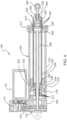
- FIGS. 1 - 4 illustrate multiple views of an assembled blow down actuator assembly 100 in accordance with aspects of the invention.
- the actuator assembly 100 may include a motor 110 operably connected to a drive assembly 200 via a gear train housed in a gear housing 300.
- a mounting device 120 such as a bracket or any other suitable mounting mechanism, may be provided on a surface of the gear housing 300 for mounting the actuator assembly 100 to a stable support structure, such as the body structure of an airplane.
- the drive assembly 200 includes a drive arm assembly 202 for actuation of a controlled member, such as a control surface, door, or a landing gear, for example.
- a distal end of the drive arm assembly 202 may be provided with a connection device 204, such as an eye bolt rod or any other suitable connection device, for connecting the drive arm assembly 202 to the controlled member.
- the actuator assembly may be modular, wherein each of the major components, such as the motor 110 and the drive assembly 200, for example, may be separately and independently attached and/or detached from the gear housing 300 for ease of maintenance and/or replacement.
- a motor mounting plate 112 and/or a drive assembly mounting plate 206 may be provided for mounting the motor 110 and the drive assembly 200 to the gear housing 300 via attachment means, such as bolts or screws.
- FIG. 3 is a side view of the actuator assembly shown in FIGs. 1 and 2 .
- FIG. 4 provides a cross-sectional view of the actuator assembly 100 taken along the cross-sectional plane 4 - 4 of FIG. 3 .
- the motor 110 may have a central drive shaft 114 that is operably connected through gears 116 and 118 to drive a ball screw 208 of the drive assembly 200.
- the drive assembly 200 has a cover tube 210 and end cap 212.
- the end cap 212 has a central orifice 214 through which the drive arm assembly 202 slidably extends.
- a ball nut 216 may be situated on the ball screw 208 such that, during normal operation of the drive assembly 200, rotation of the ball screw 208 forces the ball nut 216 via housed bearings 217 to travel along the raceway defined by the threading on the ball screw 208. The direction of rotation of the ball screw 208 determines whether the drive arm assembly 202 extends or retracts through the central orifice 214.
- a nut adapter 218 may be provided on a distal end of the ball nut 216.
- the nut adapter 218 may be formed with one or more notched seats 220 for seating one or more end portions 222 of one or more release levers 224.
- the release levers 224 may be rotatably mounted on a release cap 226, as described in further detail below.
- the release cap 226 may be fixed to an actuation tube 230, which is the primary longitudinal body component of the piston-like drive arm assembly 202.
- a release tube 234 may be concentrically arranged inside of the actuation tube 230.
- a locking ring 236 is provided that releasably engages the release tube 234 and the actuation tube 230.
- the release tube 234 extends longitudinally within the actuation tube 230 to abut a release piston 238.
- the release piston 238 houses a gas generator 240. As shown in FIG. 4 , a distal end of the actuation tube 230 extends beyond the release tube 234 and the release piston 238 when the release tube 234 and the actuation tube 230 are engaged in a locked position via the locking ring 236.
- a sealing plug 244 may be provided to close the distal end of the actuation tube 230.
- the sealing plug 244 may abut the release piston 238 during normal operation of the drive assembly 200.
- An expansion chamber 250 may be defined between the release piston 238 and the sealing plug 244.
- the release piston 238 and/or the sealing plug 244 may be formed with a recessed area 252 to form the expansion chamber 250.
- the connection device 204 may be mounted, such as by press fit or via a threaded connection, for example, to the sealing plug 244, or may alternatively be integrally formed with the sealing plug 244. Multiple o-rings 254 or other suitable sealing mechanisms may be used to ensure that the expansion chamber 250 is completely sealed.
- the cover tube 210 may be provided with a locking channel 256, or any other suitable detent means, on an interior surface toward the distal end. As will be explained in greater detail below, the locking channel 256 may engage the release levers 224 during emergency operation of the actuator assembly 100.
- FIGs. 5 - 7 illustrate operation of the actuator assembly 100 during a normal mode, in which the motor 110 controls the drive assembly 200 to extend and/or retract the drive arm assembly 202.
- FIGs. 5 and 6 are illustrated with the cover tube 210 and gear housing removed to assist in an understanding of the operation of the internal components.
- FIG. 5 illustrates the actuator assembly 100 with the drive arm assembly 202 in a fully retracted position.
- a signal may be sent to the motor 110 to extend the drive arm assembly 202 to a predetermined position, which may be fully extended and/or any position in between.
- the motor 110 operates through the gear train to turn the ball screw 208, which in turn causes the ball nut 216 to extend along the shaft of the ball screw 208, pushing the drive arm assembly 202 to extend.
- the locking ring 236 is fully engaged with both the actuation tube 230 and the release tube 234.
- the ball nut 216, the nut adapter 218, the actuation tube 230, and the release tube 234 are all engaged to move in unison as one assembly.
- the assembly may thus slide within the cover tube 210 to a desired position. Because the drive arm assembly moves in unison, the end portions 222 of the release levers 224 remain seated in a closed position between the notched seat 220 and the cover tube 210.
- the release levers 224 may be mounted to the release cap 226 by a spring loaded hinge 228 having a spring load forcing the end portions 222 toward the notched seats 220.
- the catch ends 223 of the release levers 224 will not engage the locking channel 256 of the cover tube 210.
- the catch ends 223 of the release levers 224 may only be released to engage the locking channel 256 if the end portions 222 are unseated from the notched seats 220 to permit the spring force of the hinges 228 to rotate the catch ends 223 outward.
- the drive arm assembly 202 may be extended to a fully open position without the actuator assembly 100 being locked by the release levers 224 in the fully open position. The drive arm assembly 202 may thus be retracted from a fully open position as desired.
- FIGS. 7-13 illustrate an emergency mode of operation of the actuator assembly 100, during which aspects of the normal drive assembly are automatically decoupled to permit an emergency extension of the actuation tube 230 into a fully extended, locked position.
- the emergency mode of operation of the actuator assembly 100 could be automatically initiated or, for example, manually initiated by a pilot.
- a signal may be electrically sent to the gas generator 240 to initiate an emergency sequence.
- the emergency mode may be activated by any suitable means, including mechanical actuation methods having an activation switch, such as a piezo switch or a firing pin.
- the ball screw 208 may be hollow to permit a wire to carry the activation signal to the gas generator 240.
- the signal may initiate a process in the gas generator 240 that, for example, similar to conventional airbag devices, mixes sodium azide (NaN 3 ) and potassium nitrate (KNO 3 ) in a reaction that produces a large burst of hot nitrogen gas. The rapid expansion of the nitrogen gas is released into the expansion chamber 250.
- the gas generator 240 may release any combination of chemicals, for example, that are known to rapidly release a supply of pressurized fluid into the expansion chamber 250.
- conventional combustion techniques may be used to generate the necessary rapid pressure increase in the expansion chamber 250 as a result of activation of activation of the emergency backup system.
- the rapid release of pressurized fluid into the expansion chamber 250 simultaneously produces pressure against the release piston 238 and the sealing plug 244.
- the release piston 238 may be formed with a flanged portion 260.
- the flanged portion 260 engages the distal end of the release tube 234 to force the release tube 234 to slide in a direction towards the nut adapter 218 and the locking ring 236.
- a space 235 exists between a proximal end of the release tube and the nut adapter 218. The space 235 allows room for the release tube 234 to release backward during emergency operation.
- the locking ring 236 may be formed with protrusions 237 for engaging slots in the actuation tube 230 and the release tube 234.
- a slot 264 formed in the release tube 234 causes the protrusions 237 of the locking ring 236 to rotate through a slot 266 formed in the actuation tube 230.
- the slot 266 in the actuation tube is formed to permit release of the actuation tube 230 from the locking ring 236 once the locking ring 236 rotates through to the position shown in FIG. 11 .
- a spring 270 may be provided to maintain tension on the release tube 234 to prevent premature actuation due to jarring and/or vibration.
- the release tube 234 is formed to remain engaged with the locking ring 236 throughout the emergency activation procedure. Accordingly, once the actuation tube 230 reaches the position shown in FIG. 11 , as shown in FIG. 12 , the actuation tube 230 is free to extend, sliding past the locked release tube 234 and permitting the expansion chamber 250 to expand under pressure from the gas generator 240. As the actuation tube 230 extends, the release cap 226 mounted thereon also slides away from the ball nut 216 and the nut adapter 218, which remain locked in position by the release tube 234. The end portions 222 of the release levers 224 are thus freed from the notched seats 220 and may rotate inward under spring force from the spring loaded hinges 228.
- the cover tube 210 prevents rotation of the release levers 224 until, as shown in FIG. 13 , the actuation tube 230 is in a fully extended position. At the fully extended position, the catch ends 223 of the release levers 224 are free to rotate into the locking channel 256. The actuation tube 230 may thus be prevented from sliding back into the cover tube 210 and the actuator assembly 100 locked in the fully extended position.
- activation of the emergency procedure may be initiated regardless of the stroke position of the drive arm assembly 202. As such, even if failure occurs during normal operation, midway through a procedure such as the lowering of landing gear, emergency activation of the blow down actuator assembly 100 automatically decouples those aspects of the actuator assembly 100 associated with the normal drive mode and permits full extension of the actuation tube 230 into a locked position via those aspects of the actuator assembly 100 associated with the integrated emergency backup system.
- a pressure relief valve may be provided to relieve excess pressure from the expansion chamber 250, particularly in the event the emergency mode is activated when the normal drive system has the drive arm assembly 202 in a nearly extended position. In that case, the expansion chamber 250 will not need to expand nearly as much as during the situation when the drive arm assembly 202 is in a substantially retracted position.
- the integrated emergency back-up actuation system described herein may be applied to non-linear actuator drive assemblies, for example, a rotary actuator.
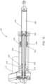
- FIGS. 14 and 15 illustrate an assembled blow down actuator assembly 1100 in accordance with yet other aspects of the invention
- the actuator assembly 1100 may include an electric motor 1110 operably connected to a drive assembly 1200 via a gear train housed in a gear housing 1300.
- a mounting device 1120 such as a bracket or any other suitable mounting mechanism, may be provided on a surface of the gear housing 1300 for mounting the actuator assembly 1100 to a stable support structure, such as the body structure of an airplane.
- the drive assembly 1200 includes a drive arm assembly 1202 for actuation of a controlled member, such as a control surface, door, or a landing gear, for example.
- a distal end of the drive arm assembly 1202 may be provided with a connection device 1204, such as an eye bolt rod or any other suitable connection device, for connecting the drive arm assembly 1202 to the controlled member.
- the actuator assembly may be modular, wherein each of the major components, such as the motor 1110 and the drive assembly 1200, for example, may be separately and independently attached and/or detached from the gear housing 1300 for ease of maintenance and/or replacement.
- a motor mounting plate 1112 and/or a drive assembly mounting plate 1206 may be provided for mounting the motor 1110 and the drive assembly 1200 to the gear housing 1300 via attachment means, such as bolts or screws.
- FIG. 15 provides a cross-sectional view of the actuator assembly 1100.
- the motor 1110 may have a central drive shaft 1114 that is operably connected through gears 1116 and 1118 to drive a ball screw 1208 of the drive assembly 1200.
- the drive assembly 1200 has a cover tube 1210 and end cap 1212.
- the end cap 1212 has a central orifice 1214 through which the drive arm assembly 1202 slidably extends.
- a housing 1211 for an expandable retaining ring assembly 1213 may be configured toward the distal end of the cover tube 1210.
- a ball nut 1216 may be situated on the ball screw 1208 such that, during normal operation of the drive assembly 1200, rotation of the ball screw 1208 forces the ball nut 1216 via housed bearings 1217 to travel along the raceway defined by the threading on the ball screw 1208. The direction of rotation of the ball screw 1208 determines whether the drive arm assembly 1202 extends or retracts through the orifice 1214.
- a nut adapter 1218 may be provided on a distal end of the ball nut 1216.
- An actuation tube 1230 which is the primary longitudinal body component of the piston-like drive arm assembly 1202 may be concentrically arranged around a release tube 1234.
- the release tube 1234 extends longitudinally within the actuation tube 1230 to abut a release piston 1238.
- a distal end of the actuation tube 1230 extends beyond the release tube 1234 and the release piston 1238 when the release tube 1234 and the actuation tube 1230 are engaged in a locked position via a securing mechanism, and a proximal end of the actuation tube 1230 may be configured with a retention groove 1231.
- a sealing plug 1244 is provided to close the distal end of the actuation tube 1230.
- the sealing plug 1244 may abut the release piston 1238 during normal operation of the drive assembly 1200.
- An expansion chamber 1250 may be defined between the release piston 1238 and the sealing plug 1244.
- the release piston 1238 and/or the sealing plug 1244 may be formed with a recessed area 1252 to form the expansion chamber 1250.
- the connection device 1204 may be mounted, such as by press fit or via a threaded connection, for example, to the sealing plug 1244, or may alternatively be integrally formed with the sealing plug 1244. Multiple o-rings or other suitable sealing mechanisms may be used to ensure that the expansion chamber 1250 is completely sealed.
- FIGS. 16 and 17 illustrate operation of the actuator assembly 1100 during a normal mode, in which the motor 1110 controls the drive assembly 1200 to extend and/or retract the drive arm assembly 1202.
- FIGs. 16 and 17 are illustrated with the cover tube 1210 and gear housing removed to assist in an understanding of the operation of the internal components.
- FIG. 16 illustrates the assembly 1100 with the drive arm assembly 1202 in a fully retracted position.
- a signal may be sent to the motor 1110 to extend the drive arm assembly 1202 to a predetermined position, which may be fully extended and/or any position in between.
- the motor 1110 operates through the gear train to turn the ball screw 1208, which in turn causes the ball nut 1216 to extend along the shaft of the ball screw 1208, pushing the drive arm assembly 1202 to extend.
- the actuation tube 1230 and the release tube 1234 may be engaged by a retaining pin 1215 that slides in a slot 1219 provided in the nut adapter 1218.
- the retaining pin 1215 ensures that both the actuation tube 1230 and the release tube 1234 are fully engaged such that the ball nut 1216, the nut adapter 1218, the actuation tube 1230, and the release tube 1234 are all secured to move in unison as one assembly.
- the assembly may thus slide within the cover tube 1210 (not shown in FIGS. 18 and 18 ) to a desired position.
- the nut adapter 1218 may be formed with ramped extensions 1221.
- the function of the ramped extensions 1221 is explained in further detail below. However, during normal operations, the ramped extensions 1221 prevent the expandable retaining ring assembly 1213 from engaging the retention groove 1231 on the actuation tube 1230.
- FIGS. 20-22 illustrate an emergency mode of operation of the actuator assembly 1100, during which aspects of the normal drive assembly may be automatically decoupled to permit an emergency extension of the actuation tube 1230 into a fully extended, locked position.
- the emergency mode of operation of the actuator assembly 1100 could be automatically initiated or, for example, manually initiated by a pilot.
- a signal may be electrically sent to actuate a source of pressurized gas into the hollow tube portion of the ball screw 1208.
- the emergency mode may be activated by any suitable means, including mechanical actuation methods having an activation switch, such as a piezo switch or a firing pin.
- Any suitable pressurized gas such as nitrogen, may be provided from a pressurized gas source, such as a gas generator (not shown), attached to or situated near the assembly 1100 or connected by a conduit for delivery from any external location.
- a pressurized gas source such as a gas generator (not shown)
- Various types of pressure connection fittings for attachment of a pressure conduit may be configured into the assembly to allow for quick attachment or detachment to the source of pressurized gas.
- the pressurized gas may be delivered into the proximal end of the hollow tube portion of the ball screw 1208, and forced into the expansion chamber 1250.
- the release piston 1238 may be formed with a flanged portion 1260.
- the flanged portion 2160 engages the distal end of the release tube 1234 to force the release tube 1234 to slide in a direction towards the nut adapter 1218 and the retaining pin 1215.
- the retaining pin 1215 slides in the slot on the nut adapter 1218 and forces the release tube 1234 to rotate into a position in which the actuation tube 1230 is free to disengage from the release tube 1234 and the nut adapter 1218.
- Detents, grooves, a spring pin, and/or any suitable means for permitting disengagement of the actuation tube 1230 from the release tube 1234 may be used. Accordingly, as shown in FIG. 22 , with the actuation tube 1230 disengaged from the release tube 1234 and the nut adapter 1218, the actuation tube 1230 is free to extend due to the pressure increasing the expansion of the expansion chamber 1250.
- a spring 1270 (see FIGS. 20 and 21 ) may be provided to maintain tension on the release tube 1234 to prevent premature actuation due to jarring and/or vibration.
- the release tube 1234 is formed to remain engaged with the nut adapter 1218 and the ball nut 1216 via the retaining pin 1215 throughout the emergency activation procedure.
- the actuation tube 1230 extends until, as shown in FIG. 23 , the retention groove 1231 on the actuation tube 1230 enters the housing 1211 wherein the expandable retaining ring assembly 1213 is forced by biasing means to compress into the retention groove 1231 for locking the actuation tube 1230 into an fully extended position.
- the expandable retaining ring assembly 1213 may be configured to be four quarter circle ring pieces for example, which are spring actuated into a biasing position toward the actuation tube 1230.
- the expandable retaining ring assembly 1213 is prevented from compression by the exterior wall of the actuation tube 1230.
- the ramped extensions 1221 on the nut adapter 1218 are formed to align with grooves 1229 configured at predetermined locations on the free end periphery of the actuation tube 1230.
- the ramped extensions 1221 are seated in the grooves 1229 and extend across the retention groove 1231.
- the ramped extensions 1221 prevent the retaining ring assembly 1213 from compressing into the retention groove 1231.
- the ramped extensions 1221 permit proper retraction of the actuation tube 1230.
- the ramped extensions 1221 on the nut adapter 1218 are also configured to disengage an engaged retention ring 1213 to permit a reset of the actuator assembly 1100 once the emergency situation is resolved.
- the blow down actuator assembly 1100 does not thus require complete disassembly and reassembly to reset for the next emergency operation.
- the ball screw 1208 may be actuated to move the ball nut 1216, nut adapter 1218, and release tube 1234 as a unit toward the actuation tube 1230 that is locked in the extended position by the retention ring 1213 being biased into the retention groove 1231.
- the ramped extensions 1221 slide toward the housing 1211 and into the grooves 1229 (see FIG. 25 ). Continued turning of the ball screw 1208 forces the ramped extensions 1221 to push under and expand the expanding ring assembly 1213 to disengage the ring assembly 1213 from the retention groove 1231.
- the release tube 1234 may thus reengage the actuation tube 1230 such that the entire arm assembly, now assembly, is reset and may be retracted into housing 1211 to operate under normal conditions. The procedure may be repeated as necessary as long as a pressure source is replaced or configured to supply pressurized gas to the assembly 1100 during a subsequent emergency situation.
- activation of the emergency procedure may be initiated regardless of the stroke position of the drive arm assembly 1202. As such, even if failure occurs during normal operation, midway through a procedure such as the lowering of landing gear, emergency activation of the blow down actuator assembly 1100 automatically decouples those aspects of the assembly 1100 associated with the normal drive mode and permits full extension of the actuation tube 1230 into a locked position via those aspects of the assembly 1100 associated with the integrated emergency backup system.
- a pressure relief valve may be provided to relieve excess pressure from the expansion chamber 1250, particularly in the event the emergency mode is activated when the normal drive system has the drive arm assembly 1202 in a nearly extended position. In that case, the expansion chamber 1250 will not need to expand nearly as much as during the situation when the drive arm assembly 1202 is in a substantially retracted position.
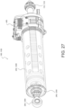
- FIG. 27 is a perspective front view of a blow down actuator assembly in accordance with further aspects of the disclosure.
- FIG. 27 illustrates a further aspect of the blow down actuator assembly 100 illustrated in FIGs. 1 - 13 ; and FIG. 27 likewise illustrates a further aspect of the blow down actuator assembly 1100 illustrated in FIGs. 14 - 26 .
- the actuation assembly of FIG. 27 includes the addition of a drag brake assembly 400 to the blow down actuator assembly 100, 1100.
- the drag brake assembly 400 may be configured to control the rate of extension or movement of the actuation tube 230, 1230.
- the actuation tube 230, 1230 may be subjected to a substantial amount of gas pressure within the expansion chamber 250, 1250.
- the gas pressure within the expansion chamber 250, 1250 may cause the actuation tube 230, 1230 to move to the extended position, in some scenarios, more rapidly than desired.
- a drag brake assembly 400 may be implemented in the blow down actuator assembly 100, 1100.
- the drag brake assembly 400 may be configured to slow, damp, or otherwise control movement of the actuation tube 230, 1230 during the emergency mode of operation.
- the drag brake assembly 400 may utilize any type of braking technology, such as, frictional type braking technology. Of course, other types of braking technology or damping technology are contemplated as well.
- the drag brake assembly 400 may be arranged on the blow down actuator assembly 100, 1100 such that it may be configured to slow, damp, or otherwise control movement of the actuation tube 230, 1230 during the emergency mode of operation.
- FIG. 28 is a perspective front view of the blow down actuator assembly of FIG. 27 in an emergency mode of operation.
- the drag brake assembly 400 is partially arranged on the actuation tube 230, 1230 and partially on the release tube 234, 1234.
- the release tube 234, 1234 may include a drag brake rack 404.
- the drag brake rack 404 may include a plurality of teeth arranged in a linear configuration along a longitudinal length of the release tube 234, 1234.
- the drag brake rack 404 may be arranged along a side surface of the release tube 234, 1234.
- the drag brake assembly 400 may further include a drag brake pinion 402 that has a generally cylindrical construction with teeth arranged circumferentially about the drag brake pinion 402.
- the teeth of the drag brake pinion 402 may be configured to engage the plurality of teeth of the drag brake rack 404.
- the drag brake pinion 402 rotates in response to movement along the drag brake rack 404 to slow, damp, or otherwise control movement of the actuation tube 230, 1230.
- the drag brake pinion 402 may include one or more braking components to slow, damp, or otherwise control rotational movement thereof.
- the braking components may include one or more brake shoes and one or more brake disks as discussed in greater detail below. However, other types of braking components are contemplated as well.
- FIG. 29 is a partial exploded perspective front view of the blow down actuator assembly FIG. 27 ; and FIG. 30 is another partial exploded perspective front view of the blow down actuator assembly FIG. 27 .
- FIGs. 29 - 30 show further details of the drag brake assembly 400.
- the drag brake assembly 400 may include an upper bracket 420 and a lower bracket 418 configured to be attached to one end of the actuation tube 230, 1230.
- the upper bracket 420 and the lower bracket 418 may be further configured to hold the drag brake pinion 402 in a position to engage the drag brake rack 404.
- the upper bracket 420 and the lower bracket 418 may be further configured to hold the brake shoes 424 and the brake disks 422.
- the upper bracket 420 and the lower bracket 418 may be further configured to hold brake shoe guide rods 416.
- the brake shoe guide rods 416 may be configured to be inserted into corresponding apertures 436 in each of the brake shoes 424 shown in FIG. 32 .
- the brake shoe guide rods 416 may be configured to prevent rotation of the brake shoes 424.
- the brake shoe guide rods 416 may be configured to allow movement of the brake shoes 424 along the brake shoe guide rods 416.
- the drag brake assembly 400 may further include a brake spring arm 408 configured to hold a spring cap 412, a Belleville disk spring 414, and a torque adjustment screw 410 in a configuration arranged above the brake shoes 424 and brake disks 422. This construction applies a downward force on the brake shoes 424 and brake disks 422 to create friction that slows movement of the drag brake pinion 402.
- the torque adjustment screw 410 may be configured to adjust a force on the brake shoes 424 and brake disks 422 to adjust the friction and thus adjust the rotational movement of the drag brake pinion 402.
- the drag brake assembly 400 may further include a bushing cap 434.
- the bushing cap 434 may hold the drag brake pinion 402 to the lower bracket 418 with fasteners 406 and hold the drag brake pinion 402 to the upper bracket 420 with fasteners 456.
- FIG. 31 is a partial exploded perspective view of brake components of the blow down actuator assembly of FIG. 27 ;
- FIG. 32 is another partial exploded perspective view of brake components of the blow down actuator assembly of FIG. 27 ;
- FIG. 33 is another partial exploded perspective view of brake components of the blow down actuator assembly of FIG. 27 .
- FIG. 30 shows a plurality of brake shoes 424. In one aspect, there are four brake shoes 424. However, any number of brake shoes 424 are contemplated.
- FIG. 30 further shows a plurality of brake disks 422. In one aspect, there are three brake disks 422. However, any number of brake disks 422 are contemplated.
- the brake shoes 424 may have a single large aperture 442 configured to receive a brake shaft 426 and are configured to slide vertically up and down the brake shaft 426. Moreover, the brake shoes 424 may include one or more additional smaller apertures 436 configured to receive the brake shoe guide rods 416. As previously noted, the brake shoe guide rods 416 may be configured to prevent rotational movement of the brake shoes 424 and may be configured to allow movement of the brake shoes 424 along the brake shoe guide rods 416.
- the brake disks 422 may also include a single aperture 440 configured to receive the brake shaft 426. Moreover, the brake disks 422 may further include key extensions 442 within the single aperture 440 of the brake disks 422. The key extensions 442 may be configured to be received in a key slot 444 of the brake shaft 426. The combination of the key extensions 442 and the key slot 444 are configured to rotate the brake disks 422 consistent with the rotational movement of the brake shaft 426. Accordingly, the brake shoes 424 do not rotate with respect to the brake shaft 426 and the brake disks 422 do rotate with rotational movement of the brake shaft 426. Thus, the brake shoes 424 generate friction with respect to the brake disks 422 during rotational movement of the brake shaft 426.
- the brake shaft 426 may include a plurality of apertures 446 along a lower end thereof.
- the plurality of apertures 446 may each be configured to receive a ball spring 430.
- the ball spring 430 may be formed of a polymer material.
- the apertures 446 may also receive a ratchet ball 428.
- the configuration of the ball springs 430 and the ratchet balls 428 may be such that the ball springs 430 provide a spring force to extend the ratchet balls 428 circumferentially outward from the brake shaft 426.
- the ratchet balls 428 may contact the drag brake pinion 402 and engage therewith.
- the drag brake pinion 402 may include an internal geometry 450 in an internal diameter thereof to engage the ratchet balls 428 as shown in FIG. 33 .
- the internal geometry 450 may be configured to engage the ratchet balls 428 when the drag brake pinion 402 rotates in a first direction while providing a braking force during their emergency mode; and the internal geometry 450 may be configured to disengage the ratchet balls 428 when the drag brake pinion 402 rotates in a second direction, opposite to the first direction, while the blow down actuator assembly 100, 1100 is being reset as described in greater detail below.
- the internal geometry 450 may be ramped along one surface 452 such that it forces the ratchet balls 428 back into the apertures of the brake shaft 426; and the geometry may include an engagement surface 454 along a second surface such that engages the ratchet balls 428 and limits their movement into the apertures of the brake shaft 426.
- the brake shaft 426 may include a bushing 432 and a bushing 438 to support the drag brake pinion 402.
- the drag brake assembly 400 During normal operation (Primary mode) the drag brake assembly 400 is not used.
- the purpose of the drag brake assembly 400 is to control the rate of extension and any adding loads on the actuation tube 230, 1230 during a secondary (emergency mode) extension.
- the drag brake assembly 400 operation is utilized during secondary operation or emergency mode extension.
- gas enters the expansion chamber 250, 1250 and forces the release tube 234, 1234 in a rearward direction.
- the de-coupler mechanism e.g., the locking ring 236, the slot 266, the retaining pin 1215, the slot 1219, and/or the like
- the de-coupler mechanism is activated and releases the actuation tube 230, 1230 (see for example FIG. 28 ).
- the drag brake pinion 402 may always be engaged to the drag brake rack 404 as shown in FIGs. 27 and 28 .
- the drag brake rack 404 may be fastened to a roller nut assembly (ball nut 216, the nut adapter 218, and/or the like) and may be stationary with respect to the actuation tube 230, 1230. As the gas expands, the actuation tube 230, 1230 slides down the release tube 234, 1234 causing the drag brake rack 404 to rotate the drag brake pinion 402.
- the drag brake pinion 402 may be attached to the brake shaft 426 by the ratchet balls 428 as shown in FIGs. 30 - 32 .
- the brake shaft 426 may be connected to the brake disk 422 by the keyed slot 444 in the brake shaft 426.
- the brake shoes 424 may be positioned on either side of the brake disks 422 and form a stack.
- the brake shoes 424 also slide over the brake shoe guide rods 416 and shown in FIG. 30 . This may prevent the brake shoes 424 from rotating.
- the brake spring arm 408, the spring cap 412, and the Belleville disk springs 414 may be assembled in a way that they apply a force on the stack of brake shoes 424 and the brake disks 422. The application of force is controlled by the torque adjustment screw 410.
- the force applied to the brake stack may cause friction between the rotating brake disks 422 and stationary brake shoes 424. This friction generates a torque when the brake shaft 426 is rotated. This action slows the extension of the actuation tube 230, 1230 to a desired level.
- the blow down actuator assembly 100, 1100 may be reset.
- the sequence of events to reset the blow down actuator assembly 100, 1100 from the secondary mode (emergency mode) to primary mode may include allowing gas to be vented out of the blow down actuator assembly 100, 1100.
- the motor 110, 1110 used for the primary mode may be commanded to the extended position.
- the roller nut assembly (ball nut 216, the nut adapter 218, and/or the like) may move forward toward the extended position, for re-coupling, the drag brake rack 404 rotates the drag brake pinion 402.
- the drag brake pinion 402 may now be rotating in the opposite direction from when it was deployed.
- the ratchet balls 428 are held against the inside diameter of the drag brake pinion 402 by the pressure of the polymer springs 430.
- the drag brake pinion 402 may have an internal geometry 450 cut into the inside diameter (for example, ramped on one side 452 and curved on the other side 454) that allows the ratchet balls 428 to grip the inside diameter of a hub of the drag brake pinion 402 when the blow down actuator assembly 100, 1100 is extending by secondary means, and may be configured to free wheel during the reset operation. This allows the drag brake assembly 400 to brake the loads during an extend procedure (emergency mode extension) and free wheel during a reset procedure. In other words, the drag brake pinion 402 forms a ratchet hub.
Description
- This application is a continuation in part of Application No.
15/785,962 filed October 17, 2017 14/591,602, filed January 7, 2015 United States Patent Number: 9,790,969 PCT/US2013/044068, filed June 4, 2013 designating the U.S., which claims priority to provisional Patent Application No.61/655,331, filed June 4, 2012 - The invention relates to actuator mechanisms, more particularly to an actuator assembly having an integrated emergency backup system. The invention further relates to actuator mechanisms having an integrated emergency backup system having a drag brake.
- Mechanical linear actuators are used for translating rotational motion to linear motion. For example, ball screws are linear actuators that rely on a threaded shaft and a nut housing. The nut housing typically contains ball bearings that engage a helical raceway defined by the threaded shaft. Thus, rotational movement of the shaft translates into linear movement of the nut housing along the shaft. These types of linear actuators are often used in aeronautical applications, for example, to control movement of control surfaces, open and close windows, doors, and/or access panels, and control the extension of landing gear. Linear actuators are also often used to convert rotary motion from an electric motor to axial movement of a steering rack in vehicular power steering systems and for precision control in robotic manufacturing.
- Particularly in aeronautical applications, the failure of a mechanical linear drive system can have catastrophic consequences. The failure of one or more aspects of the drive system, such as the motor, the gear train, or the ball screw drive, may result, for example, in the landing gear of an airplane failing to extend or to extend into a fully locked open position. Accordingly, emergency systems are often provided that override and/or bypass the mechanical linear drive system to address such failures. However, these systems are often separate assemblies from the drive assembly, requiring additional space and hardware to accommodate the assembly.
-
US2015/291278 provides apparatuses configured to deploy a landing gear of an aircraft, comprising: a landing gear coupler configured to couple with the landing gear; a release link configured to cooperate the landing gear coupler with a drive shaft that is configured to drive the landing gear between a stowed position and a deployed position; an override driver cooperated with the landing gear coupler; wherein the release link is configured to releasably maintain a relative position of landing gear coupler relative to the drive shaft, and the release link is configured to disengage a coupling between the drive shaft and the landing gear coupler such that the landing gear coupler is configured to move independent of the drive shaft; and wherein the override driver is configured to drive the landing gear coupler to the deployed position. - There is a need and desire for an actuator assembly that has an integrated emergency system, a system that automatically decouples aspects of the system from the normal drive configuration during an emergency.
- The invention concerns an actuation assembly according to
claim 1. An aspect of the actuator assembly according to the invention includes an actuation member, a release member, and a source of pressurized gas, wherein during a normal mode of operation, the actuation member and the release member are engaged to move in unison, and wherein during an emergency mode of operation, pressurized gas automatically decouples the actuation member from the release member to move separately. - In accordance with a preferred embodiment, the actuation assembly includes an electro-mechanical drive system consisting of a ball screw and nut and an integrated backup system operated by a gas generator, wherein when the backup system is activated, the electro-mechanical drive system is decoupled and the actuator moves to a predetermined position and mechanically locks in place.
- There has thus been outlined, rather broadly, certain aspects of the invention in order that the detailed description thereof may be better understood, and in order that the present contribution to the art may be better appreciated. There are, of course, additional aspects of the disclosure that will be described below and which will form the subject matter of the claims appended hereto.
- The accompanying drawings, which are incorporated in and constitute a part of this specification, illustrate various aspects consistent with the invention, and, together with the description, serve to explain the principles of the invention.
-
FIG. 1 is a front perspective view of a blow down actuator assembly, in accordance with certain aspects of the invention. -
FIG. 2 is another perspective view of a blow down actuator assembly, in accordance with certain aspects of the invention. -
FIG. 3 is a side view of a blow down actuator assembly, in accordance with certain aspects of the invention. -
FIG. 4 is a cross-sectional view of the blow down actuator assembly as seen along line 4 - 4 inFIG. 3 , in accordance with certain aspects of the invention. -
FIG. 5 is a front perspective view of a blow down actuator assembly with a cover tube and gear housing removed to illustrate internal components of the assembly, in accordance with certain aspects of the invention. -
FIG. 6 is a front perspective view of a blow down actuator assembly with a cover tube and gear housing removed and with the drive arm assembly in an extended position of use, in accordance with certain aspects of the invention. -
FIG. 7 is a cutaway front view of a blow down actuator assembly, in accordance with certain aspects of the invention. -
FIG. 8 is a close-up cutaway view of aspects of a blow down actuator assembly, in accordance with certain aspects of the invention. -
FIGS. 9-11 illustrate in series a locking ring mechanism for use on a blow down actuator assembly, in accordance with certain aspects of the invention. -
FIG. 12 is a cutaway front view of a blow down actuator assembly in an emergency mode of operation, in accordance with certain aspects of the invention. -
FIG. 13 is a cutaway front view of a blow down actuator assembly in an emergency mode of operation fully extended and mechanically locked, in accordance with certain aspects of the invention. -
FIG. 14 is a perspective view of a blow down actuator assembly, in accordance with certain aspects of the invention. -
FIG. 15 is a cutaway front view of the blow down actuator assembly shown inFIG. 14 , in accordance with certain aspects of the invention. -
FIG. 16 is a front perspective view of the blow down actuator assembly shown inFIG. 14 with a cover tube and gear housing removed to illustrate internal components of the assembly, in accordance with certain aspects of the invention. -
FIG. 17 is a front perspective view of the blow down actuator assembly shown inFIG. 14 with a cover tube and gear housing removed and with the drive arm assembly in an extended position of use, in accordance with certain aspects of the invention. -
FIG. 18 is a close-up cutaway view of aspects of the blow down actuator assembly shown inFIG. 14 , in accordance with certain aspects of the invention. -
FIG. 19 is a front cutaway view of aspects of the blow down actuator assembly shown inFIG. 14 , in accordance with certain aspects of the invention. -
FIGS. 20 and 21 illustrate in series a securing mechanism for use on a blow down actuator assembly, in accordance with certain aspects of the invention. -
FIG. 22 is a cutaway front view of the blow down actuator assembly shown inFIG. 14 with a cover tube removed to illustrate internal components in an emergency mode of operation, in accordance with certain aspects of the invention. -
FIG. 23 is a close-up cutaway perspective view with a cover tube removed to illustrate internal components of the blow down actuator assembly shown inFIG. 14 in an emergency mode of operation, in accordance with certain aspects of the invention. -
FIGS. 24 to 26 illustrate in series the blow down actuator assembly shown inFIG. 14 with a cover tube removed to illustrate a reengagement procedure following an emergency procedure, in accordance with certain aspects of the invention. -
FIG. 27 is a perspective front view of a blow down actuator assembly in accordance with further aspects of the invention. -
FIG. 28 is a perspective front view of the blow down actuator assembly ofFIG. 27 in an emergency mode of operation. -
FIG. 29 is a partial exploded perspective front view of the blow down actuator assembly ofFIG. 27 . -
FIG. 30 is another partial exploded perspective front view of the blow down actuator assembly ofFIG. 27 . -
FIG. 31 is a partial exploded perspective view of brake components of the blow down actuator assembly ofFIG. 27 . -
FIG. 32 is another partial exploded perspective view of brake components of the blow down actuator assembly ofFIG. 27 . -
FIG. 33 is another partial exploded perspective view of brake components of the blow down actuator assembly ofFIG. 27 . - The invention will now be described with reference to the drawing figures, in which like reference numerals refer to like parts throughout.
- Various aspects of an actuator assembly may be illustrated by describing components that are coupled, attached, and/or joined together. As used herein, the terms "coupled", "attached", and/or "joined" are used to indicate either a direct connection between two components or, where appropriate, an indirect connection to one another through intervening or intermediate components. In contrast, when a component is referred to as being "directly coupled," "directly attached," and/or "directly joined" to another component, there are no intervening elements present.
- Relative terms such as "lower" or "bottom" and "upper" or "top" may be used herein to describe one element's relationship to another element illustrated in the drawings. It will be understood that relative terms are intended to encompass different orientations of an electric strike assembly in addition to the orientation depicted in the drawings. By way of example, if aspects of an actuator assembly shown in the drawings are turned over, elements described as being on the "bottom" side of the other elements would then be oriented on the "top" side of the other elements. The term "bottom" can therefore encompass both an orientation of "bottom" and "top" depending on the particular orientation of the apparatus.
-
FIGS. 1 - 4 illustrate multiple views of an assembled blow downactuator assembly 100 in accordance with aspects of the invention. Theactuator assembly 100 may include amotor 110 operably connected to adrive assembly 200 via a gear train housed in agear housing 300. A mountingdevice 120, such as a bracket or any other suitable mounting mechanism, may be provided on a surface of thegear housing 300 for mounting theactuator assembly 100 to a stable support structure, such as the body structure of an airplane. Thedrive assembly 200 includes adrive arm assembly 202 for actuation of a controlled member, such as a control surface, door, or a landing gear, for example. A distal end of thedrive arm assembly 202 may be provided with aconnection device 204, such as an eye bolt rod or any other suitable connection device, for connecting thedrive arm assembly 202 to the controlled member. - As shown in
FIG. 2 , the actuator assembly may be modular, wherein each of the major components, such as themotor 110 and thedrive assembly 200, for example, may be separately and independently attached and/or detached from thegear housing 300 for ease of maintenance and/or replacement. Amotor mounting plate 112 and/or a driveassembly mounting plate 206 may be provided for mounting themotor 110 and thedrive assembly 200 to thegear housing 300 via attachment means, such as bolts or screws. -
FIG. 3 is a side view of the actuator assembly shown inFIGs. 1 and2 .FIG. 4 provides a cross-sectional view of theactuator assembly 100 taken along the cross-sectional plane 4 - 4 ofFIG. 3 . Themotor 110 may have acentral drive shaft 114 that is operably connected throughgears ball screw 208 of thedrive assembly 200. Thedrive assembly 200 has acover tube 210 andend cap 212. Theend cap 212 has acentral orifice 214 through which thedrive arm assembly 202 slidably extends. Aball nut 216 may be situated on theball screw 208 such that, during normal operation of thedrive assembly 200, rotation of theball screw 208 forces theball nut 216 via housedbearings 217 to travel along the raceway defined by the threading on theball screw 208. The direction of rotation of theball screw 208 determines whether thedrive arm assembly 202 extends or retracts through thecentral orifice 214. - A
nut adapter 218 may be provided on a distal end of theball nut 216. Thenut adapter 218 may be formed with one or more notchedseats 220 for seating one ormore end portions 222 of one or more release levers 224. The release levers 224 may be rotatably mounted on arelease cap 226, as described in further detail below. - The
release cap 226 may be fixed to anactuation tube 230, which is the primary longitudinal body component of the piston-likedrive arm assembly 202. Arelease tube 234 may be concentrically arranged inside of theactuation tube 230. A lockingring 236 is provided that releasably engages therelease tube 234 and theactuation tube 230. Therelease tube 234 extends longitudinally within theactuation tube 230 to abut arelease piston 238. Therelease piston 238 houses agas generator 240. As shown inFIG. 4 , a distal end of theactuation tube 230 extends beyond therelease tube 234 and therelease piston 238 when therelease tube 234 and theactuation tube 230 are engaged in a locked position via thelocking ring 236. - A sealing
plug 244 may be provided to close the distal end of theactuation tube 230. The sealingplug 244 may abut therelease piston 238 during normal operation of thedrive assembly 200. Anexpansion chamber 250 may be defined between therelease piston 238 and the sealingplug 244. For example, therelease piston 238 and/or the sealingplug 244 may be formed with a recessedarea 252 to form theexpansion chamber 250. Theconnection device 204 may be mounted, such as by press fit or via a threaded connection, for example, to the sealingplug 244, or may alternatively be integrally formed with the sealingplug 244. Multiple o-rings 254 or other suitable sealing mechanisms may be used to ensure that theexpansion chamber 250 is completely sealed. - In accordance with other aspects of the invention, the
cover tube 210 may be provided with a lockingchannel 256, or any other suitable detent means, on an interior surface toward the distal end. As will be explained in greater detail below, the lockingchannel 256 may engage the release levers 224 during emergency operation of theactuator assembly 100. -
FIGs. 5 - 7 illustrate operation of theactuator assembly 100 during a normal mode, in which themotor 110 controls thedrive assembly 200 to extend and/or retract thedrive arm assembly 202.FIGs. 5 and6 are illustrated with thecover tube 210 and gear housing removed to assist in an understanding of the operation of the internal components. - In particular,
FIG. 5 illustrates theactuator assembly 100 with thedrive arm assembly 202 in a fully retracted position. To control movement of a controlled device, e.g., a landing gear, a signal may be sent to themotor 110 to extend thedrive arm assembly 202 to a predetermined position, which may be fully extended and/or any position in between. As shown inFIG. 6 , themotor 110 operates through the gear train to turn theball screw 208, which in turn causes theball nut 216 to extend along the shaft of theball screw 208, pushing thedrive arm assembly 202 to extend. - As shown in
FIG. 7 , in a normal mode of operation, thelocking ring 236 is fully engaged with both theactuation tube 230 and therelease tube 234. As such, theball nut 216, thenut adapter 218, theactuation tube 230, and therelease tube 234 are all engaged to move in unison as one assembly. The assembly may thus slide within thecover tube 210 to a desired position. Because the drive arm assembly moves in unison, theend portions 222 of the release levers 224 remain seated in a closed position between the notchedseat 220 and thecover tube 210. - The release levers 224 may be mounted to the
release cap 226 by a spring loadedhinge 228 having a spring load forcing theend portions 222 toward the notched seats 220. Thus, during normal operation, the catch ends 223 of the release levers 224 will not engage the lockingchannel 256 of thecover tube 210. The catch ends 223 of the release levers 224 may only be released to engage the lockingchannel 256 if theend portions 222 are unseated from the notchedseats 220 to permit the spring force of thehinges 228 to rotate the catch ends 223 outward. In this manner, during normal mode operation, thedrive arm assembly 202 may be extended to a fully open position without theactuator assembly 100 being locked by the release levers 224 in the fully open position. Thedrive arm assembly 202 may thus be retracted from a fully open position as desired. -
FIGS. 7-13 illustrate an emergency mode of operation of theactuator assembly 100, during which aspects of the normal drive assembly are automatically decoupled to permit an emergency extension of theactuation tube 230 into a fully extended, locked position. For example, if during flight there is a malfunction of a component of theactuator assembly 100, such as the motor, the gear train, and/or the ball screw/ball nut, the landing gear may be prevented from achieving full extension. Accordingly, in this situation, the emergency mode of operation of theactuator assembly 100 could be automatically initiated or, for example, manually initiated by a pilot. As shown inFIG. 7 , if the emergency mode is initiated, a signal may be electrically sent to thegas generator 240 to initiate an emergency sequence. In accordance with other aspects of the invention, the emergency mode may be activated by any suitable means, including mechanical actuation methods having an activation switch, such as a piezo switch or a firing pin. In accordance with yet other aspects of the invention, theball screw 208 may be hollow to permit a wire to carry the activation signal to thegas generator 240. The signal may initiate a process in thegas generator 240 that, for example, similar to conventional airbag devices, mixes sodium azide (NaN3) and potassium nitrate (KNO3) in a reaction that produces a large burst of hot nitrogen gas. The rapid expansion of the nitrogen gas is released into theexpansion chamber 250. In yet other aspects of the disclosure, thegas generator 240 may release any combination of chemicals, for example, that are known to rapidly release a supply of pressurized fluid into theexpansion chamber 250. In accordance with yet other aspects of the disclosure, conventional combustion techniques may be used to generate the necessary rapid pressure increase in theexpansion chamber 250 as a result of activation of activation of the emergency backup system. - The rapid release of pressurized fluid into the
expansion chamber 250 simultaneously produces pressure against therelease piston 238 and the sealingplug 244. Therelease piston 238 may be formed with aflanged portion 260. When pressure is applied against therelease piston 238, theflanged portion 260 engages the distal end of therelease tube 234 to force therelease tube 234 to slide in a direction towards thenut adapter 218 and thelocking ring 236. As shown inFIG. 7 , during normal operation, aspace 235 exists between a proximal end of the release tube and thenut adapter 218. Thespace 235 allows room for therelease tube 234 to release backward during emergency operation. - As shown in the cutaway view of
FIG. 8 , thelocking ring 236 may be formed withprotrusions 237 for engaging slots in theactuation tube 230 and therelease tube 234. As shown in close-up series inFIGs. 9 - 11 , as therelease tube 234 is forced back by the increasing pressure in theexpansion chamber 250, aslot 264 formed in therelease tube 234 causes theprotrusions 237 of thelocking ring 236 to rotate through aslot 266 formed in theactuation tube 230. Theslot 266 in the actuation tube is formed to permit release of theactuation tube 230 from thelocking ring 236 once the lockingring 236 rotates through to the position shown inFIG. 11 . Aspring 270 may be provided to maintain tension on therelease tube 234 to prevent premature actuation due to jarring and/or vibration. - The
release tube 234 is formed to remain engaged with thelocking ring 236 throughout the emergency activation procedure. Accordingly, once theactuation tube 230 reaches the position shown inFIG. 11 , as shown inFIG. 12 , theactuation tube 230 is free to extend, sliding past the lockedrelease tube 234 and permitting theexpansion chamber 250 to expand under pressure from thegas generator 240. As theactuation tube 230 extends, therelease cap 226 mounted thereon also slides away from theball nut 216 and thenut adapter 218, which remain locked in position by therelease tube 234. Theend portions 222 of the release levers 224 are thus freed from the notchedseats 220 and may rotate inward under spring force from the spring loaded hinges 228. However, thecover tube 210 prevents rotation of the release levers 224 until, as shown inFIG. 13 , theactuation tube 230 is in a fully extended position. At the fully extended position, the catch ends 223 of the release levers 224 are free to rotate into the lockingchannel 256. Theactuation tube 230 may thus be prevented from sliding back into thecover tube 210 and theactuator assembly 100 locked in the fully extended position. - Of the many advantages of the disclosure, activation of the emergency procedure may be initiated regardless of the stroke position of the
drive arm assembly 202. As such, even if failure occurs during normal operation, midway through a procedure such as the lowering of landing gear, emergency activation of the blow downactuator assembly 100 automatically decouples those aspects of theactuator assembly 100 associated with the normal drive mode and permits full extension of theactuation tube 230 into a locked position via those aspects of theactuator assembly 100 associated with the integrated emergency backup system. - In accordance with yet other aspects of the invention, a pressure relief valve may be provided to relieve excess pressure from the
expansion chamber 250, particularly in the event the emergency mode is activated when the normal drive system has thedrive arm assembly 202 in a nearly extended position. In that case, theexpansion chamber 250 will not need to expand nearly as much as during the situation when thedrive arm assembly 202 is in a substantially retracted position. - In accordance with yet another aspect of the invention, the integrated emergency back-up actuation system described herein may be applied to non-linear actuator drive assemblies, for example, a rotary actuator.
-
FIGS. 14 and15 illustrate an assembled blow downactuator assembly 1100 in accordance with yet other aspects of the invention, Theactuator assembly 1100 may include anelectric motor 1110 operably connected to adrive assembly 1200 via a gear train housed in agear housing 1300. A mountingdevice 1120, such as a bracket or any other suitable mounting mechanism, may be provided on a surface of thegear housing 1300 for mounting theactuator assembly 1100 to a stable support structure, such as the body structure of an airplane. Thedrive assembly 1200 includes adrive arm assembly 1202 for actuation of a controlled member, such as a control surface, door, or a landing gear, for example. A distal end of thedrive arm assembly 1202 may be provided with aconnection device 1204, such as an eye bolt rod or any other suitable connection device, for connecting thedrive arm assembly 1202 to the controlled member. - The actuator assembly may be modular, wherein each of the major components, such as the
motor 1110 and thedrive assembly 1200, for example, may be separately and independently attached and/or detached from thegear housing 1300 for ease of maintenance and/or replacement. Amotor mounting plate 1112 and/or a driveassembly mounting plate 1206 may be provided for mounting themotor 1110 and thedrive assembly 1200 to thegear housing 1300 via attachment means, such as bolts or screws. -
FIG. 15 provides a cross-sectional view of theactuator assembly 1100. Themotor 1110 may have acentral drive shaft 1114 that is operably connected throughgears ball screw 1208 of thedrive assembly 1200. Thedrive assembly 1200 has acover tube 1210 andend cap 1212. Theend cap 1212 has acentral orifice 1214 through which thedrive arm assembly 1202 slidably extends. Ahousing 1211 for an expandableretaining ring assembly 1213 may be configured toward the distal end of thecover tube 1210. - A
ball nut 1216 may be situated on theball screw 1208 such that, during normal operation of thedrive assembly 1200, rotation of theball screw 1208 forces theball nut 1216 via housedbearings 1217 to travel along the raceway defined by the threading on theball screw 1208. The direction of rotation of theball screw 1208 determines whether thedrive arm assembly 1202 extends or retracts through theorifice 1214. - A
nut adapter 1218 may be provided on a distal end of theball nut 1216. Anactuation tube 1230, which is the primary longitudinal body component of the piston-likedrive arm assembly 1202 may be concentrically arranged around arelease tube 1234. Therelease tube 1234 extends longitudinally within theactuation tube 1230 to abut arelease piston 1238. A distal end of theactuation tube 1230 extends beyond therelease tube 1234 and therelease piston 1238 when therelease tube 1234 and theactuation tube 1230 are engaged in a locked position via a securing mechanism, and a proximal end of theactuation tube 1230 may be configured with aretention groove 1231. - A sealing
plug 1244 is provided to close the distal end of theactuation tube 1230. The sealingplug 1244 may abut therelease piston 1238 during normal operation of thedrive assembly 1200. Anexpansion chamber 1250 may be defined between therelease piston 1238 and the sealingplug 1244. For example, therelease piston 1238 and/or the sealingplug 1244 may be formed with a recessedarea 1252 to form theexpansion chamber 1250. Theconnection device 1204 may be mounted, such as by press fit or via a threaded connection, for example, to the sealingplug 1244, or may alternatively be integrally formed with the sealingplug 1244. Multiple o-rings or other suitable sealing mechanisms may be used to ensure that theexpansion chamber 1250 is completely sealed. -
FIGS. 16 and 17 illustrate operation of theactuator assembly 1100 during a normal mode, in which themotor 1110 controls thedrive assembly 1200 to extend and/or retract thedrive arm assembly 1202.FIGs. 16 and 17 are illustrated with thecover tube 1210 and gear housing removed to assist in an understanding of the operation of the internal components. - In particular,
FIG. 16 illustrates theassembly 1100 with thedrive arm assembly 1202 in a fully retracted position. To control movement of a controlled device, e.g., a landing gear, a signal may be sent to themotor 1110 to extend thedrive arm assembly 1202 to a predetermined position, which may be fully extended and/or any position in between. As shown inFIG. 17 , themotor 1110 operates through the gear train to turn theball screw 1208, which in turn causes theball nut 1216 to extend along the shaft of theball screw 1208, pushing thedrive arm assembly 1202 to extend. - As shown in
FIGS. 18 and 19 , theactuation tube 1230 and therelease tube 1234 may be engaged by aretaining pin 1215 that slides in aslot 1219 provided in thenut adapter 1218. In a normal mode of operation, the retainingpin 1215 ensures that both theactuation tube 1230 and therelease tube 1234 are fully engaged such that theball nut 1216, thenut adapter 1218, theactuation tube 1230, and therelease tube 1234 are all secured to move in unison as one assembly. The assembly may thus slide within the cover tube 1210 (not shown inFIGS. 18 and 18 ) to a desired position. - The
nut adapter 1218 may be formed with rampedextensions 1221. The function of the rampedextensions 1221 is explained in further detail below. However, during normal operations, the rampedextensions 1221 prevent the expandableretaining ring assembly 1213 from engaging theretention groove 1231 on theactuation tube 1230. -
FIGS. 20-22 illustrate an emergency mode of operation of theactuator assembly 1100, during which aspects of the normal drive assembly may be automatically decoupled to permit an emergency extension of theactuation tube 1230 into a fully extended, locked position. For example, if during flight there is a malfunction of a component of theactuator assembly 1100, such as the motor, the gear train, and/or the ball screw/ball nut, the landing gear may be prevented from achieving full extension. Accordingly, in this situation, the emergency mode of operation of theactuator assembly 1100 could be automatically initiated or, for example, manually initiated by a pilot. Referring back toFIG. 15 , if the emergency mode is initiated, a signal may be electrically sent to actuate a source of pressurized gas into the hollow tube portion of theball screw 1208. In accordance with other aspects of the disclosure, the emergency mode may be activated by any suitable means, including mechanical actuation methods having an activation switch, such as a piezo switch or a firing pin. Any suitable pressurized gas, such as nitrogen, may be provided from a pressurized gas source, such as a gas generator (not shown), attached to or situated near theassembly 1100 or connected by a conduit for delivery from any external location. Various types of pressure connection fittings for attachment of a pressure conduit may be configured into the assembly to allow for quick attachment or detachment to the source of pressurized gas. The pressurized gas may be delivered into the proximal end of the hollow tube portion of theball screw 1208, and forced into theexpansion chamber 1250. - The rapid release of pressurized fluid into the
expansion chamber 1250 simultaneously produces pressure against therelease piston 1238 and the sealingplug 1244. As shown inFIG. 15 , therelease piston 1238 may be formed with aflanged portion 1260. When pressure is applied against therelease piston 1238, the flanged portion 2160 engages the distal end of therelease tube 1234 to force therelease tube 1234 to slide in a direction towards thenut adapter 1218 and theretaining pin 1215. As shown inFIGS. 20 and 21 , as therelease tube 1234 is forced in a rearward direction by the increasing pressure in theexpansion chamber 1250, the retainingpin 1215 slides in the slot on thenut adapter 1218 and forces therelease tube 1234 to rotate into a position in which theactuation tube 1230 is free to disengage from therelease tube 1234 and thenut adapter 1218. Detents, grooves, a spring pin, and/or any suitable means for permitting disengagement of theactuation tube 1230 from therelease tube 1234 may be used. Accordingly, as shown inFIG. 22 , with theactuation tube 1230 disengaged from therelease tube 1234 and thenut adapter 1218, theactuation tube 1230 is free to extend due to the pressure increasing the expansion of theexpansion chamber 1250. A spring 1270 (seeFIGS. 20 and 21 ) may be provided to maintain tension on therelease tube 1234 to prevent premature actuation due to jarring and/or vibration. - The
release tube 1234 is formed to remain engaged with thenut adapter 1218 and theball nut 1216 via theretaining pin 1215 throughout the emergency activation procedure. Theactuation tube 1230 extends until, as shown inFIG. 23 , theretention groove 1231 on theactuation tube 1230 enters thehousing 1211 wherein the expandableretaining ring assembly 1213 is forced by biasing means to compress into theretention groove 1231 for locking theactuation tube 1230 into an fully extended position. The expandableretaining ring assembly 1213 may be configured to be four quarter circle ring pieces for example, which are spring actuated into a biasing position toward theactuation tube 1230. During normal operation, the expandableretaining ring assembly 1213, or the components thereof, is prevented from compression by the exterior wall of theactuation tube 1230. As illustrated inFIG. 26 , for example, the rampedextensions 1221 on thenut adapter 1218 are formed to align withgrooves 1229 configured at predetermined locations on the free end periphery of theactuation tube 1230. During normal operation (refer back toFIG. 17 ), the rampedextensions 1221 are seated in thegrooves 1229 and extend across theretention groove 1231. As such, when theactuation tube 1230, therelease tube 1234, and thenut adapter 1218 slide towardhousing 1211, the rampedextensions 1221 prevent the retainingring assembly 1213 from compressing into theretention groove 1231. Thus, during normal operation, the rampedextensions 1221 permit proper retraction of theactuation tube 1230. - However, as shown in
FIGS. 24-26 , in accordance with yet other aspects of the disclosure, the rampedextensions 1221 on thenut adapter 1218 are also configured to disengage an engagedretention ring 1213 to permit a reset of theactuator assembly 1100 once the emergency situation is resolved. In combination with the absence of a gas generator internal to theactuator assembly 1100, the blow downactuator assembly 1100 does not thus require complete disassembly and reassembly to reset for the next emergency operation. - As shown in
FIGS. 24-26 , to reset theactuator assembly 1100, theball screw 1208 may be actuated to move theball nut 1216,nut adapter 1218, andrelease tube 1234 as a unit toward theactuation tube 1230 that is locked in the extended position by theretention ring 1213 being biased into theretention groove 1231. The rampedextensions 1221 slide toward thehousing 1211 and into the grooves 1229 (seeFIG. 25 ). Continued turning of theball screw 1208 forces the rampedextensions 1221 to push under and expand the expandingring assembly 1213 to disengage thering assembly 1213 from theretention groove 1231. Therelease tube 1234 may thus reengage theactuation tube 1230 such that the entire arm assembly, now assembly, is reset and may be retracted intohousing 1211 to operate under normal conditions. The procedure may be repeated as necessary as long as a pressure source is replaced or configured to supply pressurized gas to theassembly 1100 during a subsequent emergency situation. - Of the many advantages of the invention, activation of the emergency procedure may be initiated regardless of the stroke position of the
drive arm assembly 1202. As such, even if failure occurs during normal operation, midway through a procedure such as the lowering of landing gear, emergency activation of the blow downactuator assembly 1100 automatically decouples those aspects of theassembly 1100 associated with the normal drive mode and permits full extension of theactuation tube 1230 into a locked position via those aspects of theassembly 1100 associated with the integrated emergency backup system. - In accordance with yet other aspects of the invention, a pressure relief valve may be provided to relieve excess pressure from the
expansion chamber 1250, particularly in the event the emergency mode is activated when the normal drive system has thedrive arm assembly 1202 in a nearly extended position. In that case, theexpansion chamber 1250 will not need to expand nearly as much as during the situation when thedrive arm assembly 1202 is in a substantially retracted position. -
FIG. 27 is a perspective front view of a blow down actuator assembly in accordance with further aspects of the disclosure. In particular,FIG. 27 illustrates a further aspect of the blow downactuator assembly 100 illustrated inFIGs. 1 - 13 ; andFIG. 27 likewise illustrates a further aspect of the blow downactuator assembly 1100 illustrated inFIGs. 14 - 26 . According to the invention, the actuation assembly ofFIG. 27 includes the addition of adrag brake assembly 400 to the blow downactuator assembly drag brake assembly 400 may be configured to control the rate of extension or movement of theactuation tube actuation tube expansion chamber expansion chamber actuation tube actuation tube drag brake assembly 400 may be implemented in the blow downactuator assembly drag brake assembly 400 may be configured to slow, damp, or otherwise control movement of theactuation tube - The
drag brake assembly 400 may utilize any type of braking technology, such as, frictional type braking technology. Of course, other types of braking technology or damping technology are contemplated as well. Thedrag brake assembly 400 may be arranged on the blow downactuator assembly actuation tube -
FIG. 28 is a perspective front view of the blow down actuator assembly ofFIG. 27 in an emergency mode of operation. According to the invention, and as illustrated inFIG. 28 , thedrag brake assembly 400 is partially arranged on theactuation tube release tube release tube drag brake rack 404. Thedrag brake rack 404 may include a plurality of teeth arranged in a linear configuration along a longitudinal length of therelease tube drag brake rack 404 may be arranged along a side surface of therelease tube drag brake assembly 400 may further include adrag brake pinion 402 that has a generally cylindrical construction with teeth arranged circumferentially about thedrag brake pinion 402. The teeth of thedrag brake pinion 402 may be configured to engage the plurality of teeth of thedrag brake rack 404. During the emergency mode of operation, thedrag brake pinion 402 rotates in response to movement along thedrag brake rack 404 to slow, damp, or otherwise control movement of theactuation tube - In one aspect, the
drag brake pinion 402 may include one or more braking components to slow, damp, or otherwise control rotational movement thereof. In one aspect, the braking components may include one or more brake shoes and one or more brake disks as discussed in greater detail below. However, other types of braking components are contemplated as well. -
FIG. 29 is a partial exploded perspective front view of the blow down actuator assemblyFIG. 27 ; andFIG. 30 is another partial exploded perspective front view of the blow down actuator assemblyFIG. 27 . In particular,FIGs. 29 - 30 show further details of thedrag brake assembly 400. Thedrag brake assembly 400 may include anupper bracket 420 and alower bracket 418 configured to be attached to one end of theactuation tube upper bracket 420 and thelower bracket 418 may be further configured to hold thedrag brake pinion 402 in a position to engage thedrag brake rack 404. Moreover, theupper bracket 420 and thelower bracket 418 may be further configured to hold thebrake shoes 424 and thebrake disks 422. Additionally, theupper bracket 420 and thelower bracket 418 may be further configured to hold brakeshoe guide rods 416. The brakeshoe guide rods 416 may be configured to be inserted intocorresponding apertures 436 in each of thebrake shoes 424 shown inFIG. 32 . The brakeshoe guide rods 416 may be configured to prevent rotation of thebrake shoes 424. Moreover, the brakeshoe guide rods 416 may be configured to allow movement of thebrake shoes 424 along the brakeshoe guide rods 416. - The
drag brake assembly 400 may further include abrake spring arm 408 configured to hold aspring cap 412, aBelleville disk spring 414, and atorque adjustment screw 410 in a configuration arranged above thebrake shoes 424 andbrake disks 422. This construction applies a downward force on thebrake shoes 424 andbrake disks 422 to create friction that slows movement of thedrag brake pinion 402. Thetorque adjustment screw 410 may be configured to adjust a force on thebrake shoes 424 andbrake disks 422 to adjust the friction and thus adjust the rotational movement of thedrag brake pinion 402. - Finally, the
drag brake assembly 400 may further include abushing cap 434. Thebushing cap 434 may hold thedrag brake pinion 402 to thelower bracket 418 withfasteners 406 and hold thedrag brake pinion 402 to theupper bracket 420 withfasteners 456. -
FIG. 31 is a partial exploded perspective view of brake components of the blow down actuator assembly ofFIG. 27 ;FIG. 32 is another partial exploded perspective view of brake components of the blow down actuator assembly ofFIG. 27 ; andFIG. 33 is another partial exploded perspective view of brake components of the blow down actuator assembly ofFIG. 27 . In particular,FIG. 30 shows a plurality ofbrake shoes 424. In one aspect, there are fourbrake shoes 424. However, any number ofbrake shoes 424 are contemplated.FIG. 30 further shows a plurality ofbrake disks 422. In one aspect, there are threebrake disks 422. However, any number ofbrake disks 422 are contemplated. - As shown in
FIG. 32 , thebrake shoes 424 may have a singlelarge aperture 442 configured to receive abrake shaft 426 and are configured to slide vertically up and down thebrake shaft 426. Moreover, thebrake shoes 424 may include one or more additionalsmaller apertures 436 configured to receive the brakeshoe guide rods 416. As previously noted, the brakeshoe guide rods 416 may be configured to prevent rotational movement of thebrake shoes 424 and may be configured to allow movement of thebrake shoes 424 along the brakeshoe guide rods 416. - The
brake disks 422 may also include asingle aperture 440 configured to receive thebrake shaft 426. Moreover, thebrake disks 422 may further includekey extensions 442 within thesingle aperture 440 of thebrake disks 422. Thekey extensions 442 may be configured to be received in akey slot 444 of thebrake shaft 426. The combination of thekey extensions 442 and thekey slot 444 are configured to rotate thebrake disks 422 consistent with the rotational movement of thebrake shaft 426. Accordingly, thebrake shoes 424 do not rotate with respect to thebrake shaft 426 and thebrake disks 422 do rotate with rotational movement of thebrake shaft 426. Thus, thebrake shoes 424 generate friction with respect to thebrake disks 422 during rotational movement of thebrake shaft 426. - As further shown in
FIG. 32 , thebrake shaft 426 may include a plurality ofapertures 446 along a lower end thereof. The plurality ofapertures 446 may each be configured to receive aball spring 430. In one aspect, theball spring 430 may be formed of a polymer material. Additionally, theapertures 446 may also receive aratchet ball 428. The configuration of the ball springs 430 and theratchet balls 428 may be such that the ball springs 430 provide a spring force to extend theratchet balls 428 circumferentially outward from thebrake shaft 426. Theratchet balls 428 may contact thedrag brake pinion 402 and engage therewith. Thedrag brake pinion 402 may include aninternal geometry 450 in an internal diameter thereof to engage theratchet balls 428 as shown inFIG. 33 . Theinternal geometry 450 may be configured to engage theratchet balls 428 when thedrag brake pinion 402 rotates in a first direction while providing a braking force during their emergency mode; and theinternal geometry 450 may be configured to disengage theratchet balls 428 when thedrag brake pinion 402 rotates in a second direction, opposite to the first direction, while the blow downactuator assembly internal geometry 450 may be ramped along onesurface 452 such that it forces theratchet balls 428 back into the apertures of thebrake shaft 426; and the geometry may include anengagement surface 454 along a second surface such that engages theratchet balls 428 and limits their movement into the apertures of thebrake shaft 426. Thebrake shaft 426 may include abushing 432 and abushing 438 to support thedrag brake pinion 402. - During normal operation (Primary mode) the
drag brake assembly 400 is not used. The purpose of thedrag brake assembly 400 is to control the rate of extension and any adding loads on theactuation tube - In particular, the
drag brake assembly 400 operation is utilized during secondary operation or emergency mode extension. In this regard, as gas enters theexpansion chamber release tube locking ring 236, theslot 266, the retainingpin 1215, theslot 1219, and/or the like) is activated and releases theactuation tube 230, 1230 (see for exampleFIG. 28 ). - In aspects, the
drag brake pinion 402 may always be engaged to thedrag brake rack 404 as shown inFIGs. 27 and28 . Thedrag brake rack 404 may be fastened to a roller nut assembly (ball nut 216, thenut adapter 218, and/or the like) and may be stationary with respect to theactuation tube actuation tube release tube drag brake rack 404 to rotate thedrag brake pinion 402. Thedrag brake pinion 402 may be attached to thebrake shaft 426 by theratchet balls 428 as shown inFIGs. 30 - 32 . Thebrake shaft 426 may be connected to thebrake disk 422 by thekeyed slot 444 in thebrake shaft 426. Thebrake shoes 424 may be positioned on either side of thebrake disks 422 and form a stack. Thebrake shoes 424 also slide over the brakeshoe guide rods 416 and shown inFIG. 30 . This may prevent thebrake shoes 424 from rotating. Thebrake spring arm 408, thespring cap 412, and the Belleville disk springs 414 may be assembled in a way that they apply a force on the stack ofbrake shoes 424 and thebrake disks 422. The application of force is controlled by thetorque adjustment screw 410. - The force applied to the brake stack (
brake shoes 424 and the brake disks 422) may cause friction between therotating brake disks 422 andstationary brake shoes 424. This friction generates a torque when thebrake shaft 426 is rotated. This action slows the extension of theactuation tube - As described previously, the blow down
actuator assembly actuator assembly actuator assembly motor ball nut 216, thenut adapter 218, and/or the like) may move forward toward the extended position, for re-coupling, thedrag brake rack 404 rotates thedrag brake pinion 402. Thedrag brake pinion 402 may now be rotating in the opposite direction from when it was deployed. Theratchet balls 428 are held against the inside diameter of thedrag brake pinion 402 by the pressure of the polymer springs 430. In this regard, thedrag brake pinion 402 may have aninternal geometry 450 cut into the inside diameter (for example, ramped on oneside 452 and curved on the other side 454) that allows theratchet balls 428 to grip the inside diameter of a hub of thedrag brake pinion 402 when the blow downactuator assembly drag brake assembly 400 to brake the loads during an extend procedure (emergency mode extension) and free wheel during a reset procedure. In other words, thedrag brake pinion 402 forms a ratchet hub.
Claims (15)
- An actuator assembly (100, 1100), comprising:a drive assembly (200, 1200) comprising a drive arm assembly (202, 1202) configured to extend and retract in order to actuate a controlled member;the drive arm assembly (202, 1202) comprises an actuation member (230, 1230);the drive arm assembly (202, 1202) further comprises a release member (234, 1234);a source of pressurized gas (240); anda drag brake assembly (400) configured to control movement of the actuation member (230, 1230),wherein during a normal mode of operation, the actuation member (230, 1230) and the release member (234, 1234) are engaged with a securing mechanism (224, 226, 234, 236, 1213, 1215, 1219, 1221, 1231) to move in unison to extend the controlled member;wherein during an emergency mode of operation, pressurized gas (240) automatically decouples the actuation member (230, 1230) from the release member to move separately in order for the actuation member to extend the controlled member; andwherein the securing mechanism (224, 226, 2634, 236, 1213, 1215, 1219, 1221, 1231) is configured to lock the actuation member (230, 1230) in a fully extended position during the emergency mode of operation,the drag brake assembly (400) being characterized in that the actuation member (230, 1230) is an actuation tube (230, 1230), the release member (234,1234) is a release tube (234, 1234), the drag brake assembly (400) is partially arranged on the actuation tube (230, 1230) and partially arranged on the release tube (234, 1234) .
- The actuator assembly (100, 1100) of claim 1, wherein:the drag brake assembly (400) is configured to control movement of the actuation member (230, 1230) as it moves past the release member (234, 1234) during the emergency mode of operation; andthe drag brake assembly (400) comprising at least one brake component (424, 422).
- The actuator assembly (100, 1100) of claim 2, wherein the at least one brake component (424, 422) comprises at least one brake shoe (424) and at least one brake disk (422).
- The actuator assembly (100, 1100) of claim 3, wherein the drag brake assembly (400) comprises a drag brake pinion (402) and a drag brake rack (404) that are configured to engage one another.
- The actuator assembly (100, 1100) of claim 4, wherein the drag brake pinion (402) is configured to rotate and further configured to be braked by the at least one brake shoe (424) and the at least one brake disk (422) during the emergency mode of operation.
- The actuator assembly (100, 1100) of claim 1, further comprising a ball screw (208, 1208) configured with a raceway on a periphery thereof and a ball nut housing bearings (217, 1217) that ride on the raceway, a ball nut (216, 1216) being coupled to the actuation member (230, 1230) during the normal mode of operation such that a direction of rotation of the ball screw (208, 1208) determines whether the actuation member (230, 1230) extends or retracts from a housing.
- The actuator assembly (100, 1100) of claim 1, wherein the securing mechanism (224, 226, 234, 236, 1213, 1215, 1219, 1221, 1231) is configured to releasably lock the actuation member (230, 1230) to the release member during the normal mode of operation such that the actuation member (230, 1230) and the release member (234, 1234) are engaged to move in unison as one assembly.
- The actuator assembly (100, 1100) of claim 7, further comprising a cover tube covering the actuation member (230, 1230), an end cap provided at an end of the cover tube and through which the actuation member (230, 1230) extends, and a seal plug provided to close an end of the actuation member (230, 1230); and
the release member (234, 1234) is configured to move toward the actuation member (230, 1230) that is locked in the fully extended position to reset the release member (234, 1234) with the actuation member (230, 1230) such that the release member (234, 1234) and the actuation member (230, 1230) thereafter operate in the normal mode of operation. - The actuator assembly (100, 1100) of claim 8, further comprising a release piston that defines an expansion chamber between the release piston and the seal plug within the actuation member (230, 1230).
- The actuator assembly (100, 1100) of claim 9, wherein when pressurized gas (240) is released into the expansion chamber, the release member (234, 1234) is driven to unlock the securing mechanism (224, 226, 234, 236, 1213, 1215, 1219, 1221, 1231), releasing the actuation member (230, 1230) to move past the release member (234, 1234).
- The actuator assembly (100, 1100) of claim 4, wherein the drag brake assembly (400) comprises a brake shaft (426) and the brake shaft (426) is attached to the drag brake pinion (402)..
- The actuator assembly (100, 1100) of claim 4, wherein the drag brake rack (404) is arranged along a side surface of the release member (234, 1234).
- The actuator assembly (100, 1100) of claim 4, wherein the drag brake assembly (400) comprises a brake shaft (426) and the brake shaft (426) is attached to the drag brake pinion (402); and wherein the drag brake rack (404) is arranged along a side surface of the release member (234, 1234).
- The actuator assembly (100, 1100) of claim 2, wherein the pressurized gas (240) is pressurized nitrogen.
- A landing gear unit for an airplane including an actuator assembly (100, 1100) according to any one of claims 1 - 14.
Priority Applications (1)
| Application Number | Priority Date | Filing Date | Title |
|---|---|---|---|
| HRP20231331TT HRP20231331T1 (en) | 2017-12-08 | 2018-12-07 | Blow down actuator assembly having a drag brake |
Applications Claiming Priority (2)
| Application Number | Priority Date | Filing Date | Title |
|---|---|---|---|
| US15/836,171 US10683880B2 (en) | 2012-06-04 | 2017-12-08 | Blow down actuator assembly having a drag brake |
| PCT/US2018/064458 WO2019113433A1 (en) | 2017-12-08 | 2018-12-07 | Blow down actuator assembly having a drag brake |
Publications (4)
| Publication Number | Publication Date |
|---|---|
| EP3721116A1 EP3721116A1 (en) | 2020-10-14 |
| EP3721116A4 EP3721116A4 (en) | 2021-07-21 |
| EP3721116C0 EP3721116C0 (en) | 2023-07-26 |
| EP3721116B1 true EP3721116B1 (en) | 2023-07-26 |
Family
ID=66750640
Family Applications (1)
| Application Number | Title | Priority Date | Filing Date |
|---|---|---|---|
| EP18885986.2A Active EP3721116B1 (en) | 2017-12-08 | 2018-12-07 | Blow down actuator assembly having a drag brake |
Country Status (9)
| Country | Link |
|---|---|
| EP (1) | EP3721116B1 (en) |
| JP (1) | JP7301833B2 (en) |
| KR (1) | KR102631522B1 (en) |
| BR (1) | BR112020011392B1 (en) |
| CA (1) | CA3082513A1 (en) |
| ES (1) | ES2960759T3 (en) |
| HR (1) | HRP20231331T1 (en) |
| PL (1) | PL3721116T3 (en) |
| WO (1) | WO2019113433A1 (en) |
Families Citing this family (1)
| Publication number | Priority date | Publication date | Assignee | Title |
|---|---|---|---|---|
| JP7106082B1 (en) * | 2021-06-08 | 2022-07-26 | 多摩川精機株式会社 | Aircraft landing gear lifting gear structure |
Family Cites Families (20)
| Publication number | Priority date | Publication date | Assignee | Title |
|---|---|---|---|---|
| GB587460A (en) * | 1944-06-23 | 1947-04-25 | William Gerald Cooke Vance | Improvements in lifting jacks and the like |
| US3563106A (en) * | 1969-09-29 | 1971-02-16 | Robert Goodman | Device for translating rotary motion into linear motion |
| JPS5761203U (en) * | 1980-09-29 | 1982-04-12 | ||
| JPS62274107A (en) * | 1986-05-22 | 1987-11-28 | Honda Motor Co Ltd | Damping device for air-operated rotary actuator |
| US4872239A (en) * | 1988-08-10 | 1989-10-10 | The Chamberlain Group, Inc. | Door closure with mechanical braking means |
| US5184465A (en) * | 1990-09-28 | 1993-02-09 | The Boeing Company | Landing gear drag strut actuator having self-contained pressure charge for emergency use |
| JPH0536106U (en) * | 1991-10-17 | 1993-05-18 | エスエムシー株式会社 | Rotary actuator |
| FR2686856B1 (en) * | 1992-02-03 | 1994-03-18 | Messier Bugatti | LOCKING DEVICE FOR LOCKING, IN THE UPPER TRAIN POSITION, OF AN AIRCRAFT LANDING TRAIN. |
| DE69904592T2 (en) | 1999-05-14 | 2003-10-02 | Hydro Aire Inc | DOUBLE-REDEEMED CONTROL ARCHITECTURE FOR A BRAKING SYSTEM ACCORDING TO THE "BRAKE-BY-WIRE" PRINCIPLE |
| US20060266146A1 (en) * | 2005-05-31 | 2006-11-30 | Waide William M | Direct drive electromechanical linear actuators |
| FR2895483B1 (en) | 2005-12-23 | 2008-10-24 | Messier Bugatti Sa | TELESCOPIC ACTUATOR WITH MAIN ROD AND AUXILIARY ROD, AND METHOD USING THE SAME |
| US20090223479A1 (en) | 2008-03-05 | 2009-09-10 | Cyclone Power Technologies, Inc. | Inline crankshaft journal |
| US8827205B2 (en) | 2009-05-08 | 2014-09-09 | Spectrum Aeronautical, Llc | Pneumatic blow-down actuator |
| FR2981910B1 (en) * | 2011-10-26 | 2013-12-27 | Eurocopter France | LANDFILL, AIRCRAFT AND METHOD |
| JP6335164B2 (en) | 2012-06-04 | 2018-05-30 | アエロ コントロレックス グループ インコーポレイテッド | Blowdown actuator assembly |
| JP6283195B2 (en) | 2012-12-04 | 2018-02-21 | 住友精密工業株式会社 | Electric hydraulic actuator system for lifting and lowering legs |
| EP2902315A1 (en) | 2014-02-04 | 2015-08-05 | General Atomics Aeronautical Systems, Inc. | Landing gear deployment systems and methods |
| GB2524762B (en) * | 2014-04-01 | 2020-06-17 | Airbus Operations Ltd | Drive system for aircraft landing gear |
| US20160025199A1 (en) * | 2014-07-25 | 2016-01-28 | Triumph Actuation Systems - Connecticut, LLC, d/b/a Triumph Aerospace Systems - Seattle | Ball screw actuator with internal locking |
| FR3044432B1 (en) * | 2015-12-01 | 2017-12-29 | Messier Bugatti Dowty | ACTUATING SYSTEM FOR AIRCRAFT. |
-
2018
- 2018-12-07 HR HRP20231331TT patent/HRP20231331T1/en unknown
- 2018-12-07 KR KR1020207019604A patent/KR102631522B1/en active IP Right Grant
- 2018-12-07 WO PCT/US2018/064458 patent/WO2019113433A1/en unknown
- 2018-12-07 CA CA3082513A patent/CA3082513A1/en active Pending
- 2018-12-07 PL PL18885986.2T patent/PL3721116T3/en unknown
- 2018-12-07 ES ES18885986T patent/ES2960759T3/en active Active
- 2018-12-07 BR BR112020011392-1A patent/BR112020011392B1/en active IP Right Grant
- 2018-12-07 EP EP18885986.2A patent/EP3721116B1/en active Active
- 2018-12-07 JP JP2020529533A patent/JP7301833B2/en active Active
Also Published As
| Publication number | Publication date |
|---|---|
| PL3721116T3 (en) | 2024-01-15 |
| KR102631522B1 (en) | 2024-01-31 |
| EP3721116A1 (en) | 2020-10-14 |
| WO2019113433A1 (en) | 2019-06-13 |
| BR112020011392A2 (en) | 2020-11-24 |
| ES2960759T3 (en) | 2024-03-06 |
| JP2021505820A (en) | 2021-02-18 |
| EP3721116C0 (en) | 2023-07-26 |
| EP3721116A4 (en) | 2021-07-21 |
| HRP20231331T1 (en) | 2024-03-01 |
| JP7301833B2 (en) | 2023-07-03 |
| CA3082513A1 (en) | 2019-06-13 |
| BR112020011392B1 (en) | 2024-01-30 |
| KR20200093648A (en) | 2020-08-05 |
Similar Documents
| Publication | Publication Date | Title |
|---|---|---|
| US10920801B2 (en) | Blow down actuator assembly | |
| US10683880B2 (en) | Blow down actuator assembly having a drag brake | |
| EP2318272B1 (en) | Aircraft landing gear actuator | |
| US5310138A (en) | Wing fold actuator system for aircraft | |
| EP0547793A1 (en) | Continuously self-compensating hydraulic positioner | |
| US10317929B2 (en) | Locking and unlocking mechanism | |
| EP3721116B1 (en) | Blow down actuator assembly having a drag brake | |
| US11408491B2 (en) | Electromechanical actuator assembly | |
| WO2006081664A1 (en) | Alternative uplock release assembly | |
| US10310543B2 (en) | Actuator release mechanism | |
| CA2610490C (en) | Alternative uplock release assembly | |
| BR112021001175A2 (en) | emergency opening device for an aircraft door, comprising a telescopic operating member |
Legal Events
| Date | Code | Title | Description |
|---|---|---|---|
| REG | Reference to a national code |
Ref country code: HR Ref legal event code: TUEP Ref document number: P20231331T Country of ref document: HR |
|
| STAA | Information on the status of an ep patent application or granted ep patent |
Free format text: STATUS: THE INTERNATIONAL PUBLICATION HAS BEEN MADE |
|
| PUAI | Public reference made under article 153(3) epc to a published international application that has entered the european phase |
Free format text: ORIGINAL CODE: 0009012 |
|
| STAA | Information on the status of an ep patent application or granted ep patent |
Free format text: STATUS: REQUEST FOR EXAMINATION WAS MADE |
|
| 17P | Request for examination filed |
Effective date: 20200706 |
|
| AK | Designated contracting states |
Kind code of ref document: A1 Designated state(s): AL AT BE BG CH CY CZ DE DK EE ES FI FR GB GR HR HU IE IS IT LI LT LU LV MC MK MT NL NO PL PT RO RS SE SI SK SM TR |
|
| AX | Request for extension of the european patent |
Extension state: BA ME |
|
| DAV | Request for validation of the european patent (deleted) | ||
| DAX | Request for extension of the european patent (deleted) | ||
| A4 | Supplementary search report drawn up and despatched |
Effective date: 20210622 |
|
| RIC1 | Information provided on ipc code assigned before grant |
Ipc: F16H 25/24 20060101AFI20210616BHEP Ipc: B64C 25/10 20060101ALI20210616BHEP Ipc: B66F 3/08 20060101ALI20210616BHEP Ipc: F16D 63/00 20060101ALI20210616BHEP Ipc: F16D 65/02 20060101ALI20210616BHEP Ipc: F16D 65/14 20060101ALI20210616BHEP Ipc: B64C 25/30 20060101ALI20210616BHEP |
|
| STAA | Information on the status of an ep patent application or granted ep patent |
Free format text: STATUS: EXAMINATION IS IN PROGRESS |
|
| 17Q | First examination report despatched |
Effective date: 20220630 |
|
| GRAP | Despatch of communication of intention to grant a patent |
Free format text: ORIGINAL CODE: EPIDOSNIGR1 |
|
| STAA | Information on the status of an ep patent application or granted ep patent |
Free format text: STATUS: GRANT OF PATENT IS INTENDED |
|
| INTG | Intention to grant announced |
Effective date: 20230216 |
|
| GRAS | Grant fee paid |
Free format text: ORIGINAL CODE: EPIDOSNIGR3 |
|
| GRAA | (expected) grant |
Free format text: ORIGINAL CODE: 0009210 |
|
| STAA | Information on the status of an ep patent application or granted ep patent |
Free format text: STATUS: THE PATENT HAS BEEN GRANTED |
|
| AK | Designated contracting states |
Kind code of ref document: B1 Designated state(s): AL AT BE BG CH CY CZ DE DK EE ES FI FR GB GR HR HU IE IS IT LI LT LU LV MC MK MT NL NO PL PT RO RS SE SI SK SM TR |
|
| REG | Reference to a national code |
Ref country code: CH Ref legal event code: EP |
|
| REG | Reference to a national code |
Ref country code: IE Ref legal event code: FG4D |
|
| REG | Reference to a national code |
Ref country code: DE Ref legal event code: R096 Ref document number: 602018054292 Country of ref document: DE |
|
| U01 | Request for unitary effect filed |
Effective date: 20230825 |
|
| U07 | Unitary effect registered |
Designated state(s): AT BE BG DE DK EE FI FR IT LT LU LV MT NL PT SE SI Effective date: 20230901 |
|
| REG | Reference to a national code |
Ref country code: LT Ref legal event code: MG9D |
|
| REG | Reference to a national code |
Ref country code: NO Ref legal event code: T2 Effective date: 20230726 |
|
| PG25 | Lapsed in a contracting state [announced via postgrant information from national office to epo] |
Ref country code: GR Free format text: LAPSE BECAUSE OF FAILURE TO SUBMIT A TRANSLATION OF THE DESCRIPTION OR TO PAY THE FEE WITHIN THE PRESCRIBED TIME-LIMIT Effective date: 20231027 |
|
| PG25 | Lapsed in a contracting state [announced via postgrant information from national office to epo] |
Ref country code: IS Free format text: LAPSE BECAUSE OF FAILURE TO SUBMIT A TRANSLATION OF THE DESCRIPTION OR TO PAY THE FEE WITHIN THE PRESCRIBED TIME-LIMIT Effective date: 20231126 |
|
| PG25 | Lapsed in a contracting state [announced via postgrant information from national office to epo] |
Ref country code: RS Free format text: LAPSE BECAUSE OF FAILURE TO SUBMIT A TRANSLATION OF THE DESCRIPTION OR TO PAY THE FEE WITHIN THE PRESCRIBED TIME-LIMIT Effective date: 20230726 Ref country code: IS Free format text: LAPSE BECAUSE OF FAILURE TO SUBMIT A TRANSLATION OF THE DESCRIPTION OR TO PAY THE FEE WITHIN THE PRESCRIBED TIME-LIMIT Effective date: 20231126 Ref country code: GR Free format text: LAPSE BECAUSE OF FAILURE TO SUBMIT A TRANSLATION OF THE DESCRIPTION OR TO PAY THE FEE WITHIN THE PRESCRIBED TIME-LIMIT Effective date: 20231027 |
|
| REG | Reference to a national code |
Ref country code: HR Ref legal event code: ODRP Ref document number: P20231331T Country of ref document: HR Payment date: 20240202 Year of fee payment: 6 |
|
| REG | Reference to a national code |
Ref country code: HR Ref legal event code: T1PR Ref document number: P20231331 Country of ref document: HR |
|
| REG | Reference to a national code |
Ref country code: ES Ref legal event code: FG2A Ref document number: 2960759 Country of ref document: ES Kind code of ref document: T3 Effective date: 20240306 |
|
| U21 | Renewal fee paid with penalty [unitary effect] |
Year of fee payment: 6 Effective date: 20240129 |
|
| PGFP | Annual fee paid to national office [announced via postgrant information from national office to epo] |
Ref country code: ES Payment date: 20240201 Year of fee payment: 6 |