EP3720906B1 - Bottle closure assembly comprising a polyethylene composition - Google Patents
Bottle closure assembly comprising a polyethylene composition Download PDFInfo
- Publication number
- EP3720906B1 EP3720906B1 EP18827239.7A EP18827239A EP3720906B1 EP 3720906 B1 EP3720906 B1 EP 3720906B1 EP 18827239 A EP18827239 A EP 18827239A EP 3720906 B1 EP3720906 B1 EP 3720906B1
- Authority
- EP
- European Patent Office
- Prior art keywords
- disclosure
- ethylene copolymer
- polyethylene composition
- bottle
- density
- Prior art date
- Legal status (The legal status is an assumption and is not a legal conclusion. Google has not performed a legal analysis and makes no representation as to the accuracy of the status listed.)
- Active
Links
- 239000000203 mixture Substances 0.000 title claims description 333
- -1 polyethylene Polymers 0.000 title claims description 328
- 229920000573 polyethylene Polymers 0.000 title claims description 328
- 239000004698 Polyethylene Substances 0.000 title claims description 319
- 229920001038 ethylene copolymer Polymers 0.000 claims description 374
- 239000000155 melt Substances 0.000 claims description 172
- VGGSQFUCUMXWEO-UHFFFAOYSA-N Ethene Chemical compound C=C VGGSQFUCUMXWEO-UHFFFAOYSA-N 0.000 claims description 142
- 239000005977 Ethylene Substances 0.000 claims description 142
- 229920001519 homopolymer Polymers 0.000 claims description 121
- 125000004432 carbon atom Chemical group C* 0.000 claims description 52
- XRKZVXDFKCVICZ-IJLUTSLNSA-N SCB1 Chemical compound CC(C)CCCC[C@@H](O)[C@H]1[C@H](CO)COC1=O XRKZVXDFKCVICZ-IJLUTSLNSA-N 0.000 claims 4
- MIVWVMMAZAALNA-IJLUTSLNSA-N SCB2 Chemical compound CCCCCCC[C@@H](O)[C@H]1[C@H](CO)COC1=O MIVWVMMAZAALNA-IJLUTSLNSA-N 0.000 claims 4
- MIVWVMMAZAALNA-UHFFFAOYSA-N SCB2 Natural products CCCCCCCC(O)C1C(CO)COC1=O MIVWVMMAZAALNA-UHFFFAOYSA-N 0.000 claims 4
- 101100439280 Saccharomyces cerevisiae (strain ATCC 204508 / S288c) CLB1 gene Proteins 0.000 claims 4
- 238000009826 distribution Methods 0.000 description 49
- 238000000034 method Methods 0.000 description 40
- 239000003054 catalyst Substances 0.000 description 38
- 229920000642 polymer Polymers 0.000 description 37
- KWKAKUADMBZCLK-UHFFFAOYSA-N 1-octene Chemical compound CCCCCCC=C KWKAKUADMBZCLK-UHFFFAOYSA-N 0.000 description 28
- VLKZOEOYAKHREP-UHFFFAOYSA-N n-Hexane Chemical compound CCCCCC VLKZOEOYAKHREP-UHFFFAOYSA-N 0.000 description 25
- 239000004711 α-olefin Substances 0.000 description 23
- 238000006116 polymerization reaction Methods 0.000 description 21
- 238000005227 gel permeation chromatography Methods 0.000 description 20
- 238000012360 testing method Methods 0.000 description 19
- VXNZUUAINFGPBY-UHFFFAOYSA-N 1-Butene Chemical compound CCC=C VXNZUUAINFGPBY-UHFFFAOYSA-N 0.000 description 18
- 239000000243 solution Substances 0.000 description 18
- QLNAVQRIWDRPHA-UHFFFAOYSA-N iminophosphane Chemical compound P=N QLNAVQRIWDRPHA-UHFFFAOYSA-N 0.000 description 17
- 230000035882 stress Effects 0.000 description 17
- 230000002902 bimodal effect Effects 0.000 description 16
- 239000002667 nucleating agent Substances 0.000 description 16
- 230000006353 environmental stress Effects 0.000 description 15
- LIKMAJRDDDTEIG-UHFFFAOYSA-N 1-hexene Chemical compound CCCCC=C LIKMAJRDDDTEIG-UHFFFAOYSA-N 0.000 description 14
- 230000000712 assembly Effects 0.000 description 14
- 238000000429 assembly Methods 0.000 description 14
- TVMXDCGIABBOFY-UHFFFAOYSA-N n-Octanol Natural products CCCCCCCC TVMXDCGIABBOFY-UHFFFAOYSA-N 0.000 description 14
- PBKONEOXTCPAFI-UHFFFAOYSA-N 1,2,4-trichlorobenzene Chemical compound ClC1=CC=C(Cl)C(Cl)=C1 PBKONEOXTCPAFI-UHFFFAOYSA-N 0.000 description 13
- 238000000748 compression moulding Methods 0.000 description 13
- 230000009977 dual effect Effects 0.000 description 12
- 230000003313 weakening effect Effects 0.000 description 11
- 238000001644 13C nuclear magnetic resonance spectroscopy Methods 0.000 description 10
- 238000005033 Fourier transform infrared spectroscopy Methods 0.000 description 10
- 229920001577 copolymer Polymers 0.000 description 10
- 239000000654 additive Substances 0.000 description 9
- 238000013461 design Methods 0.000 description 9
- 238000004519 manufacturing process Methods 0.000 description 9
- 238000002156 mixing Methods 0.000 description 9
- 239000012632 extractable Substances 0.000 description 8
- 239000000463 material Substances 0.000 description 8
- 230000002093 peripheral effect Effects 0.000 description 8
- 230000006835 compression Effects 0.000 description 7
- 238000007906 compression Methods 0.000 description 7
- 239000003446 ligand Substances 0.000 description 7
- 239000011347 resin Substances 0.000 description 7
- 229920005989 resin Polymers 0.000 description 7
- 239000004594 Masterbatch (MB) Substances 0.000 description 6
- 239000012190 activator Substances 0.000 description 6
- 238000001746 injection moulding Methods 0.000 description 6
- 150000001336 alkenes Chemical class 0.000 description 5
- 238000002474 experimental method Methods 0.000 description 5
- 238000010528 free radical solution polymerization reaction Methods 0.000 description 5
- 230000000670 limiting effect Effects 0.000 description 5
- 229920003023 plastic Polymers 0.000 description 5
- 239000004033 plastic Substances 0.000 description 5
- 239000002685 polymerization catalyst Substances 0.000 description 5
- 239000000523 sample Substances 0.000 description 5
- NLZUEZXRPGMBCV-UHFFFAOYSA-N Butylhydroxytoluene Chemical compound CC1=CC(C(C)(C)C)=C(O)C(C(C)(C)C)=C1 NLZUEZXRPGMBCV-UHFFFAOYSA-N 0.000 description 4
- 229920005605 branched copolymer Polymers 0.000 description 4
- 235000010354 butylated hydroxytoluene Nutrition 0.000 description 4
- 238000013329 compounding Methods 0.000 description 4
- 238000001816 cooling Methods 0.000 description 4
- 238000010828 elution Methods 0.000 description 4
- 238000001125 extrusion Methods 0.000 description 4
- 238000005194 fractionation Methods 0.000 description 4
- 238000010438 heat treatment Methods 0.000 description 4
- 230000002427 irreversible effect Effects 0.000 description 4
- 239000007788 liquid Substances 0.000 description 4
- 229910052751 metal Inorganic materials 0.000 description 4
- 239000002184 metal Substances 0.000 description 4
- JRZJOMJEPLMPRA-UHFFFAOYSA-N olefin Natural products CCCCCCCC=C JRZJOMJEPLMPRA-UHFFFAOYSA-N 0.000 description 4
- 150000003839 salts Chemical class 0.000 description 4
- 238000007789 sealing Methods 0.000 description 4
- 238000000926 separation method Methods 0.000 description 4
- 239000000126 substance Substances 0.000 description 4
- 230000000052 comparative effect Effects 0.000 description 3
- 150000001875 compounds Chemical class 0.000 description 3
- 238000005520 cutting process Methods 0.000 description 3
- 238000000113 differential scanning calorimetry Methods 0.000 description 3
- 230000004927 fusion Effects 0.000 description 3
- MUTGBJKUEZFXGO-UHFFFAOYSA-N hexahydrophthalic anhydride Chemical compound C1CCCC2C(=O)OC(=O)C21 MUTGBJKUEZFXGO-UHFFFAOYSA-N 0.000 description 3
- 238000011065 in-situ storage Methods 0.000 description 3
- 230000013011 mating Effects 0.000 description 3
- 238000002844 melting Methods 0.000 description 3
- 230000008018 melting Effects 0.000 description 3
- CPOFMOWDMVWCLF-UHFFFAOYSA-N methyl(oxo)alumane Chemical compound C[Al]=O CPOFMOWDMVWCLF-UHFFFAOYSA-N 0.000 description 3
- 230000006641 stabilisation Effects 0.000 description 3
- 238000011105 stabilization Methods 0.000 description 3
- 239000010936 titanium Substances 0.000 description 3
- XLYOFNOQVPJJNP-UHFFFAOYSA-N water Substances O XLYOFNOQVPJJNP-UHFFFAOYSA-N 0.000 description 3
- 229910001369 Brass Inorganic materials 0.000 description 2
- 239000004793 Polystyrene Substances 0.000 description 2
- RTAQQCXQSZGOHL-UHFFFAOYSA-N Titanium Chemical compound [Ti] RTAQQCXQSZGOHL-UHFFFAOYSA-N 0.000 description 2
- 230000000996 additive effect Effects 0.000 description 2
- 238000004458 analytical method Methods 0.000 description 2
- 239000003963 antioxidant agent Substances 0.000 description 2
- 230000015572 biosynthetic process Effects 0.000 description 2
- 239000010951 brass Substances 0.000 description 2
- XXHCQZDUJDEPSX-KNCHESJLSA-L calcium;(1s,2r)-cyclohexane-1,2-dicarboxylate Chemical group [Ca+2].[O-]C(=O)[C@H]1CCCC[C@H]1C([O-])=O XXHCQZDUJDEPSX-KNCHESJLSA-L 0.000 description 2
- 235000014171 carbonated beverage Nutrition 0.000 description 2
- 125000004122 cyclic group Chemical group 0.000 description 2
- 238000001514 detection method Methods 0.000 description 2
- 238000004090 dissolution Methods 0.000 description 2
- 238000005315 distribution function Methods 0.000 description 2
- 230000007613 environmental effect Effects 0.000 description 2
- 239000000945 filler Substances 0.000 description 2
- 239000012968 metallocene catalyst Substances 0.000 description 2
- 239000000178 monomer Substances 0.000 description 2
- 238000000465 moulding Methods 0.000 description 2
- 239000012299 nitrogen atmosphere Substances 0.000 description 2
- 125000002524 organometallic group Chemical group 0.000 description 2
- 238000010525 oxidative degradation reaction Methods 0.000 description 2
- 230000036961 partial effect Effects 0.000 description 2
- 239000000049 pigment Substances 0.000 description 2
- 229920000139 polyethylene terephthalate Polymers 0.000 description 2
- 239000005020 polyethylene terephthalate Substances 0.000 description 2
- 229920002223 polystyrene Polymers 0.000 description 2
- 238000002360 preparation method Methods 0.000 description 2
- 230000000630 rising effect Effects 0.000 description 2
- 239000012488 sample solution Substances 0.000 description 2
- 239000002904 solvent Substances 0.000 description 2
- 229910052719 titanium Inorganic materials 0.000 description 2
- 239000002699 waste material Substances 0.000 description 2
- BVUXDWXKPROUDO-UHFFFAOYSA-N 2,6-di-tert-butyl-4-ethylphenol Chemical compound CCC1=CC(C(C)(C)C)=C(O)C(C(C)(C)C)=C1 BVUXDWXKPROUDO-UHFFFAOYSA-N 0.000 description 1
- AFABGHUZZDYHJO-UHFFFAOYSA-N 2-Methylpentane Chemical compound CCCC(C)C AFABGHUZZDYHJO-UHFFFAOYSA-N 0.000 description 1
- UOBYKYZJUGYBDK-UHFFFAOYSA-N 2-naphthoic acid Chemical compound C1=CC=CC2=CC(C(=O)O)=CC=C21 UOBYKYZJUGYBDK-UHFFFAOYSA-N 0.000 description 1
- ZOXJGFHDIHLPTG-UHFFFAOYSA-N Boron Chemical compound [B] ZOXJGFHDIHLPTG-UHFFFAOYSA-N 0.000 description 1
- VEXZGXHMUGYJMC-UHFFFAOYSA-M Chloride anion Chemical compound [Cl-] VEXZGXHMUGYJMC-UHFFFAOYSA-M 0.000 description 1
- DGAQECJNVWCQMB-PUAWFVPOSA-M Ilexoside XXIX Chemical compound C[C@@H]1CC[C@@]2(CC[C@@]3(C(=CC[C@H]4[C@]3(CC[C@@H]5[C@@]4(CC[C@@H](C5(C)C)OS(=O)(=O)[O-])C)C)[C@@H]2[C@]1(C)O)C)C(=O)O[C@H]6[C@@H]([C@H]([C@@H]([C@H](O6)CO)O)O)O.[Na+] DGAQECJNVWCQMB-PUAWFVPOSA-M 0.000 description 1
- 238000005481 NMR spectroscopy Methods 0.000 description 1
- 229910000831 Steel Inorganic materials 0.000 description 1
- 239000013036 UV Light Stabilizer Substances 0.000 description 1
- 239000012963 UV stabilizer Substances 0.000 description 1
- 239000011954 Ziegler–Natta catalyst Substances 0.000 description 1
- 239000006096 absorbing agent Substances 0.000 description 1
- 239000002253 acid Substances 0.000 description 1
- 150000007513 acids Chemical class 0.000 description 1
- 125000001931 aliphatic group Chemical class 0.000 description 1
- 229910052783 alkali metal Inorganic materials 0.000 description 1
- 150000001340 alkali metals Chemical class 0.000 description 1
- AZDRQVAHHNSJOQ-UHFFFAOYSA-N alumane Chemical class [AlH3] AZDRQVAHHNSJOQ-UHFFFAOYSA-N 0.000 description 1
- SXAQIBFTHXUOHE-UHFFFAOYSA-K aluminum;2-phenylacetate Chemical compound [Al+3].[O-]C(=O)CC1=CC=CC=C1.[O-]C(=O)CC1=CC=CC=C1.[O-]C(=O)CC1=CC=CC=C1 SXAQIBFTHXUOHE-UHFFFAOYSA-K 0.000 description 1
- 229940069428 antacid Drugs 0.000 description 1
- 239000003159 antacid agent Substances 0.000 description 1
- 230000003078 antioxidant effect Effects 0.000 description 1
- 239000002216 antistatic agent Substances 0.000 description 1
- 125000003710 aryl alkyl group Chemical group 0.000 description 1
- 125000003118 aryl group Chemical class 0.000 description 1
- 125000004429 atom Chemical group 0.000 description 1
- 239000011324 bead Substances 0.000 description 1
- 238000005452 bending Methods 0.000 description 1
- 230000009286 beneficial effect Effects 0.000 description 1
- UORVGPXVDQYIDP-UHFFFAOYSA-N borane Chemical class B UORVGPXVDQYIDP-UHFFFAOYSA-N 0.000 description 1
- 229910000085 borane Inorganic materials 0.000 description 1
- 229910052796 boron Inorganic materials 0.000 description 1
- 150000001642 boronic acid derivatives Chemical class 0.000 description 1
- 159000000007 calcium salts Chemical class 0.000 description 1
- CJZGTCYPCWQAJB-UHFFFAOYSA-L calcium stearate Chemical class [Ca+2].CCCCCCCCCCCCCCCCCC([O-])=O.CCCCCCCCCCCCCCCCCC([O-])=O CJZGTCYPCWQAJB-UHFFFAOYSA-L 0.000 description 1
- 235000013539 calcium stearate Nutrition 0.000 description 1
- 238000004364 calculation method Methods 0.000 description 1
- 229910052799 carbon Inorganic materials 0.000 description 1
- 235000012174 carbonated soft drink Nutrition 0.000 description 1
- 125000002843 carboxylic acid group Chemical group 0.000 description 1
- 230000003197 catalytic effect Effects 0.000 description 1
- 238000004587 chromatography analysis Methods 0.000 description 1
- 238000003776 cleavage reaction Methods 0.000 description 1
- 239000003426 co-catalyst Substances 0.000 description 1
- 230000000295 complement effect Effects 0.000 description 1
- 239000012141 concentrate Substances 0.000 description 1
- 238000007334 copolymerization reaction Methods 0.000 description 1
- 230000008878 coupling Effects 0.000 description 1
- 238000010168 coupling process Methods 0.000 description 1
- 238000005859 coupling reaction Methods 0.000 description 1
- 230000001186 cumulative effect Effects 0.000 description 1
- QSAWQNUELGIYBC-UHFFFAOYSA-N cyclohexane-1,2-dicarboxylic acid Chemical group OC(=O)C1CCCCC1C(O)=O QSAWQNUELGIYBC-UHFFFAOYSA-N 0.000 description 1
- SINKOGOPEQSHQD-UHFFFAOYSA-N cyclopentadienide Chemical compound C=1C=C[CH-]C=1 SINKOGOPEQSHQD-UHFFFAOYSA-N 0.000 description 1
- 125000000058 cyclopentadienyl group Chemical group C1(=CC=CC1)* 0.000 description 1
- XVIQUULQQQZUDW-UHFFFAOYSA-L disodium;bicyclo[2.2.1]hept-2-ene-3,4-dicarboxylate Chemical compound [Na+].[Na+].C1CC2(C([O-])=O)C(C(=O)[O-])=CC1C2 XVIQUULQQQZUDW-UHFFFAOYSA-L 0.000 description 1
- 239000006185 dispersion Substances 0.000 description 1
- 239000000975 dye Substances 0.000 description 1
- 230000000694 effects Effects 0.000 description 1
- ZSWFCLXCOIISFI-UHFFFAOYSA-N endo-cyclopentadiene Natural products C1C=CC=C1 ZSWFCLXCOIISFI-UHFFFAOYSA-N 0.000 description 1
- 238000011067 equilibration Methods 0.000 description 1
- 150000002148 esters Chemical class 0.000 description 1
- 238000001914 filtration Methods 0.000 description 1
- 235000011389 fruit/vegetable juice Nutrition 0.000 description 1
- 239000007789 gas Substances 0.000 description 1
- 125000004051 hexyl group Chemical group [H]C([H])([H])C([H])([H])C([H])([H])C([H])([H])C([H])([H])C([H])([H])* 0.000 description 1
- 230000003116 impacting effect Effects 0.000 description 1
- 229910052738 indium Inorganic materials 0.000 description 1
- APFVFJFRJDLVQX-UHFFFAOYSA-N indium atom Chemical compound [In] APFVFJFRJDLVQX-UHFFFAOYSA-N 0.000 description 1
- 238000002347 injection Methods 0.000 description 1
- 239000007924 injection Substances 0.000 description 1
- 229910010272 inorganic material Inorganic materials 0.000 description 1
- 239000011147 inorganic material Substances 0.000 description 1
- 238000005304 joining Methods 0.000 description 1
- 235000008960 ketchup Nutrition 0.000 description 1
- 238000004898 kneading Methods 0.000 description 1
- 239000000314 lubricant Substances 0.000 description 1
- 238000005259 measurement Methods 0.000 description 1
- 239000006078 metal deactivator Substances 0.000 description 1
- 229910052752 metalloid Inorganic materials 0.000 description 1
- 239000002991 molded plastic Substances 0.000 description 1
- 230000006911 nucleation Effects 0.000 description 1
- 238000010899 nucleation Methods 0.000 description 1
- 239000011368 organic material Substances 0.000 description 1
- 230000003534 oscillatory effect Effects 0.000 description 1
- 239000008188 pellet Substances 0.000 description 1
- 239000011990 phillips catalyst Substances 0.000 description 1
- AQSJGOWTSHOLKH-UHFFFAOYSA-N phosphite(3-) Chemical class [O-]P([O-])[O-] AQSJGOWTSHOLKH-UHFFFAOYSA-N 0.000 description 1
- XRBCRPZXSCBRTK-UHFFFAOYSA-N phosphonous acid Chemical class OPO XRBCRPZXSCBRTK-UHFFFAOYSA-N 0.000 description 1
- 150000003014 phosphoric acid esters Chemical class 0.000 description 1
- 238000002464 physical blending Methods 0.000 description 1
- 239000013502 plastic waste Substances 0.000 description 1
- 229920005638 polyethylene monopolymer Polymers 0.000 description 1
- 229920000098 polyolefin Polymers 0.000 description 1
- 239000000843 powder Substances 0.000 description 1
- 238000012545 processing Methods 0.000 description 1
- 239000002516 radical scavenger Substances 0.000 description 1
- 239000012744 reinforcing agent Substances 0.000 description 1
- 230000002441 reversible effect Effects 0.000 description 1
- 238000000518 rheometry Methods 0.000 description 1
- 229920006395 saturated elastomer Polymers 0.000 description 1
- 230000007017 scission Effects 0.000 description 1
- 239000002002 slurry Substances 0.000 description 1
- 229910052708 sodium Inorganic materials 0.000 description 1
- 239000011734 sodium Substances 0.000 description 1
- WXMKPNITSTVMEF-UHFFFAOYSA-M sodium benzoate Chemical group [Na+].[O-]C(=O)C1=CC=CC=C1 WXMKPNITSTVMEF-UHFFFAOYSA-M 0.000 description 1
- 235000010234 sodium benzoate Nutrition 0.000 description 1
- 239000004299 sodium benzoate Substances 0.000 description 1
- 229940074404 sodium succinate Drugs 0.000 description 1
- ZDQYSKICYIVCPN-UHFFFAOYSA-L sodium succinate (anhydrous) Chemical compound [Na+].[Na+].[O-]C(=O)CCC([O-])=O ZDQYSKICYIVCPN-UHFFFAOYSA-L 0.000 description 1
- 239000007787 solid Substances 0.000 description 1
- 239000003381 stabilizer Substances 0.000 description 1
- 229910001220 stainless steel Inorganic materials 0.000 description 1
- 239000010935 stainless steel Substances 0.000 description 1
- 238000007655 standard test method Methods 0.000 description 1
- 239000010959 steel Substances 0.000 description 1
- 238000003860 storage Methods 0.000 description 1
- 125000001424 substituent group Chemical group 0.000 description 1
- 239000000454 talc Substances 0.000 description 1
- 229910052623 talc Inorganic materials 0.000 description 1
- ZZIZZTHXZRDOFM-XFULWGLBSA-N tamsulosin hydrochloride Chemical compound [H+].[Cl-].CCOC1=CC=CC=C1OCCN[C@H](C)CC1=CC=C(OC)C(S(N)(=O)=O)=C1 ZZIZZTHXZRDOFM-XFULWGLBSA-N 0.000 description 1
- 238000009864 tensile test Methods 0.000 description 1
- 125000000999 tert-butyl group Chemical group [H]C([H])([H])C(*)(C([H])([H])[H])C([H])([H])[H] 0.000 description 1
- 239000012815 thermoplastic material Substances 0.000 description 1
- JLTRXTDYQLMHGR-UHFFFAOYSA-N trimethylaluminium Chemical compound C[Al](C)C JLTRXTDYQLMHGR-UHFFFAOYSA-N 0.000 description 1
- 239000003643 water by type Substances 0.000 description 1
- XOOUIPVCVHRTMJ-UHFFFAOYSA-L zinc stearate Chemical compound [Zn+2].CCCCCCCCCCCCCCCCCC([O-])=O.CCCCCCCCCCCCCCCCCC([O-])=O XOOUIPVCVHRTMJ-UHFFFAOYSA-L 0.000 description 1
Images


Classifications
-
- B—PERFORMING OPERATIONS; TRANSPORTING
- B65—CONVEYING; PACKING; STORING; HANDLING THIN OR FILAMENTARY MATERIAL
- B65D—CONTAINERS FOR STORAGE OR TRANSPORT OF ARTICLES OR MATERIALS, e.g. BAGS, BARRELS, BOTTLES, BOXES, CANS, CARTONS, CRATES, DRUMS, JARS, TANKS, HOPPERS, FORWARDING CONTAINERS; ACCESSORIES, CLOSURES, OR FITTINGS THEREFOR; PACKAGING ELEMENTS; PACKAGES
- B65D55/00—Accessories for container closures not otherwise provided for
- B65D55/16—Devices preventing loss of removable closure members
-
- B—PERFORMING OPERATIONS; TRANSPORTING
- B65—CONVEYING; PACKING; STORING; HANDLING THIN OR FILAMENTARY MATERIAL
- B65D—CONTAINERS FOR STORAGE OR TRANSPORT OF ARTICLES OR MATERIALS, e.g. BAGS, BARRELS, BOTTLES, BOXES, CANS, CARTONS, CRATES, DRUMS, JARS, TANKS, HOPPERS, FORWARDING CONTAINERS; ACCESSORIES, CLOSURES, OR FITTINGS THEREFOR; PACKAGING ELEMENTS; PACKAGES
- B65D41/00—Caps, e.g. crown caps or crown seals, i.e. members having parts arranged for engagement with the external periphery of a neck or wall defining a pouring opening or discharge aperture; Protective cap-like covers for closure members, e.g. decorative covers of metal foil or paper
- B65D41/32—Caps or cap-like covers with lines of weakness, tearing-strips, tags, or like opening or removal devices, e.g. to facilitate formation of pouring openings
- B65D41/46—Snap-on caps or cap-like covers
- B65D41/48—Snap-on caps or cap-like covers non-metallic, e.g. made of paper or plastics
-
- B—PERFORMING OPERATIONS; TRANSPORTING
- B65—CONVEYING; PACKING; STORING; HANDLING THIN OR FILAMENTARY MATERIAL
- B65D—CONTAINERS FOR STORAGE OR TRANSPORT OF ARTICLES OR MATERIALS, e.g. BAGS, BARRELS, BOTTLES, BOXES, CANS, CARTONS, CRATES, DRUMS, JARS, TANKS, HOPPERS, FORWARDING CONTAINERS; ACCESSORIES, CLOSURES, OR FITTINGS THEREFOR; PACKAGING ELEMENTS; PACKAGES
- B65D41/00—Caps, e.g. crown caps or crown seals, i.e. members having parts arranged for engagement with the external periphery of a neck or wall defining a pouring opening or discharge aperture; Protective cap-like covers for closure members, e.g. decorative covers of metal foil or paper
- B65D41/32—Caps or cap-like covers with lines of weakness, tearing-strips, tags, or like opening or removal devices, e.g. to facilitate formation of pouring openings
- B65D41/34—Threaded or like caps or cap-like covers provided with tamper elements formed in, or attached to, the closure skirt
- B65D41/3423—Threaded or like caps or cap-like covers provided with tamper elements formed in, or attached to, the closure skirt with flexible tabs, or elements rotated from a non-engaging to an engaging position, formed on the tamper element or in the closure skirt
- B65D41/3428—Threaded or like caps or cap-like covers provided with tamper elements formed in, or attached to, the closure skirt with flexible tabs, or elements rotated from a non-engaging to an engaging position, formed on the tamper element or in the closure skirt the tamper element being integrally connected to the closure by means of bridges
-
- B—PERFORMING OPERATIONS; TRANSPORTING
- B65—CONVEYING; PACKING; STORING; HANDLING THIN OR FILAMENTARY MATERIAL
- B65D—CONTAINERS FOR STORAGE OR TRANSPORT OF ARTICLES OR MATERIALS, e.g. BAGS, BARRELS, BOTTLES, BOXES, CANS, CARTONS, CRATES, DRUMS, JARS, TANKS, HOPPERS, FORWARDING CONTAINERS; ACCESSORIES, CLOSURES, OR FITTINGS THEREFOR; PACKAGING ELEMENTS; PACKAGES
- B65D47/00—Closures with filling and discharging, or with discharging, devices
- B65D47/04—Closures with discharging devices other than pumps
- B65D47/06—Closures with discharging devices other than pumps with pouring spouts or tubes; with discharge nozzles or passages
- B65D47/12—Closures with discharging devices other than pumps with pouring spouts or tubes; with discharge nozzles or passages having removable closures
- B65D47/122—Threaded caps
-
- C—CHEMISTRY; METALLURGY
- C08—ORGANIC MACROMOLECULAR COMPOUNDS; THEIR PREPARATION OR CHEMICAL WORKING-UP; COMPOSITIONS BASED THEREON
- C08L—COMPOSITIONS OF MACROMOLECULAR COMPOUNDS
- C08L23/00—Compositions of homopolymers or copolymers of unsaturated aliphatic hydrocarbons having only one carbon-to-carbon double bond; Compositions of derivatives of such polymers
- C08L23/02—Compositions of homopolymers or copolymers of unsaturated aliphatic hydrocarbons having only one carbon-to-carbon double bond; Compositions of derivatives of such polymers not modified by chemical after-treatment
- C08L23/04—Homopolymers or copolymers of ethene
-
- B—PERFORMING OPERATIONS; TRANSPORTING
- B65—CONVEYING; PACKING; STORING; HANDLING THIN OR FILAMENTARY MATERIAL
- B65D—CONTAINERS FOR STORAGE OR TRANSPORT OF ARTICLES OR MATERIALS, e.g. BAGS, BARRELS, BOTTLES, BOXES, CANS, CARTONS, CRATES, DRUMS, JARS, TANKS, HOPPERS, FORWARDING CONTAINERS; ACCESSORIES, CLOSURES, OR FITTINGS THEREFOR; PACKAGING ELEMENTS; PACKAGES
- B65D41/00—Caps, e.g. crown caps or crown seals, i.e. members having parts arranged for engagement with the external periphery of a neck or wall defining a pouring opening or discharge aperture; Protective cap-like covers for closure members, e.g. decorative covers of metal foil or paper
- B65D41/02—Caps or cap-like covers without lines of weakness, tearing strips, tags, or like opening or removal devices
- B65D41/04—Threaded or like caps or cap-like covers secured by rotation
- B65D41/0492—Threaded or like caps or cap-like covers secured by rotation formed by several elements connected together
-
- B—PERFORMING OPERATIONS; TRANSPORTING
- B65—CONVEYING; PACKING; STORING; HANDLING THIN OR FILAMENTARY MATERIAL
- B65D—CONTAINERS FOR STORAGE OR TRANSPORT OF ARTICLES OR MATERIALS, e.g. BAGS, BARRELS, BOTTLES, BOXES, CANS, CARTONS, CRATES, DRUMS, JARS, TANKS, HOPPERS, FORWARDING CONTAINERS; ACCESSORIES, CLOSURES, OR FITTINGS THEREFOR; PACKAGING ELEMENTS; PACKAGES
- B65D47/00—Closures with filling and discharging, or with discharging, devices
- B65D47/04—Closures with discharging devices other than pumps
- B65D47/06—Closures with discharging devices other than pumps with pouring spouts or tubes; with discharge nozzles or passages
- B65D47/12—Closures with discharging devices other than pumps with pouring spouts or tubes; with discharge nozzles or passages having removable closures
- B65D47/14—Closures with discharging devices other than pumps with pouring spouts or tubes; with discharge nozzles or passages having removable closures and closure-retaining means
- B65D47/142—Closures with discharging devices other than pumps with pouring spouts or tubes; with discharge nozzles or passages having removable closures and closure-retaining means for threaded caps
-
- C—CHEMISTRY; METALLURGY
- C08—ORGANIC MACROMOLECULAR COMPOUNDS; THEIR PREPARATION OR CHEMICAL WORKING-UP; COMPOSITIONS BASED THEREON
- C08L—COMPOSITIONS OF MACROMOLECULAR COMPOUNDS
- C08L2203/00—Applications
- C08L2203/10—Applications used for bottles
-
- C—CHEMISTRY; METALLURGY
- C08—ORGANIC MACROMOLECULAR COMPOUNDS; THEIR PREPARATION OR CHEMICAL WORKING-UP; COMPOSITIONS BASED THEREON
- C08L—COMPOSITIONS OF MACROMOLECULAR COMPOUNDS
- C08L2205/00—Polymer mixtures characterised by other features
- C08L2205/02—Polymer mixtures characterised by other features containing two or more polymers of the same C08L -group
- C08L2205/025—Polymer mixtures characterised by other features containing two or more polymers of the same C08L -group containing two or more polymers of the same hierarchy C08L, and differing only in parameters such as density, comonomer content, molecular weight, structure
-
- C—CHEMISTRY; METALLURGY
- C08—ORGANIC MACROMOLECULAR COMPOUNDS; THEIR PREPARATION OR CHEMICAL WORKING-UP; COMPOSITIONS BASED THEREON
- C08L—COMPOSITIONS OF MACROMOLECULAR COMPOUNDS
- C08L23/00—Compositions of homopolymers or copolymers of unsaturated aliphatic hydrocarbons having only one carbon-to-carbon double bond; Compositions of derivatives of such polymers
- C08L23/02—Compositions of homopolymers or copolymers of unsaturated aliphatic hydrocarbons having only one carbon-to-carbon double bond; Compositions of derivatives of such polymers not modified by chemical after-treatment
- C08L23/04—Homopolymers or copolymers of ethene
- C08L23/08—Copolymers of ethene
- C08L23/0807—Copolymers of ethene with unsaturated hydrocarbons only containing more than three carbon atoms
- C08L23/0815—Copolymers of ethene with aliphatic 1-olefins
Definitions
- the present disclosure is directed to bottle closure assemblies which are made at least in part with a polyethylene composition having good processability and good stress crack resistance.
- the bottle closure assembly comprises an integrally molded: closure portion or a cap portion, elongated tether portion, and retaining means portion.
- Bottle closure systems and designs incorporating an integrated tethering means, which secures a cap portion to a bottle after the cap portion has been removed from a bottle opening are also well known.
- Such designs typically involve molding processes which present a more complicated and longer flow path for a chosen plastic material relative to simple one piece closure designs.
- the present disclosure concerns bottle closure assemblies comprising a cap portion, an elongated tether portion and a retaining means portion, where the bottle closure assembly is made at least in part from a polyethylene composition having good processability and good stress crack resistance.
- an embodiment of the present disclosure provides a bottle closure assembly which comprises an integrally molded: cap portion, elongated tether portion, and retaining means portion; the bottle closure assembly being made at least in part from a polyethylene composition comprising: (1) 10 to 70 wt % of a first ethylene copolymer having a melt index I 2 , of less than 1.0 g/10min; and a density of from 0.920 to 0.960 g/cm 3 ; and (2) 90 to 30 wt% of a second ethylene copolymer or an ethylene homopolymer; the second ethylene copolymer or the ethylene homopolymer having a melt index I 2 , of at least 20 g/10min; and a density higher than the density of the first ethylene copolymer, but less than 0.970 g/cm 3 ; wherein the ratio (SCB1/SCB2) of the number of short chain branches per thousand carbon atoms in said first ethylene copolymer (SCB1) to the number of short chain branches
- An embodiment of the present disclosure provides a bottle closure assembly which comprises a closure portion, an elongated tether portion, and a retaining collar portion, wherein the cap portion, the elongated tether portion and the retaining collar portion are integrally molded; the bottle closure assembly being made at least in part from a polyethylene composition comprising: (1) 10 to 70 wt% of a first ethylene copolymer having a melt index I 2 , of less than 1.0 g/10min; and a density of from 0.920 to 0.960 g/cm 3 ; and (2) 90 to 30 wt% of a second ethylene copolymer or an ethylene homopolymer; the second ethylene copolymer or the ethylene homopolymer having a melt index I 2 , of at least 20 g/10min; and a density higher than the density of the first ethylene copolymer, but less than 0.970 g/cm 3 ; wherein the ratio (SCB1/SCB2) of the number of short chain branches per thousand carbon
- any suitable bottle closure assembly design comprising an integrally molded: cap portion or a closure portion, elongated tether portion and retaining means portion is contemplated for use in the present disclosure, so long as it is made at least in part using a polyethylene composition as described herein.
- suitable bottle closure assemblies for use in the present disclosure are disclosed in U.S. Pat. Nos 3,904,062 ; 4,474,302 ; 4,557,393 ; 4,564,114 ; 4,573,602 ; 4,583,652 ; 4,805,792 ; 5,725,115 ; 8,443,994 ; 8,720,716 ; 9,493,283 ; and 9,776,779 ; U.S. Pat. Pub.
- An embodiment of the disclosure is a bottle closure assembly comprising an integrally molded: cap portion, elongated tether portion, and retaining means portion; the cap portion being molded to reversibly engage and cover a bottle opening, the retaining means portion being molded to irreversibly engage a bottle neck or an upper portion of a bottle, and the elongated tether portion being molded to connect at least one point on the cap portion to at least one point on the retaining means portion; wherein the integrally molded: cap portion, elongated tether portion and retaining means portion are made from a polyethylene composition comprising: (1) 10 to 70 wt% of a first ethylene copolymer having a melt index I 2 , of less than 1.0 g/10min; and a density of from 0.920 to 0.960 g/cm 3 ; and (2) 90 to 30 wt% of a second ethylene copolymer or an ethylene homopolymer; the second ethylene copolymer or the ethylene homopolymer having
- An embodiment of the disclosure is a bottle closure assembly comprising an integrally molded: cap portion, elongated tether portion, and retaining collar portion; the cap portion being molded to reversibly engage and cover a bottle opening, the retaining collar portion being molded to irreversibly engage a bottle neck or an upper portion of a bottle, and the elongated tether portion being molded to connect at least one point on the cap portion to at least one point on the retaining collar portion; wherein the integrally molded: cap portion, elongated tether portion and retaining collar portion are made from a polyethylene composition comprising: (1) 10 to 70 wt% of a first ethylene copolymer having a melt index I 2 , of less than 1.0 g/10min; and a density of from 0.920 to 0.960 g/cm 3 ; and (2) 90 to 30 wt% of a second ethylene copolymer or an ethylene homopolymer; the second ethylene copolymer or the ethylene homopolymer having
- An embodiment of the disclosure is a bottle closure assembly comprising: a closure portion, an elongated tether portion, and a retaining collar portion, the closure portion being molded to reversibly engage and cover a bottle opening, the retaining collar portion being molded to irreversibly engage a bottle neck or an upper portion of a bottle, the elongated tether portion comprising a tether strip which is frangibly connected along a portion of its upper edge to a descending annular edge of the closure portion and which is frangibly connected along a portion of its lower edge to an upper annular edge of the retaining collar portion, the tether strip being integrally formed with and connected at one end to at least point on the closure portion and integrally formed with and connected at another end to at least one point on the retaining collar portion, the frangible sections being breakable when the closure portion is removed from a bottle opening, but where the closure portion remains connected to the retaining collar portion via the tether strip; wherein the cap portion, the elongated tether portion and
- An embodiment of the disclosure is a bottle closure assembly comprising: a closure portion, an elongated tether portion, and a retaining collar portion, the closure portion being molded to reversibly engage and cover a bottle opening, the elongated tether portion comprising a tether strip which is frangibly connected along a portion of its upper edge to a descending annular edge of the closure portion and which is frangibly connected along a portion of its lower edge to an upper annular edge of the retaining collar portion, the tether strip being integrally formed with and connected at one end to at least one point on the closure portion and integrally formed with and connected at another end to at least one point on the retaining collar portion, the frangible sections being breakable when the closure portion is removed from a bottle opening, but where the closure portion remains connected to the retaining collar portion via the tether strip; wherein the cap portion, the elongated tether portion and the retaining collar portion are integrally molded from a polyethylene composition comprising: (1) 10 to 70 w
- An embodiment of the disclosure is a bottle closure assembly comprising: an integrally molded: cap portion, elongated tether portion, and retaining means portion; the cap portion being molded to reversibly engage and cover a bottle opening, the retaining means portion being molded to irreversibly engage a bottle neck or an upper portion of a bottle, and the elongated tether portion being molded to connect at least one point on the cap portion to at least one point on the retaining means portion; wherein the integrally molded: cap portion, elongated tether portion and retaining means portion are made from a polyethylene composition comprising: (1) 10 to 70 wt % of a first ethylene copolymer having a melt index I 2 , of less than 0.4 g/10min; a molecular weight distribution, M w /M n , of less than 3.0; and a density of from 0.920 to 0.955 g/cm 3 ; and (2) 90 to 30 wt% of a second ethylene copolymer
- integrally molded When integrally molded the bottle closure assembly presents long flow paths for a plastic material to fill during manufacturing.
- integrally molded means that that components referred to are molded in a single continuous mold.
- the cap portion is molded to reversibly engage and cover a bottle opening or aperture from which a liquid or other type of foodstuffs can be dispensed and so is removable therefrom.
- the retaining means portion which may in an embodiment of the disclosure may be a retaining collar portion, is generally not to be removed, or is not easily removable from a bottle and in embodiments of the disclosure, the retaining collar engages a bottle neck, or an upper portion of a bottle.
- the tether portion which in the present disclosure is an elongated tether portion, connects at least one point of the cap portion to at least one point on the retaining means portion, so that when the cap portion is removed from a bottle opening, the cap portion remains flexibly fixed to the bottle via the elongated tether portion and the retaining means portion.
- a “bottle closure assembly” may also be considered a “container closure assembly”, a “jar close assembly”, a “carton closure assembly”, a “pouch closure assembly”, a “package closure assembly” and the like.
- a “bottle closure assembly” as described in the present disclosure can be used to close or seal a number of different types of structural containers having different designs and contours.
- cap used in the present disclosure to connote any suitably shaped molded article for enclosing, sealing, closing or covering etc., a suitably shaped opening, a suitably molded aperture, an open necked structure or the like used in combination with a container, a bottle, a jar and the like.
- the retaining means portion can reversibly or irreversible engage a bottle neck, a shoulder section of a bottle, or an upper portion of a bottle, or a fitment (e.g. a fitment on a pouch or a carton).
- the retaining means portion can also serve as a tamper evident band (TEB).
- TEB tamper evident band
- bottle neck should be construed to mean a bottle neck per se but also any sort of similar or functionally equivalent structure such as a spout, a spigot, a fitment, or the like.
- the retaining means portion is molded or shaped to reversibly or irreversible engage a bottle neck, a shoulder section of a bottle, or an upper portion of a bottle.
- the retaining means portion is a retaining collar portion which reversibly or irreversibly engages a bottle neck, a shoulder section of a bottle, or an upper portion of a bottle.
- the retaining collar portion is circularly or annularly shaped so as to reversibly or irreversibly engage a bottle neck, a shoulder section of a bottle, or an upper portion of a bottle.
- the bottle closure assembly comprises a cap portion, an elongated tether portion and a retaining means portion where the cap portion, the elongated tether portion and the retaining means portion are all integrally molded in one piece.
- the bottle closure assembly comprises a cap portion, an elongated tether portion and a retaining collar portion where the cap portion, the elongated tether portion and the retaining collar portion are all integrally molded in one piece.
- the bottle closure assembly comprises a cap portion, an elongated tether portion and a retaining means portion where the cap portion, the elongated tether portion and the retaining means portion are made from the same or different materials.
- the bottle closure assembly comprises a cap portion, an elongated tether portion and a retaining collar portion where the cap portion, the elongated tether portion and the retaining collar portion are made from the same or different materials.
- the tether portion is an "elongated tether portion", where “elongated” means that the tether portion will have at least one dimension (length) which is larger than at least one other dimension (width or height/thickness) or vice versa. Or considered another way, “elongated” means that the tether has a length which is greater than its width and/or height/thickness.
- the elongated tether portion will have dimensions (e.g. width and/or height/thickness) which offer sufficient strength to prevent facile cleavage or breakage of the elongated tether when placed under stress or duress, such as for example when the elongated tether is subjected to bending or flexional forces.
- the elongated tether will have sufficient width and/or height/thickness so as to prevent facile breakage of the elongated tether when masticated.
- the "elongated tether portion" is of sufficient length and/or has a design which allows removal of a "cap portion” from a bottle opening while at the same time preventing the loss of the cap portion by maintaining a connection between the cap portion and a bottle, container or the like by forming a connection between at least one point on the cap portion and at least one point on a "retaining means portion".
- the retaining means portion may be a "retaining collar portion" which engages some portion of a bottle neck or an upper portion of a bottle, container or the like.
- the retaining means portion may be a "retaining collar portion" which irreversibly engages some portion of a bottle neck, a spout, a spigot, a fitment on a pouch, or the like.
- the retaining means portion may be a "retaining collar portion" which engages a bottle neck, or an upper portion of a bottle, container or the like.
- the retaining collar portion may rotatably engage a bottle neck, or upper portion of a bottle, container or the like.
- the retaining means portion is a retaining collar portion which is molded to irreversibly engage a bottle neck or an upper portion of a bottle, container or the like.
- the retaining collar portion is annularly shaped or circularly shaped and can fit over and engage a bottle neck or an upper portion of a bottle, container or the like.
- the cap portion may be a single contiguous piece, or it may itself comprise one or more cap portion structures.
- the elongated tether portion in the present disclosure need not serve as a hinged connection between a cap portion and a retaining means portion (such as for example a retaining collar portion), and the elongated tether portion need not comprise a hinged portion or area, but the elongated tether portion may in some embodiments of the disclosure comprise a hinge and when present the hinge may be a so called "living hinge".
- the elongated tether portion has a length which is sufficient to allow the cap portion of the bottle closure assembly to swing or hang out of the way of a bottle opening, aperture or the like so as not to interfere with the dispensation of the bottle contents, while at the same time tethering the cap portion to a bottle via the retaining means portion.
- the cap portion may itself be a screw cap which threadingly engages a threaded system on a bottle neck, spigot, spout, valve, fitment on a pouch, or the like.
- the cap portion may alternatively be a snap cap which reversibly engages a bottle neck, spigot, spout or the like.
- the cap portion may also reversibly engage a retaining collar portion in a snap fitting or in a complementary arrangement of threaded structures.
- the cap portion may comprise a first cap portion and a second cap portion, where the first cap portion engages the second cap portion in a snap fitting, and the second cap portion engages a bottle neck, or upper portion of a bottle in a reversible or irreversible manner.
- a second cap portion may have a threaded structure which threadingly engages a threaded system on a bottle neck.
- the second cap portion may itself engage a bottle neck by any suitable type of snap fitting.
- the cap portion may also comprise more than two cap portions.
- the bottle closure assembly comprises a cap portion adapted to close an opening in a bottle or the like by making a frictional engagement with the opening.
- the cap portion has internal threads which mate with external threads surrounding an opening in a bottle, such as on a bottle neck, spigot, or spout for example.
- the retaining collar portion is adapted to cooperate with a shoulder or a flange on the neck of a bottle or an upper portion of a bottle which is to be sealed by the cap portion.
- the retaining collar portion is annularly or cylindrically shaped and fits onto the neck of a bottle and is coupled to the same, using any suitable coupling means, such as a snap fitting, or a threaded engagement.
- the retaining collar portion is molded to snap fit onto a bottle neck, bottle aperture, spigot, spout or the like.
- the retaining collar portion may be threaded onto a bottle neck, bottle aperture, spigot, spout or the like.
- the retaining collar portion may itself have an internal threading system which mates with external threads on a bottle neck, bottle aperture, spigot, spout or the like.
- the retaining collar portion is dimensioned to be engaged beneath a flange or shoulder molded into a bottle neck or an upper portion of a bottle.
- the retaining collar portion may have an annular radial dimension which prevents it from moving past an annular shoulder integrally molded into a bottle neck or into an upper portion of a bottle.
- the annular outwardly extending shoulder on a bottle neck or on an upper portion of a bottle acts as a camming surface which prevents movement of the retaining collar toward a bottle opening.
- a shoulder on a bottle could for example have a tapered outer annular edge which allows the retaining collar portion to be slipped onto the bottle in an irreversible manner.
- a spout there may be outwardly extending annularly spaced bosses or the like on a bottle neck or an upper portion of a bottle, against which the retaining collar abuts to hold it on to a bottle neck, bottle aperture, spigot, spout or the like.
- the elongated tether portion comprises a connecting strip having a first end connected to a least one point of the cap portion and a second end connected to at least one point of the retaining collar portion, a lower edge and an upper edge, wherein when the cap portion is fitted on to a bottle opening, the connecting strip at least partially encircles a bottle neck, spout, or the like between the cap portion and the retaining collar portion, and where at least a portion of the upper edge of the connecting strip is frangibly connected to a lower edge of the cap portion, and where at least a portion of the lower edge of the connecting strip is frangibly connected to an upper edge of the retaining collar portion, and where when the cap portion is removed from a bottle opening by breaking the frangible connections between the cap portion, the connecting strip and the retaining collar portion, the cap portion remains secured to retaining collar portion and the bottle via the connecting strip.
- the elongated tether portion is a cylindrically adapted connecting strip which at least partially encircles a bottle neck, spout, or the like and is located between the cap portion and the retaining collar portion prior to removal of the cap portion form a bottle opening.
- the elongated tether portion has a first end which is connected to at least one point on the cap portion and a second end which is connected to at least one point on the retaining collar portion.
- the cap portion, the elongated tether portion and the retaining collar portion are integrally molded so that the elongated tether portion has a first end which is connected to at least one point on the cap portion and a second end which is connected to at least one point on the retaining collar.
- the cap portion, the elongated tether portion and the retaining collar portion are integrally molded so that the elongated tether portion has a first end which is connected to at least one point on the cap portion and a second end which is connected to at least one point on the retaining collar portion, and wherein the elongated tether portion has an upper edge and a lower edge, where at least a portion of the upper edge is frangibly connected to a lower edge of the cap portion, and at least a portion of the lower edge is frangibly connected to an upper edge of the retaining collar portion, the frangibly connected portions being breakable when the closure is removed from a bottle opening.
- the frangible connections or frangibly connected portions are regularly or irregularly spaced molded sections (e.g. pins) having a dimension suitably small to allow facile breakage.
- Frangible connections or frangibly connected portions can also be thought of as defining a weakening line along which the elongated tethering portion can be separated from the cap portion and the retaining collar portion.
- Such weakening lines can be generally defined as open sections alternating with bridging sections, where the bridging sections have a dimension suitably small to allow facile breakage.
- the weakening lines are defined by lines of plastic which have been made thin enough to break under stress.
- a single piece of a molded plastic having a suitable shape is purposely weakened (by for example, regular or irregularly spaced cuts) along predetermined lines to define a cap portion, an elongated tether portion and a retaining collar portion, wherein the cap portion is shaped to reversibly engage and cover a bottle opening, the retaining means portion is shaped to irreversibly engage a bottle neck or an upper portion of a bottle, and where the elongated tether portion connects at least one point on the cap portion to at least one point on the retaining means portion.
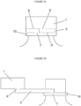
- the bottle closure assembly comprises an upper cap portion, an intermediate elongate tethering portion, and a lower retaining collar portion, where the intermediate elongate tethering portion has a first end permanently connected to at least one point of the upper cap portion and a second end permanently connected to at least one point on the lower retaining collar portion, wherein the intermediate elongate tethering portion is partially joined to a lower annular edge of the upper cap portion along a first peripheral weakening line and the intermediate elongate tethering portion is partially joined to an upper annular edge of the lower retaining collar portion along a second peripheral weakening line, wherein removal of the upper cap portion from a bottle separates the upper cap portion from the intermediate elongate tethering portion along the first peripheral weakening line and separates the lower retaining collar portion from the intermediate elongate tethering portion along the second weakening line, while maintaining a linkage between the upper cap portion and the lower retaining collar portion through the intermediate elongate
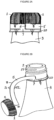
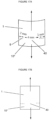
- the bottle closure assembly comprises: an upper cap portion, 1 dimensioned to reversibly cover and close a bottle opening, a lower retaining collar portion, 10 dimensioned to irreversibly engage a bottle neck, or an upper portion of a bottle, and an elongated tether portion, 5 being dimensioned as a strip which at least partially encircles a bottle neck between the upper cap portion and the lower retaining collar portion, the strip comprising a first end, a second end, an upper edge and a lower edge, the upper edge of which is in part contiguous with the upper cap portion, the lower edge of which is in part contiguous with the lower retaining collar portion, whereby removal of the upper cap portion from a bottle (by for example rotation about a threaded system on the bottle neck) separates the elongated tether portion from the upper cap portion and the lower retaining collar portion, while at the same leaving the upper cap portion attached to the lower retaining collar via the e
- the bottle closure assembly comprises: an upper cap portion, 1 dimensioned to reversibly cover and close a bottle opening, 2 a lower retaining collar portion, 10 dimensioned to irreversibly engage a bottle neck, 3 or an upper portion of a bottle, and an elongated tether portion, 5 being dimensioned as a strip which at least partially encircles a bottle neck between the upper cap portion and the lower retaining collar portion, the strip comprising a first end, 6 a second end, 7 an upper edge, 11 and a lower edge, 12, the upper edge of which is in part frangibly attached, 8 to the upper cap portion, and in part contiguous with the upper cap portion, the lower edge of which is in part frangibly attached, 9 to the lower retaining collar portion and in part contiguous with the lower retaining collar portion, whereby removal of the upper cap portion from a bottle will rupture the frangible attachments while leaving the upper cap portion attached to the lower retaining collar portion
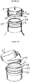
- the bottle closure assembly comprises: an upper cap portion, 1 dimensioned to reversibly cover and close a bottle opening, a lower retaining collar portion, 10 dimensioned to irreversibly engage a bottle neck, 3 or an upper portion of a bottle, and an elongated tether portion, 5 being dimensioned as a strip which at least partially encircles a bottle neck between the upper cap portion and the lower retaining collar portion, the strip having a first end, 6 a second end, 7 an upper edge, and a lower edge, the upper edge of which is in part frangibly attached to the upper cap portion by frangible elements, 20 (such as for example breakable pins), and in part contiguous with the upper cap portion, the lower edge of which is in part frangibly attached to the lower retaining collar portion by frangible elements, 20 (such as for example breakable pins) and in part contiguous with the lower retaining collar portion, whereby removal of the upper cap portion from a frangible elements, 20 (such as for example breakable pins) and
- the bottle closure assembly comprises a cap portion, 1, an elongated tether portion, 5, and a retaining collar portion, 10.
- the bottle closure assembly comprises: a cap portion, 1 a tether portion, 5 and a retaining means portion, 10 the cap portion being molded to reversibly engage and cover a bottle opening, the retaining means portion being molded to irreversibly engage a bottle neck or an upper portion of a bottle, 18 and the tether portion being molded to connect at least one point on the cap portion to at least one point on the retaining means portion, the cap portion and the retaining collar portion extending coaxially with each other, the tether portion comprising a tabbed tether strip which is integrally formed with and secured at its respective ends (6 and 7) to the cap portion and the retaining collar portion, the tether strip being joined to the cap portion and the retaining collar along a preselected length of the tether strip to be manually separated from the cap portion and the retaining collar portion by frangible elements, 20 of a preselected thickness to permit the elongated tether strip to
- the bottle closure assembly comprises: a cap portion having a top wall and a side wall, an elongated tether portion, and a retaining collar portion, the cap portion being molded to reversibly engage and cover a bottle opening, the retaining collar portion being annular and being molded to irreversibly engage a ridge or flange on a bottle neck or on an upper portion of a bottle, and the elongated tether portion being integrally molded with the cap portion and the retaining collar portion to connect at least one point on the cap side wall to at least one point on the retaining collar portion, wherein the elongated tether portion runs between the cap side wall and the retaining collar portion along the circumference of the cap portion when the cap portion is on a bottle and the elongated tether portion connects at least one point on the cap side wall to at least one point on the retaining collar portion when the cap portion is removed from a bottle.
- the bottle closure assembly comprises an upper cap portion, 1 an intermediate elongate tethering portion, 5 and a lower retaining collar portion, 10 where the intermediate elongate tethering portion has a first end permanently connected to at least one point of the upper cap portion and a second end permanently connected to at least one point on the lower retaining collar portion, wherein the intermediate elongate tethering portion is partially joined to a lower annular edge of the upper cap portion along a first peripheral weakening line defined by perforations, 25 and the intermediate elongate tethering portion is partially joined to an upper annular edge of said lower retaining collar portion along a second peripheral weakening line defined by perforations, 25 wherein removal of the upper cap portion from a bottle separates the upper cap portion from the tethering portion along the first peripheral weakening line and separates the lower retaining collar portion from the tethering portion along the second weakening line, while maintaining a linkage between
- a bottle neck 3 may have an annular groove 28, which presents a flange onto which the cap portion, 1 may reversibly engage in a snap fit arrangement.
- a bottle neck may have an outwardly extended annular flange, 29 which prevents a retaining collar portion, 10 from being removed from a bottle neck.
- the bottle closure assembly comprises a cap portion, 1, an elongated tether portion, 5, and a retaining collar portion, 10.
- the elongated tether portion connects at least one point of the cap portion at a first end, 6 to at least one point of the retaining collar portion at a second end, 7.
- the elongated tether portion may be further joined to the cap portion along a frangible connection 8.
- the elongated tether portion may be further joined to the retaining collar portion along a frangible connection 9.
- the bottle closure assembly comprises: a cap portion, the cap portion being dimensioned to cover and close a bottle opening, a retaining collar portion, and an elongated tether portion which forms an elastic connection between at least one point on the cap portion and at least one point on the retaining collar portion.
- the retaining means portion is integrally molded into a bottle, container or the like.
- the retaining collar portion is integrally molded into a bottle, container or the like.
- the elongated tether portion fixes the cap portion to the retaining collar portion which remains secured to the bottle, making it difficult to separate the cap portion from the bottle, thereby preventing its loss, while at the same time allowing rotation of the cap portion for facile removal and replacement of the same from and onto a bottle opening.
- the bottle closure assembly is made in part or in full using a polyethylene composition
- a polyethylene composition comprising: (1) 10 to 70 wt% of a first ethylene copolymer having a melt index I 2 , of less than 1.0 g/10min; and a density of from 0.920 to 0.960 g/cm 3 ; and (2) 90 to 30 wt% of a second ethylene copolymer or an ethylene homopolymer; the second ethylene copolymer or the ethylene homopolymer having a melt index I 2 , of at least 20 g/10min; and a density higher than the density of the first ethylene copolymer, but less than 0.970 g/cm 3 ; wherein the ratio (SCB1/SCB2) of the number of short chain branches per thousand carbon atoms in said first ethylene copolymer (SCB1) to the number of short chain branches per thousand carbon atoms in said second ethylene copolymer (SCB2) is greater than 0.5; and wherein the polyethylene composition has
- the cap portion, the elongated tether portion, and the retaining collar portion are all integrally molded from a polyethylene composition
- a polyethylene composition comprising: (1) 10 to 70 wt% of a first ethylene copolymer having a melt index I 2 , of less than 1.0 g/10min; and a density of from 0.920 to 0.960 g/cm 3 ; and (2) 90 to 30 wt% of a second ethylene copolymer or an ethylene homopolymer; the second ethylene copolymer or the ethylene homopolymer having a melt index I 2 , of at least 20 g/10min; and a density higher than the density of the first ethylene copolymer, but less than 0.970 g/cm 3 ; wherein the ratio (SCB1/SCB2) of the number of short chain branches per thousand carbon atoms in said first ethylene copolymer (SCB1) to the number of short chain branches per thousand carbon atoms in said second ethylene copolymer (SCB
- Suitable polyethylene compositions for use in the manufacture of part or all of the bottle closure assembly are described in more detail below.
- ethylene copolymer it is meant that the copolymer comprises both ethylene and at least one alpha-olefin comonomer.
- an "ethylene copolymer” or “polyethylene copolymer” is the product of a polymerization process, where ethylene and one or more than one alpha-olefin comonomer were deliberately added or was deliberately present as polymerizable olefins.
- ethylene homopolymer it is meant that the copolymer comprises only ethylene (or a negligible amount of an alpha-olefin comonomer).
- an "ethylene homopolymer” or “polyethylene homopolymer” is the product of a polymerization process, where only ethylene was deliberately added as a polymerizable olefin.
- homogeneous or “homogeneously branched polymer” as used herein define homogeneously branched polyethylene which has a relatively narrow composition distribution, as indicated by a relatively high composition distribution breadth index (CDBI 50 ). That is, the comonomer is randomly distributed within a given polymer chain and a substantial portion of the polymer chains have same ethylene/comonomer ratio. It is well known that metallocene catalysts and other so called “single site catalysts” incorporate comonomer more evenly than traditional Ziegler-Natta catalysts when used for catalytic ethylene copolymerization with alpha olefins.
- composition distribution breadth index (CDBI 50 ) for corresponding ethylene copolymers.
- the composition distribution of a polymer can be characterized by the short chain distribution index (SCDI) or composition distribution breadth index (CDBI 50 ).
- SCDI short chain distribution index
- CDBI 50 composition distribution breadth index
- the definition of composition distribution breadth index (CDBI 50 ) can be found in PCT publication WO 93/03093 and U.S. Pat. No. 5,206,075 .
- the CDBI 50 is conveniently determined using techniques which isolate polymer fractions based on their solubility (and hence their comonomer content). For example, temperature rising elution fractionation (TREF) as described by Wild et al. J. Poly. Sci., Poly. Phys. Ed. Vol.
- the CDBI 50 is determined by establishing the weight percentage of a copolymer sample that has a comonomer content within 50% of the median comonomer content on each side of the median.
- Ziegler-Natta catalysts produce ethylene copolymers with a CDBI 50 of less than about 50 weight %, or less than about 55 weight %, consistent with a heterogeneously branched copolymer.
- metallocenes and other single site catalysts will most often produce ethylene copolymers having a CDBI 50 of greater than about 55 weight %, or greater than about 60 weight %, consistent with a homogeneously branched copolymer.
- the polyethylene composition will comprise at least a first ethylene copolymer and a second ethylene copolymer which is different from the first ethylene polymer.
- the polyethylene composition will comprise at least a first ethylene copolymer and an ethylene homopolymer.
- the first ethylene copolymer of the polyethylene composition has a density of from about 0.920 g/cm 3 to about 0.955 g/cm 3 ; a melt index, I 2 , of less than about 0.4 g/10 min; a molecular weight distribution, M w /M n , of below about 3.0 and a weight average molecular weight, M w , that is greater than the M w of the second ethylene copolymer or the ethylene homopolymer.
- the weight average molecular weight, M w , of the first ethylene copolymer is at least 110,000 (g/mol).
- the first ethylene copolymer of the polyethylene composition has a density of from about 0.920 g/cm 3 to about 0.955 g/cm 3 ; a melt index, I 2 , of less than about 0.4 g/10 min; a molecular weight distribution, M w /M n , of below about 2.7 and a weight average molecular weight, M w , that is greater than the M w of the second ethylene copolymer or the ethylene homopolymer.
- the first ethylene copolymer is a homogeneously branched copolymer.
- the first ethylene copolymer is made with a single site catalyst, such as for example a phosphinimine catalyst.
- the comonomer (i.e. alpha-olefin) content in the first ethylene copolymer can be from about 0.05 to about 3.0 mol%.
- the comonomer content of the first ethylene polymer is determined by mathematical deconvolution methods applied to a bimodal polyethylene composition (see the Examples section).
- the comonomer in the first ethylene copolymer is one or more olefin such as but not limited to 1-butene, 1-hexene, 1-octene and the like.
- the first ethylene copolymer is a copolymer of ethylene and 1-octene.
- the short chain branching in the first ethylene copolymer can be from about 0.25 to about 15 short chain branches per thousand carbon atoms (SCB1/1000Cs). In further embodiments of the disclosure, the short chain branching in the first ethylene copolymer can be from 0.5 to 15, or from 0.5 to 12, or from 0.5 to 10, or from 0.75 to 15, or from 0.75 to 12, or from 0.75 to 10, or from 1.0 to 10, or from 1.0 to 8.0, or from 1.0 to 5, or from 1.0 to 3 branches per thousand carbon atoms (SCB1/1000Cs).
- the short chain branching is the branching due to the presence of alpha-olefin comonomer in the ethylene copolymer and will for example have two carbon atoms for a 1-butene comonomer, or four carbon atoms for a 1-hexene comonomer, or six carbon atoms for a 1-octene comonomer, etc.
- the number of short chain branches in the first ethylene copolymer is determined by mathematical deconvolution methods applied to a bimodal polyethylene composition (see the Examples section).
- the comonomer content in the first ethylene copolymer is substantially similar or approximately equal (e.g., within about ⁇ 0.01 mol%) to the comonomer content of the second ethylene copolymer (as reported, for example, in mol%).
- the comonomer content in the first ethylene copolymer is greater than comonomer content of the second ethylene copolymer (as reported for example in mol%).
- the amount of short chain branching in the first ethylene copolymer is substantially similar or approximately equal (e.g., within about ⁇ 0.05 SCB/1000Cs) to the amount of short chain branching in the second ethylene copolymer (as reported in short chain branches, SCB per thousand carbons in the polymer backbone, 1000Cs).
- the amount of short chain branching in the first ethylene copolymer is greater than the amount of short chain branching in the second ethylene copolymer (as reported in short chain branches, SCB per thousand carbons in the polymer backbone, 1000Cs).
- melt index, I 2 of the first ethylene copolymer is less than 1.0 g/10min ( ⁇ 1.0 g/10min).
- the melt index, I 2 of the first ethylene copolymer is less than 0.4 g/10min.
- the melt index of the first ethylene copolymer can in an embodiment of the disclosure be above 0.01, but below 0.4 g/10min.
- the melt index, I 2 of the first ethylene copolymer will be from 0.01 to 0.40 g/10min, or from 0.01 to 0.30 g/10min, or from 0.01 to 0.25 g/10min, or from 0.01 to 0.20 g/10min, or from 0.01 to 0.10 g/10min.
- the first ethylene copolymer has a weight average molecular weight M w of from about 110,000 to about 300,000 (g/mol). In another embodiment of the disclosure, the first ethylene copolymer has a weight average molecular weight M w of from about 110,000 to about 275,000 or from about 110,000 to about 250,000. In another embodiment of the disclosure, the first ethylene copolymer has a weight average molecular weight M w of greater than about 110,000 to less than about 250,000. In further embodiments of the disclosure, the first ethylene copolymer has a weight average molecular weight M w of from about 125,000 to about 225,000, or from about 135,000 to about 200,000.
- the first ethylene copolymer has a weight average molecular weight M w of from about 125,000 to about 275,000, or from about 125,000 to about 250,000, or from about 150,000 to about 275,000, or from about 150,000 to about 250,000, or from about 175,000 to about 250,000. In embodiments of the disclosure, the first ethylene copolymer has a M w of greater than 110,000, or greater than 125,000, or greater than 150,000, or greater than 175,000. In embodiments of the disclosure the first ethylene copolymer has a M w of greater than 110,000, or greater than 125,000, or greater than 150,000, or greater than 175,000 while at the same time being lower than 275,000, or 250,000.
- the density of the first ethylene copolymer is from 0.920 to 0.960 g/cm 3 or can be a narrower range within this range and any numbers encompassed by these ranges.
- the density of the first ethylene copolymer is from 0.920 to 0.955 g/cm 3 or can be a narrower range within this range.
- the density of the first ethylene copolymer can be from 0.925 to 0.955 g/cm 3 , or from 0.925 to 0.950 g/cm 3 , or from 0.925 to 0.945 g/cm 3 , or from 0.925 to 0.940 g/cm 3 , or from 0.925 to 0.935 g/cm 3 , or from 0.923 to 0.945 g/cm 3 , or from 0.923 to 0.940 g/cm 3 , or from 0.923 to 0.935 g/cm 3 , or from 0.927 to 0.945 g/cm 3 , or from 0.927 to 0.940 g/cm 3 , or from 0.927 to 0.935 g/cm 3 .
- the first ethylene copolymer has a molecular weight distribution M w /M n of ⁇ 3.0, or ⁇ 2.7, or ⁇ 2.7, or ⁇ 2.5, or ⁇ 2.5, or ⁇ 2.3, or from 1.8 to 2.3.
- the M w /M n value of the first ethylene copolymer can in an embodiment of the disclosure be estimated by a de-convolution of a GPC profile obtained for a bimodal polyethylene composition of which the first ethylene copolymer is a component.
- the density and the melt index, I 2 , of the first ethylene copolymer can be estimated from GPC (gel permeation chromatography) and GPC-FTIR (gel permeation chromatography with Fourier transform infra-red detection) experiments and deconvolutions carried out on the bimodal polyethylene composition (see the Examples section).
- the first ethylene copolymer of the polyethylene composition is a homogeneously branched ethylene copolymer having a weight average molecular weight, M W , of at least 110,000; a molecular weight distribution, M w /M n , of less than 2.7 and a density of from 0.920 to 0.948 g/cm 3 .
- the first ethylene copolymer is homogeneously branched ethylene copolymer and has a CDBI 50 of greater than about 50%, or greater than about 55% by weight. In further embodiments of the disclosure, the first ethylene copolymer has a CDBI of greater than about 60%, or greater than about 65%, or greater than about 70%, or greater than about 75%, or greater than about 80% by weight. In the present disclosure, the first ethylene copolymer comprises from 10 to 70 weight percent (wt%) of the weight of the polyethylene composition (e.g. 10 to 70 weight percent of the total weight of the first ethylene copolymer and the second ethylene copolymer or the ethylene homopolymer).
- the first ethylene copolymer can comprise from 20 to 60 weight percent (wt%) of the weight of the polyethylene composition (e.g. 20 to 60 weight percent of the total weight of the first ethylene copolymer and the second ethylene copolymer or the ethylene homopolymer). In an embodiment of the disclosure, the first ethylene copolymer can comprise from 30 to 60 weight percent (wt%) of the weight of the polyethylene composition (i.e. e.g. 30 to 60 weight percent of the total weight of the first ethylene copolymer and the second ethylene copolymer or the ethylene homopolymer).
- the first ethylene copolymer can comprise from 40 to 50 weight percent (wt%) of the weight of the polyethylene composition (e.g. 40 to 50 weight percent of the total weight of the first ethylene copolymer and the second ethylene copolymer or the ethylene homopolymer).
- the second ethylene copolymer has a density which is higher than the density of the first ethylene copolymer.
- the second ethylene copolymer of the polyethylene composition has a density equal or below 0.967 g/cm 3 but which is higher than the density of the first ethylene copolymer; a melt index, I 2 , of from about 100 to 10,000 g/10min; a molecular weight distribution, M w /M n , of below about 3.0 and a weight average molecular weight M w that is less than the M w of the first ethylene copolymer.
- the weight average molecular weight, M w of the second ethylene copolymer will be below 45,000.
- the second ethylene copolymer of the polyethylene composition has a density equal to or below 0.967 g/cm 3 but which is higher than the density of the first ethylene copolymer; a melt index, I 2 , of from about 500 to about 20,000 g/10min; a molecular weight distribution, M w /M n , of below about 2.7, and a weight average molecular weight M w that is less than the M w of the first ethylene copolymer.
- the second ethylene copolymer is homogeneously branched copolymer.
- the second ethylene copolymer is made with a single site catalyst, such as for example a phosphinimine catalyst.
- the comonomer content in the second ethylene copolymer can be from about 0.05 to about 3 mol% as measured by 13 C NMR, or FTIR or GPC-FTIR methods.
- the comonomer content of the second ethylene polymer can also be determined by mathematical deconvolution methods applied to a bimodal polyethylene composition (see the Examples section).
- the comonomer content in the second ethylene copolymer can be from about 0.01 to about 3 mol%, or from about 0.03 to about 3 mol% as measured by 13 C NMR, or FTIR or GPC-FTIR methods.
- the comonomer content of the second ethylene polymer can also be determined by mathematical deconvolution methods applied to a bimodal polyethylene composition (see the Examples section).
- the comonomer in the second ethylene copolymer is one or more alpha olefin such as but not limited to 1-butene, 1-hexene, 1-octene and the like.
- the second ethylene copolymer is a copolymer of ethylene and 1-octene.
- the short chain branching in the second ethylene copolymer can be from about 0.25 to about 15 short chain branches per thousand carbon atoms (SCB2/1000Cs). In further embodiments of the disclosure, the short chain branching in the second ethylene copolymer can be from 0.25 to 12, or from 0.25 to 8, or from 0.25 to 5, or from 0.25 to 3, or from 0.25 to 2 branches per thousand carbon atoms (SCB2/1000Cs).
- the short chain branching is the branching due to the presence of alpha-olefin comonomer in the ethylene copolymer and will for example have two carbon atoms for a 1-butene comonomer, or four carbon atoms for a 1-hexene comonomer, or six carbon atoms for a 1-octene comonomer, etc.
- the number of short chain branches in the second ethylene copolymer can be measured by 13 C NMR, or FTIR or GPC-FTIR methods. Alternatively, the number of short chain branches in the second ethylene copolymer can be determined by mathematical deconvolution methods applied to a bimodal polyethylene composition (see the Examples section).
- the comonomer is one or more suitable alpha olefin such as but not limited to 1-butene, 1-hexene, 1-octene and the like, with 1-octene being preferred, in some embodiments.
- the short chain branching in the second ethylene copolymer can be from about 0.15 to about 15 short chain branches per thousand carbon atoms (SCB2/1000Cs). In further embodiments of the disclosure, the short chain branching in the second ethylene copolymer can be from 0.15 to 12, or from 0.15 to 8, or from 0.15 to 5, or from 0.15 to 3, or from 0.15 to 2 branches per thousand carbon atoms (SCB2/1000Cs).
- the short chain branching is the branching due to the presence of alpha-olefin comonomer in the ethylene copolymer and will for example have two carbon atoms for a 1-butene comonomer, or four carbon atoms for a 1-hexene comonomer, or six carbon atoms for a 1-octene comonomer, etc.
- the short chain branching in the second ethylene copolymer can be from about 0.05 to about 12 short chain branches per thousand carbon atoms (SCB1/1000Cs).
- the short chain branching in the second ethylene copolymer can be from 0.05 to 7.5, or from 0.05 to 5.0, or from 0.05 to 2.5, or from 0.05 to 1.5, or from 0.1 to 12, or from 0.1 to 10, or from 0.1 to 7.5, or from 0.1 to 5.0, or from 0.1 to 2.5, or from 0.1 to 2.0, or from 0.1 to 1.0 branches per thousand carbon atoms (SCB1/1 000Cs).
- the short chain branching in the second ethylene copolymer can be from about 0.05 to about 10 short chain branches per thousand carbon atoms (SCB1/1000Cs).
- the short chain branching in the second copolymer can be from 0.05 to 7.5, or from 0.05 to 5.0, or from 0.05 to 2.5, or from 0.05 to 1.5, or from 0.1 to 12, or from 0.1 to 10, or from 0.1 to 7.5, or from 0.1 to 5.0, or from 0.1 to 2.5, or from 0.1 to 2.0, or from 0.1 to 1.0 branches per thousand carbon atoms (SCB1/1000Cs).
- the comonomer content in the second ethylene copolymer is substantially similar or approximately equal (e.g., within about ⁇ 0.01 mol%) to the comonomer content of the first ethylene copolymer (as reported, for example, in mol%).
- the comonomer content in the second ethylene copolymer is less than the comonomer content of the first ethylene copolymer (as reported for example in mol%).
- the amount of short chain branching in the second ethylene copolymer is substantially similar or approximately equal (e.g. within about ⁇ 0.05 SCB/1000C) to the amount of short chain branching in the first ethylene copolymer (as reported in short chain branches, SCB per thousand carbons in the polymer backbone, 1000Cs).
- the amount of short chain branching in the second ethylene copolymer is less than the amount of short chain branching in the first ethylene copolymer (as reported in short chain branches, SCB per thousand carbons in the polymer backbone, 1000Cs).
- the density of the second ethylene copolymer is less than 0.970 g/cm 3 .
- the density of the second ethylene copolymer is less than 0.967 g/cm 3 .
- the density of the second ethylene copolymer in another embodiment of the disclosure is less than 0.966 g/cm 3 .
- the density of the second ethylene copolymer is less than 0.965 g/cm 3 .
- the density of the second ethylene copolymer is less than 0.964 g/cm 3 .
- the density of the second ethylene copolymer is less than 0.963 g/cm 3 .
- the density of the second ethylene copolymer is less than 0.962 g/cm 3 .
- the density of the second ethylene copolymer is higher than the density of the first ethylene copolymer, but is less than 0.970 g/cm 3 .
- the density of the second ethylene copolymer is higher than the density of the first ethylene copolymer, but is less than 0.967 g/cm 3 .
- the density of the second ethylene copolymer in another embodiment of the disclosure is higher than the density of the first ethylene copolymer, but is less than 0.966 g/cm 3 .
- the density of the second ethylene copolymer is higher than the density of the first ethylene copolymer, but is less than 0.965 g/cm 3 .
- the density of the second ethylene copolymer is higher than the density of the first ethylene copolymer, but is less than 0.964 g/cm 3 .
- the density of the second ethylene copolymer is higher than the density of the first ethylene copolymer, but is less than 0.963 g/cm 3 . In another embodiment of the disclosure, the density of the second ethylene copolymer is higher than the density of the first ethylene copolymer, but is less than 0.962 g/cm 3 .
- the density of the second ethylene copolymer is from 0.952 to 0.967 g/cm 3 or can be a narrower range within this range.
- the density of the second ethylene copolymer may in embodiments of the disclosure be from 0.952 to 0.966 g/cm 3 , 0.952 to 0.965 g/cm 3 , or from 0.952 to 0.964 g/cm 3 , or from 0.952 to 0.963 g/cm 3 , or from 0.954 to 0.963 g/cm 3 , or from 0.954 to 0.964 g/cm 3 , or from 0.956 to 0.964 g/cm 3 , or from 0.952 to less than 0.965 g/cm 3 , or from 0.954 to less than 0.965 g/cm 3 .
- the second ethylene copolymer has a weight average molecular weight M w of less than about 45,000, or less than about 40,000 or less than about 35,000. In another embodiment of the disclosure, the second ethylene copolymer has a weight average molecular weight M w of from about 7,500 to about 35,000. In further embodiments of the disclosure, the second ethylene copolymer has a weight average molecular weight M w of from about 9,000 to about 35,000, or from about 10,000 to about 35,000, or from about 12,500 to about 30,000, or from about 10,000 to about 25,000, or from about 10,000 to about 20,000.
- the second ethylene copolymer has a weight average molecular weight M w of less than 25,000. In another embodiment of the disclosure, the second ethylene copolymer has a weight average molecular weight M w of from about 7,500 to about 23,000. In further embodiments of the disclosure, the second ethylene copolymer has a weight average molecular weight M w of from about 9,000 to about 22,000, or from about 10,000 to about 17,500, or from about 7,500 to about 17,500.
- the second ethylene copolymer has a weight average molecular weight M w of from about 3,500 to about 25,000, or from about 5,000 to about 20,000, or from about 7,500 to about 17,500, or from about 5,000 to about 15,000, or from about 5,000 to about 17,500, or from about 7,500 to about 15,000 or from about 7,500 to about 12,500.
- the second ethylene copolymer has a weight average molecular weight M w of from about 9,000 to about 22,000, or from about 10,000 to about 17,500, or from about 7,500 to 17,500.
- the second ethylene copolymer has a molecular weight distribution, M w /M n of ⁇ 3.0, or ⁇ 2.7, or ⁇ 2.7, or ⁇ 2.5, or ⁇ 2.5, or ⁇ 2.3, or from 1.8 to 2.3.
- the Mw/Mn value of the second ethylene copolymer can in an embodiment of the disclosure be estimated by a de-convolution of a GPC profile obtained for a bimodal polyethylene composition of which the first ethylene copolymer is a component.
- the melt index I 2 of the second ethylene copolymer is at least 20 g/10min.
- the melt index I 2 of the second ethylene copolymer can be from 20 to 10,000 g/10min. In another embodiment of the disclosure, the melt index I 2 of the second ethylene copolymer can be from 100 to 10,000 g/10min. In yet another embodiment of the disclosure, the melt index I 2 of the second ethylene copolymer can be from 1,000 to 7000 g/10min. In yet another embodiment of the disclosure, the melt index I 2 of the second ethylene copolymer can be from 1,200 to 10,000 g/10min. In yet another embodiment of the disclosure, the melt index I 2 of the second ethylene copolymer can be from 1,500 to 10,000 g/10min. In yet another embodiment of the disclosure, the melt index I 2 of the second ethylene copolymer can be greater than 1,500, but less than 7,000 g/10min.
- the melt index I 2 of the second ethylene copolymer can be from 50 to 20,000 g/10min. In another embodiment of the disclosure, the melt index I 2 of the second ethylene copolymer can be from 250 to 20,000 g/10min. In another embodiment of the disclosure, the melt index I 2 of the second ethylene copolymer can be from 500 to 20,000 g/10min. In another embodiment of the disclosure, the melt index I 2 of the second ethylene copolymer can be from 1,000 to 20,000 g/10min. In yet another embodiment of the disclosure, the melt index I 2 of the second ethylene copolymer can be from 1,500 to 20,000 g/10min.
- the melt index I 2 of the second ethylene copolymer can be from 1,500 to 10,000 g/10min. In yet another embodiment of the disclosure, the melt index I 2 of the second ethylene copolymer can be from 1,500 to 7,000 g/10min. In yet another embodiment of the disclosure, the melt index I 2 of the second ethylene copolymer can be greater than 1,500, but less than 7,000 g/10min. In yet another embodiment of the disclosure, the melt index I 2 of the second ethylene copolymer can be greater than 1,500, but less than 5000 g/10min. In yet another embodiment of the disclosure, the melt index I 2 of the second ethylene copolymer can be greater than 1000, but less than 3500 g/10min.
- the melt index I 2 of the second ethylene copolymer can be from 250 to 20,000 g/10min. In another embodiment of the disclosure, the melt index I 2 of the second ethylene copolymer can be from 500 to 20,000 g/10min. In another embodiment of the disclosure, the melt index I 2 of the second ethylene copolymer can be from greater than 750 to 20,000 g/10min.
- the melt index I 2 of the second ethylene copolymer can be from 1,000 to 20,000 g/10min, or from 1,500 to 20,000 g/10min, or from 250 to 15,000 g/10min, or from 250 to 10,000 g/10min or from 500 to 17,500 g/10min, or from 500 to 15,000 g/10min, or from 1,500 to 15,000 g/10min.
- the melt index I 2 of the second ethylene copolymer can be from 1,200 to 10,000 g/10min.
- the melt index I 2 of the second ethylene copolymer can be from 1,500 to 10,000 g/10min.
- the melt index I 2 of the second ethylene copolymer can be greater than 1,500, but less than 7,000 g/10min.
- the melt index I 2 of the second ethylene copolymer is greater than 200 g/10min. In an embodiment of the disclosure, the melt index I 2 of the second ethylene copolymer is greater than 250 g/10min. In an embodiment of the disclosure, the melt index I 2 of the second ethylene copolymer is greater than 500 g/10min. In an embodiment of the disclosure, the melt index I 2 of the second ethylene copolymer is greater than 650 g/10min. In an embodiment of the disclosure, the melt index I 2 of the second ethylene copolymer is greater than 1000 g/10min. In an embodiment of the disclosure, the melt index I 2 of the second ethylene copolymer is greater than 1,200 g/10min. In an embodiment of the disclosure, the melt index I 2 of the second ethylene copolymer is greater than 1,500 g/10min. In an embodiment of the disclosure, the melt index I 2 of the second ethylene copolymer is greater than 1,750 g/10min.
- the density and the melt index, I 2 , of the second ethylene copolymer can be estimated from GPC and GPC-FTIR experiments and deconvolutions carried out on a bimodal polyethylene composition (see the below Examples section).
- the second ethylene copolymer of the polyethylene composition is a homogeneous ethylene copolymer having a weight average molecular weight, M W , of at most 45000; a molecular weight distribution, M w /M n , of less than 2.7 and a density higher than the density of said first ethylene copolymer, but less than 0.967 g/cm 3 .
- the second ethylene copolymer is homogeneously branched ethylene copolymer and has a CDBI 50 of greater than about 50 weight%, or of greater than about 55 weight%. In further embodiments of the disclosure, the second ethylene copolymer has a CDBI 50 of greater than about 60 weight%, or greater than about 65 weight%, or greater than about 70 weight%, or greater than about 75 weight %, or greater than about 80 weight %. In the present disclosure, the second ethylene copolymer comprises from 90 to 30 weight percent (wt%) of the of the polyethylene composition (e.g. 90 to 30 weight percent of the total weight of the first ethylene copolymer and the second ethylene copolymer).
- the second ethylene copolymer can comprise from 80 to 40 weight percent (wt%) of the weight of the polyethylene composition (e.g. 80 to 40 weight percent of the total weight of the first ethylene copolymer and the second ethylene copolymer). In an embodiment of the disclosure, the second ethylene copolymer can comprise from 70 to 40 weight percent (wt%) of the weight of the polyethylene composition (e.g. 70 to 40 weight percent of the total weight of the first ethylene copolymer and the second ethylene copolymer). In an embodiment of the disclosure, the second ethylene copolymer can comprise from 60 to 50 weight percent (wt%) of the weight of the polyethylene composition (e.g. 60 to 50 weight percent of the total weight of the first ethylene copolymer and the second ethylene copolymer).
- the second ethylene copolymer has a density which is higher than the density of the first ethylene copolymer, but less than about 0.037 g/cm 3 higher than the density of the first ethylene copolymer. In an embodiment of the disclosure, the second ethylene copolymer has a density which is higher than the density of the first ethylene copolymer, but less than about 0.036 g/cm 3 higher than the density of the first ethylene copolymer. In an embodiment of the disclosure, the second ethylene copolymer has a density which is higher than the density of the first ethylene copolymer, but less than about 0.035 g/cm 3 higher than the density of the first ethylene copolymer.
- the second ethylene copolymer has a density which is higher than the density of the first ethylene copolymer, but less than about 0.034 g/cm 3 higher than the density of the first ethylene copolymer. In an embodiment of the disclosure, the second ethylene copolymer has a density which is higher than the density of the first ethylene copolymer, but less than about 0.033 g/cm 3 higher than the density of the first ethylene copolymer. In an embodiment of the disclosure, the second ethylene copolymer has a density which is higher than the density of the first ethylene copolymer, but less than about 0.032 g/cm 3 higher than the density of the first ethylene copolymer.
- the second ethylene copolymer has a density which is higher than the density of the first ethylene copolymer, but less than about 0.031 g/cm 3 higher than the density of the first ethylene copolymer. In still another embodiment of the disclosure, the second ethylene copolymer has a density which is higher than the density of the first ethylene copolymer, but less than about 0.030 g/cm 3 higher than the density of the first ethylene copolymer.
- the I 2 of the second ethylene copolymer is at least 20 times, or at least 100 times, or at least 1000 times, or at least 10,000, or at least 50,000 times the I 2 of the first ethylene copolymer.
- the ethylene homopolymer has a density which is higher than the density of the first ethylene copolymer.
- the ethylene homopolymer of the polyethylene composition has a density equal to or below 0.967 g/cm 3 but which is higher than the density of the first ethylene copolymer; a melt index, I 2 , of from about 100 to 10,000 g/10min; a molecular weight distribution, M w /M n , of below about 3.0 and a weight average molecular weight M w that is less than the M w of the first ethylene copolymer.
- the weight average molecular weight, M w of the ethylene homopolymer will be below 45,000.
- the ethylene homopolymer of the polyethylene composition has a density equal to or below 0.967 g/cm 3 but which is higher than the density of the first ethylene copolymer; a melt index, I 2 , of from about 500 to about 20,000 g/10min; a molecular weight distribution, M w /M n , of below about 2.7, and a weight average molecular weight M w that is less than the M w of the first ethylene copolymer.
- the ethylene homopolymer is made with a single site catalyst, such as for example a phosphinimine catalyst.
- the density of the ethylene homopolymer is less than 0.970 g/cm 3 .
- the density of the ethylene homopolymer is less than 0.967 g/cm 3 .
- the density of the ethylene homopolymer in another embodiment of the disclosure is less than 0.966 g/cm 3 .
- the density of the ethylene homopolymer is less than 0.965 g/cm 3 .
- the density of the ethylene homopolymer is less than 0.964 g/cm 3 .
- the density of the ethylene homopolymer is less than 0.963 g/cm 3 .
- the density of the ethylene homopolymer is less than 0.962 g/cm 3 .
- the density of the ethylene homopolymer is higher than the density of the first ethylene copolymer, but is less than 0.970 g/ cm 3 .
- the density of the ethylene homopolymer is higher than the density of the first ethylene copolymer, but is less than 0.967 g/cm 3 .
- the density of the ethylene homopolymer in another embodiment of the disclosure is higher than the density of the first ethylene copolymer, but is less than 0.966 g/cm 3 .
- the density of the ethylene homopolymer is higher than the density of the first ethylene copolymer, but is less than 0.965 g/cm 3 .
- the density of the ethylene homopolymer is higher than the density of the first ethylene copolymer, but is less than 0.964 g/cm 3 .
- the density of the ethylene homopolymer is higher than the density of the first ethylene copolymer, but is less than 0.963 g/cm 3 . In another embodiment of the disclosure, the density of the ethylene homopolymer is higher than the density of the first ethylene copolymer, but is less than 0.962 g/cm 3 .
- the density of the ethylene homopolymer is from 0.952 to 0.967 g/cm 3 or can be a narrower range within this range.
- the density of the ethylene homopolymer may in embodiments of the disclosure be from 0.952 to 0.966 g/cm 3 , 0.952 to 0.965 g/cm 3 , or from 0.952 to 0.964 g/cm 3 , or from 0.952 to 0.963 g/cm 3 , or from 0.954 to 0.963 g/cm 3 , or from 0.954 to 0.964 g/cm 3 , or from 0.956 to 0.964 g/cm 3 , or from 0.952 to less than 0.965 g/cm 3 , or from 0.954 to less than 0.965 g/cm 3 .
- the ethylene homopolymer has a weight average molecular weight M w of less than about 45,000, or less than about 40,000 or less than about 35,000. In another embodiment of the disclosure, the ethylene homopolymer has a weight average molecular weight M w of from about 7,500 to about 35,000. In further embodiments of the disclosure, the ethylene homopolymer has a weight average molecular weight M w of from about 9,000 to about 35,000, or from about 10,000 to about 35,000, or from about 12,500 to about 30,000, or from about 10,000 to about 25,000, or from about 10,000 to about 20,000.
- the ethylene homopolymer has a weight average molecular weight M w of less than 25,000. In another embodiment of the disclosure, the ethylene homopolymer has a weight average molecular weight M w of from about 7,500 to about 23,000. In further embodiments of the disclosure, the ethylene homopolymer has a weight average molecular weight M w of from about 9,000 to about 22,000, or from about 10,000 to about 17,500, or from about 7,500 to about 17,500.
- the ethylene homopolymer has a weight average molecular weight M w of from about 3,500 to about 25,000, or from about 5,000 to about 20,000, or from about 7,500 to about 17,500, or from about 5,000 to about 15,000, or from about 5,000 to about 17,500, or from about 7,500 to about 15,000 or from about 7,500 to about 12,500. In further embodiments of the disclosure, the ethylene homopolymer has a weight average molecular weight M w of from about 9,000 to about 22,000, or from about 10,000 to about 17,500, or from about 7,500 to 17,500.
- the ethylene homopolymer has a molecular weight distribution, M w /M n of ⁇ 3.0, or ⁇ 2.7, or ⁇ 2.7, or ⁇ 2.5, or ⁇ 2.5, or ⁇ 2.3, or from 1.8 to 2.3.
- the Mw/Mn value of the ethylene homopolymer can in an embodiment of the disclosure be estimated by a de-convolution of a GPC profile obtained for a bimodal polyethylene composition of which the first ethylene copolymer is a component.
- the melt index I 2 of the ethylene homopolymer is at least 20 g/10min.
- the melt index I 2 of the ethylene homopolymer can be from 20 to 10,000 g/10min. In another embodiment of the disclosure, the melt index I 2 of the ethylene homopolymer can be from 100 to 10,000 g/10min. In yet another embodiment of the disclosure, the melt index I 2 of the ethylene homopolymer can be from 1,000 to 7,000 g/10min. In yet another embodiment of the disclosure, the melt index I 2 of the ethylene homopolymer can be from 1,200 to 10,000 g/10min. In yet another embodiment of the disclosure, the melt index I 2 of the ethylene homopolymer can be from 1,500 to 10,000 g/10min. In yet another embodiment of the disclosure, the melt index I 2 of the ethylene homopolymer can be greater than 1,500, but less than 7,000 g/10min.
- the melt index I 2 of the ethylene homopolymer can be from 50 to 20,000 g/10min. In another embodiment of the disclosure, the melt index I 2 of the ethylene homopolymer can be from 250 to 20,000 g/10min. In another embodiment of the disclosure, the melt index I 2 of the ethylene homopolymer can be from 500 to 20,000 g/10min. In another embodiment of the disclosure, the melt index I 2 of the ethylene homopolymer can be from 1000 to 20,000 g/10min. In yet another embodiment of the disclosure, the melt index I 2 of the ethylene homopolymer can be from 1,500 to 20,000 g/10min.
- the melt index I 2 of the ethylene homopolymer can be from 1,500 to 10,000 g/10min. In yet another embodiment of the disclosure, the melt index I 2 of the ethylene homopolymer can be from 1,500 to 7,000 g/10min. In yet another embodiment of the disclosure, the melt index I 2 of the ethylene homopolymer can be greater than 1,500, but less than 7,000 g/10min. In yet another embodiment of the disclosure, the melt index I 2 of the ethylene homopolymer can be greater than 1,500, but less than 5,000 g/10min. In yet another embodiment of the disclosure, the melt index I 2 of the ethylene homopolymer can be greater than 1,000, but less than 3,500 g/10min.
- the melt index I 2 of the ethylene homopolymer can be from 250 to 20,000 g/10min. In another embodiment of the disclosure, the melt index I 2 of the ethylene homopolymer can be from 500 to 20,000 g/10min. In another embodiment of the disclosure, the melt index I 2 of the ethylene homopolymer can be from greater than 750 to 20,000 g/10min.
- the melt index I 2 of the ethylene homopolymer can be from 1,000 to 20,000 g/10min, or from 1,500 to 20,000 g/10min, or from 250 to 15,000 g/10min, or from 250 to 10,000 g/10min or from 500 to 17,500 g/10min, or from 500 to 15,000 g/10min, or from 1,500 to 15,000 g/10min.
- the melt index I 2 of the ethylene homopolymer can be from 1,200 to 10,000 g/10min.
- the melt index I 2 of the ethylene homopolymer can be from 1,500 to 10,000 g/10min.
- the melt index I 2 of the ethylene homopolymer can be greater than 1,500, but less than 7,000 g/10min.
- the melt index I 2 of the ethylene homopolymer is greater than 200 g/10min. In an embodiment of the disclosure, the melt index I 2 of the ethylene homopolymer is greater than 250 g/10min. In an embodiment of the disclosure, the melt index I 2 of the ethylene homopolymer is greater than 500 g/10min. In an embodiment of the disclosure, the melt index I 2 of the ethylene homopolymer is greater than 650 g/10min. In an embodiment of the disclosure, the melt index I 2 of the ethylene homopolymer is greater than 1000 g/10min. In an embodiment of the disclosure, the melt index I 2 of the ethylene homopolymer is greater than 1,200 g/10min. In an embodiment of the disclosure, the melt index I 2 of the ethylene homopolymer is greater than 1,500 g/10min. In an embodiment of the disclosure, the melt index I 2 of the ethylene homopolymer is greater than 1,750 g/10min.
- the density and the melt index, I 2 , of the ethylene homopolymer can be estimated from GPC and GPC-FTIR experiments and deconvolutions carried out on a bimodal polyethylene composition (see the below Examples section).
- the ethylene homopolymer of the polyethylene composition is a homogeneous ethylene copolymer having a weight average molecular weight, M W , of at most 45000; a molecular weight distribution, M w /M n , of less than 2.7 and a density higher than the density of said first ethylene copolymer, but less than 0.967 g/cm 3 .
- the ethylene homopolymer comprises from 90 to 30 weight percent (wt%) of the of the polyethylene composition (e.g. 90 to 30 weight percent of the total weight of the first ethylene copolymer and the ethylene homopolymer).
- the ethylene homopolymer can comprise from 80 to 40 weight percent (wt%) of the weight of the polyethylene composition (e.g. 80 to 40 weight percent of the total weight of the first ethylene copolymer and the ethylene homopolymer).
- the ethylene homopolymer can comprise from 70 to 40 weight percent (wt%) of the weight of the polyethylene composition (i.e. e.g.
- the ethylene homopolymer can comprise from 60 to 50 weight percent (wt%) of the weight of the polyethylene composition (e.g. 60 to 50 weight percent of the total weight of the first ethylene copolymer and the ethylene homopolymer).
- the ethylene homopolymer has a density which is higher than the density of the first ethylene copolymer, but less than about 0.037 g/cm 3 higher than the density of the first ethylene copolymer. In an embodiment of the disclosure, the ethylene homopolymer has a density which is higher than the density of the first ethylene copolymer, but less than about 0.036 g/ cm 3 higher than the density of the first ethylene copolymer. In an embodiment of the disclosure, the ethylene homopolymer has a density which is higher than the density of the first ethylene copolymer, but less than about 0.035 g/cm 3 higher than the density of the first ethylene copolymer.
- the ethylene homopolymer has a density which is higher than the density of the first ethylene copolymer, but less than about 0.034 g/cm 3 higher than the density of the first ethylene copolymer. In an embodiment of the disclosure, the ethylene homopolymer has a density which is higher than the density of the first ethylene copolymer, but less than about 0.033 g/cm 3 higher than the density of the first ethylene copolymer. In an embodiment of the disclosure, the ethylene homopolymer has a density which is higher than the density of the first ethylene copolymer, but less than about 0.032 g/cm 3 higher than the density of the first ethylene copolymer.
- the ethylene homopolymer has a density which is higher than the density of the first ethylene copolymer, but less than about 0.031 g/cm 3 higher than the density of the first ethylene copolymer. In still another embodiment of the disclosure, the ethylene homopolymer has a density which is higher than the density of the first ethylene copolymer, but less than about 0.030 g/cm 3 higher than the density of the first ethylene copolymer.
- the I 2 of the ethylene homopolymer is at least 20 times, or at least 100 times, or at least 1,000 times, or at least 10,000, or at least 50,000 times the I 2 of the first ethylene copolymer.
- the polyethylene composition has a broad, bimodal or multimodal molecular weight distribution.
- the polyethylene composition will comprise a first ethylene copolymer and a second ethylene copolymer or an ethylene homopolymer, which are of different weight average molecular weight (M w ) and/or melt index, I 2 than the first ethylene copolymer
- the polyethylene composition will minimally comprise a first ethylene copolymer and a second ethylene copolymer (as defined above) and the ratio (SCB1/SCB2) of the number of short chain branches per thousand carbon atoms in the first ethylene copolymer (i.e., SCB1) to the number of short chain branches per thousand carbon atoms in the second ethylene copolymer (i.e., SCB2) will be greater than 0.5 (i.e., SCB1 / SCB2 > 0.5).
- the polyethylene composition will minimally comprise a first ethylene copolymer and an ethylene homopolymer (as defined above).
- the ratio of the short chain branching in the first ethylene copolymer (SCB1) to the short chain branching in the second ethylene copolymer (SCB2) is at least 0.60. In an embodiment of the disclosure, the ratio of the short chain branching in the first ethylene copolymer (SCB1) to the short chain branching in the second ethylene copolymer (SCB2) is at least 0.75. In another embodiment of the disclosure, the ratio of the short chain branching in the first ethylene copolymer (SCB1) to the short chain branching in the second ethylene copolymer (SCB2) is at least 1.0.
- the ratio of the short chain branching in the first ethylene copolymer (SCB1) to the short chain branching in the second ethylene copolymer (SCB2) is at greater than 1.10. In yet another embodiment of the disclosure, the ratio of the short chain branching in the first ethylene copolymer (SCB1) to the short chain branching in the second ethylene copolymer (SCB2) is at least 1.25.
- the ratio of the short chain branching in the first ethylene copolymer (SCB1) to the short chain branching in the second ethylene copolymer (SCB2) is at least 1.5, or at least 2.0, or at least 2.5, or at least 3.0, or at least 3.5, or at least 4.0 or at least 4.5.
- the ratio of the short chain branching in the first ethylene copolymer (SCB1) to the short chain branching in the second ethylene copolymer (SCB2) will be greater than 0.5, but less than 1.0.
- the ratio (SCB1/SCB2) of the short chain branching in the first ethylene copolymer (SCB1) to the short chain branching in the second ethylene copolymer (SCB2) will be from 1.0 to 12.0, or from 1.0 to 10, or from 1.0 to 7.0, or from 1.0 to 5.0, or from 1.0 to 3.0.
- the ratio (SCB1/SCB2) of the short chain branching in the first ethylene copolymer (SCB1) to the short chain branching in the second ethylene copolymer (SCB2) will be from 1.0 to 15.0, or from 2.0 to 12.0, or from 2.5 to 12.0, or from 3.0 to 12.0, or from 3.5 to 12.0.
- the polyethylene composition has a bimodal molecular weight distribution.
- the term "bimodal" means that the polyethylene composition comprises at least two components, one of which has a lower weight average molecular weight and a higher density and another of which has a higher weight average molecular weight and a lower density.
- a bimodal or multimodal polyethylene composition can be identified by using gel permeation chromatography (GPC).
- GPC gel permeation chromatography
- the GPC chromatograph will exhibit two or more component ethylene copolymers, where the number of component ethylene copolymers corresponds to the number of discernible peaks.
- One or more component ethylene copolymers may also exist as a hump, shoulder or tail relative to the molecular weight distribution of the other ethylene copolymer component.
- the polyethylene composition has a density of greater than or equal to 0.949 g/cm 3 , as measured according to ASTM D792; a melt index, I 2 , of from about 0.4 to about 5.0 g/10min, as measured according to ASTM D1238 (when conducted at 190°C, using a 2.16 kg weight); a molecular weight distribution, M w /M n , of from about 3 to about 11, a Z-average molecular weight, M z of less than 400,000, a stress exponent of less than 1.50 and an ESCR Condition B at 10% IGEPAL and 50°C of at least 20 hours.
- the polyethylene composition of the current disclosure has a density of greater than or equal to 0.949 g/cm 3 , as measured according to ASTM D792; a melt index, I 2 , of from about 0.2 to about 5.0 g/10min, as measured according to ASTM D1238 (when conducted at 190°C, using a 2.16 kg weight); a molecular weight distribution, M w /M n , of from about 6 to about 13, a Z-average molecular weight, M z of less than 450,000, a stress exponent of less than 1.50 and an ESCR Condition B at 10% IGEPAL and 50°C of at least 200 hours.
- the polyethylene composition has a comonomer content of less than 0.75 mol%, or less than 0.70 mol%, or less than 0.65 mol%, or less than 0.60 mol%, or less than 0.55 mol% as measured by FTIR or 13 C NMR methods, with 13 C NMR being preferred, where the comonomer is one or more suitable alpha olefins such as but not limited to 1-butene, 1-hexene, 1-octene and the like.
- the polyethylene composition has a comonomer content of from 0.1 to 0.75 mol%, or from 0.20 to 0.55 mol%, or from 0.25 to 0.50 mol%.
- the polyethylene composition has a density of at least 0.949 g/cm 3 .
- the polyethylene composition has a density of > 0.949 g/cm 3 , or ⁇ 0.950 g/cm 3 , or > 0.950 g/cm 3 , or ⁇ 0.953 g/cm 3 , or ⁇ 0.955 g/cm 3 , or > 0.955 g/cm 3 .
- the polyethylene composition has a density in the range of from 0.949 to 0.969 g/cm 3 .
- the polyethylene composition has a density in the range of from 0.949 to 0.960 g/cm 3 .
- the polyethylene composition has a density in the range of from 0.949 to 0.959 g/cm 3 .
- the polyethylene composition has a density in the range of from 0.949 to 0.957 g/cm 3 .
- the polyethylene composition has a density in the range of from 0.949 to 0.956 g/cm 3 .
- the polyethylene composition has a density in the range of from 0.949 to 0.955 g/cm 3 .
- the polyethylene composition has a density in the range of from 0.950 to 0.955 g/cm 3 .
- the polyethylene composition has a density in the range of from 0.951 to 0.957 g/cm 3 .
- the polyethylene composition has a density in the range of from 0.951 to 0.955 g/cm 3 .
- the polyethylene composition has a melt index, I 2 , of from 0.1 to 4.0 g/10 min according to ASTM D1238 (when conducted at 190°C, using a 2.16 kg weight) including narrower ranges within this range and all the numbers within this range.
- the polyethylene composition has a melt index, I 2 , of from 0.3 to 4.0 g/10min, or from 0.4 to 3.5 g/10min, or from 0.4 to 3.0 g/10min, or from 0.3 to 3.5 g/10min, or from 0.3 to 3.0 g/10min, or from 0.3 to 2.5 g/10min, or from 0.1 to 3.5 g/10min, or from 0.1 to 3.0 g/10min, or from 0.1 to 2.5 g/10min, or from 0.1 to 2.0 g/10min, or from 0.1 to 1.5 g/10min, or from 0.25 to 1.5 g/10min, or from 0.3 to 2.0 g/10min, or from 0.3 to 1.5 g/10min, or less than 1.0 g/10min, or from greater than 0.1 to less than 1.0 g/10min, or from greater than 0.2 to less than 1.0 g/10min, or from greater than 0.3 to less than 1.0 g/10min.
- a melt index, I 2 of from 0.3 to 4.0 g/10min,
- the polyethylene composition has a melt index, I 2 , of between 0.4 and 3.5 g/10min according to ASTM D1238 (when conducted at 190°C, using a 2.16 kg weight) and including narrower ranges within this range.
- the polyethylene composition has a melt index, I 2 , of from 0.4 to 3.0 g/10min, or from 0.4 to 2.5 g/1 0min, or from 0.4 to 2.0 g/10min, or from 0.5 to 3.5 g/10min, or from 0.5 to 3.0 g/1 0min, or from 1.0 to 3.0 g/10min, or from about 1.0 to about 2.0 g/10min, or from more than 0.5 to less than 2.0 g10/min.
- a melt index, I 2 of from 0.4 to 3.0 g/10min, or from 0.4 to 2.5 g/1 0min, or from 0.4 to 2.0 g/10min, or from 0.5 to 3.5 g/10min, or from 0.5 to 3.0 g/1 0min, or from 1.0 to 3.0 g/10min, or from about 1.0 to about 2.0 g/10min, or from more than 0.5 to less than 2.0 g10/min.
- the polyethylene composition has a melt index, I 2 , of between 0.1 and 4.0 g/10min according to ASTM D1238 (when conducted at 190°C, using a 2.16 kg weight) and including narrower ranges within this range.
- the polyethylene composition has a melt index, I 2 , of from 0.3 to 4.0 g/10min, or from 0.3 to 3.5 g/10min, or from 0.3 to 3.0 g/10min, or from 0.2 to 3.5 g/10min, or from 0.2 to 3.0 g/10min, or from 0.1 to 2.5 g/10min, or from 0.1 to 2.0 g/10min.
- the polyethylene composition has a melt index I 5 of at least 1.0 g/10min according to ASTM D1238 (when conducted at 190° C, using a 5 kg weight). In another embodiment of the disclosure, the polyethylene composition has a melt index, I 5 , of greater than about 1.1 g/10min, as measured according to ASTM D1238 (when conducted at 190°C, using a 5 kg weight).
- the polyethylene composition has a melt index I 5 of from about 1.0 to about 10.0 g/10min, or from about 2.0 to about 8.0 g/1 0min, or from about 1.0 to about 5.0 g/10min, or from about 1.5 to about 6.5 g/1 0min, or from about 4.0 to about 7.0 g/10min, or from about 3.0 to about 6.5 g/1 0min.
- the polyethylene composition has a melt index Is of from about 1.0 to about 5.0 g/10min, or from about 1.5 to about 5.0 g/10min, or from about 2.0 to about 5.0 g/10min, or from about 2.0 to about 4.5 g/10min.
- the polyethylene composition has a high load melt index, I 21 of at least 25 g/10min according to ASTM D1238 (when conducted at 190°C, using a 21 kg weight). In another embodiment of the disclosure, the polyethylene composition has a high load melt index, I 21 , of greater than about 30 g/10min. In yet another embodiment of the disclosure, the polyethylene composition has a high load melt index, I 21 , of greater than about 35 g/10min. In still another embodiment of the disclosure, the polyethylene composition has a high load melt index, I 21 , of greater than about 40 g/10min. In still another embodiment of the disclosure, the polyethylene composition has a high load melt index, I 21 , of greater than about 50 g/10min.
- the polyethylene composition has a high load melt index, I 21 , of greater than about 60 g/10min. In yet another embodiment of the disclosure, the polyethylene composition has a high load melt index, I 21 , of greater than about 65 g/10min.
- the polyethylene composition has a high load melt index, I 21 , of greater than about 75 g/10min.
- the ratio of the melt index, I 2 , of the second ethylene copolymer to the melt index, I 5 , of the polyethylene composition is from 200 to 1500. In another embodiment of the disclosure, the ratio of the melt index, I 2 , of the second ethylene copolymer to the melt index, I 5 , of the polyethylene composition is from 400 to 1300. In yet another embodiment of the disclosure, the ratio of the melt index, I 2 , of the second ethylene copolymer to the melt index, I 5 , of the polyethylene composition is from 600 to 1200.
- the ratio of the melt index, I 2 , of the ethylene homopolymer to the melt index, I 5 , of the polyethylene composition is from 200 to 1500. In another embodiment of the disclosure, the ratio of the melt index, I 2 , of the ethylene homopolymer to the melt index, I 5 , of the polyethylene composition is from 400 to 1300. In yet another embodiment of the disclosure, the ratio of the melt index, I 2 , of the ethylene homopolymer to the melt index, I 5 , of the polyethylene composition is from 600 to 1200.
- the ratio of the melt index, I 2 , of the second ethylene copolymer to the melt index, I 5 , of the polyethylene composition is from 200 to 2000. In another embodiment of the disclosure, the ratio of the melt index, I 2 , of the second ethylene copolymer to the melt index, I 5 , of the polyethylene composition is from 400 to 1300. In yet another embodiment of the disclosure, the ratio of the melt index, I 2 , of the second ethylene copolymer to the melt index, I 5 , of the polyethylene composition is from 600 to 1200.
- the ratio of the melt index, I 2 , of the second ethylene copolymer to the melt index, I 5 , of the polyethylene composition is from 500 to 5000. In another embodiment of the disclosure, the ratio of the melt index, I 2 , of the second ethylene copolymer to the melt index, I 5 , of the polyethylene composition is from 750 to 4500. In yet another embodiment of the disclosure, the ratio of the melt index, I 2 , of the second ethylene copolymer to the melt index, I 5 , of the polyethylene composition is from 1000 to 4000.
- the ratio of the melt index, I 2 , of the ethylene homopolymer to the melt index, I 5 , of the polyethylene composition is from 500 to 5000. In another embodiment of the disclosure, the ratio of the melt index, I 2 , of the ethylene homopolymer to the melt index, I 5 , of the polyethylene composition is from 750 to 4500. In yet another embodiment of the disclosure, the ratio of the melt index, I 2 , of the ethylene homopolymer to the melt index, I 5 , of the polyethylene composition is from 1000 to 4000.
- the polyethylene composition has a complex viscosity, ⁇ * at a shear stress (G*) anywhere between from about 1 to about 10 kPa which is between 1,000 to 25,000 Pa.s. In an embodiment of the disclosure, the polyethylene composition has a complex viscosity, ⁇ * at a shear stress (G*) anywhere from about 1 to about 10 kPa which is between 1,000 and 10,000 Pa.s.
- the polyethylene composition has a complex viscosity, ⁇ * at a shear stress (G*) anywhere between from about 1 to about 10 kPa which is between 1,000 and 25,000 Pa.s. In an embodiment of the disclosure, the polyethylene composition has a complex viscosity, ⁇ * at a shear stress (G*) anywhere from about 1 to about 10 kPa which is between 1,000 and 10,000 Pa.s, or between 1,000 and 15,000 Pa.s, or from 3,000 to 12,500 Pa.s. In an embodiment of the disclosure, the polyethylene composition has a complex viscosity, ⁇ * at a shear stress (G*) anywhere from about 1 to about 10 kPa which is between 1,000 and 15,000, or from 5000 to 15,000.
- the polyethylene composition has a number average molecular weight, M n , of below about 30,000. In another embodiment of the disclosure, the polyethylene composition has a number average molecular weight, M n , of below about 20,000 or below about 17,500. In further embodiments of the disclosure, the polyethylene composition has a number average molecular weight, M n , of from about 5,000 to 25,000, or from about 5,000 to 20,000, or from about 7,000 to about 15,000. In further embodiments of the disclosure, the polyethylene composition has a number average molecular weight, M n , of below about 20,000 or below about 17,500. In further embodiments of the disclosure, the polyethylene composition has a number average molecular weight, M n , of from about 9,000 to 28,000, or from about 10,000 to 25,000, or from about 10,000 to about 20,000.
- the polyethylene composition has a weight average molecular weight, M w , of from about 60,000 to about 200,000 including narrower ranges within this range and the numbers within this range.
- the polyethylene composition has a weight average molecular weight, M w , of from about 65,000 to 175,000, or from about 65,000 to about 150,000, or from about 65,000 to about 140,000.
- the polyethylene composition has a weight average molecular weight, M w , of from about 65,000 to about 200,000 including narrower ranges within this range and the numbers within this range.
- the polyethylene composition has a weight average molecular weight, M w , of from about 75,000 to about 175,000, or from about 90,000 to about 150,000, or from about 100,000 to about 140,000.
- the polyethylene composition has a z-average molecular weight, M z , of less than 450,000.
- the polyethylene composition has a z-average molecular weight, M z of from 250,000 to 450,000 including narrower ranges within this range and the numbers within this range.
- M w z-average molecular weight, of from 250,000 to 425,000, or from 275,000 to 425,000, or from 250,000 to below 450,000, or from 250,000 to 410,000.
- the polyethylene composition has a z-average molecular weight, M z , of from 400,000 to 520,000 including narrower ranges within this range and the numbers within this range.
- the polyethylene composition has a z-average molecular weight, M z , of from 400,000 to 510,000, or from 400,000 to 500,000, or from 400,000 to 490,000, or from 410,000 to 480,000.
- the polyethylene composition has a z-average molecular weight, M z which satisfies: 400,000 ⁇ Mz ⁇ 500,000 or 400,000 ⁇ Mz ⁇ 500,000.
- the polyethylene composition has a molecular weight distribution M w /M n of from 3.0 to 13.0, including narrower ranges within this range and all the numbers within this range.
- the polyethylene composition has a M w /M n of from 5.0 to 13.0, or from 4.0 to 12.0, or from 5.0 to 12.0 or from 6.0 to 12.0, or from 6.0 to 11.0, or from 5.0 to 12.0, or from 5.0 to 10.0, or from 6.0 to 10.0, or from 6.0 to 11.0, or from 7.0 to 11.0, or from greater than 7.0 to 11.0, or from 7.0 to 10.0, or from greater than 7.0 to 12.0.
- the polyethylene composition has a molecular weight distribution M w /M n of from 3.0 to 11.0 or a narrower range within this range.
- the polyethylene composition has a M w /M n of from 4.0 to 10.0, or from 4.0 to 9.0 or from 5.0 to 10.0, or from 5.0 to 9.0, or from 4.5 to 10.0, or from 4.5 to 9.5, or from 4.5 to 9.0, or from 4.5 to 8.5, or from 5.0 to 8.5.
- the polyethylene composition has a molecular weight distribution M w /M n of from 6.0 to 13.0 or a narrower range within this range.
- the polyethylene composition has a M w /M n of from 7.0 to 12.0, or from 8.0 to 12.0, or from 8.5 to 12.0, or from 9.0 to 12.0, or from 9.0, to 12.5 or from 8.5 to 12.5.
- the polyethylene composition has a ratio of Z-average molecular weight to weight average molecular weight (M z /M w ) of from 2.0 to 5.0, or from 2.25 to 4.75, or from 2.25 to 4.5, or from 2.5 to 4.25, or from 2.75 to 4.0, or from 2.75 to 3.75, or between 3.0 and 4.0. In embodiments of the disclosure, the polyethylene composition has a ratio of Z-average molecular weight to weight average molecular weight (M z /M w ) of from 2.25 to 5.0, or from 2.5 to 4.5, or from 2.75 to 5.0, or from 2.75 to 4.25, or from 3.0 to 4.0.
- the polyethylene composition has a ratio of Z-average molecular weight to weight average molecular weight (M z /M w ) of less than 5.0, or less than 4.5, or less than 4.0, or less than 3.5.
- the polyethylene composition has a broadness factor defined as (M w /M n ) / (M z /M w ) of at least 2.70, or at least 2.75, or at least 2.8, or at least 2.85, or at least 2.90, or at least 2.95, or at least 3.00, or at least 3.05.
- the polyethylene composition has a broadness factor defined as (M w /M n ) / (M z /M w ) of less than 3.00, or less than 2.95, or less than 2.90, or less than 2.85, or less than 2.80, or less than 2.75, or less than 2.70, or less than 2.65, or less than 2.60, or less than 2.55, or less than 2.50, or less than 2.45, or less than 2.40, or less than 2.35, or ⁇ 2.75, or ⁇ 2.70, or ⁇ 2.65, or ⁇ 2.60, or ⁇ 2.55, or ⁇ 2.50, or ⁇ 2.45, or ⁇ 2.40, or ⁇ 2.35.
- the polyethylene composition has a melt flow ratio defined as I 21 /I 2 of >40, or ⁇ 45, or ⁇ 50, or ⁇ 60, or ⁇ 65.
- the polyethylene composition has a melt flow ratio I 21 /I 2 of from about 40 to about 100, and including narrower ranges within this range.
- the polyethylene composition may have a melt flow ratio I 21 /I 2 of from about 45 to about 90, or from about 45 to about 80, or from about 45 to about 75, or from about 45 to about 70, or from about 50 to about 90, or from about 50 to about 80, or from about 50 to about 75, or from about 50 to about 70.
- the polyethylene composition has a melt flow ratio defined as I 21 /I 2 of >40, or ⁇ 45, or ⁇ 50, or ⁇ 55, or ⁇ 60, or ⁇ 65, or ⁇ 70.
- the polyethylene composition has a melt flow ratio I 21 /I 2 of from about 40 to about 120, including narrower ranges within this range and all the numbers within this range.
- the polyethylene composition may have a melt flow ratio I 21 /I 2 of from about 50 to about 120, or from about 40 to about 110, or from about 45 to about 100, or from about 50 to about 110, or from about 55 to about 95.
- the polyethylene composition has a melt flow rate defined as I 21 /I 5 of less than 35. In an embodiment of the disclosure, the polyethylene composition has a melt flow rate defined as I 21 /I 5 of less than 30. In another embodiment of the disclosure, the polyethylene composition has a melt flow rate defined as I 21 /I 5 of less than 25. In another embodiment of the disclosure, the polyethylene composition has a melt flow rate defined as I 21 /I 5 of less than 20.
- the polyethylene composition has a shear viscosity at about 10 5 s -1 (240°C) of less than about 10 (Pa.s). In further embodiments of the disclosure, the polyethylene composition has a shear viscosity at about 10 5 s -1 (240°C) of less than 7.5 Pa.s, or less than 7.0 Pa.s, or less than 6.5 Pa.s.
- the polyethylene composition has a hexane extractables level of below 0.55 wt%.
- the polyethylene composition has at least one type of alpha-olefin that has at least 4 carbon atoms and its content is less than 0.75 mol% as determined by 13 C NMR. In an embodiment of the disclosure, the polyethylene composition has at least one type of alpha-olefin that has at least 4 carbon atoms and its content is less than 0.65 mol% as determined by 13 C NMR. In an embodiment of the disclosure, the polyethylene composition has at least one type of alpha-olefin that has at least 4 carbon atoms and its content is less than 0.55 mol% as determined by 13 C NMR.
- the shear viscosity ratio, SVR( 10,1000 ) at 240°C of the polyethylene composition can be from about 4.0 to 25, or from 4.0 to 20, or from 4.0 to 17.
- the shear viscosity ratio SVR( 10,1000 ) is determined by taking the ratio of shear viscosity at shear rate of 10 s -1 and shear viscosity at shear rate of 1000 s -1 as measured with a capillary rheometer at constant temperature (e.g. 240°C), and a die with LID ratio of 20 and diameter of 0.06".
- the shear viscosity ratio, SVR( 10,1000 ) at 240°C of the polyethylene composition can be from about 10 to 30, or from 12 to 27, or from 12.5 to 25, or from 15 to 25, or from 17.5 to 23.0.
- the shear viscosity ratio SVR( 10,1000 ) is determined by taking the ratio of shear viscosity at shear rate of 10 s -1 and shear viscosity at shear rate of 1000 s -1 as measured with a capillary rheometer at a constant temperature (e.g., 240°C), and a die with L/D ratio of 20 and diameter of 0.06".
- shear viscosity ratio is used herein as a means to describe the relative processability of a polyethylene composition.
- the polyethylene composition has a shear viscosity ratio ( ⁇ 10 / ⁇ 1000 at 240°C) of ⁇ 12.0, ⁇ 12.5, or ⁇ 13.0, or ⁇ 13.5, or ⁇ 14.0, or ⁇ 14.5, or ⁇ 15.0, or ⁇ 17.5, or ⁇ 20.0.
- the "shear viscosity ratio" is used herein as a means to describe the relative processability of a polyethylene composition.
- the shear viscosity ratio, SVR( 10,1000 ) at 240°C of the polyethylene composition is from 10.0 to 30, or from 12.0 to 30, or from 12.0 to 27.5, or from 12.0 to 25, or from 12.5 to 30, or from 12.5 to 27.5, or from 12.5 to 25.
- the shear thinning index, SHI (1,100) of the polyethylene composition is less than about 10; in another embodiment the SHI (1,100) will be less than about 7.
- the shear thinning index (SHI) was calculated using dynamic mechanical analysis (DMA) frequency sweep methods as disclosed in PCT applications WO 2006/048253 and WO 2006/048254 .
- the SHI value is obtained by calculating the complex viscosities ⁇ *(1) and ⁇ * (100) at a constant shear stress of 1 kPa (G*) and 100 kPa (G*), respectively.
- the SHI (1,100) of the polyethylene composition satisfies the equation: SHI (1,100) ⁇ -10.58 (log I 2 of polyethylene composition in g/10min) / (g/10min) + 12.94.
- the SHI (1,100) of the polyethylene composition satisfies the equation: SHI (1,100) ⁇ -5.5 (log I 2 of the polyethylene composition in g/10min) / (g/10min) + 9.66.
- the polyethylene composition has a Rosand melt strength in centiNewtons (cN) of at least 2.0, or at least 2.25, or at least 2.5, or at least 2.75, or at least 3.0, or at least 3.25, or at least 3.5, or at least 3.75, or from 2.5 to 6.0, or from 2.75 to 6.0, or from 2.75 to 5.5, or from 3.0 to 6.0, or from 3.0 to 5.5, or from 3.25 to 6.0, or from 3.5 to 6.0, or from 3.25 to 5.5.
- cN Rosand melt strength in centiNewtons
- the polyethylene composition or a molded article (or plaque) made from the polyethylene composition has an environmental stress crack resistance ESCR Condition B at 10% of at least 20 hours, or at least 50 hours, or at least 60 hours, or at least 80 hours, or at least 100 hours, or at least 120 hours, or at least 150 hours, or from 60 to 400 hours, or from 100 to 250 hours, or from 60 to 250 hours as measured according to ASTM D1693 (at 10% IGEPAL and 50°C under condition B).
- the polyethylene composition or a molded article (or plaque) made from the polyethylene composition has an environmental stress crack resistance ESCR Condition B at 10% of at least 200 hours, as measured according to ASTM D1693 (at 10% IGEPAL and 50°C under condition B).
- the polyethylene composition or a molded article (or plaque) made from the polyethylene composition has an environmental stress crack resistance ESCR Condition B at 10% of at least 250 hours, as measured according to ASTM D1693 (at 10% IGEPAL and 50°C under condition B).
- the polyethylene composition or a molded article (or plaque) made from the polyethylene composition has an environmental stress crack resistance ESCR Condition B at 10% of at least 300 hours, as measured according to ASTM D1693 (at 10% IGEPAL and 50°C under condition B).
- the polyethylene composition or a molded article (or plaque) made from the polyethylene composition has an environmental stress crack resistance ESCR Condition B at 10% of at least 350 hours, as measured according to ASTM D1693 (at 10% IGEPAL and 50°C under condition B).
- the polyethylene composition or a molded article (or plaque) made from the polyethylene composition has an environmental stress crack resistance ESCR Condition B at 10% of at least 400 hours, as measured according to ASTM D1693 (at 10% IGEPAL and 50°C under condition B).
- the polyethylene composition or a molded article (or plaque) made from the polyethylene composition has an environmental stress crack resistance ESCR Condition B at 10% of at least 500 hours, as measured according to ASTM D1693 (at 10% IGEPAL and 50°C under condition B).
- the polyethylene composition or a molded article (or plaque) made from the polyethylene composition has an environmental stress crack resistance ESCR Condition B at 10% of from 200 to 1500 hours, as measured according to ASTM D1693 (at 10% IGEPAL and 50°C under condition B).
- the polyethylene composition or a molded article (or plaque) made from the polyethylene composition has an environmental stress crack resistance ESCR Condition B at 10% of from 200 to 1250 hours, as measured according to ASTM D1693 (at 10% IGEPAL and 50°C under condition B).
- the polyethylene composition or a molded article (or plaque) made from the polyethylene composition has an environmental stress crack resistance ESCR Condition B at 10% of from 300 to 1500 hours, as measured according to ASTM D1693 (at 10% IGEPAL and 50°C under condition B).
- the polyethylene composition or a molded article (or plaque) made from the polyethylene composition has an environmental stress crack resistance ESCR Condition B at 10% of from 50 to 600 hrs, as measured according to ASTM D1693 (at 10% IGEPAL and 50°C under condition B).
- the polyethylene composition or a molded article (or plaque) made from the polyethylene composition has an environmental stress crack resistance ESCR Condition B at 10% of from 100 to 500 hrs, as measured according to ASTM D1693 (at 10% IGEPAL and 50°C under condition B).
- the polyethylene composition or a molded article (or plaque) made from the polyethylene composition has an environmental stress crack resistance ESCR Condition B at 10% of from 150 to 500 hrs, as measured according to ASTM D1693 (at 10% IGEPAL and 50°C under condition B).
- the polyethylene composition or a molded article (or plaque) made from the polyethylene composition has a notched Izod impact strength of at least 60 J/m, or at least 70 J/m, or at least 80 J/m, or at least 90 JIm, or at least 100 J/m as measured according to ASTM D256.
- the polyethylene composition or a molded article (e.g. a plaque) made from the polyethylene composition has a tensile elongation at break (i.e. tensile ultimate elongation) of at least 600 percent.
- the polyethylene composition or a molded article (e.g. a plaque) made from the polyethylene composition has a tensile elongation at break (i.e. tensile ultimate elongation) of at least 650 percent, or at least 700 percent, or at least 750 percent, or at least 800 percent.
- the polyethylene composition or a molded article (e.g. a plaque) made from the polyethylene composition has a tensile elongation at break of from 600 to 900 percent.
- the polyethylene composition or a molded article (e.g. a plaque) made from the polyethylene composition has a tensile strength at break (i.e. tensile ultimate strength) of at least 20 MPa.
- the polyethylene composition or a molded article (e.g. a plaque) made from the polyethylene composition has a tensile strength at break (i.e. tensile ultimate strength) of at least 22 MPa, or at least 25 MPa, or at least 28 MPa, or at least 30 MPa, or at least 32 MPa.
- the polyethylene composition or a molded article (e.g. a plaque) made from the polyethylene composition has a tensile strength at break of from 20 to 35 MPa.
- the polyethylene composition of the current disclosure has a density of from 0.949 to 0.956 g/cm 3 ; a melt index, I 2 , of from 0.5 to 3.0 g/10 min; a molecular weight distribution of from 4.0 to 10.0; a number average molecular weight, M n , of below 30,000; a shear viscosity at 10 5 s -1 (240°C) of less than 10 (Pa.s), a hexane extractables of less than 0.55%, a notched Izod impact strength of more than 60 J/m, and an ESCR B at 10% of at least 20 hours.
- the polyethylene composition of the current disclosure has a density of from 0.949 to 0.957 g/cm 3 ; a melt index, I 2 , of from 0.3 to 2.0 g/10 min; a molecular weight distribution of from 6.0 to 12.0; a number average molecular weight, M n , of below 30,000; a shear viscosity at 10 5 s -1 (240°C) of less than 10 (Pa.s), a hexane extractables of less than 0.55%, a notched Izod impact strength of more than 60 J/m, and an ESCR B at 10% of at least 150 hrs.
- the polyethylene composition of the current disclosure has a density of from 0.949 to 0.956 g/cm 3 ; a melt index, I 2 , of from 0.5 to 3.0 g/10 min; a molecular weight distribution of from 4.5 to 9.5; a number average molecular weight, M n , of below 30,000; a shear viscosity at 10 5 s -1 (240°C) of less than 7 (Pa.s), a hexane extractables of less than 0.55%, a notched Izod impact strength of more than 60 J/m and an ESCR B at 10% of at least 80 hours.
- the polyethylene composition of the current disclosure has a density of from 0.949 to 0.956 g/cm 3 ; a melt index, I 2 , of from 0.2 to 3.0 g/10 min; a molecular weight distribution of from 6.0 to 13.0; a number average molecular weight, M n , of below 30,000; a shear viscosity at 10 5 s -1 (240°C) of less than 10 (Pa.s), a hexane extractables of less than 0.55 %, a notched Izod impact strength of more than 60 J/m, and an ESCR B at 10% of at least 200 hours.
- the polyethylene composition has a 2% secant flexural modulus in megapascals (MPa) of greater than about 750, or greater than about 850, or greater than about 1000, or from about 750 to about 1600, or from about 750 to about 1250, or from about 850 to about 1150.
- the polyethylene composition further comprises a nucleating agent which increases the 2% secant flexural modulus in megapascals (MPa) to above these ranges to for example from more than about 1000 and up to about 1600.
- the 2% secant flexural modulus is a measure of polymer stiffness. The higher the 2% secant flexural modulus, the higher the polymer stiffness.
- the polyethylene composition of the current disclosure has a density of from 0.949 to 0.956 g/cm 3 ; a melt index, I 2 , of from 0.2 to 3.0 g/10 min; a molecular weight distribution of from 7.0 to 12.0; a number average molecular weight, M n , of below 30,000; a shear viscosity at 10 5 s -1 (240°C) of less than 7 (Pa.s), a hexane extractables of less than 0.55 %, a notched Izod impact strength of more than 60 J/m and an ESCR B at 10% of at least 200 hours.
- the polyethylene composition has a stress exponent, defined as Log 10 [I 6 /I 2 ]/Log 10 [6.48/2.16], which is ⁇ 1.53.
- the polyethylene composition has a stress exponent, Log 10 [I 6 /I 2 ]/Log 10 [6.48/2.16] of less than 1.53, or less than 1.50, or less than 1.48, or less than 1.45, or less than 1.43, or less than 1.40.
- the polyethylene composition has a composition distribution breadth index (CDBI 50 ), as determined by temperature elution fractionation (TREF), of ⁇ 60 weight %.
- CDBI 50 composition distribution breadth index
- the polyethylene composition will have a CDBI 50 of greater than 65 weight %, or greater than 70 weight %, or greater than 75 weight %, or greater than 80 weight %.
- the polyethylene composition has a composition distribution breadth index (CDBI 25 ), as determined by temperature elution fractionation (TREF), of ⁇ 50 weight %.
- CDBI 25 composition distribution breadth index
- the polyethylene composition will have a CDBI 25 of greater than 55 weight %, or greater than 60 weight %, or greater than 65 weight %, or greater than 70 weight %.
- the polyethylene composition of this disclosure can be made using any conventional blending method such as but not limited to physical blending and in-situ blending by polymerization in multi reactor systems.
- any conventional blending method such as but not limited to physical blending and in-situ blending by polymerization in multi reactor systems.
- Preferred are processes in which the first ethylene copolymer and the second ethylene copolymer or ethylene homopolymer are prepared in at least two sequential polymerization stages, however, both in-series and in-parallel reactor process are contemplated for use in the current disclosure. If the at least two reactors are configured in parallel, comonomer addition to each reactor makes an ethylene copolymer in each reactor.
- comonomer may be added to at least the first reactor, and unreacted comonomer can flow into later reactors to make an ethylene copolymer in each reactor.
- comonomer may be added to each reactor, to make an ethylene copolymer in each reactor.
- Gas phase, slurry phase or solution phase reactor systems may be used, with solution phase reactor systems being preferred, in some embodiments.
- Homogeneously branched ethylene copolymers can be prepared using any catalyst capable of producing homogeneous branching.
- the catalysts will be based on a group 4 metal having at least one cyclopentadienyl ligand that is well known in the art.
- Examples of such catalysts which include metallocenes, constrained geometry catalysts and phosphinimine catalysts are typically used in combination with activators selected from methylaluminoxanes, boranes or ionic borate salts and are further described in U.S. Patent Nos. 3,645,992 ; 5,324,800 ; 5,064,802 ; 5,055,438 ; 6,689,847 ; 6,114,481 and 6,063,879 .
- single site catalysts Such catalysts may also be referred to as “single site catalysts” to distinguish them from traditional Ziegler-Natta or Phillips catalysts which are also well known in the art.
- single site catalysts produce ethylene copolymers having a molecular weight distribution (M W /M n ) of less than about 3.0 and a composition distribution breadth index (CDBI 50 ) of greater than about 50% by weight.
- M W /M n molecular weight distribution
- CDBI 50 composition distribution breadth index
- homogeneously branched ethylene polymers are prepared using an organometallic complex of a group 3, 4 or 5 metal that is further characterized as having a phosphinimine ligand.
- Such catalysts are known generally as phosphinimine catalysts.
- phosphinimine catalysts Some non-limiting examples of phosphinimine catalysts can be found in U.S. Patent Nos. 6,342,463 ; 6,235,672 ; 6,372,864 ; 6,984,695 ; 6,063,879 ; 6,777,509 and 6,277,931 all of which are incorporated by reference herein.
- metallocene catalysts can be found in U.S. Patent Nos. 4,808,561 ; 4,701,432 ; 4,937,301 ; 5,324,800 ; 5,633,394 ; 4,935,397 ; 6,002,033 and 6,489,413 , which are incorporated herein by reference.
- constrained geometry catalysts can be found in U.S. Patent Nos. 5,057,475 ; 5,096,867 ; 5,064,802 ; 5,132,380 ; 5,703,187 and 6,034,021 , all of which are incorporated by reference herein in their entirety.
- LCB long chain branching
- long chain branching can increase viscosity at low shear rates, thereby negatively impacting cycle times during the manufacture of bottle closure assemblies, such as during the processes of injection molding or compression molding.
- Long chain branching may be determined using 13 C NMR methods and may be quantitatively assessed using the method disclosed by Randall in Rev. Macromol. Chem. Phys. C29 (2 and 3), p. 285 .
- the polyethylene composition will contain fewer than 0.3 long chain branches per 1000 carbon atoms. In another embodiment of the disclosure, the polyethylene composition will contain fewer than 0.01 long chain branches per 1000 carbon atoms.
- the polyethylene composition (defined as above) is prepared by contacting ethylene and at least one alpha-olefin with a polymerization catalyst under solution phase polymerization conditions in at least two polymerization reactors (for an example of solution phase polymerization conditions see, for example, U.S. Patent No. 6,372,864 ; 6,984,695 and U.S. Patent Publication Application No. 2006/0247373A1 which are incorporated herein by reference).
- the polyethylene composition is prepared by contacting at least one single site polymerization catalyst system (comprising at least one single site catalyst and at least one activator) with ethylene and a least one comonomer (e.g., a C3-C8 alpha-olefin) under solution polymerization conditions in at least two polymerization reactors.
- at least one single site polymerization catalyst system comprising at least one single site catalyst and at least one activator
- ethylene and a least one comonomer e.g., a C3-C8 alpha-olefin
- a group 4 single site catalyst system comprising a single site catalyst and an activator, is used in a solution phase dual reactor system to prepare a polyethylene composition by polymerization of ethylene in the presence of an alpha-olefin comonomer.
- a group 4 single site catalyst system comprising a single site catalyst and an activator, is used in a solution phase dual reactor system to prepare a polyethylene composition by polymerization of ethylene in the presence of 1-octene.
- a group 4 phosphinimine catalyst system comprising a phosphinimine catalyst and an activator, is used in a solution phase dual reactor system to prepare a polyethylene composition by polymerization of ethylene in the presence of an alpha-olefin comonomer.
- a group 4 phosphinimine catalyst system comprising a phosphinimine catalyst and an activator, is used in a solution phase dual reactor system to prepare a polyethylene composition by polymerization of ethylene in the presence of 1-octene.
- a solution phase dual reactor system comprises two solution phase reactors connected in series.
- a polymerization process to prepare the polyethylene composition comprises contacting at least one single site polymerization catalyst system with ethylene and at least one alpha-olefin comonomer under solution polymerization conditions in at least two polymerization reactors.
- a polymerization process to prepare the polyethylene composition comprises contacting at least one single site polymerization catalyst system with ethylene and at least one alpha-olefin comonomer under solution polymerization conditions in at least a first reactor and a second reactor configured in series.
- a polymerization process to prepare the polyethylene composition comprises contacting at least one single site polymerization catalyst system with ethylene and at least one alpha-olefin comonomer under solution polymerization conditions in at least a first reactor and a second reactor configured in series, with the at least one alpha-olefin comonomer being fed exclusively to the first reactor.
- the production of the polyethylene composition of the present disclosure will typically include an extrusion or compounding step. Such steps are well known in the art.
- the polyethylene composition can comprise further polymer components in addition to the first and second ethylene polymers.
- Such polymer components include polymers made in situ or polymers added to the polymer composition during an extrusion or compounding step.
- additives can be added to the polyethylene composition.
- Additives can be added to the polyethylene composition during an extrusion or compounding step, but other suitable known methods will be apparent to a person skilled in the art.
- the additives can be added as is or as part of a separate polymer component (i.e., not the first or second ethylene polymers described above) added during an extrusion or compounding step.
- Suitable additives include but are not-limited to antioxidants, phosphites and phosphonites, nitrones, antacids, UV light stabilizers, UV absorbers, metal deactivators, dyes, fillers and reinforcing agents, nano-scale organic or inorganic materials, antistatic agents, lubricating agents such as calcium stearates, slip additives such as erucimide, and nucleating agents (including nucleators, pigments or any other chemicals which may provide a nucleating effect to the polyethylene composition).
- the additives that can be optionally added are typically added in amount of up to 20 weight percent (wt%).
- One or more nucleating agent(s) may be introduced into the polyethylene composition by kneading a mixture of the polymer, usually in powder or pellet form, with the nucleating agent, which may be utilized alone or in the form of a concentrate containing further additives such as stabilizers, pigments, antistatics, UV stabilizers and fillers. It should be a material which is wetted or absorbed by the polymer, which is insoluble in the polymer and of melting point higher than that of the polymer, and it should be homogeneously dispersible in the polymer melt in as fine a form as possible (1 to 10 ⁇ m).
- nucleating capacity for polyolefins include salts of aliphatic monobasic or dibasic acids or arylalkyl acids, such as sodium succinate or aluminum phenylacetate; and alkali metal or aluminum salts of aromatic or alicyclic carboxylic acids such as sodium ⁇ -naphthoate.
- Another compound known to have nucleating capacity is sodium benzoate.
- Another compound known to have nucleating capacity is talc. The effectiveness of nucleation may be monitored microscopically by observation of the degree of reduction in size of the spherulites into which the crystallites are aggregated.
- nucleating agents which may added to the polyethylene composition include the cyclic organic structures disclosed in U.S. Patent No. 5,981,636 (and salts thereof, such as disodium bicyclo [2.2.1] heptene dicarboxylate); the saturated versions of the structures disclosed in U.S. Patent No. 5,981,636 (as disclosed in U.S. Patent No. 6,465,551; Zhao et al.
- HHPA hexahydrophthalic acid structure
- phosphate esters such as those disclosed in U.S. Patent No. 5,342,868 and those sold under the trade names NA-11 and NA-21 by Asahi Denka Kogyo
- cyclic dicarboxylates and the salts thereof such as the divalent metal or metalloid salts, (particularly, calcium salts) of the HHPA structures disclosed in U.S. Patent No. 6,599,971 .
- the HHPA structure generally comprises a ring structure with six carbon atoms in the ring and two carboxylic acid groups which are substituents on adjacent atoms of the ring structure.
- the other four carbon atoms in the ring may be substituted, as disclosed in U.S. Patent No. 6,599,971 .
- An example is 1,2-cyclohexanedicarboxylicacid, calcium salt (CAS registry number 491589-22-1).
- nucleating agents which may added to the polyethylene composition include those disclosed in WO2015042561 , WO2015042563 , WO2015042562 and WO 2011050042 .
- nucleating agents may be difficult to mix with the polyethylene composition that is being nucleated and it is known to use dispersion aids, such as for example, zinc stearate, to mitigate this problem.
- the nucleating agents are well dispersed in the polyethylene composition.
- the amount of nucleating agent used is comparatively small (from 100 to 3000 parts by million per weight (based on the weight of the polyethylene composition)) so it will be appreciated by those skilled in the art that some care must be taken to ensure that the nucleating agent is well dispersed.
- the nucleating agent is added in finely divided form (less than 50 microns, especially less than 10 microns) to the polyethylene composition to facilitate mixing.
- This type of "physical blend” i.e., a mixture of the nucleating agent and the resin in solid form
- a "masterbatch” of the nucleator where the term “masterbatch” refers to the practice of first melt mixing the additive--the nucleator, in this case--with a small amount of the polyethylene composition resin--then melt mixing the "masterbatch” with the remaining bulk of the polyethylene composition resin).
- an additive such as nucleating agent may be added to the polyethylene composition by way of a "masterbatch", where the term “masterbatch” refers to the practice of first melt mixing the additive (e.g., a nucleator) with a small amount of the polyethylene composition, followed by melt mixing the "masterbatch” with the remaining bulk of the polyethylene composition.
- masterbatch refers to the practice of first melt mixing the additive (e.g., a nucleator) with a small amount of the polyethylene composition, followed by melt mixing the "masterbatch” with the remaining bulk of the polyethylene composition.
- the polymer composition further comprises a nucleating agent or a mixture of nucleating agents.
- homogeneously branched ethylene copolymers are prepared using an organometallic complex of a group 3, 4 or 5 metal that is further characterized as having a phosphinimine ligand.
- organometallic complex of a group 3, 4 or 5 metal that is further characterized as having a phosphinimine ligand.
- a complex when active toward olefin polymerization, is known generally as a phosphinimine (polymerization) catalyst.
- bottle closure assemblies formed in part on in whole by compression molding and injection molding are contemplated.
- the bottle closure assembly comprises the polyethylene composition described above which has good processability and good ESCR values.
- the bottle closure assemblies are well suited for sealing bottles, containers and the like, for examples bottles that may contain drinkable water, and other foodstuffs, including but not limited to liquids that are pressurized (e.g. carbonated beverages or appropriately pressurized drinkable liquids).
- the bottle closure assemblies may also be used for sealing bottles containing drinkable water or non-carbonated beverages (e.g. juice).
- Other applications include bottle closure assemblies for bottles and containers containing foodstuffs, such as for example ketchup bottles and the like.
- bottle closure assemblies of the current disclosure can be made according to any known method, including for example injection molding or compression molding techniques that are well known to persons skilled in the art.
- a bottle closure assembly comprising the polyethylene composition (defined above) is prepared with a process comprising at least one compression molding step and/or at least one injection molding step.
- M n , M w , and M z were determined by high temperature Gel Permeation Chromatography (GPC) with differential refractive index (DRI) detection using universal calibration (e.g., ASTM -D6474-99).
- GPC data was obtained using an instrument sold under the trade name "Waters 150c", with 1,2,4-trichlorobenzene as the mobile phase at 140°C. The samples were prepared by dissolving the polymer in this solvent and were run without filtration.
- Molecular weights are expressed as polyethylene equivalents with a relative standard deviation of 2.9% for the number average molecular weight (“Mn”) and 5.0% for the weight average molecular weight (“Mw”).
- the molecular weight distribution is the weight average molecular weight divided by the number average molecular weight, M W /M n .
- the z-average molecular weight distribution is M z /M n .
- Polymer sample solutions (1 to 2 mg/mL) were prepared by heating the polymer in 1,2,4-trichlorobenzene (TCB) and rotating on a wheel for 4 hours at 150°C in an oven.
- TCB 1,2,4-trichlorobenzene
- BHT 2,6-di-tert-butyl-4-methylphenol
- Sample solutions were chromatographed at 140°C on a PL 220 high-temperature chromatography unit equipped with four Shodex columns (HT803, HT804, HT805 and HT806) using TCB as the mobile phase with a flow rate of 1.0 mL/minute, with a differential refractive index (DRI) as the concentration detector.
- BHT was added to the mobile phase at a concentration of 250 ppm to protect the columns from oxidative degradation.
- the sample injection volume was 200 mL.
- the raw data were processed with CIRRUS GPC software.
- the columns were calibrated with narrow distribution polystyrene standards.
- the polystyrene molecular weights were converted to polyethylene molecular weights using the Mark-Houwink equation, as described in the ASTM standard test method D6474.
- the short chain branch frequency (SCB per 1000 carbon atoms) of copolymer samples was determined by Fourier Transform Infrared Spectroscopy (FTIR) as per the ASTM D6645-01 method.
- FTIR Fourier Transform Infrared Spectroscopy
- Comonomer content can also be measured using 13 C NMR techniques as discussed in Randall, Rev. Macromol. Chem. Phys., C29 (2&3), p. 285 ; U.S. Patent No. 5,292,845 and WO 2005/121239 .
- Polyethylene composition density (g/cm 3 ) was measured according to ASTM D792.
- Hexane extractables were determined according to ASTM D5227.
- Shear viscosity was measured by using a Kayeness WinKARS Capillary Rheometer (model # D5052M-115). For the shear viscosity at lower shear rates, a die having a die diameter of 0.06 inch and L/D ratio of 20 and an entrance angle of 180 degrees was used. For the shear viscosity at higher shear rates, a die having a die diameter of 0.012 inch and LID ratio of 20 was used.
- the Shear viscosity ratio as the term is used in the present disclosure is defined as: ⁇ 10 / ⁇ 1000 at 240°C.
- the ⁇ 10 is the melt shear viscosity at the shear rate of 10 s -1 and the ⁇ 1000 is the melt shear viscosity at the shear rate of 1000 s -1 measured at 240°C.
- Melt indexes, I 2 , I 5 , I 6 and I 21 for the polyethylene composition were measured according to ASTM D1238 (when conducted at 190°C, using a 2.16 kg, a 5 kg, a 6.48 kg and a 21 kg weight, respectively).
- a solubility distribution curve is first generated for the polyethylene composition. This is accomplished using data acquired from the TREF technique. This solubility distribution curve is a plot of the weight fraction of the copolymer that is solubilized as a function of temperature. This is converted to a cumulative distribution curve of weight fraction versus comonomer content, from which the CDBI 50 is determined by establishing the weight percentage of a copolymer sample that has a comonomer content within 50% of the median comonomer content on each side of the median (See WO 93/03093 and U.S. Patent No. 5,376,439 ). The CDBI 25 is determined by establishing the weight percentage of a copolymer sample that has a comonomer content within 25% of the median comonomer content on each side of the median.
- the specific temperature rising elution fractionation (TREF) method used herein was as follows. Polymer samples (50 to 150 mg) were introduced into the reactor vessel of a crystallization-TREF unit (Polymer Char). The reactor vessel was filled with 20 to 40 ml 1,2,4-trichlorobenzene (TCB), and heated to the desired dissolution temperature (e.g., 150°C) for 1 to 3 hours. The solution (0.5 to 1.5 ml) was then loaded into the TREF column filled with stainless steel beads. After equilibration at a given stabilization temperature (e.g., 110°C) for 30 to 45 minutes, the polymer solution was allowed to crystallize with a temperature drop from the stabilization temperature to 30°C (0.1 or 0.2°C/minute).
- TAB 1,2,4-trichlorobenzene
- the crystallized sample was eluted with TCB (0.5 or 0.75 mL/minute) with a temperature ramp from 30°C to the stabilization temperature (0.25 or 1.0°C/minute).
- the TREF column was cleaned at the end of the run for 30 minutes at the dissolution temperature.
- the data were processed using Polymer Char software, Excel spreadsheet and TREF software developed in-house.
- the melt index, I 2 and density of the first and second ethylene copolymers were estimated by GPC and GPC-FTIR deconvolutions as discussed further below.
- M n 1/Sum(w i /M n (i))
- M w Sum(w i ⁇ M w (i))
- M z Sum(w i ⁇ M z (i) 2 ), where i represents the i-th component and w i represents the relative weight fraction of the i-th component in the composition.
- the uniform comonomer distribution (which results from the use of a single site catalyst) of the resin components (i.e., the first and second ethylene copolymers) allowed the estimation of the short chain branching content (SCB) from the GPC-FTIR data, in branches per 1000 carbon atoms and calculation of comonomer content (in mol%) and density (in g/cm 3 ) for the first and second ethylene copolymers, based on the deconvoluted relative amounts of first and second ethylene copolymer components in the polyethylene composition, and their estimated resin molecular weight parameters from the above procedure.
- SCB short chain branching content
- Log 10 melt index , l 2 22.326528 + 0.003467 * Log 10 M n 3 ⁇ 4.322582 * Log 10 M w ⁇ 0.180061 * Log 10 M z 2 + 0.026478 * Log 10 M z 3
- the M n , M w and M z were the deconvoluted values of the individual ethylene polymer components, as obtained from the results of the above GPC deconvolutions.
- these two models were used to estimate the melt indexes and the dens
- Plaques molded from the polyethylene compositions were tested according to the following ASTM methods: Bent Strip Environmental Stress Crack Resistance (ESCR) at Condition B at 10% IGEPAL at 50°C, ASTM D1693; notched Izod impact properties, ASTM D256; Flexural Properties, ASTM D 790; Tensile properties, ASTM D 638; Vicat softening point, ASTM D 1525; Heat deflection temperature, ASTM D 648.
- ESCR Bent Strip Environmental Stress Crack Resistance
- Examples of the polyethylene compositions were produced in a dual reactor solution polymerization process in which the contents of the first reactor flow into the second reactor.
- This in-series "dual reactor” process produces an "in-situ” polyethylene blend (i.e., the polyethylene composition). Note, that when an in-series reactor configuration is used, un-reacted ethylene monomer, and un-reacted alpha-olefin comonomer present in the first reactor will flow into the downstream second reactor for further polymerization.
- the first reactor was operated at a pressure of 10500 to 35000 kPa and the second reactor was operated at a lower pressure to facilitate continuous flow from the first reactor to the second.
- the solvent employed was methylpentane.
- the process operates using continuous feed streams.
- a boron based co-catalyst (e.g., Ph 3 CB(C 6 F 5 ) 4 ) was used in approximately stoichiometric amounts relative to the titanium complex.
- Commercially available methylaluminoxane (MAO) was included as a scavenger at an Al:Ti of about 40:1.
- MAO methylaluminoxane
- 2,6-di-tert-butylhydroxy-4-ethylbenzene was added to scavenge free trimethylaluminum within the MAO in a ratio of AI:OH of about 0.5:1.
- the polymerization conditions used to make the polyethylene compositions are provided in Table 1.
- Polyethylene compositions 1-9 are made using a single site phosphinimine catalyst in a dual reactor solution process as described above and have an ESCR at condition B10 of greater than 20 hours and a SCB1/SCB2 ratio of greater than 0.50. These examples also have a Mz values of less than 400,000.
- Polyethylene compositions 10-13 are made using a single site phosphinimine catalyst in a dual reactor solution process as described above and have an ESCR at condition B10 of greater than 250 hours and a SCB1/SCB2 ratio of greater than 1.5. These examples also have a Mz values of less than 450,000.
- Polyethylene compositions A, B, C, D, and E are embodiments not covered by the claimed invention and are made using a single site phosphinimine catalyst in a dual reactor solution process and have an ESCR at condition B10 of less than 24 hours and a SCB1/SCB2 ratio of 0.50 or less.
- Polyethylene compositions A-E are embodiments not covered by the claimed invention.
- polyethylene compositions 1, 10, 11 and 13 have a good balance of ESCR and stiffness (as indicated by 2% secant floral modulus).
- polyethylene compositions 1, 10, 11 and 13 have a good balance of ESCR and processability (as indicated by the "shear viscosity ratio").
- polyethylene compositions 1, 10, 11 and 13 have a good balance of processability (as indicated by the "shear viscosity ratio") and Notched Izod Impact Strength.
- Figure 11 shows that polyethylene compositions 1, 10, 11 and 13 have a good balance of balance of processability (as indicated by the "shear viscosity ratio") and stiffness (as indicated by 2% secant floral modulus).
- Figure 12 shows the bimodal nature of the polyethylene compositions 10-13.
- Each ethylene copolymer component has a M w /M n value of less than 2.5.
- Figures 13 and 14 show that the polyethylene compositions 1, 10, 11 and 13 have a good balance of tensile strength or tensile elongation and processability (as indicated by the "shear viscosity ratio").
- a plastic material having good processability while at the same time having high tensile strength and elongation at break would be useful in the manufacture of a closure assembly where a tether portion must be strong enough to withstand normal use and resist abuse without breaking or deforming inappropriately.
- polyethylene compositions described above can be used in the formation of bottle closure assemblies.
- bottle closure assemblies formed in part on in whole by compression molding and/or injection molding are contemplated.
- the bottle closure assembly comprises the polyethylene composition described above and have a good balance of stiffness, processability and ESCR values.
- the bottle closure assemblies are well suited for sealing bottles, containers and the like, for examples bottles that may contain drinkable water, and other foodstuffs, including but not limited to liquids that are pressurized.
- a bottle closure assembly comprising a polyethylene composition defined as above is prepared with a process comprising at least one compression molding step and/or at least one injection molding step.
- a closure (see Figures 15A and 15B ) was compression molded as described below and then a tamper evident band, 10* (a proxy for a retaining means portion, 10) was formed by folding in and cutting the bottom circular edge of the closure using a folding/slitting machine with a modified blade, so that a tamper evident band (10*) which was joined to the cap portion (1) by several narrow ("pin" like) connecting sections (marked by the frangible line, 9 in Figures 15A and 15B ) and one larger continuous section (i.e.
- the larger continuous section or "tether proxy” section was designed to have an arcuate length of 6 mm.
- the "tether proxy” section had a cross-sectional width (or thickness) of 0.6 mm as determined by the dimensions of the closure mold used for the compression molding process (see below).
- the "tether proxy” section, or simply “tether proxy” 40 was then subjected to shear and tear deformations and to tensile deformation using a toque tester unit and tensile tester unit respectively (see below).
- a SACMI Compression molding machine (model CCM24SB) and a PCO (plastic closure only) 1881 carbonated soft drink (CSD) closure mold was used to prepare the closures.
- the closure weight varied between 2.15 g and 2.45 grams, with the process conditions adjusted to target a closure having a weight of about 2.3 grams.
- the overall closure dimensions such as, for the example, the closure diameter and the closure height were measured and maintained within desired "quality-controlled" specifications. Closures with poor circularity or with significant deformation away from the pre-defined specifications were rejected by an automatic vision system installed on the compression molding machine.
- a tamper evident band inclusive of one larger continuous section (a proxy for a tether portion) was cut into the closure bottom edge using a folding/slitting machine fitted with a modified blade.
- Both experimental and simulated data confirmed that 99% of any closure weight differences were due to differences in the top panel thickness (of the cap portion, see Figure 15A ) for each of the compression molded closures.
- the top panel thickness values of closures having a weight ranging from 2.15 grams to 2.45 grams were found to be slightly different, but each of the closure side wall thicknesses were found to be identical.
- the tether proxy had an arcuate length of 6 mm and a cross-sectional thickness of 0.6 mm.
- Type 1 closures were compression molded from the polyethylene composition of Example 14, which was made in a manner substantially as described above for the polyethylene compositions of Examples 1-9.
- the Example 14 polyethylene composition properties and the properties of a pressed plaque made with the polyethylene composition are provided in Table 5. TABLE 5 Polymer and Polymer Plaque Properties Example No.
- Type 2 closures were compression molded from a unimodal polyethylene copolymer of ethylene and 1-butene having a melt index I 2 of 32 g/10min, a density of 0.951 g/cm 3 , and a molecular weight distribution, Mw/Mn of 2.88, and which is made using a Ziegler-Natta catalyst in a solution olefin polymerization process.
- This resin is commercially available from NOVA Chemicals Corporation as SCLAIR ® 2712.
- a TMS 5000 Torque Tester unit manufactured by Steinfurth was used to carry out the tether proxy shear deformation testing. The unit was adjusted to operate in "removal torque mode".
- a closure having a tether proxy section (area 40 in Figures 15A and 15B ) with a 6 mm arcuate length and a 0.6 mm cross-sectional width connecting a cap portion (1) to a tamper evident band 10* (a proxy for a retaining means portion, 10) and suitable for mating with a PCO 1881 bottle finish was employed. Prior to testing, the tamper evident band (10*) was unfolded and then almost entirely removed, by cutting through the tamper evident band at a distance of approximately 2 mm from each end of the tether proxy section.
- the remaining portion of the tamper evident band (as shown in Figures 16A and 16B ) then, comprises the tether proxy section having an arcuate length of 6 mm, and a further 2 mm arcuate length section on either side of the tether proxy section, all of which has a cross sectional width of 0.6 mm. Adding 2 mm to either side of the tether proxy section provides a larger surface area to grip when carrying out the shear deformation testing.
- a modified tubular preform was used (item 45 in Figure 16B ).
- the tubular pre-form 45 was made of polyethylene terephthalate and was modified to have smooth outer walls.
- a brass rod (50) having a diameter which fit snuggly within the preform (45) was inserted as a plug to afford rigidity to the pre-form and to prevent its deformation during testing.
- the closure was placed on top of the pre-form and the remaining section of the tamper evident band (10*) was clamped to the preform using vice grips.
- the closure and preform were then mounted within the Torque Tester.
- the cap portion (1) was gripped from above within a suitably designed chuck and rotated at a removal torque speed of 0.8 rpm, relative to the clamped section of the tamper evident band, using the Torque Tester.
- the shear strength of the tether proxy (40) is defined as the maximum torque (in inches.pounds) required to separate the cap portion (1) from the remaining section of the tamper evident band section (10*) by breaking the tether proxy (40).
- the reported shear strength in Table 7 is the average of at least 5 such shear deformation tests.
- a TMS 5000 Torque Tester unit manufactured by Steinfurth was used to carry out the tether proxy shear deformation testing. The unit was adjusted to operate in "removal torque mode".
- a closure having a tether proxy section (area 40 in Figures 15A and 15B ) with a 6 mm arcuate length and a 0.6 mm cross-sectional width connecting a cap portion (1) to a tamper evident band 10* (a proxy for a retaining means portion, 10) and suitable for mating with a PCO 1881 bottle finish was employed.
- a modified tubular pre-form was used (item 45 in Figure 16C ).
- the tubular pre-form 45 was made of polyethylene terephthalate and was modified to have smooth outer walls. Following this, a brass rod (50), having a diameter which fit snuggly within the pre-form (45) was inserted as a plug to afford rigidity to the pre-form and to prevent its deformation during testing. Next, the closure was placed on top of the preform. Prior to testing, the tamper evident band (10*) was deflected downward (on the opposite side of the tether proxy section) and away from the cap portion (1) as is shown in Figure 16C .
- the downward deflection breaks all the narrow pin sections (the frangible line 9 in Figures 15A and 15B ) joining the top edge of the tamper evident band to the lower edge of the cap portion while leaving the larger continuous section, the tether proxy section (40), intact.
- the tamper evident band (10*) is deflected downward and away from the cap portion (1) until the top edge of the tamper evident band makes an angle with the lower edge of the cap portion of about 27 degrees, while the tether portion remains intact along its 6 mm arcuate length (see Figure 16C ).
- the tamper evident band (10*) was then clamped to the pre-form in this downwardly deflected position using vice grips.
- the closure and pre-form were then mounted within the Torque Tester.
- the cap portion (1) was gripped from above within a suitably designed chuck and rotated at a removal torque speed of 0.8 rpm, relative to the clamped tamper evident band (10*), using the Torque Tester.
- the tear strength of the tether proxy (40) is defined as the maximum torque (in inches.pounds) required to separate the cap portion (1) from the downwardly deflected tamper evident band (10*) by breaking the tether proxy (40).
- the reported tear strength in Table 7 is the average of at least 5 such tear deformation tests.
- Tensile deformation tests were performed using a tensile machine (an Instron 4204 universal tester, with a 1 KN (225 Ibf) capacity load cell) with the crosshead velocity set at 50 mm/min.
- a closure having a tether proxy section (area 40 in Figures 15A and 15B ) with a 6 mm arcuate length and a 0.6 mm cross-sectional width connecting a cap portion (1) to a tamper evident band 10* (a proxy for a retaining means portion, 10) and suitable for mating with a PCO 1881 bottle finish was employed.
- the tamper evident band (10*) was unfolded and then almost entirely removed, by cutting through the tamper evident band at a distance of approximately 2 mm from each end of the tether proxy section (see Figures 16A , 17A and 17B ).
- the remaining portion of the tamper evident band (as shown in Figures 16A , 17A and 17B ) then, comprises the tether proxy section having an arcuate length of 6 mm, and a further 2 mm arcuate length section on either side of the tether proxy section, all of which has a cross sectional width of 0.6 mm. Adding 2 mm to either side of the tether proxy section provides a larger surface area to grip when carrying out the tensile deformation testing.
- the tensile strength of the tether proxy (40) is defined as the maximum load (in grams.force, gf) required to separate the remaining cap portion (1) from the remaining tamper evident band section (10*) by breaking the tether proxy (40).
- the reported tensile strength in Table 7 is the average of at least 5 such tensile deformation tests.
- a tether proxy made using a polyethylene composition according to the current disclosure may have a relatively good ability to resist shear and tear deformations, while tensile deformation is not statistically different (beyond a 95% confidence level), relative to a comparative tether proxy made from a unimodal polyethylene copolymer of ethylene and 1-butene (SCLAIR 2712).
- polyethylene compositions described herein may be useful in the production of bottle closure assemblies, by preventing facile separation of a cap portion from a retaining means portion or from a bottle, and by generally helping to prevent loss or disassociation of a cap portion (a potential plastic waste stream) from a bottle, where the cap portion could otherwise contribute to environmental waste concerns.
- the disclosure provides a bottle closure assembly which is made at least in part with a polyethylene composition comprising i) a first ethylene copolymer and ii) a second ethylene copolymer or an ethylene homopolymer.
- the bottle closure assembly comprises a cap or closure portion, a tether portion and a retaining means portion, where the tether portion helps to prevent loss or disassociation of a cap or closure portion from a bottle or container, which may otherwise contribute to environmental waste streams.
Description
- The present disclosure is directed to bottle closure assemblies which are made at least in part with a polyethylene composition having good processability and good stress crack resistance.The bottle closure assembly comprises an integrally molded: closure portion or a cap portion, elongated tether portion, and retaining means portion.
- The manufacture of simple one-piece closures using polyethylene compositions is well known to persons skilled in the art.
- Bottle closure systems and designs incorporating an integrated tethering means, which secures a cap portion to a bottle after the cap portion has been removed from a bottle opening are also well known. Such designs typically involve molding processes which present a more complicated and longer flow path for a chosen plastic material relative to simple one piece closure designs. As such, it would be beneficial to make tethered closure systems using a thermoplastic material which shows good performance in molding applications, especially those which involve longer and more tortuous flow paths in a mold. It would also be advantageous to make a tethered closure system using a material that has sufficient stress crack resistance and flexibility, as the tethering portion would need to be both strong enough to prevent loss of the cap portion once it has been removed from a bottle opening, and flexible enough to allow the tethering portion to be formed or bent into suitable closure system designs.
- The present disclosure concerns bottle closure assemblies comprising a cap portion, an elongated tether portion and a retaining means portion, where the bottle closure assembly is made at least in part from a polyethylene composition having good processability and good stress crack resistance.
- Accordingly, an embodiment of the present disclosure provides a bottle closure assembly which comprises an integrally molded: cap portion, elongated tether portion, and retaining means portion; the bottle closure assembly being made at least in part from a polyethylene composition comprising: (1) 10 to 70 wt % of a first ethylene copolymer having a melt index I2, of less than 1.0 g/10min; and a density of from 0.920 to 0.960 g/cm3; and (2) 90 to 30 wt% of a second ethylene copolymer or an ethylene homopolymer; the second ethylene copolymer or the ethylene homopolymer having a melt index I2, of at least 20 g/10min; and a density higher than the density of the first ethylene copolymer, but less than 0.970 g/cm3; wherein the ratio (SCB1/SCB2) of the number of short chain branches per thousand carbon atoms in said first ethylene copolymer (SCB1) to the number of short chain branches per thousand carbon atoms in said second ethylene copolymer (SCB2) is greater than 0.5; and wherein the polyethylene composition has a tensile elongation at break of at least 600 percent, a tensile strength at break of at least 20 MPa, and a melt index, I2, of from 0.1 to 4.0 g/10min.
- An embodiment of the present disclosure provides a bottle closure assembly which comprises a closure portion, an elongated tether portion, and a retaining collar portion, wherein the cap portion, the elongated tether portion and the retaining collar portion are integrally molded; the bottle closure assembly being made at least in part from a polyethylene composition comprising: (1) 10 to 70 wt% of a first ethylene copolymer having a melt index I2, of less than 1.0 g/10min; and a density of from 0.920 to 0.960 g/cm3; and (2) 90 to 30 wt% of a second ethylene copolymer or an ethylene homopolymer; the second ethylene copolymer or the ethylene homopolymer having a melt index I2, of at least 20 g/10min; and a density higher than the density of the first ethylene copolymer, but less than 0.970 g/cm3; wherein the ratio (SCB1/SCB2) of the number of short chain branches per thousand carbon atoms in said first ethylene copolymer (SCB1) to the number of short chain branches per thousand carbon atoms in said second ethylene copolymer (SCB2) is greater than 0.5; and wherein the polyethylene composition has a tensile elongation at break of at least 600 percent, a tensile strength at break of at least 20 MPa, and a melt index, I2, of from 0.1 to 4.0 g/10min.
-
-
Figure 1A shows an embodiment of a bottle closure assembly fitted to a bottle opening and in a "closed" or "sealed" position.Figure 1B shows an embodiment of a bottle closure assembly as a cap portion is rotated in order to bring about its removal from a bottle opening.Figure 1C shows an embodiment of a bottle closure assembly after a cap portion has been removed from a bottle opening.Figure 1C shows how an elongated tether portion connects at least one point on a cap portion to at least one point on a retaining collar portion once a cap portion has been removed from a bottle opening. -
Figure 2A shows an embodiment of a bottle closure assembly fitted over a bottle opening and before a cap portion has been removed from a bottle.Figure 2B shows an embodiment of a bottle closure assembly after a cap portion has been removed from a bottle opening.Figure 2B also shows how an elongated tether portion connects at least one point on a cap portion to at least one point on a retaining collar portion once a cap portion has been removed from a bottle opening, thereby preventing its loss. -
Figure 3A shows an embodiment of a bottle closure assembly.Figure 3B shows an embodiment of a bottle closure assembly after a cap portion has been removed from a bottle opening.Figure 3B also shows how an elongated tether portion connects at least one point on a cap portion to at least one point on a retaining collar portion once a cap portion has been removed from a bottle opening, thereby preventing its loss.Figure 3C shows how an elongated tether portion connects at least one point on a cap portion to at least one point on a retaining collar portion once a cap portion has been removed from a bottle opening.Figure 3C further shows that a bottle can be a carton, a container, or any other suitable containment vessel which has or is fitted with an aperture or opening which can be covered or sealed using a bottle closure assembly. -
Figure 4A shows an embodiment of a bottle closure assembly in the absence of a bottle. The bottle closure assembly has a cap portion, an elongated tether portion and a retaining collar portion.Figure 4B shows an embodiment of a bottle closure assembly fitted over a bottle opening and before a cap portion has been removed from a bottle opening.Figure 4C shows an embodiment of a bottle closure assembly after a cap portion has been removed from a bottle opening. -
Figure 5A shows an embodiment of a bottle closure assembly in the absence of a bottle.Figure 5B shows an embodiment of a bottle closure assembly as a cap portion is rotated in order to bring about its removal from a bottle opening. -
Figure 6A shows an embodiment of a bottle closure assembly which fits over a bottle opening.Figure 6B show an embodiment of a bottle closure assembly after a cap portion has been removed from a bottle opening.Figure 6B shows how an elongated tether portion connects at least one point on a cap portion to at least one point on a retaining collar portion once a cap portion has been removed from a bottle opening. -
Figure 7A shows an embodiment of a bottle closure assembly fitted to a bottle opening and in a "closed" or "sealed" position.Figure 7B shows an embodiment of a bottle closure assembly after a cap portion has been removed from a bottle opening.Figure 7B shows how an elongated tether portion connects at least one point on a cap portion to at least one point on a retaining collar portion once a cap portion has been removed from a bottle opening. -
Figure 8 shows a plot of the ESCR in hours (the ESCR B10 for a molded plaque) against the 2% secant flexural modulus (MPa) for selected polyethylene composition examples. -
Figure 9 shows a plot of the ESCR in hours (the ESCR B10 for a molded plaque) against the shear viscosity ratio (η10/η1000 at 240°C) for selected polyethylene composition examples. -
Figure 10 shows a plot of the shear viscosity ratio (η10/η1000 at 240°C) against the notched Izod Impact Strength (J/m) for selected polyethylene composition examples. -
Figure 11 shows a plot of the shear viscosity ratio (η10/η1000 at 240°C) against the 2% secant flexural modulus (MPa) for selected polyethylene composition examples. -
Figure 12 shows a gel permeation chromatograph for the polyethylene compositions of Examples 10-13. -
Figure 13 shows the balance of tensile strength and processability for selected polyethylene composition examples as demonstrated by a plot of the tensile strength at break (MPa) against the shear viscosity ratio (η10/η1000 at 240°C). -
Figure 14 shows the balance of tensile elongation and processability for selected polyethylene composition examples as demonstrated by a plot of the tensile elongation at break (in percent) against the shear viscosity ratio (η10/η1000 at 240°C). -
Figure 15A shows a perspective view of a closure having a tether proxy.Figure 15B shows a front elevation view of a closure having a tether proxy. InFigures 15A and 15B a tether proxy connects a cap portion to a tamper evident band. -
Figure 16A shows a perspective view of a closure having a tether proxy after much of the tamper evident band has been removed. InFigure 16A a tether proxy connects a cap portion to the remaining section of the tamper evident band. -
Figure 16B shows a front elevation partial cross-sectional schematic view of a closure having a tether proxy and being mounted on a pre-form for shear deformation testing. Prior to mounting the closure on the pre-form, much of the tamper evident band was removed. The tether proxy connects a cap portion to the remaining section of the tamper evident band. To measure shear deformation of the tether proxy, the remaining section of the tamper evident band is clamped in a stationary position to the pre-form, while the cap portion is rotated within a torque tester, as shown. -
Figure 16C shows a side elevation partial cross-sectional schematic view of a closure having a tether proxy and being mounted on a pre-form for tear deformation testing. The tamper evident band was deflected down and away from the cap portion, while leaving the tether proxy intact. The tether proxy connects the cap portion to the downwardly deflected tamper evident band. To measure tear deformation of the tether proxy, the downwardly deflected tamper evident band is clamped in a stationary position to the pre-form, while the cap portion is rotated within a torque tester, as shown. -
Figures 17A and 17B show a perspective view and a front elevation view respectively, of a tether proxy after much of the cap portion and much of the tamper evident band have been removed. To measure tensile deformation of the tether proxy, the remaining section of the cap portion and the remaining section of the tamper evident band are each clamped and then drawn apart in a vertical direction, within a tensile tester, as shown. - Any suitable bottle closure assembly design comprising an integrally molded: cap portion or a closure portion, elongated tether portion and retaining means portion is contemplated for use in the present disclosure, so long as it is made at least in part using a polyethylene composition as described herein. However, some specific non-limiting examples of suitable bottle closure assemblies for use in the present disclosure are disclosed in
U.S. Pat. Nos 3,904,062 ;4,474,302 ;4,557,393 ;4,564,114 ;4,573,602 ;4,583,652 ;4,805,792 ;5,725,115 ;8,443,994 ;8,720,716 ;9,493,283 9,776,779 U.S. Pat. Pub. Nos 2004/0016715 and2008/0197135 ;U.S. Design Pat. No. D593,856 ; andWO 2015/061834 ; all of which are incorporated herein by reference. For further reference, some bottle closure assembly designs which may be used in embodiments of the present disclosure are shown inFigures 1-7 . - An embodiment of the disclosure is a bottle closure assembly comprising an integrally molded: cap portion, elongated tether portion, and retaining means portion; the cap portion being molded to reversibly engage and cover a bottle opening, the retaining means portion being molded to irreversibly engage a bottle neck or an upper portion of a bottle, and the elongated tether portion being molded to connect at least one point on the cap portion to at least one point on the retaining means portion; wherein the integrally molded: cap portion, elongated tether portion and retaining means portion are made from a polyethylene composition comprising: (1) 10 to 70 wt% of a first ethylene copolymer having a melt index I2, of less than 1.0 g/10min; and a density of from 0.920 to 0.960 g/cm3; and (2) 90 to 30 wt% of a second ethylene copolymer or an ethylene homopolymer; the second ethylene copolymer or the ethylene homopolymer having a melt index I2, of at least 20 g/10min; and a density higher than the density of the first ethylene copolymer, but less than 0.970 g/cm3; wherein the ratio (SCB1/SCB2) of the number of short chain branches per thousand carbon atoms in said first ethylene copolymer (SCB1) to the number of short chain branches per thousand carbon atoms in said second ethylene copolymer (SCB2) is greater than 0.5; and wherein the polyethylene composition has a tensile elongation at break of at least 600 percent, a tensile strength at break of at least 20 MPa, and a melt index, I2, of from 0.1 to 4.0 g/10min.
- An embodiment of the disclosure is a bottle closure assembly comprising an integrally molded: cap portion, elongated tether portion, and retaining collar portion; the cap portion being molded to reversibly engage and cover a bottle opening, the retaining collar portion being molded to irreversibly engage a bottle neck or an upper portion of a bottle, and the elongated tether portion being molded to connect at least one point on the cap portion to at least one point on the retaining collar portion; wherein the integrally molded: cap portion, elongated tether portion and retaining collar portion are made from a polyethylene composition comprising: (1) 10 to 70 wt% of a first ethylene copolymer having a melt index I2, of less than 1.0 g/10min; and a density of from 0.920 to 0.960 g/cm3; and (2) 90 to 30 wt% of a second ethylene copolymer or an ethylene homopolymer; the second ethylene copolymer or the ethylene homopolymer having a melt index I2, of at least 20 g/10min; and a density higher than the density of the first ethylene copolymer, but less than 0.970 g/cm3; wherein the ratio (SCB1/SCB2) of the number of short chain branches per thousand carbon atoms in said first ethylene copolymer (SCB1) to the number of short chain branches per thousand carbon atoms in said second ethylene copolymer (SCB2) is greater than 0.5; and wherein the polyethylene composition has a tensile elongation at break of at least 600 percent, a tensile strength at break of at least 20 MPa, and a melt index, I2, of from 0.1 to 4.0 g/10min.
- An embodiment of the disclosure is a bottle closure assembly comprising: a closure portion, an elongated tether portion, and a retaining collar portion, the closure portion being molded to reversibly engage and cover a bottle opening, the retaining collar portion being molded to irreversibly engage a bottle neck or an upper portion of a bottle, the elongated tether portion comprising a tether strip which is frangibly connected along a portion of its upper edge to a descending annular edge of the closure portion and which is frangibly connected along a portion of its lower edge to an upper annular edge of the retaining collar portion, the tether strip being integrally formed with and connected at one end to at least point on the closure portion and integrally formed with and connected at another end to at least one point on the retaining collar portion, the frangible sections being breakable when the closure portion is removed from a bottle opening, but where the closure portion remains connected to the retaining collar portion via the tether strip; wherein the cap portion, the elongated tether portion and the retaining collar portion are integrally molded from a polyethylene composition comprising: (1) 10 to 70 wt % of a first ethylene copolymer having a melt index I2, of less than 1.0 g/10min; and a density of from 0.920 to 0.960 g/cm3; and (2) 90 to 30 wt% of a second ethylene copolymer or an ethylene homopolymer; the second ethylene copolymer or the ethylene homopolymer having a melt index I2, of at least 20 g/10min; and a density higher than the density of the first ethylene copolymer, but less than 0.970 g/cm3; wherein the ratio (SCB1/SCB2) of the number of short chain branches per thousand carbon atoms in said first ethylene copolymer (SCB1) to the number of short chain branches per thousand carbon atoms in said second ethylene copolymer (SCB2) is greater than 0.5; and wherein the polyethylene composition has a tensile elongation at break of at least 600 percent, a tensile strength at break of at least 20 MPa and a melt index, I2, of from 0.1 to 4.0 g/10min.
- An embodiment of the disclosure is a bottle closure assembly comprising: a closure portion, an elongated tether portion, and a retaining collar portion, the closure portion being molded to reversibly engage and cover a bottle opening, the elongated tether portion comprising a tether strip which is frangibly connected along a portion of its upper edge to a descending annular edge of the closure portion and which is frangibly connected along a portion of its lower edge to an upper annular edge of the retaining collar portion, the tether strip being integrally formed with and connected at one end to at least one point on the closure portion and integrally formed with and connected at another end to at least one point on the retaining collar portion, the frangible sections being breakable when the closure portion is removed from a bottle opening, but where the closure portion remains connected to the retaining collar portion via the tether strip; wherein the cap portion, the elongated tether portion and the retaining collar portion are integrally molded from a polyethylene composition comprising: (1) 10 to 70 wt% of a first ethylene copolymer having a melt index I2, of less than 1.0 g/10min; and a density of from 0.920 to 0.960 g/cm3; and (2) 90 to 30 wt% of a second ethylene copolymer or an ethylene homopolymer; the second ethylene copolymer or the ethylene homopolymer having a melt index I2, of at least 20 g/10min; and a density higher than the density of the first ethylene copolymer, but less than 0.970 g/cm3; wherein the ratio (SCB1/SCB2) of the number of short chain branches per thousand carbon atoms in said first ethylene copolymer (SCB1) to the number of short chain branches per thousand carbon atoms in said second ethylene copolymer (SCB2) is greater than 0.5; and wherein the polyethylene composition has a tensile elongation at break of at least 600 percent, a tensile strength at break of at least 20 MPa and a melt index, I2, of from 0.1 to 4.0 g/10min.
- An embodiment of the disclosure is a bottle closure assembly comprising: an integrally molded: cap portion, elongated tether portion, and retaining means portion; the cap portion being molded to reversibly engage and cover a bottle opening, the retaining means portion being molded to irreversibly engage a bottle neck or an upper portion of a bottle, and the elongated tether portion being molded to connect at least one point on the cap portion to at least one point on the retaining means portion; wherein the integrally molded: cap portion, elongated tether portion and retaining means portion are made from a polyethylene composition comprising: (1) 10 to 70 wt % of a first ethylene copolymer having a melt index I2, of less than 0.4 g/10min; a molecular weight distribution, Mw/Mn, of less than 3.0; and a density of from 0.920 to 0.955 g/cm3; and (2) 90 to 30 wt% of a second ethylene copolymer having a melt index I2, of from 100 to 10,000 g/10min; a molecular weight distribution, Mw/Mn, of less than 3.0; and a density higher than the density of said first ethylene copolymer, but less than 0.967 g/cm3; wherein the density of said second ethylene copolymer is less than 0.037 g/cm3 higher than the density of said first ethylene copolymer; the ratio (SCB1/SCB2) of the number of short chain branches per thousand carbon atoms in said first ethylene copolymer (SCB1) to the number of short chain branches per thousand carbon atoms in said second ethylene copolymer (SCB2) is greater than 0.5; and wherein said polyethylene composition has a molecular weight distribution, Mw/Mn, of from 3 to 11; a density of at least 0.949 g/cm3; an MZ of less than 400,000; a stress exponent, Log10[I6/I2]/Log10[6.48/2.16] of less than 1.50; and an ESCR Condition B at10% IGEPAL and 50°C of at least 20 hrs.
- When integrally molded the bottle closure assembly presents long flow paths for a plastic material to fill during manufacturing. In the present disclosure, the term "integrally molded" means that that components referred to are molded in a single continuous mold.
- Generally, the cap portion is molded to reversibly engage and cover a bottle opening or aperture from which a liquid or other type of foodstuffs can be dispensed and so is removable therefrom.
- Generally, the retaining means portion, which may in an embodiment of the disclosure may be a retaining collar portion, is generally not to be removed, or is not easily removable from a bottle and in embodiments of the disclosure, the retaining collar engages a bottle neck, or an upper portion of a bottle.
- Generally, the tether portion, which in the present disclosure is an elongated tether portion, connects at least one point of the cap portion to at least one point on the retaining means portion, so that when the cap portion is removed from a bottle opening, the cap portion remains flexibly fixed to the bottle via the elongated tether portion and the retaining means portion.
- In the present disclosure, the terms "bottle", "container", "jar", "carton", "pouch", "package" and the like may be used interchangeably in the present disclosure. That is, a "bottle closure assembly" may also be considered a "container closure assembly", a "jar close assembly", a "carton closure assembly", a "pouch closure assembly", a "package closure assembly" and the like. A person skilled in the art will understand that a "bottle closure assembly" as described in the present disclosure can be used to close or seal a number of different types of structural containers having different designs and contours.
- The terms "cap", "closure", "closure portion", "cap portion" and the like, are used in the present disclosure to connote any suitably shaped molded article for enclosing, sealing, closing or covering etc., a suitably shaped opening, a suitably molded aperture, an open necked structure or the like used in combination with a container, a bottle, a jar and the like.
- In an embodiment of the disclosure the retaining means portion can reversibly or irreversible engage a bottle neck, a shoulder section of a bottle, or an upper portion of a bottle, or a fitment (e.g. a fitment on a pouch or a carton).
- In an embodiment of the disclosure, the retaining means portion can also serve as a tamper evident band (TEB).
- In the present disclosure, the term "bottle neck" should be construed to mean a bottle neck per se but also any sort of similar or functionally equivalent structure such as a spout, a spigot, a fitment, or the like.
- In an embodiment of the disclosure the retaining means portion is molded or shaped to reversibly or irreversible engage a bottle neck, a shoulder section of a bottle, or an upper portion of a bottle.
- In an embodiment of the disclosure the retaining means portion is a retaining collar portion which reversibly or irreversibly engages a bottle neck, a shoulder section of a bottle, or an upper portion of a bottle.
- In an embodiment of the disclosure the retaining collar portion is circularly or annularly shaped so as to reversibly or irreversibly engage a bottle neck, a shoulder section of a bottle, or an upper portion of a bottle.
- In an embodiment of the disclosure, the bottle closure assembly comprises a cap portion, an elongated tether portion and a retaining means portion where the cap portion, the elongated tether portion and the retaining means portion are all integrally molded in one piece.
- In an embodiment of the disclosure, the bottle closure assembly comprises a cap portion, an elongated tether portion and a retaining collar portion where the cap portion, the elongated tether portion and the retaining collar portion are all integrally molded in one piece.
- In an embodiment of the disclosure, the bottle closure assembly comprises a cap portion, an elongated tether portion and a retaining means portion where the cap portion, the elongated tether portion and the retaining means portion are made from the same or different materials.
- In an embodiment of the disclosure, the bottle closure assembly comprises a cap portion, an elongated tether portion and a retaining collar portion where the cap portion, the elongated tether portion and the retaining collar portion are made from the same or different materials.
- In the present disclosure the tether portion is an "elongated tether portion", where "elongated" means that the tether portion will have at least one dimension (length) which is larger than at least one other dimension (width or height/thickness) or vice versa. Or considered another way, "elongated" means that the tether has a length which is greater than its width and/or height/thickness.
- In an embodiment of the present disclosure the elongated tether portion will have dimensions (e.g. width and/or height/thickness) which offer sufficient strength to prevent facile cleavage or breakage of the elongated tether when placed under stress or duress, such as for example when the elongated tether is subjected to bending or flexional forces. For example, in an embodiment of the disclosure, the elongated tether will have sufficient width and/or height/thickness so as to prevent facile breakage of the elongated tether when masticated.
- In an embodiment of the present disclosure, the "elongated tether portion" is of sufficient length and/or has a design which allows removal of a "cap portion" from a bottle opening while at the same time preventing the loss of the cap portion by maintaining a connection between the cap portion and a bottle, container or the like by forming a connection between at least one point on the cap portion and at least one point on a "retaining means portion".
- In embodiments of the disclosure, the retaining means portion may be a "retaining collar portion" which engages some portion of a bottle neck or an upper portion of a bottle, container or the like.
- In embodiments of the disclosure, the retaining means portion may be a "retaining collar portion" which irreversibly engages some portion of a bottle neck, a spout, a spigot, a fitment on a pouch, or the like.
- Alternatively, the retaining means portion may be a "retaining collar portion" which engages a bottle neck, or an upper portion of a bottle, container or the like.
- In an embodiment of the disclosure, the retaining collar portion may rotatably engage a bottle neck, or upper portion of a bottle, container or the like.
- In an embodiment of the disclosure, the retaining means portion is a retaining collar portion which is molded to irreversibly engage a bottle neck or an upper portion of a bottle, container or the like.
- In an embodiment of the disclosure, the retaining collar portion is annularly shaped or circularly shaped and can fit over and engage a bottle neck or an upper portion of a bottle, container or the like.
- The cap portion may be a single contiguous piece, or it may itself comprise one or more cap portion structures.
- The elongated tether portion in the present disclosure need not serve as a hinged connection between a cap portion and a retaining means portion (such as for example a retaining collar portion), and the elongated tether portion need not comprise a hinged portion or area, but the elongated tether portion may in some embodiments of the disclosure comprise a hinge and when present the hinge may be a so called "living hinge".
- In an embodiment of the disclosure the elongated tether portion has a length which is sufficient to allow the cap portion of the bottle closure assembly to swing or hang out of the way of a bottle opening, aperture or the like so as not to interfere with the dispensation of the bottle contents, while at the same time tethering the cap portion to a bottle via the retaining means portion.
- The cap portion may itself be a screw cap which threadingly engages a threaded system on a bottle neck, spigot, spout, valve, fitment on a pouch, or the like. The cap portion may alternatively be a snap cap which reversibly engages a bottle neck, spigot, spout or the like. The cap portion may also reversibly engage a retaining collar portion in a snap fitting or in a complementary arrangement of threaded structures. The cap portion may comprise a first cap portion and a second cap portion, where the first cap portion engages the second cap portion in a snap fitting, and the second cap portion engages a bottle neck, or upper portion of a bottle in a reversible or irreversible manner. For example a second cap portion may have a threaded structure which threadingly engages a threaded system on a bottle neck. Alternatively, the second cap portion may itself engage a bottle neck by any suitable type of snap fitting. The cap portion may also comprise more than two cap portions.
- In an embodiment of the disclosure, the bottle closure assembly comprises a cap portion adapted to close an opening in a bottle or the like by making a frictional engagement with the opening.
- In an embodiment of the disclosure, the cap portion has internal threads which mate with external threads surrounding an opening in a bottle, such as on a bottle neck, spigot, or spout for example.
- In an embodiment of the disclosure, the retaining collar portion is adapted to cooperate with a shoulder or a flange on the neck of a bottle or an upper portion of a bottle which is to be sealed by the cap portion.
- In an embodiment of the disclosure, the retaining collar portion is annularly or cylindrically shaped and fits onto the neck of a bottle and is coupled to the same, using any suitable coupling means, such as a snap fitting, or a threaded engagement. In an embodiment, the retaining collar portion is molded to snap fit onto a bottle neck, bottle aperture, spigot, spout or the like. In an embodiment, the retaining collar portion may be threaded onto a bottle neck, bottle aperture, spigot, spout or the like. In an embodiment the retaining collar portion may itself have an internal threading system which mates with external threads on a bottle neck, bottle aperture, spigot, spout or the like. In an embodiment, the retaining collar portion is dimensioned to be engaged beneath a flange or shoulder molded into a bottle neck or an upper portion of a bottle. For example, the retaining collar portion may have an annular radial dimension which prevents it from moving past an annular shoulder integrally molded into a bottle neck or into an upper portion of a bottle. In this case the annular outwardly extending shoulder on a bottle neck or on an upper portion of a bottle acts as a camming surface which prevents movement of the retaining collar toward a bottle opening. Such a shoulder on a bottle could for example have a tapered outer annular edge which allows the retaining collar portion to be slipped onto the bottle in an irreversible manner. In an embodiment of the disclosure, there may be outwardly extending annularly spaced bosses or the like on a bottle neck or an upper portion of a bottle, against which the retaining collar abuts to hold it on to a bottle neck, bottle aperture, spigot, spout or the like. Persons skilled in the art will appreciate that other means could be used to secure the retaining collar portion to a bottle neck, the upper portion of a bottle, a spout and the like.
- In an embodiment of the disclosure, the elongated tether portion comprises a connecting strip having a first end connected to a least one point of the cap portion and a second end connected to at least one point of the retaining collar portion, a lower edge and an upper edge, wherein when the cap portion is fitted on to a bottle opening, the connecting strip at least partially encircles a bottle neck, spout, or the like between the cap portion and the retaining collar portion, and where at least a portion of the upper edge of the connecting strip is frangibly connected to a lower edge of the cap portion, and where at least a portion of the lower edge of the connecting strip is frangibly connected to an upper edge of the retaining collar portion, and where when the cap portion is removed from a bottle opening by breaking the frangible connections between the cap portion, the connecting strip and the retaining collar portion, the cap portion remains secured to retaining collar portion and the bottle via the connecting strip.
- In an embodiment the elongated tether portion is a cylindrically adapted connecting strip which at least partially encircles a bottle neck, spout, or the like and is located between the cap portion and the retaining collar portion prior to removal of the cap portion form a bottle opening.
- In an embodiment the elongated tether portion has a first end which is connected to at least one point on the cap portion and a second end which is connected to at least one point on the retaining collar portion.
- In an embodiment, the cap portion, the elongated tether portion and the retaining collar portion are integrally molded so that the elongated tether portion has a first end which is connected to at least one point on the cap portion and a second end which is connected to at least one point on the retaining collar.
- In an embodiment, the cap portion, the elongated tether portion and the retaining collar portion are integrally molded so that the elongated tether portion has a first end which is connected to at least one point on the cap portion and a second end which is connected to at least one point on the retaining collar portion, and wherein the elongated tether portion has an upper edge and a lower edge, where at least a portion of the upper edge is frangibly connected to a lower edge of the cap portion, and at least a portion of the lower edge is frangibly connected to an upper edge of the retaining collar portion, the frangibly connected portions being breakable when the closure is removed from a bottle opening.
- In an embodiment of the disclosure, the frangible connections or frangibly connected portions are regularly or irregularly spaced molded sections (e.g. pins) having a dimension suitably small to allow facile breakage.
- Frangible connections or frangibly connected portions can also be thought of as defining a weakening line along which the elongated tethering portion can be separated from the cap portion and the retaining collar portion. Such weakening lines can be generally defined as open sections alternating with bridging sections, where the bridging sections have a dimension suitably small to allow facile breakage. Alternatively, the weakening lines are defined by lines of plastic which have been made thin enough to break under stress.
- In an embodiment of the disclosure, a single piece of a molded plastic having a suitable shape, is purposely weakened (by for example, regular or irregularly spaced cuts) along predetermined lines to define a cap portion, an elongated tether portion and a retaining collar portion, wherein the cap portion is shaped to reversibly engage and cover a bottle opening, the retaining means portion is shaped to irreversibly engage a bottle neck or an upper portion of a bottle, and where the elongated tether portion connects at least one point on the cap portion to at least one point on the retaining means portion.
- In an embodiment of the disclosure, the bottle closure assembly comprises an upper cap portion, an intermediate elongate tethering portion, and a lower retaining collar portion, where the intermediate elongate tethering portion has a first end permanently connected to at least one point of the upper cap portion and a second end permanently connected to at least one point on the lower retaining collar portion, wherein the intermediate elongate tethering portion is partially joined to a lower annular edge of the upper cap portion along a first peripheral weakening line and the intermediate elongate tethering portion is partially joined to an upper annular edge of the lower retaining collar portion along a second peripheral weakening line, wherein removal of the upper cap portion from a bottle separates the upper cap portion from the intermediate elongate tethering portion along the first peripheral weakening line and separates the lower retaining collar portion from the intermediate elongate tethering portion along the second weakening line, while maintaining a linkage between the upper cap portion and the lower retaining collar portion through the intermediate elongate tethering portion.
- In an embodiment of the disclosure, and with reference to
Figures 1A-1C , the bottle closure assembly comprises: an upper cap portion, 1 dimensioned to reversibly cover and close a bottle opening, a lower retaining collar portion, 10 dimensioned to irreversibly engage a bottle neck, or an upper portion of a bottle, and an elongated tether portion, 5 being dimensioned as a strip which at least partially encircles a bottle neck between the upper cap portion and the lower retaining collar portion, the strip comprising a first end, a second end, an upper edge and a lower edge, the upper edge of which is in part contiguous with the upper cap portion, the lower edge of which is in part contiguous with the lower retaining collar portion, whereby removal of the upper cap portion from a bottle (by for example rotation about a threaded system on the bottle neck) separates the elongated tether portion from the upper cap portion and the lower retaining collar portion, while at the same leaving the upper cap portion attached to the lower retaining collar via the elongated tether portion. - In an embodiment of the disclosure, and with reference to
Figures 2A and 2B , the bottle closure assembly comprises: an upper cap portion, 1 dimensioned to reversibly cover and close a bottle opening, 2 a lower retaining collar portion, 10 dimensioned to irreversibly engage a bottle neck, 3 or an upper portion of a bottle, and an elongated tether portion, 5 being dimensioned as a strip which at least partially encircles a bottle neck between the upper cap portion and the lower retaining collar portion, the strip comprising a first end, 6 a second end, 7 an upper edge, 11 and a lower edge, 12, the upper edge of which is in part frangibly attached, 8 to the upper cap portion, and in part contiguous with the upper cap portion, the lower edge of which is in part frangibly attached, 9 to the lower retaining collar portion and in part contiguous with the lower retaining collar portion, whereby removal of the upper cap portion from a bottle will rupture the frangible attachments while leaving the upper cap portion attached to the lower retaining collar portion via the elongated tether portion. In an embodiment and with reference toFigure 2B , the bottle opening may have peripheral threads, 15 which engage threads on the inside of the cap portion. - In an embodiment of the disclosure, and with reference to
Figures 3A-3C , the bottle closure assembly comprises: an upper cap portion, 1 dimensioned to reversibly cover and close a bottle opening, a lower retaining collar portion, 10 dimensioned to irreversibly engage a bottle neck, 3 or an upper portion of a bottle, and an elongated tether portion, 5 being dimensioned as a strip which at least partially encircles a bottle neck between the upper cap portion and the lower retaining collar portion, the strip having a first end, 6 a second end, 7 an upper edge, and a lower edge, the upper edge of which is in part frangibly attached to the upper cap portion by frangible elements, 20 (such as for example breakable pins), and in part contiguous with the upper cap portion, the lower edge of which is in part frangibly attached to the lower retaining collar portion by frangible elements, 20 (such as for example breakable pins) and in part contiguous with the lower retaining collar portion, whereby removal of the upper cap portion from a bottle opening will rupture the frangible attachments while leaving the upper cap portion attached to the lower retaining collar portion via the elongated tether portion, 5. In an embodiment and with reference toFigure 3B , the bottle neck and opening may have peripheral threads, 15 which engage threads on the inside of the cap portion. - In an embodiment of the disclosure, and with reference to
Figures 4A-4C , the bottle closure assembly comprises a cap portion, 1, an elongated tether portion, 5, and a retaining collar portion, 10. - In an embodiment of the disclosure, and with reference to
Figures 5A and 5B , the bottle closure assembly comprises: a cap portion, 1 a tether portion, 5 and a retaining means portion, 10 the cap portion being molded to reversibly engage and cover a bottle opening, the retaining means portion being molded to irreversibly engage a bottle neck or an upper portion of a bottle, 18 and the tether portion being molded to connect at least one point on the cap portion to at least one point on the retaining means portion, the cap portion and the retaining collar portion extending coaxially with each other, the tether portion comprising a tabbed tether strip which is integrally formed with and secured at its respective ends (6 and 7) to the cap portion and the retaining collar portion, the tether strip being joined to the cap portion and the retaining collar along a preselected length of the tether strip to be manually separated from the cap portion and the retaining collar portion by frangible elements, 20 of a preselected thickness to permit the elongated tether strip to be manually separated from the cap portion and the retaining collar portion along the pre-selected length, the tether strip being of such length so as to permit the cap portion to be removed from a bottle opening while at the same remaining attached to the bottle via the tether strip and the retaining collar. In an embodiment and as shown inFigure 5B , a cap portion may have a circular top wall, 16 and a descendingannular side wall 17. - In an embodiment of the disclosure the bottle closure assembly comprises: a cap portion having a top wall and a side wall, an elongated tether portion, and a retaining collar portion, the cap portion being molded to reversibly engage and cover a bottle opening, the retaining collar portion being annular and being molded to irreversibly engage a ridge or flange on a bottle neck or on an upper portion of a bottle, and the elongated tether portion being integrally molded with the cap portion and the retaining collar portion to connect at least one point on the cap side wall to at least one point on the retaining collar portion, wherein the elongated tether portion runs between the cap side wall and the retaining collar portion along the circumference of the cap portion when the cap portion is on a bottle and the elongated tether portion connects at least one point on the cap side wall to at least one point on the retaining collar portion when the cap portion is removed from a bottle.
- In an embodiment of the disclosure, and with reference to
Figures 6A and 6B , the bottle closure assembly comprises an upper cap portion, 1 an intermediate elongate tethering portion, 5 and a lower retaining collar portion, 10 where the intermediate elongate tethering portion has a first end permanently connected to at least one point of the upper cap portion and a second end permanently connected to at least one point on the lower retaining collar portion, wherein the intermediate elongate tethering portion is partially joined to a lower annular edge of the upper cap portion along a first peripheral weakening line defined by perforations, 25 and the intermediate elongate tethering portion is partially joined to an upper annular edge of said lower retaining collar portion along a second peripheral weakening line defined by perforations, 25 wherein removal of the upper cap portion from a bottle separates the upper cap portion from the tethering portion along the first peripheral weakening line and separates the lower retaining collar portion from the tethering portion along the second weakening line, while maintaining a linkage between the upper cap portion and the lower retaining collar portion through the intermediate elongated tethering portion. - In an embodiment of the disclosure and with reference to
Figures 6A and 6B , abottle neck 3, may have anannular groove 28, which presents a flange onto which the cap portion, 1 may reversibly engage in a snap fit arrangement. In an embodiment and with reference toFigures 6A and 6B a bottle neck may have an outwardly extended annular flange, 29 which prevents a retaining collar portion, 10 from being removed from a bottle neck. - In an embodiment of the disclosure, and with reference to
Figures 7A and 7B , the bottle closure assembly comprises a cap portion, 1, an elongated tether portion, 5, and a retaining collar portion, 10. The elongated tether portion connects at least one point of the cap portion at a first end, 6 to at least one point of the retaining collar portion at a second end, 7. The elongated tether portion may be further joined to the cap portion along afrangible connection 8. The elongated tether portion may be further joined to the retaining collar portion along afrangible connection 9. Separation of the cap portion from the elongated tether portion along afrangible connection 8 along with separation of the retaining collar portion from the elongated tether portion along afrangible connection 9, allows removal of the cap portion from a bottle opening while at the same time securing it to the bottle via the elongated tether portion and the retaining collar portion. - In an embodiment of the disclosure, the bottle closure assembly comprises: a cap portion, the cap portion being dimensioned to cover and close a bottle opening, a retaining collar portion, and an elongated tether portion which forms an elastic connection between at least one point on the cap portion and at least one point on the retaining collar portion.
- In an embodiment of the disclosure, the retaining means portion is integrally molded into a bottle, container or the like.
- In an embodiment of the disclosure, the retaining collar portion is integrally molded into a bottle, container or the like.
- In an embodiment of the disclosure, the elongated tether portion fixes the cap portion to the retaining collar portion which remains secured to the bottle, making it difficult to separate the cap portion from the bottle, thereby preventing its loss, while at the same time allowing rotation of the cap portion for facile removal and replacement of the same from and onto a bottle opening.
- In the present disclosure, the bottle closure assembly is made in part or in full using a polyethylene composition comprising: (1) 10 to 70 wt% of a first ethylene copolymer having a melt index I2, of less than 1.0 g/10min; and a density of from 0.920 to 0.960 g/cm3; and (2) 90 to 30 wt% of a second ethylene copolymer or an ethylene homopolymer; the second ethylene copolymer or the ethylene homopolymer having a melt index I2, of at least 20 g/10min; and a density higher than the density of the first ethylene copolymer, but less than 0.970 g/cm3; wherein the ratio (SCB1/SCB2) of the number of short chain branches per thousand carbon atoms in said first ethylene copolymer (SCB1) to the number of short chain branches per thousand carbon atoms in said second ethylene copolymer (SCB2) is greater than 0.5; and wherein the polyethylene composition has a tensile elongation at break of at least 600 percent, a tensile strength at break of at least 20 MPa, and a melt index, I2, of from 0.1 to 4.0 g/10min.
- In the present disclosure, the cap portion, the elongated tether portion, and the retaining collar portion are all integrally molded from a polyethylene composition comprising: (1) 10 to 70 wt% of a first ethylene copolymer having a melt index I2, of less than 1.0 g/10min; and a density of from 0.920 to 0.960 g/cm3; and (2) 90 to 30 wt% of a second ethylene copolymer or an ethylene homopolymer; the second ethylene copolymer or the ethylene homopolymer having a melt index I2, of at least 20 g/10min; and a density higher than the density of the first ethylene copolymer, but less than 0.970 g/cm3; wherein the ratio (SCB1/SCB2) of the number of short chain branches per thousand carbon atoms in said first ethylene copolymer (SCB1) to the number of short chain branches per thousand carbon atoms in said second ethylene copolymer (SCB2) is greater than 0.5; and wherein the polyethylene composition has a tensile elongation at break of at least 600 percent, a tensile strength at break of at least 20 MPa, and a melt index, I2, of from 0.1 to 4.0 g/10min.
- Further polyethylene compositions suitable for use in the manufacture of part or all of the bottle closure assembly discussed above are disclosed in for example
U.S. Pat. Nos 8,022,143 ;8,962,755 ;9,074,082 9,371,442 9,505,893 9,475,927 9,637,628 9,758,653 9,783,663 9,783,664 - Suitable polyethylene compositions for use in the manufacture of part or all of the bottle closure assembly are described in more detail below.
- By the term "ethylene copolymer" it is meant that the copolymer comprises both ethylene and at least one alpha-olefin comonomer. Generally, an "ethylene copolymer" or "polyethylene copolymer", is the product of a polymerization process, where ethylene and one or more than one alpha-olefin comonomer were deliberately added or was deliberately present as polymerizable olefins.
- By the term "ethylene homopolymer" it is meant that the copolymer comprises only ethylene (or a negligible amount of an alpha-olefin comonomer). Generally, an "ethylene homopolymer" or "polyethylene homopolymer", is the product of a polymerization process, where only ethylene was deliberately added as a polymerizable olefin.
- The terms "homogeneous" or "homogeneously branched polymer" as used herein define homogeneously branched polyethylene which has a relatively narrow composition distribution, as indicated by a relatively high composition distribution breadth index (CDBI50). That is, the comonomer is randomly distributed within a given polymer chain and a substantial portion of the polymer chains have same ethylene/comonomer ratio. It is well known that metallocene catalysts and other so called "single site catalysts" incorporate comonomer more evenly than traditional Ziegler-Natta catalysts when used for catalytic ethylene copolymerization with alpha olefins. This fact is often demonstrated by measuring the composition distribution breadth index (CDBI50) for corresponding ethylene copolymers. The composition distribution of a polymer can be characterized by the short chain distribution index (SCDI) or composition distribution breadth index (CDBI50). The definition of composition distribution breadth index (CDBI50) can be found in
PCT publication WO 93/03093 U.S. Pat. No. 5,206,075 . The CDBI50 is conveniently determined using techniques which isolate polymer fractions based on their solubility (and hence their comonomer content). For example, temperature rising elution fractionation (TREF) as described by Wild et al. J. Poly. Sci., Poly. Phys. Ed. Vol. 20, p441, 1982 or inU.S. Patent No. 4,798,081 can be employed. From the weight fraction versus composition distribution curve, the CDBI50 is determined by establishing the weight percentage of a copolymer sample that has a comonomer content within 50% of the median comonomer content on each side of the median. Generally, Ziegler-Natta catalysts produce ethylene copolymers with a CDBI50 of less than about 50 weight %, or less than about 55 weight %, consistent with a heterogeneously branched copolymer. In contrast, metallocenes and other single site catalysts will most often produce ethylene copolymers having a CDBI50 of greater than about 55 weight %, or greater than about 60 weight %, consistent with a homogeneously branched copolymer. - In one embodiment of the disclosure, the polyethylene composition will comprise at least a first ethylene copolymer and a second ethylene copolymer which is different from the first ethylene polymer.
- In one embodiment of the disclosure the polyethylene composition will comprise at least a first ethylene copolymer and an ethylene homopolymer.
- In an embodiment of the disclosure, the first ethylene copolymer of the polyethylene composition has a density of from about 0.920 g/cm3 to about 0.955 g/cm3; a melt index, I2, of less than about 0.4 g/10 min; a molecular weight distribution, Mw/Mn, of below about 3.0 and a weight average molecular weight, Mw, that is greater than the Mw of the second ethylene copolymer or the ethylene homopolymer. In an embodiment of the disclosure, the weight average molecular weight, Mw, of the first ethylene copolymer is at least 110,000 (g/mol).
- In an embodiment of the disclosure, the first ethylene copolymer of the polyethylene composition has a density of from about 0.920 g/cm3 to about 0.955 g/cm3; a melt index, I2, of less than about 0.4 g/10 min; a molecular weight distribution, Mw/Mn, of below about 2.7 and a weight average molecular weight, Mw, that is greater than the Mw of the second ethylene copolymer or the ethylene homopolymer.
- In an embodiment of the disclosure, the first ethylene copolymer is a homogeneously branched copolymer.
- In an embodiment of the disclosure, the first ethylene copolymer is made with a single site catalyst, such as for example a phosphinimine catalyst.
- In an embodiment of the disclosure, the comonomer (i.e. alpha-olefin) content in the first ethylene copolymer can be from about 0.05 to about 3.0 mol%. The comonomer content of the first ethylene polymer is determined by mathematical deconvolution methods applied to a bimodal polyethylene composition (see the Examples section).
- In embodiments of the disclosure, the comonomer in the first ethylene copolymer is one or more olefin such as but not limited to 1-butene, 1-hexene, 1-octene and the like.
- In an embodiment of the disclosure, the first ethylene copolymer is a copolymer of ethylene and 1-octene.
- In an embodiment of the disclosure, the short chain branching in the first ethylene copolymer can be from about 0.25 to about 15 short chain branches per thousand carbon atoms (SCB1/1000Cs). In further embodiments of the disclosure, the short chain branching in the first ethylene copolymer can be from 0.5 to 15, or from 0.5 to 12, or from 0.5 to 10, or from 0.75 to 15, or from 0.75 to 12, or from 0.75 to 10, or from 1.0 to 10, or from 1.0 to 8.0, or from 1.0 to 5, or from 1.0 to 3 branches per thousand carbon atoms (SCB1/1000Cs). The short chain branching is the branching due to the presence of alpha-olefin comonomer in the ethylene copolymer and will for example have two carbon atoms for a 1-butene comonomer, or four carbon atoms for a 1-hexene comonomer, or six carbon atoms for a 1-octene comonomer, etc. The number of short chain branches in the first ethylene copolymer is determined by mathematical deconvolution methods applied to a bimodal polyethylene composition (see the Examples section).
- In an embodiment of the disclosure, the comonomer content in the first ethylene copolymer is substantially similar or approximately equal (e.g., within about ± 0.01 mol%) to the comonomer content of the second ethylene copolymer (as reported, for example, in mol%).
- In an embodiment of the disclosure, the comonomer content in the first ethylene copolymer is greater than comonomer content of the second ethylene copolymer (as reported for example in mol%).
- In an embodiment of the disclosure, the amount of short chain branching in the first ethylene copolymer is substantially similar or approximately equal (e.g., within about ± 0.05 SCB/1000Cs) to the amount of short chain branching in the second ethylene copolymer (as reported in short chain branches, SCB per thousand carbons in the polymer backbone, 1000Cs).
- In an embodiment of the disclosure, the amount of short chain branching in the first ethylene copolymer is greater than the amount of short chain branching in the second ethylene copolymer (as reported in short chain branches, SCB per thousand carbons in the polymer backbone, 1000Cs).
- In the present disclosure the melt index, I2, of the first ethylene copolymer is less than 1.0 g/10min (<1.0 g/10min).
- In an embodiment of the disclosure, the melt index, I2 of the first ethylene copolymer is less than 0.4 g/10min. The melt index of the first ethylene copolymer can in an embodiment of the disclosure be above 0.01, but below 0.4 g/10min. In further embodiments of the disclosure, the melt index, I2 of the first ethylene copolymer will be from 0.01 to 0.40 g/10min, or from 0.01 to 0.30 g/10min, or from 0.01 to 0.25 g/10min, or from 0.01 to 0.20 g/10min, or from 0.01 to 0.10 g/10min.
- In an embodiment of the disclosure, the first ethylene copolymer has a weight average molecular weight Mw of from about 110,000 to about 300,000 (g/mol). In another embodiment of the disclosure, the first ethylene copolymer has a weight average molecular weight Mw of from about 110,000 to about 275,000 or from about 110,000 to about 250,000. In another embodiment of the disclosure, the first ethylene copolymer has a weight average molecular weight Mw of greater than about 110,000 to less than about 250,000. In further embodiments of the disclosure, the first ethylene copolymer has a weight average molecular weight Mw of from about 125,000 to about 225,000, or from about 135,000 to about 200,000. In embodiments of the disclosure, the first ethylene copolymer has a weight average molecular weight Mw of from about 125,000 to about 275,000, or from about 125,000 to about 250,000, or from about 150,000 to about 275,000, or from about 150,000 to about 250,000, or from about 175,000 to about 250,000. In embodiments of the disclosure, the first ethylene copolymer has a Mw of greater than 110,000, or greater than 125,000, or greater than 150,000, or greater than 175,000. In embodiments of the disclosure the first ethylene copolymer has a Mw of greater than 110,000, or greater than 125,000, or greater than 150,000, or greater than 175,000 while at the same time being lower than 275,000, or 250,000.
- In the present disclosure, the density of the first ethylene copolymer is from 0.920 to 0.960 g/cm3 or can be a narrower range within this range and any numbers encompassed by these ranges.
- In embodiments of the disclosure, the density of the first ethylene copolymer is from 0.920 to 0.955 g/cm3 or can be a narrower range within this range. For example, in further embodiments of the disclosure, the density of the first ethylene copolymer can be from 0.925 to 0.955 g/cm3, or from 0.925 to 0.950 g/cm3, or from 0.925 to 0.945 g/cm3, or from 0.925 to 0.940 g/cm3, or from 0.925 to 0.935 g/cm3, or from 0.923 to 0.945 g/cm3, or from 0.923 to 0.940 g/cm3, or from 0.923 to 0.935 g/cm3, or from 0.927 to 0.945 g/cm3, or from 0.927 to 0.940 g/cm3, or from 0.927 to 0.935 g/cm3.
- In an embodiments of the disclosure, the first ethylene copolymer has a molecular weight distribution Mw/Mn of < 3.0, or ≤ 2.7, or < 2.7, or ≤ 2.5, or < 2.5, or ≤ 2.3, or from 1.8 to 2.3.
- The Mw/Mn value of the first ethylene copolymer can in an embodiment of the disclosure be estimated by a de-convolution of a GPC profile obtained for a bimodal polyethylene composition of which the first ethylene copolymer is a component.
- The density and the melt index, I2, of the first ethylene copolymer can be estimated from GPC (gel permeation chromatography) and GPC-FTIR (gel permeation chromatography with Fourier transform infra-red detection) experiments and deconvolutions carried out on the bimodal polyethylene composition (see the Examples section).
- In an embodiment of the disclosure, the first ethylene copolymer of the polyethylene composition is a homogeneously branched ethylene copolymer having a weight average molecular weight, MW, of at least 110,000; a molecular weight distribution, Mw/Mn, of less than 2.7 and a density of from 0.920 to 0.948 g/cm3.
- In an embodiment of the present disclosure, the first ethylene copolymer is homogeneously branched ethylene copolymer and has a CDBI50 of greater than about 50%, or greater than about 55% by weight. In further embodiments of the disclosure, the first ethylene copolymer has a CDBI of greater than about 60%, or greater than about 65%, or greater than about 70%, or greater than about 75%, or greater than about 80% by weight.
In the present disclosure, the first ethylene copolymer comprises from 10 to 70 weight percent (wt%) of the weight of the polyethylene composition (e.g. 10 to 70 weight percent of the total weight of the first ethylene copolymer and the second ethylene copolymer or the ethylene homopolymer). In an embodiment of the disclosure, the first ethylene copolymer can comprise from 20 to 60 weight percent (wt%) of the weight of the polyethylene composition (e.g. 20 to 60 weight percent of the total weight of the first ethylene copolymer and the second ethylene copolymer or the ethylene homopolymer). In an embodiment of the disclosure, the first ethylene copolymer can comprise from 30 to 60 weight percent (wt%) of the weight of the polyethylene composition (i.e. e.g. 30 to 60 weight percent of the total weight of the first ethylene copolymer and the second ethylene copolymer or the ethylene homopolymer). In an embodiment of the disclosure, the first ethylene copolymer can comprise from 40 to 50 weight percent (wt%) of the weight of the polyethylene composition (e.g. 40 to 50 weight percent of the total weight of the first ethylene copolymer and the second ethylene copolymer or the ethylene homopolymer). - In the present disclosure, the second ethylene copolymer has a density which is higher than the density of the first ethylene copolymer.
- In an embodiment of the disclosure, the second ethylene copolymer of the polyethylene composition has a density equal or below 0.967 g/cm3 but which is higher than the density of the first ethylene copolymer; a melt index, I2, of from about 100 to 10,000 g/10min; a molecular weight distribution, Mw/Mn, of below about 3.0 and a weight average molecular weight Mw that is less than the Mw of the first ethylene copolymer. In an embodiment of the disclosure, the weight average molecular weight, Mw of the second ethylene copolymer will be below 45,000.
- In an embodiment of the disclosure, the second ethylene copolymer of the polyethylene composition has a density equal to or below 0.967 g/cm3 but which is higher than the density of the first ethylene copolymer; a melt index, I2, of from about 500 to about 20,000 g/10min; a molecular weight distribution, Mw/Mn, of below about 2.7, and a weight average molecular weight Mw that is less than the Mw of the first ethylene copolymer.
- In an embodiment of the disclosure, the second ethylene copolymer is homogeneously branched copolymer.
- In an embodiment of the disclosure, the second ethylene copolymer is made with a single site catalyst, such as for example a phosphinimine catalyst.
- In an embodiment of the disclosure, the comonomer content in the second ethylene copolymer can be from about 0.05 to about 3 mol% as measured by 13C NMR, or FTIR or GPC-FTIR methods. The comonomer content of the second ethylene polymer can also be determined by mathematical deconvolution methods applied to a bimodal polyethylene composition (see the Examples section).
- In an embodiment of the disclosure, the comonomer content in the second ethylene copolymer can be from about 0.01 to about 3 mol%, or from about 0.03 to about 3 mol% as measured by 13C NMR, or FTIR or GPC-FTIR methods. The comonomer content of the second ethylene polymer can also be determined by mathematical deconvolution methods applied to a bimodal polyethylene composition (see the Examples section).
- In an embodiment of the disclosure, the comonomer in the second ethylene copolymer is one or more alpha olefin such as but not limited to 1-butene, 1-hexene, 1-octene and the like.
- In an embodiment of the disclosure, the second ethylene copolymer is a copolymer of ethylene and 1-octene.
- In an embodiment of the disclosure, the short chain branching in the second ethylene copolymer can be from about 0.25 to about 15 short chain branches per thousand carbon atoms (SCB2/1000Cs). In further embodiments of the disclosure, the short chain branching in the second ethylene copolymer can be from 0.25 to 12, or from 0.25 to 8, or from 0.25 to 5, or from 0.25 to 3, or from 0.25 to 2 branches per thousand carbon atoms (SCB2/1000Cs). The short chain branching is the branching due to the presence of alpha-olefin comonomer in the ethylene copolymer and will for example have two carbon atoms for a 1-butene comonomer, or four carbon atoms for a 1-hexene comonomer, or six carbon atoms for a 1-octene comonomer, etc. The number of short chain branches in the second ethylene copolymer can be measured by 13C NMR, or FTIR or GPC-FTIR methods. Alternatively, the number of short chain branches in the second ethylene copolymer can be determined by mathematical deconvolution methods applied to a bimodal polyethylene composition (see the Examples section). The comonomer is one or more suitable alpha olefin such as but not limited to 1-butene, 1-hexene, 1-octene and the like, with 1-octene being preferred, in some embodiments.
- In an embodiment of the disclosure, the short chain branching in the second ethylene copolymer can be from about 0.15 to about 15 short chain branches per thousand carbon atoms (SCB2/1000Cs). In further embodiments of the disclosure, the short chain branching in the second ethylene copolymer can be from 0.15 to 12, or from 0.15 to 8, or from 0.15 to 5, or from 0.15 to 3, or from 0.15 to 2 branches per thousand carbon atoms (SCB2/1000Cs). The short chain branching is the branching due to the presence of alpha-olefin comonomer in the ethylene copolymer and will for example have two carbon atoms for a 1-butene comonomer, or four carbon atoms for a 1-hexene comonomer, or six carbon atoms for a 1-octene comonomer, etc.
- In an embodiment of the disclosure, the short chain branching in the second ethylene copolymer can be from about 0.05 to about 12 short chain branches per thousand carbon atoms (SCB1/1000Cs). In further embodiments of the disclosure, the short chain branching in the second ethylene copolymer can be from 0.05 to 7.5, or from 0.05 to 5.0, or from 0.05 to 2.5, or from 0.05 to 1.5, or from 0.1 to 12, or from 0.1 to 10, or from 0.1 to 7.5, or from 0.1 to 5.0, or from 0.1 to 2.5, or from 0.1 to 2.0, or from 0.1 to 1.0 branches per thousand carbon atoms (SCB1/1 000Cs).
- In an embodiment of the disclosure, the short chain branching in the second ethylene copolymer can be from about 0.05 to about 10 short chain branches per thousand carbon atoms (SCB1/1000Cs). In further embodiments of the disclosure, the short chain branching in the second copolymer can be from 0.05 to 7.5, or from 0.05 to 5.0, or from 0.05 to 2.5, or from 0.05 to 1.5, or from 0.1 to 12, or from 0.1 to 10, or from 0.1 to 7.5, or from 0.1 to 5.0, or from 0.1 to 2.5, or from 0.1 to 2.0, or from 0.1 to 1.0 branches per thousand carbon atoms (SCB1/1000Cs). In an embodiment of the disclosure, the comonomer content in the second ethylene copolymer is substantially similar or approximately equal (e.g., within about ± 0.01 mol%) to the comonomer content of the first ethylene copolymer (as reported, for example, in mol%).
- In an embodiment of the disclosure, the comonomer content in the second ethylene copolymer is less than the comonomer content of the first ethylene copolymer (as reported for example in mol%).
- In an embodiment of the disclosure, the amount of short chain branching in the second ethylene copolymer is substantially similar or approximately equal (e.g. within about ± 0.05 SCB/1000C) to the amount of short chain branching in the first ethylene copolymer (as reported in short chain branches, SCB per thousand carbons in the polymer backbone, 1000Cs).
- In an embodiment of the disclosure, the amount of short chain branching in the second ethylene copolymer is less than the amount of short chain branching in the first ethylene copolymer (as reported in short chain branches, SCB per thousand carbons in the polymer backbone, 1000Cs).
- In the present disclosure, the density of the second ethylene copolymer is less than 0.970 g/cm3.
- In an embodiment of the present disclosure, the density of the second ethylene copolymer is less than 0.967 g/cm3. The density of the second ethylene copolymer in another embodiment of the disclosure is less than 0.966 g/cm3. In another embodiment of the disclosure, the density of the second ethylene copolymer is less than 0.965 g/cm3. In another embodiment of the disclosure, the density of the second ethylene copolymer is less than 0.964 g/cm3. In another embodiment of the disclosure, the density of the second ethylene copolymer is less than 0.963 g/cm3. In another embodiment of the disclosure, the density of the second ethylene copolymer is less than 0.962 g/cm3.
- In the present disclosure, the density of the second ethylene copolymer is higher than the density of the first ethylene copolymer, but is less than 0.970 g/cm3.
- In an embodiment of the present disclosure, the density of the second ethylene copolymer is higher than the density of the first ethylene copolymer, but is less than 0.967 g/cm3. The density of the second ethylene copolymer in another embodiment of the disclosure is higher than the density of the first ethylene copolymer, but is less than 0.966 g/cm3. In another embodiment of the disclosure, the density of the second ethylene copolymer is higher than the density of the first ethylene copolymer, but is less than 0.965 g/cm3. In another embodiment of the disclosure, the density of the second ethylene copolymer is higher than the density of the first ethylene copolymer, but is less than 0.964 g/cm3. In another embodiment of the disclosure, the density of the second ethylene copolymer is higher than the density of the first ethylene copolymer, but is less than 0.963 g/cm3. In another embodiment of the disclosure, the density of the second ethylene copolymer is higher than the density of the first ethylene copolymer, but is less than 0.962 g/cm3.
- In an embodiment of the disclosure, the density of the second ethylene copolymer is from 0.952 to 0.967 g/cm3 or can be a narrower range within this range. For example, the density of the second ethylene copolymer may in embodiments of the disclosure be from 0.952 to 0.966 g/cm3, 0.952 to 0.965 g/cm3, or from 0.952 to 0.964 g/cm3, or from 0.952 to 0.963 g/cm3, or from 0.954 to 0.963 g/cm3, or from 0.954 to 0.964 g/cm3, or from 0.956 to 0.964 g/cm3, or from 0.952 to less than 0.965 g/cm3, or from 0.954 to less than 0.965 g/cm3.
- In embodiments of the disclosure, the second ethylene copolymer has a weight average molecular weight Mw of less than about 45,000, or less than about 40,000 or less than about 35,000. In another embodiment of the disclosure, the second ethylene copolymer has a weight average molecular weight Mw of from about 7,500 to about 35,000. In further embodiments of the disclosure, the second ethylene copolymer has a weight average molecular weight Mw of from about 9,000 to about 35,000, or from about 10,000 to about 35,000, or from about 12,500 to about 30,000, or from about 10,000 to about 25,000, or from about 10,000 to about 20,000.
- In an embodiment of the disclosure, the second ethylene copolymer has a weight average molecular weight Mw of less than 25,000. In another embodiment of the disclosure, the second ethylene copolymer has a weight average molecular weight Mw of from about 7,500 to about 23,000. In further embodiments of the disclosure, the second ethylene copolymer has a weight average molecular weight Mw of from about 9,000 to about 22,000, or from about 10,000 to about 17,500, or from about 7,500 to about 17,500. In still further embodiments of the disclosure, the second ethylene copolymer has a weight average molecular weight Mw of from about 3,500 to about 25,000, or from about 5,000 to about 20,000, or from about 7,500 to about 17,500, or from about 5,000 to about 15,000, or from about 5,000 to about 17,500, or from about 7,500 to about 15,000 or from about 7,500 to about 12,500. In further embodiments of the disclosure, the second ethylene copolymer has a weight average molecular weight Mw of from about 9,000 to about 22,000, or from about 10,000 to about 17,500, or from about 7,500 to 17,500.
- In embodiments of the disclosure, the second ethylene copolymer has a molecular weight distribution, Mw/Mn of <3.0, or ≤ 2.7, or < 2.7, or ≤ 2.5, or < 2.5, or ≤ 2.3, or from 1.8 to 2.3.
- The Mw/Mn value of the second ethylene copolymer can in an embodiment of the disclosure be estimated by a de-convolution of a GPC profile obtained for a bimodal polyethylene composition of which the first ethylene copolymer is a component.
- In the present disclosure, the melt index I2 of the second ethylene copolymer is at least 20 g/10min.
- In an embodiment of the disclosure, the melt index I2 of the second ethylene copolymer can be from 20 to 10,000 g/10min. In another embodiment of the disclosure, the melt index I2 of the second ethylene copolymer can be from 100 to 10,000 g/10min. In yet another embodiment of the disclosure, the melt index I2 of the second ethylene copolymer can be from 1,000 to 7000 g/10min. In yet another embodiment of the disclosure, the melt index I2 of the second ethylene copolymer can be from 1,200 to 10,000 g/10min. In yet another embodiment of the disclosure, the melt index I2 of the second ethylene copolymer can be from 1,500 to 10,000 g/10min. In yet another embodiment of the disclosure, the melt index I2 of the second ethylene copolymer can be greater than 1,500, but less than 7,000 g/10min.
- In an embodiment of the disclosure, the melt index I2 of the second ethylene copolymer can be from 50 to 20,000 g/10min. In another embodiment of the disclosure, the melt index I2 of the second ethylene copolymer can be from 250 to 20,000 g/10min. In another embodiment of the disclosure, the melt index I2 of the second ethylene copolymer can be from 500 to 20,000 g/10min. In another embodiment of the disclosure, the melt index I2 of the second ethylene copolymer can be from 1,000 to 20,000 g/10min. In yet another embodiment of the disclosure, the melt index I2 of the second ethylene copolymer can be from 1,500 to 20,000 g/10min. In yet another embodiment of the disclosure, the melt index I2 of the second ethylene copolymer can be from 1,500 to 10,000 g/10min. In yet another embodiment of the disclosure, the melt index I2 of the second ethylene copolymer can be from 1,500 to 7,000 g/10min. In yet another embodiment of the disclosure, the melt index I2 of the second ethylene copolymer can be greater than 1,500, but less than 7,000 g/10min. In yet another embodiment of the disclosure, the melt index I2 of the second ethylene copolymer can be greater than 1,500, but less than 5000 g/10min. In yet another embodiment of the disclosure, the melt index I2 of the second ethylene copolymer can be greater than 1000, but less than 3500 g/10min.
- In an embodiment of the disclosure, the melt index I2 of the second ethylene copolymer can be from 250 to 20,000 g/10min. In another embodiment of the disclosure, the melt index I2 of the second ethylene copolymer can be from 500 to 20,000 g/10min. In another embodiment of the disclosure, the melt index I2 of the second ethylene copolymer can be from greater than 750 to 20,000 g/10min. In further embodiments of the disclosure, the melt index I2 of the second ethylene copolymer can be from 1,000 to 20,000 g/10min, or from 1,500 to 20,000 g/10min, or from 250 to 15,000 g/10min, or from 250 to 10,000 g/10min or from 500 to 17,500 g/10min, or from 500 to 15,000 g/10min, or from 1,500 to 15,000 g/10min. In yet another embodiment of the disclosure, the melt index I2 of the second ethylene copolymer can be from 1,200 to 10,000 g/10min. In yet another embodiment of the disclosure, the melt index I2 of the second ethylene copolymer can be from 1,500 to 10,000 g/10min. In yet another embodiment of the disclosure, the melt index I2 of the second ethylene copolymer can be greater than 1,500, but less than 7,000 g/10min.
- In an embodiment of the disclosure, the melt index I2 of the second ethylene copolymer is greater than 200 g/10min. In an embodiment of the disclosure, the melt index I2 of the second ethylene copolymer is greater than 250 g/10min. In an embodiment of the disclosure, the melt index I2 of the second ethylene copolymer is greater than 500 g/10min. In an embodiment of the disclosure, the melt index I2 of the second ethylene copolymer is greater than 650 g/10min. In an embodiment of the disclosure, the melt index I2 of the second ethylene copolymer is greater than 1000 g/10min. In an embodiment of the disclosure, the melt index I2 of the second ethylene copolymer is greater than 1,200 g/10min. In an embodiment of the disclosure, the melt index I2 of the second ethylene copolymer is greater than 1,500 g/10min. In an embodiment of the disclosure, the melt index I2 of the second ethylene copolymer is greater than 1,750 g/10min.
- The density and the melt index, I2, of the second ethylene copolymer can be estimated from GPC and GPC-FTIR experiments and deconvolutions carried out on a bimodal polyethylene composition (see the below Examples section).
- In an embodiment of the disclosure, the second ethylene copolymer of the polyethylene composition is a homogeneous ethylene copolymer having a weight average molecular weight, MW, of at most 45000; a molecular weight distribution, Mw/Mn, of less than 2.7 and a density higher than the density of said first ethylene copolymer, but less than 0.967 g/cm3.
- In an embodiment of the present disclosure, the second ethylene copolymer is homogeneously branched ethylene copolymer and has a CDBI50 of greater than about 50 weight%, or of greater than about 55 weight%. In further embodiments of the disclosure, the second ethylene copolymer has a CDBI50 of greater than about 60 weight%, or greater than about 65 weight%, or greater than about 70 weight%, or greater than about 75 weight %, or greater than about 80 weight %.
In the present disclosure, the second ethylene copolymer comprises from 90 to 30 weight percent (wt%) of the of the polyethylene composition (e.g. 90 to 30 weight percent of the total weight of the first ethylene copolymer and the second ethylene copolymer). In an embodiment of the disclosure, the second ethylene copolymer can comprise from 80 to 40 weight percent (wt%) of the weight of the polyethylene composition (e.g. 80 to 40 weight percent of the total weight of the first ethylene copolymer and the second ethylene copolymer). In an embodiment of the disclosure, the second ethylene copolymer can comprise from 70 to 40 weight percent (wt%) of the weight of the polyethylene composition (e.g. 70 to 40 weight percent of the total weight of the first ethylene copolymer and the second ethylene copolymer). In an embodiment of the disclosure, the second ethylene copolymer can comprise from 60 to 50 weight percent (wt%) of the weight of the polyethylene composition (e.g. 60 to 50 weight percent of the total weight of the first ethylene copolymer and the second ethylene copolymer). - In an embodiment the present disclosure, the second ethylene copolymer has a density which is higher than the density of the first ethylene copolymer, but less than about 0.037 g/cm3 higher than the density of the first ethylene copolymer. In an embodiment of the disclosure, the second ethylene copolymer has a density which is higher than the density of the first ethylene copolymer, but less than about 0.036 g/cm3 higher than the density of the first ethylene copolymer. In an embodiment of the disclosure, the second ethylene copolymer has a density which is higher than the density of the first ethylene copolymer, but less than about 0.035 g/cm3 higher than the density of the first ethylene copolymer. In an embodiment of the disclosure, the second ethylene copolymer has a density which is higher than the density of the first ethylene copolymer, but less than about 0.034 g/cm3 higher than the density of the first ethylene copolymer. In an embodiment of the disclosure, the second ethylene copolymer has a density which is higher than the density of the first ethylene copolymer, but less than about 0.033 g/cm3 higher than the density of the first ethylene copolymer. In an embodiment of the disclosure, the second ethylene copolymer has a density which is higher than the density of the first ethylene copolymer, but less than about 0.032 g/cm3 higher than the density of the first ethylene copolymer. In another embodiment of the disclosure, the second ethylene copolymer has a density which is higher than the density of the first ethylene copolymer, but less than about 0.031 g/cm3 higher than the density of the first ethylene copolymer. In still another embodiment of the disclosure, the second ethylene copolymer has a density which is higher than the density of the first ethylene copolymer, but less than about 0.030 g/cm3 higher than the density of the first ethylene copolymer.
- In embodiments of the disclosure, the I2 of the second ethylene copolymer is at least 20 times, or at least 100 times, or at least 1000 times, or at least 10,000, or at least 50,000 times the I2 of the first ethylene copolymer.
- In the present disclosure, the ethylene homopolymer has a density which is higher than the density of the first ethylene copolymer.
- In an embodiment of the disclosure, the ethylene homopolymer of the polyethylene composition has a density equal to or below 0.967 g/cm3 but which is higher than the density of the first ethylene copolymer; a melt index, I2, of from about 100 to 10,000 g/10min; a molecular weight distribution, Mw/Mn, of below about 3.0 and a weight average molecular weight Mw that is less than the Mw of the first ethylene copolymer. In an embodiment of the disclosure, the weight average molecular weight, Mw of the ethylene homopolymer will be below 45,000.
- In an embodiment of the disclosure, the ethylene homopolymer of the polyethylene composition has a density equal to or below 0.967 g/cm3 but which is higher than the density of the first ethylene copolymer; a melt index, I2, of from about 500 to about 20,000 g/10min; a molecular weight distribution, Mw/Mn, of below about 2.7, and a weight average molecular weight Mw that is less than the Mw of the first ethylene copolymer.
- In an embodiment of the disclosure, the ethylene homopolymer is made with a single site catalyst, such as for example a phosphinimine catalyst.
- In the present disclosure, the density of the ethylene homopolymer is less than 0.970 g/cm3.
- In an embodiment of the present disclosure, the density of the ethylene homopolymer is less than 0.967 g/cm3. The density of the ethylene homopolymer in another embodiment of the disclosure is less than 0.966 g/cm3. In another embodiment of the disclosure, the density of the ethylene homopolymer is less than 0.965 g/cm3. In another embodiment of the disclosure, the density of the ethylene homopolymer is less than 0.964 g/cm3. In another embodiment of the disclosure, the density of the ethylene homopolymer is less than 0.963 g/cm3. In another embodiment of the disclosure, the density of the ethylene homopolymer is less than 0.962 g/cm3.
- In the present disclosure, the density of the ethylene homopolymer is higher than the density of the first ethylene copolymer, but is less than 0.970 g/ cm3.
- In an embodiment of the present disclosure, the density of the ethylene homopolymer is higher than the density of the first ethylene copolymer, but is less than 0.967 g/cm3. The density of the ethylene homopolymer in another embodiment of the disclosure is higher than the density of the first ethylene copolymer, but is less than 0.966 g/cm3. In another embodiment of the disclosure, the density of the ethylene homopolymer is higher than the density of the first ethylene copolymer, but is less than 0.965 g/cm3. In another embodiment of the disclosure, the density of the ethylene homopolymer is higher than the density of the first ethylene copolymer, but is less than 0.964 g/cm3. In another embodiment of the disclosure, the density of the ethylene homopolymer is higher than the density of the first ethylene copolymer, but is less than 0.963 g/cm3. In another embodiment of the disclosure, the density of the ethylene homopolymer is higher than the density of the first ethylene copolymer, but is less than 0.962 g/cm3.
- In an embodiment of the disclosure, the density of the ethylene homopolymer is from 0.952 to 0.967 g/cm3 or can be a narrower range within this range. For example, the density of the ethylene homopolymer may in embodiments of the disclosure be from 0.952 to 0.966 g/cm3, 0.952 to 0.965 g/cm3, or from 0.952 to 0.964 g/cm3, or from 0.952 to 0.963 g/cm3, or from 0.954 to 0.963 g/cm3, or from 0.954 to 0.964 g/cm3, or from 0.956 to 0.964 g/cm3, or from 0.952 to less than 0.965 g/cm3, or from 0.954 to less than 0.965 g/cm3.
- In embodiments of the disclosure, the ethylene homopolymer has a weight average molecular weight Mw of less than about 45,000, or less than about 40,000 or less than about 35,000. In another embodiment of the disclosure, the ethylene homopolymer has a weight average molecular weight Mw of from about 7,500 to about 35,000. In further embodiments of the disclosure, the ethylene homopolymer has a weight average molecular weight Mw of from about 9,000 to about 35,000, or from about 10,000 to about 35,000, or from about 12,500 to about 30,000, or from about 10,000 to about 25,000, or from about 10,000 to about 20,000.
- In an embodiment of the disclosure, the ethylene homopolymer has a weight average molecular weight Mw of less than 25,000. In another embodiment of the disclosure, the ethylene homopolymer has a weight average molecular weight Mw of from about 7,500 to about 23,000. In further embodiments of the disclosure, the ethylene homopolymer has a weight average molecular weight Mw of from about 9,000 to about 22,000, or from about 10,000 to about 17,500, or from about 7,500 to about 17,500. In still further embodiments of the disclosure, the ethylene homopolymer has a weight average molecular weight Mw of from about 3,500 to about 25,000, or from about 5,000 to about 20,000, or from about 7,500 to about 17,500, or from about 5,000 to about 15,000, or from about 5,000 to about 17,500, or from about 7,500 to about 15,000 or from about 7,500 to about 12,500. In further embodiments of the disclosure, the ethylene homopolymer has a weight average molecular weight Mw of from about 9,000 to about 22,000, or from about 10,000 to about 17,500, or from about 7,500 to 17,500.
- In embodiments of the disclosure, the ethylene homopolymer has a molecular weight distribution, Mw/Mn of <3.0, or ≤ 2.7, or < 2.7, or ≤ 2.5, or < 2.5, or ≤ 2.3, or from 1.8 to 2.3.
- The Mw/Mn value of the ethylene homopolymer can in an embodiment of the disclosure be estimated by a de-convolution of a GPC profile obtained for a bimodal polyethylene composition of which the first ethylene copolymer is a component.
- In the present disclosure, the melt index I2 of the ethylene homopolymer is at least 20 g/10min.
- In an embodiment of the disclosure, the melt index I2 of the ethylene homopolymer can be from 20 to 10,000 g/10min. In another embodiment of the disclosure, the melt index I2 of the ethylene homopolymer can be from 100 to 10,000 g/10min. In yet another embodiment of the disclosure, the melt index I2 of the ethylene homopolymer can be from 1,000 to 7,000 g/10min. In yet another embodiment of the disclosure, the melt index I2 of the ethylene homopolymer can be from 1,200 to 10,000 g/10min. In yet another embodiment of the disclosure, the melt index I2 of the ethylene homopolymer can be from 1,500 to 10,000 g/10min. In yet another embodiment of the disclosure, the melt index I2 of the ethylene homopolymer can be greater than 1,500, but less than 7,000 g/10min.
- In an embodiment of the disclosure, the melt index I2 of the ethylene homopolymer can be from 50 to 20,000 g/10min. In another embodiment of the disclosure, the melt index I2 of the ethylene homopolymer can be from 250 to 20,000 g/10min. In another embodiment of the disclosure, the melt index I2 of the ethylene homopolymer can be from 500 to 20,000 g/10min. In another embodiment of the disclosure, the melt index I2 of the ethylene homopolymer can be from 1000 to 20,000 g/10min. In yet another embodiment of the disclosure, the melt index I2 of the ethylene homopolymer can be from 1,500 to 20,000 g/10min. In yet another embodiment of the disclosure, the melt index I2 of the ethylene homopolymer can be from 1,500 to 10,000 g/10min. In yet another embodiment of the disclosure, the melt index I2 of the ethylene homopolymer can be from 1,500 to 7,000 g/10min. In yet another embodiment of the disclosure, the melt index I2 of the ethylene homopolymer can be greater than 1,500, but less than 7,000 g/10min. In yet another embodiment of the disclosure, the melt index I2 of the ethylene homopolymer can be greater than 1,500, but less than 5,000 g/10min. In yet another embodiment of the disclosure, the melt index I2 of the ethylene homopolymer can be greater than 1,000, but less than 3,500 g/10min.
- In an embodiment of the disclosure, the melt index I2 of the ethylene homopolymer can be from 250 to 20,000 g/10min. In another embodiment of the disclosure, the melt index I2 of the ethylene homopolymer can be from 500 to 20,000 g/10min. In another embodiment of the disclosure, the melt index I2 of the ethylene homopolymer can be from greater than 750 to 20,000 g/10min. In further embodiments of the disclosure, the melt index I2 of the ethylene homopolymer can be from 1,000 to 20,000 g/10min, or from 1,500 to 20,000 g/10min, or from 250 to 15,000 g/10min, or from 250 to 10,000 g/10min or from 500 to 17,500 g/10min, or from 500 to 15,000 g/10min, or from 1,500 to 15,000 g/10min. In yet another embodiment of the disclosure, the melt index I2 of the ethylene homopolymer can be from 1,200 to 10,000 g/10min. In yet another embodiment of the disclosure, the melt index I2 of the ethylene homopolymer can be from 1,500 to 10,000 g/10min. In yet another embodiment of the disclosure, the melt index I2 of the ethylene homopolymer can be greater than 1,500, but less than 7,000 g/10min.
- In an embodiment of the disclosure, the melt index I2 of the ethylene homopolymer is greater than 200 g/10min. In an embodiment of the disclosure, the melt index I2 of the ethylene homopolymer is greater than 250 g/10min. In an embodiment of the disclosure, the melt index I2 of the ethylene homopolymer is greater than 500 g/10min. In an embodiment of the disclosure, the melt index I2 of the ethylene homopolymer is greater than 650 g/10min. In an embodiment of the disclosure, the melt index I2 of the ethylene homopolymer is greater than 1000 g/10min. In an embodiment of the disclosure, the melt index I2 of the ethylene homopolymer is greater than 1,200 g/10min. In an embodiment of the disclosure, the melt index I2 of the ethylene homopolymer is greater than 1,500 g/10min. In an embodiment of the disclosure, the melt index I2 of the ethylene homopolymer is greater than 1,750 g/10min.
- The density and the melt index, I2, of the ethylene homopolymer can be estimated from GPC and GPC-FTIR experiments and deconvolutions carried out on a bimodal polyethylene composition (see the below Examples section).
- In an embodiment of the disclosure, the ethylene homopolymer of the polyethylene composition is a homogeneous ethylene copolymer having a weight average molecular weight, MW, of at most 45000; a molecular weight distribution, Mw/Mn, of less than 2.7 and a density higher than the density of said first ethylene copolymer, but less than 0.967 g/cm3.
- In the present disclosure, the ethylene homopolymer comprises from 90 to 30 weight percent (wt%) of the of the polyethylene composition (e.g. 90 to 30 weight percent of the total weight of the first ethylene copolymer and the ethylene homopolymer). In an embodiment of the disclosure, the ethylene homopolymer can comprise from 80 to 40 weight percent (wt%) of the weight of the polyethylene composition (e.g. 80 to 40 weight percent of the total weight of the first ethylene copolymer and the ethylene homopolymer). In an embodiment of the disclosure, the ethylene homopolymer can comprise from 70 to 40 weight percent (wt%) of the weight of the polyethylene composition (i.e. e.g. 70 to 40 weight percent of the total weight of the first ethylene copolymer and the ethylene homopolymer). In an embodiment of the disclosure, the ethylene homopolymer can comprise from 60 to 50 weight percent (wt%) of the weight of the polyethylene composition (e.g. 60 to 50 weight percent of the total weight of the first ethylene copolymer and the ethylene homopolymer).
- In an embodiment the present disclosure, the ethylene homopolymer has a density which is higher than the density of the first ethylene copolymer, but less than about 0.037 g/cm3 higher than the density of the first ethylene copolymer. In an embodiment of the disclosure, the ethylene homopolymer has a density which is higher than the density of the first ethylene copolymer, but less than about 0.036 g/ cm3 higher than the density of the first ethylene copolymer. In an embodiment of the disclosure, the ethylene homopolymer has a density which is higher than the density of the first ethylene copolymer, but less than about 0.035 g/cm3 higher than the density of the first ethylene copolymer. In an embodiment of the disclosure, the ethylene homopolymer has a density which is higher than the density of the first ethylene copolymer, but less than about 0.034 g/cm3 higher than the density of the first ethylene copolymer. In an embodiment of the disclosure, the ethylene homopolymer has a density which is higher than the density of the first ethylene copolymer, but less than about 0.033 g/cm3 higher than the density of the first ethylene copolymer. In an embodiment of the disclosure, the ethylene homopolymer has a density which is higher than the density of the first ethylene copolymer, but less than about 0.032 g/cm3 higher than the density of the first ethylene copolymer. In another embodiment of the disclosure, the ethylene homopolymer has a density which is higher than the density of the first ethylene copolymer, but less than about 0.031 g/cm3 higher than the density of the first ethylene copolymer. In still another embodiment of the disclosure, the ethylene homopolymer has a density which is higher than the density of the first ethylene copolymer, but less than about 0.030 g/cm3 higher than the density of the first ethylene copolymer.
- In embodiments of the disclosure, the I2 of the ethylene homopolymer is at least 20 times, or at least 100 times, or at least 1,000 times, or at least 10,000, or at least 50,000 times the I2 of the first ethylene copolymer.
- In embodiments of the disclosure, the polyethylene composition has a broad, bimodal or multimodal molecular weight distribution.
- In an embodiment of the disclosure, the polyethylene composition will comprise a first ethylene copolymer and a second ethylene copolymer or an ethylene homopolymer, which are of different weight average molecular weight (Mw) and/or melt index, I2 than the first ethylene copolymer
- In the present disclosure, the polyethylene composition will minimally comprise a first ethylene copolymer and a second ethylene copolymer (as defined above) and the ratio (SCB1/SCB2) of the number of short chain branches per thousand carbon atoms in the first ethylene copolymer (i.e., SCB1) to the number of short chain branches per thousand carbon atoms in the second ethylene copolymer (i.e., SCB2) will be greater than 0.5 (i.e., SCB1 / SCB2 > 0.5).
- In an embodiment of the present disclosure, the polyethylene composition will minimally comprise a first ethylene copolymer and an ethylene homopolymer (as defined above).
- In an embodiment of the disclosure, the ratio of the short chain branching in the first ethylene copolymer (SCB1) to the short chain branching in the second ethylene copolymer (SCB2) is at least 0.60. In an embodiment of the disclosure, the ratio of the short chain branching in the first ethylene copolymer (SCB1) to the short chain branching in the second ethylene copolymer (SCB2) is at least 0.75. In another embodiment of the disclosure, the ratio of the short chain branching in the first ethylene copolymer (SCB1) to the short chain branching in the second ethylene copolymer (SCB2) is at least 1.0. In another embodiment of the disclosure, the ratio of the short chain branching in the first ethylene copolymer (SCB1) to the short chain branching in the second ethylene copolymer (SCB2) is at greater than 1.10. In yet another embodiment of the disclosure, the ratio of the short chain branching in the first ethylene copolymer (SCB1) to the short chain branching in the second ethylene copolymer (SCB2) is at least 1.25. In still further embodiments of the disclosure, the ratio of the short chain branching in the first ethylene copolymer (SCB1) to the short chain branching in the second ethylene copolymer (SCB2) is at least 1.5, or at least 2.0, or at least 2.5, or at least 3.0, or at least 3.5, or at least 4.0 or at least 4.5.
- In an embodiment of the disclosure, the ratio of the short chain branching in the first ethylene copolymer (SCB1) to the short chain branching in the second ethylene copolymer (SCB2) will be greater than 0.5, but less than 1.0.
- In embodiments of the disclosure, the ratio (SCB1/SCB2) of the short chain branching in the first ethylene copolymer (SCB1) to the short chain branching in the second ethylene copolymer (SCB2) will be from 1.0 to 12.0, or from 1.0 to 10, or from 1.0 to 7.0, or from 1.0 to 5.0, or from 1.0 to 3.0.
- In embodiments of the disclosure, the ratio (SCB1/SCB2) of the short chain branching in the first ethylene copolymer (SCB1) to the short chain branching in the second ethylene copolymer (SCB2) will be from 1.0 to 15.0, or from 2.0 to 12.0, or from 2.5 to 12.0, or from 3.0 to 12.0, or from 3.5 to 12.0.
- In an embodiment of the disclosure, the polyethylene composition has a bimodal molecular weight distribution. In the current disclosure, the term "bimodal" means that the polyethylene composition comprises at least two components, one of which has a lower weight average molecular weight and a higher density and another of which has a higher weight average molecular weight and a lower density. Typically, a bimodal or multimodal polyethylene composition can be identified by using gel permeation chromatography (GPC). Generally, the GPC chromatograph will exhibit two or more component ethylene copolymers, where the number of component ethylene copolymers corresponds to the number of discernible peaks. One or more component ethylene copolymers may also exist as a hump, shoulder or tail relative to the molecular weight distribution of the other ethylene copolymer component.
- In an embodiment of the disclosure, the polyethylene composition has a density of greater than or equal to 0.949 g/cm3, as measured according to ASTM D792; a melt index, I2, of from about 0.4 to about 5.0 g/10min, as measured according to ASTM D1238 (when conducted at 190°C, using a 2.16 kg weight); a molecular weight distribution, Mw/Mn, of from about 3 to about 11, a Z-average molecular weight, Mz of less than 400,000, a stress exponent of less than 1.50 and an ESCR Condition B at 10% IGEPAL and 50°C of at least 20 hours.
- In an embodiment of the disclosure, the polyethylene composition of the current disclosure has a density of greater than or equal to 0.949 g/cm3, as measured according to ASTM D792; a melt index, I2, of from about 0.2 to about 5.0 g/10min, as measured according to ASTM D1238 (when conducted at 190°C, using a 2.16 kg weight); a molecular weight distribution, Mw/Mn, of from about 6 to about 13, a Z-average molecular weight, Mz of less than 450,000, a stress exponent of less than 1.50 and an ESCR Condition B at 10% IGEPAL and 50°C of at least 200 hours.
- In embodiments of the disclosure, the polyethylene composition has a comonomer content of less than 0.75 mol%, or less than 0.70 mol%, or less than 0.65 mol%, or less than 0.60 mol%, or less than 0.55 mol% as measured by FTIR or 13C NMR methods, with 13C NMR being preferred, where the comonomer is one or more suitable alpha olefins such as but not limited to 1-butene, 1-hexene, 1-octene and the like. In an embodiment of the disclosure, the polyethylene composition has a comonomer content of from 0.1 to 0.75 mol%, or from 0.20 to 0.55 mol%, or from 0.25 to 0.50 mol%.
- In the present disclosure, the polyethylene composition has a density of at least 0.949 g/cm3. In further embodiments of the disclosure, the polyethylene composition has a density of > 0.949 g/cm3, or ≥ 0.950 g/cm3, or > 0.950 g/cm3, or ≥ 0.953 g/cm3, or ≥ 0.955 g/cm3, or > 0.955 g/cm3.
- In an embodiment of the current disclosure, the polyethylene composition has a density in the range of from 0.949 to 0.969 g/cm3.
- In an embodiment of the current disclosure, the polyethylene composition has a density in the range of from 0.949 to 0.960 g/cm3.
- In an embodiment of the current disclosure, the polyethylene composition has a density in the range of from 0.949 to 0.959 g/cm3.
- In an embodiment of the current disclosure, the polyethylene composition has a density in the range of from 0.949 to 0.957 g/cm3.
- In an embodiment of the current disclosure, the polyethylene composition has a density in the range of from 0.949 to 0.956 g/cm3.
- In an embodiment of the current disclosure, the polyethylene composition has a density in the range of from 0.949 to 0.955 g/cm3.
- In an embodiment of the current disclosure, the polyethylene composition has a density in the range of from 0.950 to 0.955 g/cm3.
- In an embodiment of the current disclosure, the polyethylene composition has a density in the range of from 0.951 to 0.957 g/cm3.
- In an embodiment of the current disclosure, the polyethylene composition has a density in the range of from 0.951 to 0.955 g/cm3.
- In the present disclosure, the polyethylene composition has a melt index, I2, of from 0.1 to 4.0 g/10 min according to ASTM D1238 (when conducted at 190°C, using a 2.16 kg weight) including narrower ranges within this range and all the numbers within this range. For example, in further embodiments of the disclosure, the polyethylene composition has a melt index, I2, of from 0.3 to 4.0 g/10min, or from 0.4 to 3.5 g/10min, or from 0.4 to 3.0 g/10min, or from 0.3 to 3.5 g/10min, or from 0.3 to 3.0 g/10min, or from 0.3 to 2.5 g/10min, or from 0.1 to 3.5 g/10min, or from 0.1 to 3.0 g/10min, or from 0.1 to 2.5 g/10min, or from 0.1 to 2.0 g/10min, or from 0.1 to 1.5 g/10min, or from 0.25 to 1.5 g/10min, or from 0.3 to 2.0 g/10min, or from 0.3 to 1.5 g/10min, or less than 1.0 g/10min, or from greater than 0.1 to less than 1.0 g/10min, or from greater than 0.2 to less than 1.0 g/10min, or from greater than 0.3 to less than 1.0 g/10min.
- In an embodiment of the disclosure, the polyethylene composition has a melt index, I2, of between 0.4 and 3.5 g/10min according to ASTM D1238 (when conducted at 190°C, using a 2.16 kg weight) and including narrower ranges within this range. For example, in further embodiments of the disclosure, the polyethylene composition has a melt index, I2, of from 0.4 to 3.0 g/10min, or from 0.4 to 2.5 g/1 0min, or from 0.4 to 2.0 g/10min, or from 0.5 to 3.5 g/10min, or from 0.5 to 3.0 g/1 0min, or from 1.0 to 3.0 g/10min, or from about 1.0 to about 2.0 g/10min, or from more than 0.5 to less than 2.0 g10/min.
- In the present disclosure, the polyethylene composition has a melt index, I2, of between 0.1 and 4.0 g/10min according to ASTM D1238 (when conducted at 190°C, using a 2.16 kg weight) and including narrower ranges within this range. For example, in further embodiments of the disclosure, the polyethylene composition has a melt index, I2, of from 0.3 to 4.0 g/10min, or from 0.3 to 3.5 g/10min, or from 0.3 to 3.0 g/10min, or from 0.2 to 3.5 g/10min, or from 0.2 to 3.0 g/10min, or from 0.1 to 2.5 g/10min, or from 0.1 to 2.0 g/10min.
- In an embodiment of the disclosure, the polyethylene composition has a melt index I5 of at least 1.0 g/10min according to ASTM D1238 (when conducted at 190° C, using a 5 kg weight). In another embodiment of the disclosure, the polyethylene composition has a melt index, I5, of greater than about 1.1 g/10min, as measured according to ASTM D1238 (when conducted at 190°C, using a 5 kg weight). In still further embodiments of the disclosure, the polyethylene composition has a melt index I5 of from about 1.0 to about 10.0 g/10min, or from about 2.0 to about 8.0 g/1 0min, or from about 1.0 to about 5.0 g/10min, or from about 1.5 to about 6.5 g/1 0min, or from about 4.0 to about 7.0 g/10min, or from about 3.0 to about 6.5 g/1 0min. In still further embodiments of the disclosure, the polyethylene composition has a melt index Is of from about 1.0 to about 5.0 g/10min, or from about 1.5 to about 5.0 g/10min, or from about 2.0 to about 5.0 g/10min, or from about 2.0 to about 4.5 g/10min.
- In an embodiment of the disclosure, the polyethylene composition has a high load melt index, I21 of at least 25 g/10min according to ASTM D1238 (when conducted at 190°C, using a 21 kg weight). In another embodiment of the disclosure, the polyethylene composition has a high load melt index, I21, of greater than about 30 g/10min. In yet another embodiment of the disclosure, the polyethylene composition has a high load melt index, I21, of greater than about 35 g/10min. In still another embodiment of the disclosure, the polyethylene composition has a high load melt index, I21, of greater than about 40 g/10min. In still another embodiment of the disclosure, the polyethylene composition has a high load melt index, I21, of greater than about 50 g/10min. In still another embodiment of the disclosure, the polyethylene composition has a high load melt index, I21, of greater than about 60 g/10min. In yet another embodiment of the disclosure, the polyethylene composition has a high load melt index, I21, of greater than about 65 g/10min.
- In still another embodiment of the disclosure, the polyethylene composition has a high load melt index, I21, of greater than about 75 g/10min.
- In an embodiment of the disclosure, the ratio of the melt index, I2, of the second ethylene copolymer to the melt index, I5, of the polyethylene composition is from 200 to 1500. In another embodiment of the disclosure, the ratio of the melt index, I2, of the second ethylene copolymer to the melt index, I5, of the polyethylene composition is from 400 to 1300. In yet another embodiment of the disclosure, the ratio of the melt index, I2, of the second ethylene copolymer to the melt index, I5, of the polyethylene composition is from 600 to 1200.
- In an embodiment of the disclosure, the ratio of the melt index, I2, of the ethylene homopolymer to the melt index, I5, of the polyethylene composition is from 200 to 1500. In another embodiment of the disclosure, the ratio of the melt index, I2, of the ethylene homopolymer to the melt index, I5, of the polyethylene composition is from 400 to 1300. In yet another embodiment of the disclosure, the ratio of the melt index, I2, of the ethylene homopolymer to the melt index, I5, of the polyethylene composition is from 600 to 1200.
- In an embodiment of the disclosure, the ratio of the melt index, I2, of the second ethylene copolymer to the melt index, I5, of the polyethylene composition is from 200 to 2000. In another embodiment of the disclosure, the ratio of the melt index, I2, of the second ethylene copolymer to the melt index, I5, of the polyethylene composition is from 400 to 1300. In yet another embodiment of the disclosure, the ratio of the melt index, I2, of the second ethylene copolymer to the melt index, I5, of the polyethylene composition is from 600 to 1200.
- In an embodiment of the disclosure, the ratio of the melt index, I2, of the second ethylene copolymer to the melt index, I5, of the polyethylene composition is from 500 to 5000. In another embodiment of the disclosure, the ratio of the melt index, I2, of the second ethylene copolymer to the melt index, I5, of the polyethylene composition is from 750 to 4500. In yet another embodiment of the disclosure, the ratio of the melt index, I2, of the second ethylene copolymer to the melt index, I5, of the polyethylene composition is from 1000 to 4000.
- In an embodiment of the disclosure, the ratio of the melt index, I2, of the ethylene homopolymer to the melt index, I5, of the polyethylene composition is from 500 to 5000. In another embodiment of the disclosure, the ratio of the melt index, I2, of the ethylene homopolymer to the melt index, I5, of the polyethylene composition is from 750 to 4500. In yet another embodiment of the disclosure, the ratio of the melt index, I2, of the ethylene homopolymer to the melt index, I5, of the polyethylene composition is from 1000 to 4000.
- In an embodiment of the disclosure, the polyethylene composition has a complex viscosity, η* at a shear stress (G*) anywhere between from about 1 to about 10 kPa which is between 1,000 to 25,000 Pa.s. In an embodiment of the disclosure, the polyethylene composition has a complex viscosity, η* at a shear stress (G*) anywhere from about 1 to about 10 kPa which is between 1,000 and 10,000 Pa.s.
- In an embodiment of the disclosure, the polyethylene composition has a complex viscosity, η* at a shear stress (G*) anywhere between from about 1 to about 10 kPa which is between 1,000 and 25,000 Pa.s. In an embodiment of the disclosure, the polyethylene composition has a complex viscosity, η* at a shear stress (G*) anywhere from about 1 to about 10 kPa which is between 1,000 and 10,000 Pa.s, or between 1,000 and 15,000 Pa.s, or from 3,000 to 12,500 Pa.s. In an embodiment of the disclosure, the polyethylene composition has a complex viscosity, η* at a shear stress (G*) anywhere from about 1 to about 10 kPa which is between 1,000 and 15,000, or from 5000 to 15,000.
- In an embodiment of the disclosure, the polyethylene composition has a number average molecular weight, Mn, of below about 30,000. In another embodiment of the disclosure, the polyethylene composition has a number average molecular weight, Mn, of below about 20,000 or below about 17,500. In further embodiments of the disclosure, the polyethylene composition has a number average molecular weight, Mn, of from about 5,000 to 25,000, or from about 5,000 to 20,000, or from about 7,000 to about 15,000. In further embodiments of the disclosure, the polyethylene composition has a number average molecular weight, Mn, of below about 20,000 or below about 17,500. In further embodiments of the disclosure, the polyethylene composition has a number average molecular weight, Mn, of from about 9,000 to 28,000, or from about 10,000 to 25,000, or from about 10,000 to about 20,000.
- In embodiments of the disclosure, the polyethylene composition has a weight average molecular weight, Mw, of from about 60,000 to about 200,000 including narrower ranges within this range and the numbers within this range. For example, in further embodiments of the disclosure, the polyethylene composition has a weight average molecular weight, Mw, of from about 65,000 to 175,000, or from about 65,000 to about 150,000, or from about 65,000 to about 140,000. In embodiments of the disclosure, the polyethylene composition has a weight average molecular weight, Mw, of from about 65,000 to about 200,000 including narrower ranges within this range and the numbers within this range. For example, in further embodiments of the disclosure, the polyethylene composition has a weight average molecular weight, Mw, of from about 75,000 to about 175,000, or from about 90,000 to about 150,000, or from about 100,000 to about 140,000.
- In an embodiment of the disclosure, the polyethylene composition has a z-average molecular weight, Mz, of less than 450,000.
- In embodiments of the disclosure, the polyethylene composition has a z-average molecular weight, Mz of from 250,000 to 450,000 including narrower ranges within this range and the numbers within this range. For example, in further embodiments of the disclosure, the polyethylene composition has a z-average molecular weight, Mw, of from 250,000 to 425,000, or from 275,000 to 425,000, or from 250,000 to below 450,000, or from 250,000 to 410,000.
- In embodiments of the disclosure, the polyethylene composition has a z-average molecular weight, Mz, of from 400,000 to 520,000 including narrower ranges within this range and the numbers within this range. For example, in further embodiments of the disclosure, the polyethylene composition has a z-average molecular weight, Mz, of from 400,000 to 510,000, or from 400,000 to 500,000, or from 400,000 to 490,000, or from 410,000 to 480,000.
- In embodiments of the disclosure, the polyethylene composition has a z-average molecular weight, Mz which satisfies: 400,000 < Mz < 500,000 or 400,000 ≤ Mz ≤ 500,000.
- In embodiments of the present disclosure, the polyethylene composition has a molecular weight distribution Mw/Mn of from 3.0 to 13.0, including narrower ranges within this range and all the numbers within this range. For example, in further embodiments of the disclosure, the polyethylene composition has a Mw/Mn of from 5.0 to 13.0, or from 4.0 to 12.0, or from 5.0 to 12.0 or from 6.0 to 12.0, or from 6.0 to 11.0, or from 5.0 to 12.0, or from 5.0 to 10.0, or from 6.0 to 10.0, or from 6.0 to 11.0, or from 7.0 to 11.0, or from greater than 7.0 to 11.0, or from 7.0 to 10.0, or from greater than 7.0 to 12.0.
- In embodiments of the present disclosure, the polyethylene composition has a molecular weight distribution Mw/Mn of from 3.0 to 11.0 or a narrower range within this range. For example, in further embodiments of the disclosure, the polyethylene composition has a Mw/Mn of from 4.0 to 10.0, or from 4.0 to 9.0 or from 5.0 to 10.0, or from 5.0 to 9.0, or from 4.5 to 10.0, or from 4.5 to 9.5, or from 4.5 to 9.0, or from 4.5 to 8.5, or from 5.0 to 8.5.
- In embodiments of the present disclosure, the polyethylene composition has a molecular weight distribution Mw/Mn of from 6.0 to 13.0 or a narrower range within this range. For example, in further embodiments of the disclosure, the polyethylene composition has a Mw/Mn of from 7.0 to 12.0, or from 8.0 to 12.0, or from 8.5 to 12.0, or from 9.0 to 12.0, or from 9.0, to 12.5 or from 8.5 to 12.5.
- In embodiments of the disclosure, the polyethylene composition has a ratio of Z-average molecular weight to weight average molecular weight (Mz/Mw) of from 2.0 to 5.0, or from 2.25 to 4.75, or from 2.25 to 4.5, or from 2.5 to 4.25, or from 2.75 to 4.0, or from 2.75 to 3.75, or between 3.0 and 4.0. In embodiments of the disclosure, the polyethylene composition has a ratio of Z-average molecular weight to weight average molecular weight (Mz/Mw) of from 2.25 to 5.0, or from 2.5 to 4.5, or from 2.75 to 5.0, or from 2.75 to 4.25, or from 3.0 to 4.0.
- In embodiments of the disclosure, the polyethylene composition has a ratio of Z-average molecular weight to weight average molecular weight (Mz/Mw) of less than 5.0, or less than 4.5, or less than 4.0, or less than 3.5.
- In an embodiment of the disclosure, the polyethylene composition has a broadness factor defined as (Mw/Mn) / (Mz/Mw) of at least 2.70, or at least 2.75, or at least 2.8, or at least 2.85, or at least 2.90, or at least 2.95, or at least 3.00, or at least 3.05. In an embodiment of the disclosure, the polyethylene composition has a broadness factor defined as (Mw/Mn) / (Mz/Mw) of less than 3.00, or less than 2.95, or less than 2.90, or less than 2.85, or less than 2.80, or less than 2.75, or less than 2.70, or less than 2.65, or less than 2.60, or less than 2.55, or less than 2.50, or less than 2.45, or less than 2.40, or less than 2.35, or ≤ 2.75, or ≤ 2.70, or ≤ 2.65, or ≤ 2.60, or ≤ 2.55, or ≤ 2.50, or ≤ 2.45, or ≤ 2.40, or ≤ 2.35.
- In embodiments of the disclosure, the polyethylene composition has a melt flow ratio defined as I21/I2 of >40, or ≥45, or ≥50, or ≥60, or ≥65. In a further embodiment of the disclosure, the polyethylene composition has a melt flow ratio I21/I2 of from about 40 to about 100, and including narrower ranges within this range. For example, the polyethylene composition may have a melt flow ratio I21/I2 of from about 45 to about 90, or from about 45 to about 80, or from about 45 to about 75, or from about 45 to about 70, or from about 50 to about 90, or from about 50 to about 80, or from about 50 to about 75, or from about 50 to about 70. In embodiments of the disclosure, the polyethylene composition has a melt flow ratio defined as I21/I2 of >40, or ≥45, or ≥ 50, or ≥55, or ≥60, or ≥65, or ≥70. In a further embodiment of the disclosure, the polyethylene composition has a melt flow ratio I21/I2 of from about 40 to about 120, including narrower ranges within this range and all the numbers within this range. For example, the polyethylene composition may have a melt flow ratio I21/I2 of from about 50 to about 120, or from about 40 to about 110, or from about 45 to about 100, or from about 50 to about 110, or from about 55 to about 95.
- In an embodiment of the disclosure, the polyethylene composition has a melt flow rate defined as I21/I5 of less than 35. In an embodiment of the disclosure, the polyethylene composition has a melt flow rate defined as I21/I5 of less than 30. In another embodiment of the disclosure, the polyethylene composition has a melt flow rate defined as I21/I5 of less than 25. In another embodiment of the disclosure, the polyethylene composition has a melt flow rate defined as I21/I5 of less than 20.
- In an embodiment of the disclosure, the polyethylene composition has a shear viscosity at about 105s-1 (240°C) of less than about 10 (Pa.s). In further embodiments of the disclosure, the polyethylene composition has a shear viscosity at about 105s-1 (240°C) of less than 7.5 Pa.s, or less than 7.0 Pa.s, or less than 6.5 Pa.s.
- In an embodiment of the disclosure, the polyethylene composition has a hexane extractables level of below 0.55 wt%.
- In an embodiment of the disclosure, the polyethylene composition has at least one type of alpha-olefin that has at least 4 carbon atoms and its content is less than 0.75 mol% as determined by 13C NMR. In an embodiment of the disclosure, the polyethylene composition has at least one type of alpha-olefin that has at least 4 carbon atoms and its content is less than 0.65 mol% as determined by 13C NMR. In an embodiment of the disclosure, the polyethylene composition has at least one type of alpha-olefin that has at least 4 carbon atoms and its content is less than 0.55 mol% as determined by 13C NMR.
- In an embodiment of the disclosure, the shear viscosity ratio, SVR(10,1000) at 240°C of the polyethylene composition can be from about 4.0 to 25, or from 4.0 to 20, or from 4.0 to 17. The shear viscosity ratio SVR(10,1000) is determined by taking the ratio of shear viscosity at shear rate of 10 s-1 and shear viscosity at shear rate of 1000 s-1 as measured with a capillary rheometer at constant temperature (e.g. 240°C), and a die with LID ratio of 20 and diameter of 0.06". Without wishing to be bound by theory, the higher the value for the shear viscosity ratio, the easier the polyethylene composition is to be processed on a converting equipment for caps and closures.
- In an embodiment of the disclosure, the shear viscosity ratio, SVR(10,1000) at 240°C of the polyethylene composition can be from about 10 to 30, or from 12 to 27, or from 12.5 to 25, or from 15 to 25, or from 17.5 to 23.0. The shear viscosity ratio SVR(10,1000) is determined by taking the ratio of shear viscosity at shear rate of 10 s-1 and shear viscosity at shear rate of 1000 s-1 as measured with a capillary rheometer at a constant temperature (e.g., 240°C), and a die with L/D ratio of 20 and diameter of 0.06". Without wishing to be bound by theory, the higher the value for the shear viscosity ratio, the easier the polyethylene composition is to be processed on converting equipment for caps and closures. The "shear viscosity ratio" is used herein as a means to describe the relative processability of a polyethylene composition.
- In embodiments of the disclosure, the polyethylene composition has a shear viscosity ratio (η10/η1000 at 240°C) of ≥ 12.0, ≥ 12.5, or ≥13.0, or ≥ 13.5, or ≥ 14.0, or ≥ 14.5, or ≥ 15.0, or ≥ 17.5, or ≥ 20.0. The "shear viscosity ratio" is used herein as a means to describe the relative processability of a polyethylene composition.
- In further embodiments of the disclosure, the shear viscosity ratio, SVR(10,1000) at 240°C of the polyethylene composition is from 10.0 to 30, or from 12.0 to 30, or from 12.0 to 27.5, or from 12.0 to 25, or from 12.5 to 30, or from 12.5 to 27.5, or from 12.5 to 25.
- In an embodiment of the disclosure, the shear thinning index, SHI(1,100) of the polyethylene composition is less than about 10; in another embodiment the SHI(1,100) will be less than about 7. The shear thinning index (SHI), was calculated using dynamic mechanical analysis (DMA) frequency sweep methods as disclosed in
PCT applications WO 2006/048253 andWO 2006/048254 . The SHI value is obtained by calculating the complex viscosities η*(1) and η* (100) at a constant shear stress of 1 kPa (G*) and 100 kPa (G*), respectively. - In an embodiment of the disclosure, the SHI(1,100) of the polyethylene composition satisfies the equation: SHI(1,100) < -10.58 (log I2 of polyethylene composition in g/10min) / (g/10min) + 12.94. In another embodiment of the disclosure, the SHI(1,100) of the polyethylene composition satisfies the equation: SHI(1,100) < -5.5 (log I2 of the polyethylene composition in g/10min) / (g/10min) + 9.66.
- In an embodiment of the disclosure, the polyethylene composition has a Rosand melt strength in centiNewtons (cN) of at least 2.0, or at least 2.25, or at least 2.5, or at least 2.75, or at least 3.0, or at least 3.25, or at least 3.5, or at least 3.75, or from 2.5 to 6.0, or from 2.75 to 6.0, or from 2.75 to 5.5, or from 3.0 to 6.0, or from 3.0 to 5.5, or from 3.25 to 6.0, or from 3.5 to 6.0, or from 3.25 to 5.5.
- In an embodiment of the disclosure, the polyethylene composition or a molded article (or plaque) made from the polyethylene composition, has an environmental stress crack resistance ESCR Condition B at 10% of at least 20 hours, or at least 50 hours, or at least 60 hours, or at least 80 hours, or at least 100 hours, or at least 120 hours, or at least 150 hours, or from 60 to 400 hours, or from 100 to 250 hours, or from 60 to 250 hours as measured according to ASTM D1693 (at 10% IGEPAL and 50°C under condition B).
- In an embodiment of the disclosure, the polyethylene composition or a molded article (or plaque) made from the polyethylene composition, has an environmental stress crack resistance ESCR Condition B at 10% of at least 200 hours, as measured according to ASTM D1693 (at 10% IGEPAL and 50°C under condition B).
- In an embodiment of the disclosure, the polyethylene composition or a molded article (or plaque) made from the polyethylene composition, has an environmental stress crack resistance ESCR Condition B at 10% of at least 250 hours, as measured according to ASTM D1693 (at 10% IGEPAL and 50°C under condition B).
- In an embodiment of the disclosure, the polyethylene composition or a molded article (or plaque) made from the polyethylene composition, has an environmental stress crack resistance ESCR Condition B at 10% of at least 300 hours, as measured according to ASTM D1693 (at 10% IGEPAL and 50°C under condition B).
- In an embodiment of the disclosure, the polyethylene composition or a molded article (or plaque) made from the polyethylene composition, has an environmental stress crack resistance ESCR Condition B at 10% of at least 350 hours, as measured according to ASTM D1693 (at 10% IGEPAL and 50°C under condition B).
- In an embodiment of the disclosure, the polyethylene composition or a molded article (or plaque) made from the polyethylene composition, has an environmental stress crack resistance ESCR Condition B at 10% of at least 400 hours, as measured according to ASTM D1693 (at 10% IGEPAL and 50°C under condition B).
- In an embodiment of the disclosure, the polyethylene composition or a molded article (or plaque) made from the polyethylene composition, has an environmental stress crack resistance ESCR Condition B at 10% of at least 500 hours, as measured according to ASTM D1693 (at 10% IGEPAL and 50°C under condition B).
- In an embodiment of the disclosure, the polyethylene composition or a molded article (or plaque) made from the polyethylene composition, has an environmental stress crack resistance ESCR Condition B at 10% of from 200 to 1500 hours, as measured according to ASTM D1693 (at 10% IGEPAL and 50°C under condition B).
- In an embodiment of the disclosure, the polyethylene composition or a molded article (or plaque) made from the polyethylene composition, has an environmental stress crack resistance ESCR Condition B at 10% of from 200 to 1250 hours, as measured according to ASTM D1693 (at 10% IGEPAL and 50°C under condition B).
- In an embodiment of the disclosure, the polyethylene composition or a molded article (or plaque) made from the polyethylene composition, has an environmental stress crack resistance ESCR Condition B at 10% of from 300 to 1500 hours, as measured according to ASTM D1693 (at 10% IGEPAL and 50°C under condition B).
- In an embodiment of the disclosure, the polyethylene composition or a molded article (or plaque) made from the polyethylene composition, has an environmental stress crack resistance ESCR Condition B at 10% of from 50 to 600 hrs, as measured according to ASTM D1693 (at 10% IGEPAL and 50°C under condition B).
- In an embodiment of the disclosure, the polyethylene composition or a molded article (or plaque) made from the polyethylene composition, has an environmental stress crack resistance ESCR Condition B at 10% of from 100 to 500 hrs, as measured according to ASTM D1693 (at 10% IGEPAL and 50°C under condition B).
- In an embodiment of the disclosure, the polyethylene composition or a molded article (or plaque) made from the polyethylene composition, has an environmental stress crack resistance ESCR Condition B at 10% of from 150 to 500 hrs, as measured according to ASTM D1693 (at 10% IGEPAL and 50°C under condition B).
- In an embodiment of the disclosure, the polyethylene composition or a molded article (or plaque) made from the polyethylene composition has a notched Izod impact strength of at least 60 J/m, or at least 70 J/m, or at least 80 J/m, or at least 90 JIm, or at least 100 J/m as measured according to ASTM D256.
- In the present disclosure, the polyethylene composition or a molded article (e.g. a plaque) made from the polyethylene composition, has a tensile elongation at break (i.e. tensile ultimate elongation) of at least 600 percent. In embodiments of the disclosure, the polyethylene composition or a molded article (e.g. a plaque) made from the polyethylene composition, has a tensile elongation at break (i.e. tensile ultimate elongation) of at least 650 percent, or at least 700 percent, or at least 750 percent, or at least 800 percent. In embodiments of the disclosure, the polyethylene composition or a molded article (e.g. a plaque) made from the polyethylene composition, has a tensile elongation at break of from 600 to 900 percent.
- In the present disclosure, the polyethylene composition or a molded article (e.g. a plaque) made from the polyethylene composition, has a tensile strength at break (i.e. tensile ultimate strength) of at least 20 MPa. In embodiments of the disclosure, the polyethylene composition or a molded article (e.g. a plaque) made from the polyethylene composition, has a tensile strength at break (i.e. tensile ultimate strength) of at least 22 MPa, or at least 25 MPa, or at least 28 MPa, or at least 30 MPa, or at least 32 MPa. In embodiments of the disclosure, the polyethylene composition or a molded article (e.g. a plaque) made from the polyethylene composition, has a tensile strength at break of from 20 to 35 MPa.
- In an embodiment of the disclosure the polyethylene composition of the current disclosure has a density of from 0.949 to 0.956 g/cm3; a melt index, I2, of from 0.5 to 3.0 g/10 min; a molecular weight distribution of from 4.0 to 10.0; a number average molecular weight, Mn, of below 30,000; a shear viscosity at 105 s-1 (240°C) of less than 10 (Pa.s), a hexane extractables of less than 0.55%, a notched Izod impact strength of more than 60 J/m, and an ESCR B at 10% of at least 20 hours.
- In an embodiment of the disclosure the polyethylene composition of the current disclosure has a density of from 0.949 to 0.957 g/cm3; a melt index, I2, of from 0.3 to 2.0 g/10 min; a molecular weight distribution of from 6.0 to 12.0; a number average molecular weight, Mn, of below 30,000; a shear viscosity at 105s-1 (240°C) of less than 10 (Pa.s), a hexane extractables of less than 0.55%, a notched Izod impact strength of more than 60 J/m, and an ESCR B at 10% of at least 150 hrs.
- In an embodiment of the disclosure the polyethylene composition of the current disclosure has a density of from 0.949 to 0.956 g/cm3; a melt index, I2, of from 0.5 to 3.0 g/10 min; a molecular weight distribution of from 4.5 to 9.5; a number average molecular weight, Mn, of below 30,000; a shear viscosity at 105 s-1 (240°C) of less than 7 (Pa.s), a hexane extractables of less than 0.55%, a notched Izod impact strength of more than 60 J/m and an ESCR B at 10% of at least 80 hours.
- In an embodiment of the disclosure the polyethylene composition of the current disclosure has a density of from 0.949 to 0.956 g/cm3; a melt index, I2, of from 0.2 to 3.0 g/10 min; a molecular weight distribution of from 6.0 to 13.0; a number average molecular weight, Mn, of below 30,000; a shear viscosity at 105s-1 (240°C) of less than 10 (Pa.s), a hexane extractables of less than 0.55 %, a notched Izod impact strength of more than 60 J/m, and an ESCR B at 10% of at least 200 hours.
- In embodiments of the disclosure, the polyethylene composition has a 2% secant flexural modulus in megapascals (MPa) of greater than about 750, or greater than about 850, or greater than about 1000, or from about 750 to about 1600, or from about 750 to about 1250, or from about 850 to about 1150. In some embodiments the polyethylene composition further comprises a nucleating agent which increases the 2% secant flexural modulus in megapascals (MPa) to above these ranges to for example from more than about 1000 and up to about 1600. Without wishing to be bound by theory, the 2% secant flexural modulus is a measure of polymer stiffness. The higher the 2% secant flexural modulus, the higher the polymer stiffness.
- In an embodiment of the disclosure the polyethylene composition of the current disclosure has a density of from 0.949 to 0.956 g/cm3; a melt index, I2, of from 0.2 to 3.0 g/10 min; a molecular weight distribution of from 7.0 to 12.0; a number average molecular weight, Mn, of below 30,000; a shear viscosity at 105 s-1 (240°C) of less than 7 (Pa.s), a hexane extractables of less than 0.55 %, a notched Izod impact strength of more than 60 J/m and an ESCR B at 10% of at least 200 hours.
- In an embodiment of the disclosure, the polyethylene composition has a stress exponent, defined as Log10[I6/I2]/Log10[6.48/2.16], which is ≤ 1.53. In further embodiments of the disclosure the polyethylene composition has a stress exponent, Log10[I6/I2]/Log10[6.48/2.16] of less than 1.53, or less than 1.50, or less than 1.48, or less than 1.45, or less than 1.43, or less than 1.40.
- In an embodiment of the disclosure, the polyethylene composition has a composition distribution breadth index (CDBI50), as determined by temperature elution fractionation (TREF), of ≥ 60 weight %. In further embodiments of the disclosure, the polyethylene composition will have a CDBI50 of greater than 65 weight %, or greater than 70 weight %, or greater than 75 weight %, or greater than 80 weight %.
- In an embodiment of the disclosure, the polyethylene composition has a composition distribution breadth index (CDBI25), as determined by temperature elution fractionation (TREF), of ≥ 50 weight %. In further embodiments of the disclosure, the polyethylene composition will have a CDBI25 of greater than 55 weight %, or greater than 60 weight %, or greater than 65 weight %, or greater than 70 weight %.
- The polyethylene composition of this disclosure can be made using any conventional blending method such as but not limited to physical blending and in-situ blending by polymerization in multi reactor systems. For example, it is possible to perform the mixing of the first ethylene copolymer with the second ethylene copolymer or the ethylene homopolymer by molten mixing of the two preformed polymers. Preferred are processes in which the first ethylene copolymer and the second ethylene copolymer or ethylene homopolymer are prepared in at least two sequential polymerization stages, however, both in-series and in-parallel reactor process are contemplated for use in the current disclosure. If the at least two reactors are configured in parallel, comonomer addition to each reactor makes an ethylene copolymer in each reactor. If the at least two reactors are configured in series, comonomer may be added to at least the first reactor, and unreacted comonomer can flow into later reactors to make an ethylene copolymer in each reactor. Alternatively, if the at least two reactors are configured in series, comonomer may be added to each reactor, to make an ethylene copolymer in each reactor. Gas phase, slurry phase or solution phase reactor systems may be used, with solution phase reactor systems being preferred, in some embodiments.
- In an embodiment of the current disclosure, a dual reactor solution process is used as has been described in for example
U.S. Patent No. 6,372,864 andU.S. Patent Publication Application No. 20060247373A1 which are incorporated herein by reference. - Homogeneously branched ethylene copolymers can be prepared using any catalyst capable of producing homogeneous branching. Generally, the catalysts will be based on a group 4 metal having at least one cyclopentadienyl ligand that is well known in the art. Examples of such catalysts which include metallocenes, constrained geometry catalysts and phosphinimine catalysts are typically used in combination with activators selected from methylaluminoxanes, boranes or ionic borate salts and are further described in
U.S. Patent Nos. 3,645,992 ;5,324,800 ;5,064,802 ;5,055,438 ;6,689,847 ;6,114,481 and6,063,879 . Such catalysts may also be referred to as "single site catalysts" to distinguish them from traditional Ziegler-Natta or Phillips catalysts which are also well known in the art. In general, single site catalysts produce ethylene copolymers having a molecular weight distribution (MW/Mn) of less than about 3.0 and a composition distribution breadth index (CDBI50) of greater than about 50% by weight. - In an embodiment of the current disclosure, homogeneously branched ethylene polymers are prepared using an organometallic complex of a
group U.S. Patent Nos. 6,342,463 ;6,235,672 ;6,372,864 ;6,984,695 ;6,063,879 ;6,777,509 and6,277,931 all of which are incorporated by reference herein. - Some non-limiting examples of metallocene catalysts can be found in
U.S. Patent Nos. 4,808,561 ;4,701,432 ;4,937,301 ;5,324,800 ;5,633,394 ;4,935,397 ;6,002,033 and6,489,413 , which are incorporated herein by reference. Some non-limiting examples of constrained geometry catalysts can be found inU.S. Patent Nos. 5,057,475 ;5,096,867 ;5,064,802 ;5,132,380 ;5,703,187 and6,034,021 , all of which are incorporated by reference herein in their entirety. - In an embodiment of the disclosure, use of a single site catalyst that does not produce long chain branching (LCB) is used. Hexyl (C6) branches detected by NMR are excluded from the definition of a long chain branch as disclosed herein.
- Without wishing to be bound by any single theory, long chain branching can increase viscosity at low shear rates, thereby negatively impacting cycle times during the manufacture of bottle closure assemblies, such as during the processes of injection molding or compression molding. Long chain branching may be determined using 13C NMR methods and may be quantitatively assessed using the method disclosed by Randall in Rev. Macromol. Chem. Phys. C29 (2 and 3), p. 285.
- In an embodiment of the disclosure, the polyethylene composition will contain fewer than 0.3 long chain branches per 1000 carbon atoms. In another embodiment of the disclosure, the polyethylene composition will contain fewer than 0.01 long chain branches per 1000 carbon atoms.
- In an embodiment of the disclosure, the polyethylene composition (defined as above) is prepared by contacting ethylene and at least one alpha-olefin with a polymerization catalyst under solution phase polymerization conditions in at least two polymerization reactors (for an example of solution phase polymerization conditions see, for example,
U.S. Patent No. 6,372,864 ;6,984,695 andU.S. Patent Publication Application No. 2006/0247373A1 which are incorporated herein by reference). - In an embodiment of the disclosure, the polyethylene composition is prepared by contacting at least one single site polymerization catalyst system (comprising at least one single site catalyst and at least one activator) with ethylene and a least one comonomer (e.g., a C3-C8 alpha-olefin) under solution polymerization conditions in at least two polymerization reactors.
- In an embodiment of the disclosure, a group 4 single site catalyst system, comprising a single site catalyst and an activator, is used in a solution phase dual reactor system to prepare a polyethylene composition by polymerization of ethylene in the presence of an alpha-olefin comonomer.
- In an embodiment of the disclosure, a group 4 single site catalyst system, comprising a single site catalyst and an activator, is used in a solution phase dual reactor system to prepare a polyethylene composition by polymerization of ethylene in the presence of 1-octene.
- In an embodiment of the disclosure, a group 4 phosphinimine catalyst system, comprising a phosphinimine catalyst and an activator, is used in a solution phase dual reactor system to prepare a polyethylene composition by polymerization of ethylene in the presence of an alpha-olefin comonomer.
- In an embodiment of the disclosure, a group 4 phosphinimine catalyst system, comprising a phosphinimine catalyst and an activator, is used in a solution phase dual reactor system to prepare a polyethylene composition by polymerization of ethylene in the presence of 1-octene.
- In an embodiment of the disclosure, a solution phase dual reactor system comprises two solution phase reactors connected in series.
- In an embodiment of the disclosure, a polymerization process to prepare the polyethylene composition comprises contacting at least one single site polymerization catalyst system with ethylene and at least one alpha-olefin comonomer under solution polymerization conditions in at least two polymerization reactors.
- In an embodiment of the disclosure, a polymerization process to prepare the polyethylene composition comprises contacting at least one single site polymerization catalyst system with ethylene and at least one alpha-olefin comonomer under solution polymerization conditions in at least a first reactor and a second reactor configured in series.
- In an embodiment of the disclosure, a polymerization process to prepare the polyethylene composition comprises contacting at least one single site polymerization catalyst system with ethylene and at least one alpha-olefin comonomer under solution polymerization conditions in at least a first reactor and a second reactor configured in series, with the at least one alpha-olefin comonomer being fed exclusively to the first reactor.
- The production of the polyethylene composition of the present disclosure will typically include an extrusion or compounding step. Such steps are well known in the art.
- The polyethylene composition can comprise further polymer components in addition to the first and second ethylene polymers. Such polymer components include polymers made in situ or polymers added to the polymer composition during an extrusion or compounding step.
- Optionally, additives can be added to the polyethylene composition. Additives can be added to the polyethylene composition during an extrusion or compounding step, but other suitable known methods will be apparent to a person skilled in the art. The additives can be added as is or as part of a separate polymer component (i.e., not the first or second ethylene polymers described above) added during an extrusion or compounding step. Suitable additives are known in the art and include but are not-limited to antioxidants, phosphites and phosphonites, nitrones, antacids, UV light stabilizers, UV absorbers, metal deactivators, dyes, fillers and reinforcing agents, nano-scale organic or inorganic materials, antistatic agents, lubricating agents such as calcium stearates, slip additives such as erucimide, and nucleating agents (including nucleators, pigments or any other chemicals which may provide a nucleating effect to the polyethylene composition). The additives that can be optionally added are typically added in amount of up to 20 weight percent (wt%).
- One or more nucleating agent(s) may be introduced into the polyethylene composition by kneading a mixture of the polymer, usually in powder or pellet form, with the nucleating agent, which may be utilized alone or in the form of a concentrate containing further additives such as stabilizers, pigments, antistatics, UV stabilizers and fillers. It should be a material which is wetted or absorbed by the polymer, which is insoluble in the polymer and of melting point higher than that of the polymer, and it should be homogeneously dispersible in the polymer melt in as fine a form as possible (1 to 10 µm). Compounds known to have a nucleating capacity for polyolefins include salts of aliphatic monobasic or dibasic acids or arylalkyl acids, such as sodium succinate or aluminum phenylacetate; and alkali metal or aluminum salts of aromatic or alicyclic carboxylic acids such as sodium β-naphthoate. Another compound known to have nucleating capacity is sodium benzoate. Another compound known to have nucleating capacity is talc. The effectiveness of nucleation may be monitored microscopically by observation of the degree of reduction in size of the spherulites into which the crystallites are aggregated.
- Examples of nucleating agents which are commercially available and which may be added to the polyethylene composition are dibenzylidene sorbital esters (such as the products sold under the trademark MILLAD™ 3988 by Milliken Chemical and IRGACLEAR Ciba Specialty Chemicals). Further examples of nucleating agents which may added to the polyethylene composition include the cyclic organic structures disclosed in
U.S. Patent No. 5,981,636 (and salts thereof, such as disodium bicyclo [2.2.1] heptene dicarboxylate); the saturated versions of the structures disclosed inU.S. Patent No. 5,981,636 (as disclosed inU.S. Patent No. 6,465,551; Zhao et al. , to Milliken); the salts of certain cyclic dicarboxylic acids having a hexahydrophthalic acid structure (or "HHPA" structure) as disclosed inU.S. Patent No. 6,599,971 (Dotson et al. , to Milliken); and phosphate esters, such as those disclosed inU.S. Patent No. 5,342,868 and those sold under the trade names NA-11 and NA-21 by Asahi Denka Kogyo, cyclic dicarboxylates and the salts thereof, such as the divalent metal or metalloid salts, (particularly, calcium salts) of the HHPA structures disclosed inU.S. Patent No. 6,599,971 . For clarity, the HHPA structure generally comprises a ring structure with six carbon atoms in the ring and two carboxylic acid groups which are substituents on adjacent atoms of the ring structure. The other four carbon atoms in the ring may be substituted, as disclosed inU.S. Patent No. 6,599,971 . An example is 1,2-cyclohexanedicarboxylicacid, calcium salt (CAS registry number 491589-22-1). Still further examples of nucleating agents which may added to the polyethylene composition include those disclosed inWO2015042561 ,WO2015042563 ,WO2015042562 andWO 2011050042 . - Many of the above described nucleating agents may be difficult to mix with the polyethylene composition that is being nucleated and it is known to use dispersion aids, such as for example, zinc stearate, to mitigate this problem.
- In an embodiment of the disclosure, the nucleating agents are well dispersed in the polyethylene composition.
- In an embodiment of the disclosure, the amount of nucleating agent used is comparatively small (from 100 to 3000 parts by million per weight (based on the weight of the polyethylene composition)) so it will be appreciated by those skilled in the art that some care must be taken to ensure that the nucleating agent is well dispersed. In an embodiment of the disclosure, the nucleating agent is added in finely divided form (less than 50 microns, especially less than 10 microns) to the polyethylene composition to facilitate mixing. This type of "physical blend" (i.e., a mixture of the nucleating agent and the resin in solid form) is generally preferable to the use of a "masterbatch" of the nucleator (where the term "masterbatch" refers to the practice of first melt mixing the additive--the nucleator, in this case--with a small amount of the polyethylene composition resin--then melt mixing the "masterbatch" with the remaining bulk of the polyethylene composition resin).
- In an embodiment of the disclosure, an additive such as nucleating agent may be added to the polyethylene composition by way of a "masterbatch", where the term "masterbatch" refers to the practice of first melt mixing the additive (e.g., a nucleator) with a small amount of the polyethylene composition, followed by melt mixing the "masterbatch" with the remaining bulk of the polyethylene composition.
- In an embodiment of the disclosure, the polymer composition further comprises a nucleating agent or a mixture of nucleating agents.
- In an embodiment of the disclosure, homogeneously branched ethylene copolymers are prepared using an organometallic complex of a
group - The polyethylene compositions described above are used in the formation of bottle closure assemblies. For example, bottle closure assemblies formed in part on in whole by compression molding and injection molding are contemplated.
- In one embodiment, the bottle closure assembly comprises the polyethylene composition described above which has good processability and good ESCR values. The bottle closure assemblies are well suited for sealing bottles, containers and the like, for examples bottles that may contain drinkable water, and other foodstuffs, including but not limited to liquids that are pressurized (e.g. carbonated beverages or appropriately pressurized drinkable liquids). The bottle closure assemblies may also be used for sealing bottles containing drinkable water or non-carbonated beverages (e.g. juice). Other applications, include bottle closure assemblies for bottles and containers containing foodstuffs, such as for example ketchup bottles and the like.
- The bottle closure assemblies of the current disclosure can be made according to any known method, including for example injection molding or compression molding techniques that are well known to persons skilled in the art. Hence, in an embodiment of the disclosure a bottle closure assembly comprising the polyethylene composition (defined above) is prepared with a process comprising at least one compression molding step and/or at least one injection molding step.
- The disclosure is further illustrated by the following non-limiting examples.
- Mn, Mw, and Mz (g/mol) were determined by high temperature Gel Permeation Chromatography (GPC) with differential refractive index (DRI) detection using universal calibration (e.g., ASTM -D6474-99). GPC data was obtained using an instrument sold under the trade name "Waters 150c", with 1,2,4-trichlorobenzene as the mobile phase at 140°C. The samples were prepared by dissolving the polymer in this solvent and were run without filtration. Molecular weights are expressed as polyethylene equivalents with a relative standard deviation of 2.9% for the number average molecular weight ("Mn") and 5.0% for the weight average molecular weight ("Mw"). The molecular weight distribution ("MWD") is the weight average molecular weight divided by the number average molecular weight, MW/Mn. The z-average molecular weight distribution is Mz/Mn. Polymer sample solutions (1 to 2 mg/mL) were prepared by heating the polymer in 1,2,4-trichlorobenzene (TCB) and rotating on a wheel for 4 hours at 150°C in an oven. The
antioxidant 2,6-di-tert-butyl-4-methylphenol (BHT) was added to the mixture in order to stabilize the polymer against oxidative degradation. The BHT concentration was 250 ppm. Sample solutions were chromatographed at 140°C on a PL 220 high-temperature chromatography unit equipped with four Shodex columns (HT803, HT804, HT805 and HT806) using TCB as the mobile phase with a flow rate of 1.0 mL/minute, with a differential refractive index (DRI) as the concentration detector. BHT was added to the mobile phase at a concentration of 250 ppm to protect the columns from oxidative degradation. The sample injection volume was 200 mL. The raw data were processed with CIRRUS GPC software. The columns were calibrated with narrow distribution polystyrene standards. The polystyrene molecular weights were converted to polyethylene molecular weights using the Mark-Houwink equation, as described in the ASTM standard test method D6474. - Primary melting peak (°C), heat of fusion (J/g) and crystallinity (%) was determined using differential scanning calorimetry (DSC) as follows: the instrument was first calibrated with indium; after the calibration, a polymer specimen is equilibrated at 0°C and then the temperature was increased to 200°C at a heating rate of 10°C/min; the melt was then kept isothermally at 200°C for five minutes; the melt was then cooled to 0°C at a cooling rate of 10°C/min and kept at 0°C for five minutes; the specimen was then heated to 200°C at a heating rate of 10°C/min. The DSC Tm, heat of fusion and crystallinity are reported from the 2nd heating cycle.
- The short chain branch frequency (SCB per 1000 carbon atoms) of copolymer samples was determined by Fourier Transform Infrared Spectroscopy (FTIR) as per the ASTM D6645-01 method. A Thermo-Nicolet 750 Magna-IR Spectrophotometer equipped with OMNIC version 7.2a software was used for the measurements.
- Comonomer content can also be measured using 13C NMR techniques as discussed in Randall, Rev. Macromol. Chem. Phys., C29 (2&3), p. 285;
U.S. Patent No. 5,292,845 andWO 2005/121239 . - Polyethylene composition density (g/cm3) was measured according to ASTM D792.
- Hexane extractables were determined according to ASTM D5227.
- Shear viscosity was measured by using a Kayeness WinKARS Capillary Rheometer (model # D5052M-115). For the shear viscosity at lower shear rates, a die having a die diameter of 0.06 inch and L/D ratio of 20 and an entrance angle of 180 degrees was used. For the shear viscosity at higher shear rates, a die having a die diameter of 0.012 inch and LID ratio of 20 was used.
- The Shear viscosity ratio as the term is used in the present disclosure is defined as: η10/η1000 at 240°C. The η10 is the melt shear viscosity at the shear rate of 10 s-1 and the η1000 is the melt shear viscosity at the shear rate of 1000 s-1 measured at 240°C.
- Melt indexes, I2, I5, I6 and I21 for the polyethylene composition were measured according to ASTM D1238 (when conducted at 190°C, using a 2.16 kg, a 5 kg, a 6.48 kg and a 21 kg weight, respectively).
- To determine CDBI50, a solubility distribution curve is first generated for the polyethylene composition. This is accomplished using data acquired from the TREF technique. This solubility distribution curve is a plot of the weight fraction of the copolymer that is solubilized as a function of temperature. This is converted to a cumulative distribution curve of weight fraction versus comonomer content, from which the CDBI50 is determined by establishing the weight percentage of a copolymer sample that has a comonomer content within 50% of the median comonomer content on each side of the median (See
WO 93/03093 U.S. Patent No. 5,376,439 ). The CDBI25 is determined by establishing the weight percentage of a copolymer sample that has a comonomer content within 25% of the median comonomer content on each side of the median. - The specific temperature rising elution fractionation (TREF) method used herein was as follows. Polymer samples (50 to 150 mg) were introduced into the reactor vessel of a crystallization-TREF unit (Polymer Char). The reactor vessel was filled with 20 to 40
ml - The melt index, I2 and density of the first and second ethylene copolymers were estimated by GPC and GPC-FTIR deconvolutions as discussed further below.
- High temperature GPC equipped with an online FTIR detector (GPC-FTIR) was used to measure the comonomer content as the function of molecular weight. Mathematical deconvolutions are performed to determine the relative amount of polymer, molecular weight and comonomer content of the component made in each reactor, by assuming that each polymer component follows a Flory's molecular weight distribution function and it has a homogeneous comonomer distribution across the whole molecular weight range.
- For these single site catalyzed resins, the GPC data from GPC chromatographs was fit based on Flory's molecular weight distribution function.
- To improve the deconvolution accuracy and consistency, as a constraint, the melt index, I2, of the targeted resin was set and the following relationship was satisfied during the deconvolution:

- The uniform comonomer distribution (which results from the use of a single site catalyst) of the resin components (i.e., the first and second ethylene copolymers) allowed the estimation of the short chain branching content (SCB) from the GPC-FTIR data, in branches per 1000 carbon atoms and calculation of comonomer content (in mol%) and density (in g/cm3) for the first and second ethylene copolymers, based on the deconvoluted relative amounts of first and second ethylene copolymer components in the polyethylene composition, and their estimated resin molecular weight parameters from the above procedure.
- A component (or composition) density model and a component (or composition) melt index, I2, model was used according to the following equations to calculate the density and melt index I2 of the first and second ethylene polymers:


- Plaques molded from the polyethylene compositions were tested according to the following ASTM methods: Bent Strip Environmental Stress Crack Resistance (ESCR) at Condition B at 10% IGEPAL at 50°C, ASTM D1693; notched Izod impact properties, ASTM D256; Flexural Properties, ASTM D 790; Tensile properties, ASTM D 638; Vicat softening point, ASTM D 1525; Heat deflection temperature, ASTM D 648.
- Dynamic mechanical analyses were carried out with a rheometer, namely Rheometrics Dynamic Spectrometer (RDS-II) or Rheometrics SR5 or ATS Stresstech, on compression molded samples under nitrogen atmosphere at 190ºC, using 25 mm diameter cone and plate geometry. The oscillatory shear experiments were done within the linear viscoelastic range of strain (10% strain) at frequencies from 0.05 to 100 rad/s. The values of storage modulus (G'), loss modulus (G"), complex modulus (G*) and complex viscosity (η*) were obtained as a function of frequency. The same rheological data can also be obtained by using a 25 mm diameter parallel plate geometry at 190°C under nitrogen atmosphere. The SHI(1,100) value is calculated according to the methods described in
WO 2006/048253 andWO 2006/048254 . - Examples of the polyethylene compositions were produced in a dual reactor solution polymerization process in which the contents of the first reactor flow into the second reactor. This in-series "dual reactor" process produces an "in-situ" polyethylene blend (i.e., the polyethylene composition). Note, that when an in-series reactor configuration is used, un-reacted ethylene monomer, and un-reacted alpha-olefin comonomer present in the first reactor will flow into the downstream second reactor for further polymerization.
- In the present examples, although no co-monomer is fed directly to the downstream second reactor, an ethylene copolymer is nevertheless formed in the second reactor due to the significant presence of un-reacted 1-octene flowing from the first reactor to the second reactor where it is copolymerized with ethylene. Each reactor is sufficiently agitated to give conditions in which components are well mixed. The volume of the first reactor was 12 liters and the volume of the second reactor was 22 liters. Optionally, a tubular reactor section which receives the discharge from the second reactor may be also be present as described in
U.S. Patent No. 8,101,693 . These are the pilot plant scales. The first reactor was operated at a pressure of 10500 to 35000 kPa and the second reactor was operated at a lower pressure to facilitate continuous flow from the first reactor to the second. The solvent employed was methylpentane. The process operates using continuous feed streams. The catalyst employed in the dual reactor solution process experiments was a titanium complex having a phosphinimine ligand (e.g., (tert-butyl)3P=N), a cyclopentadienide ligand (e.g. Cp) and two activatable ligands, such as but not limited to chloride ligands. A boron based co-catalyst (e.g., Ph3CB(C6F5)4) was used in approximately stoichiometric amounts relative to the titanium complex. Commercially available methylaluminoxane (MAO) was included as a scavenger at an Al:Ti of about 40:1. In addition, 2,6-di-tert-butylhydroxy-4-ethylbenzene was added to scavenge free trimethylaluminum within the MAO in a ratio of AI:OH of about 0.5:1. - The polymerization conditions used to make the polyethylene compositions are provided in Table 1.
- Polyethylene composition properties are described in Tables 2.
- Calculated properties for the first ethylene copolymer and the second ethylene copolymer for selected polyethylene compositions, as obtained from GPC-FTIR deconvolution studies, are provided in Table 3.
- The properties of pressed plaques made the polyethylene compositions are provided in Table 4.
- Polyethylene compositions 1-9 are made using a single site phosphinimine catalyst in a dual reactor solution process as described above and have an ESCR at condition B10 of greater than 20 hours and a SCB1/SCB2 ratio of greater than 0.50. These examples also have a Mz values of less than 400,000.
- Polyethylene compositions 10-13 are made using a single site phosphinimine catalyst in a dual reactor solution process as described above and have an ESCR at condition B10 of greater than 250 hours and a SCB1/SCB2 ratio of greater than 1.5. These examples also have a Mz values of less than 450,000.
- Polyethylene compositions A, B, C, D, and E are embodiments not covered by the claimed invention and are made using a single site phosphinimine catalyst in a dual reactor solution process and have an ESCR at condition B10 of less than 24 hours and a SCB1/SCB2 ratio of 0.50 or less.

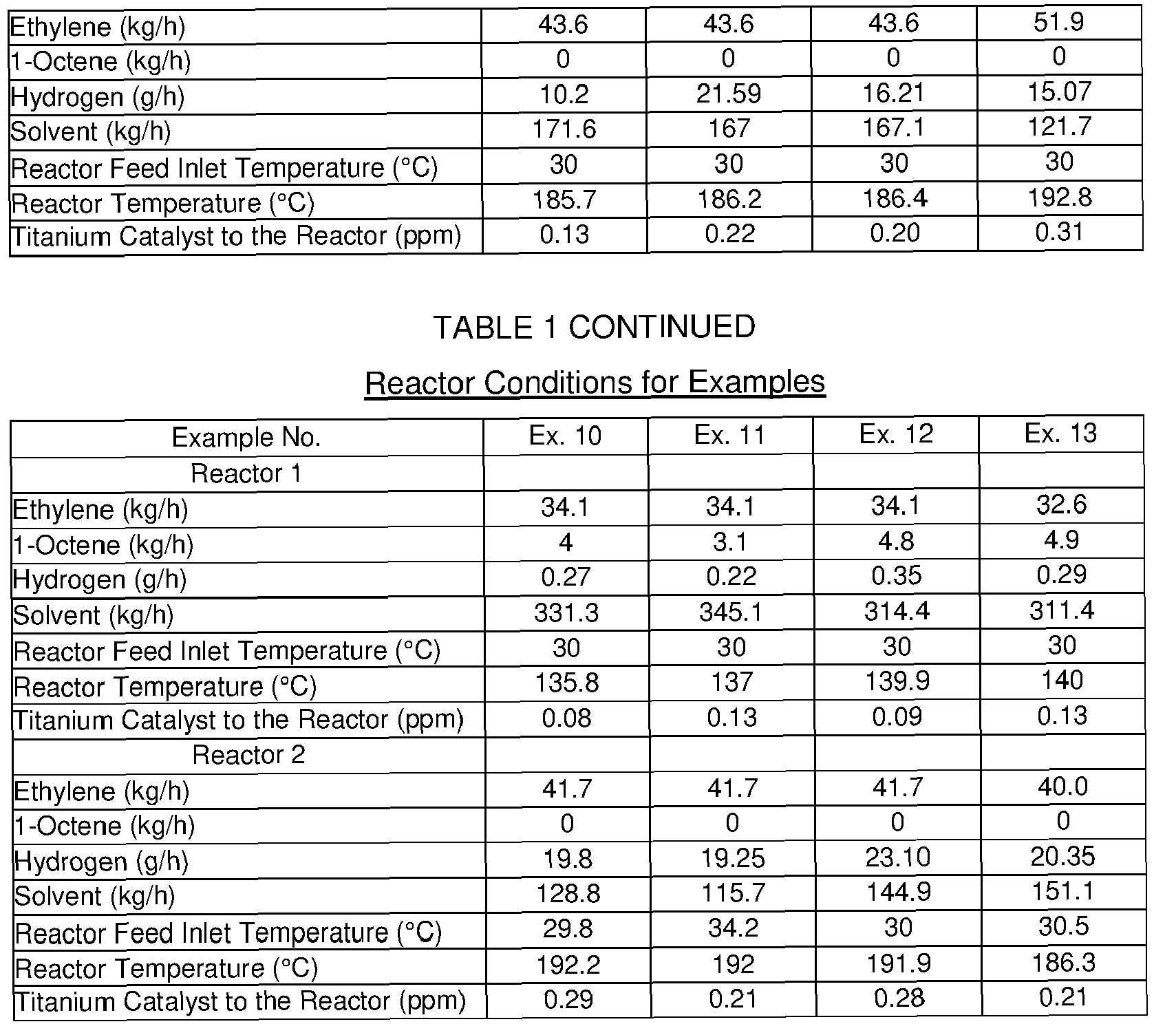


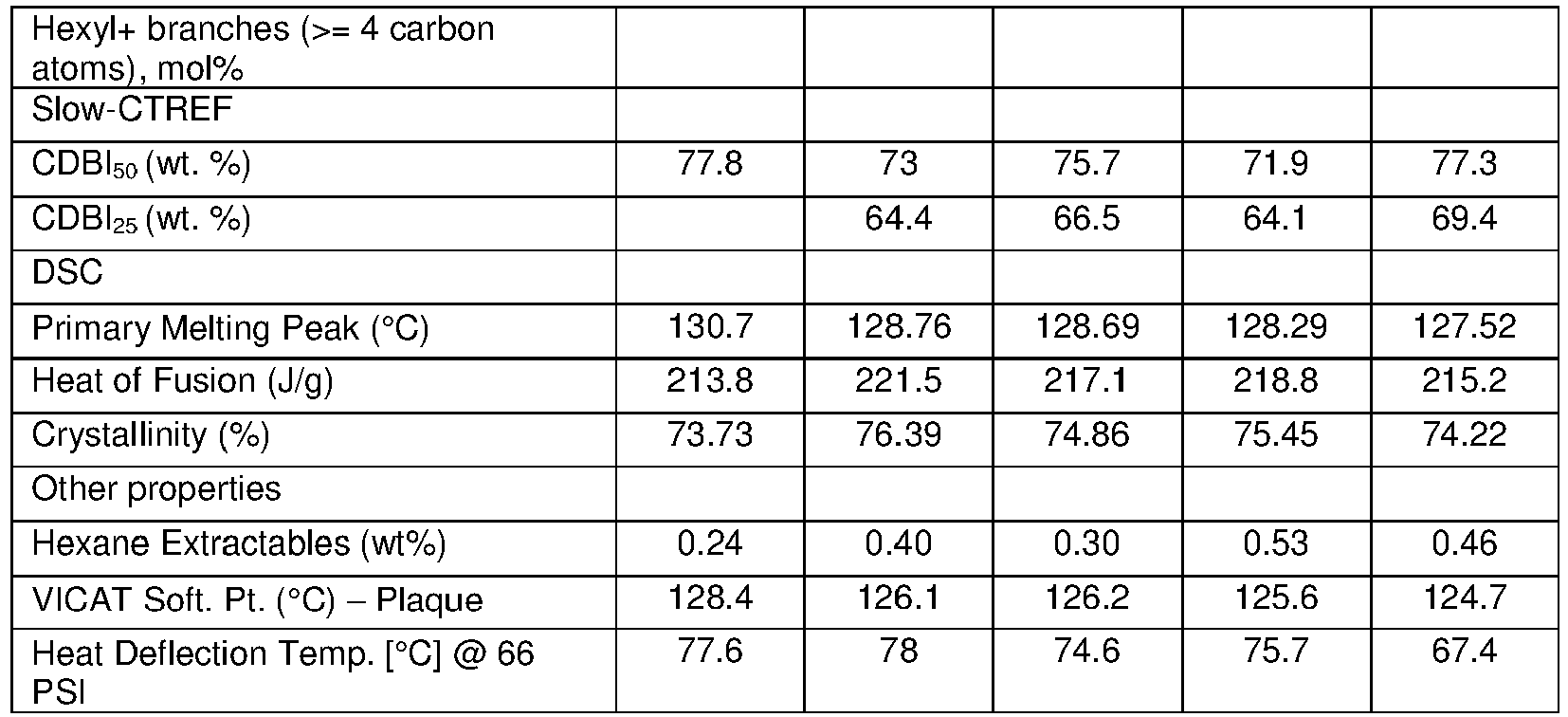


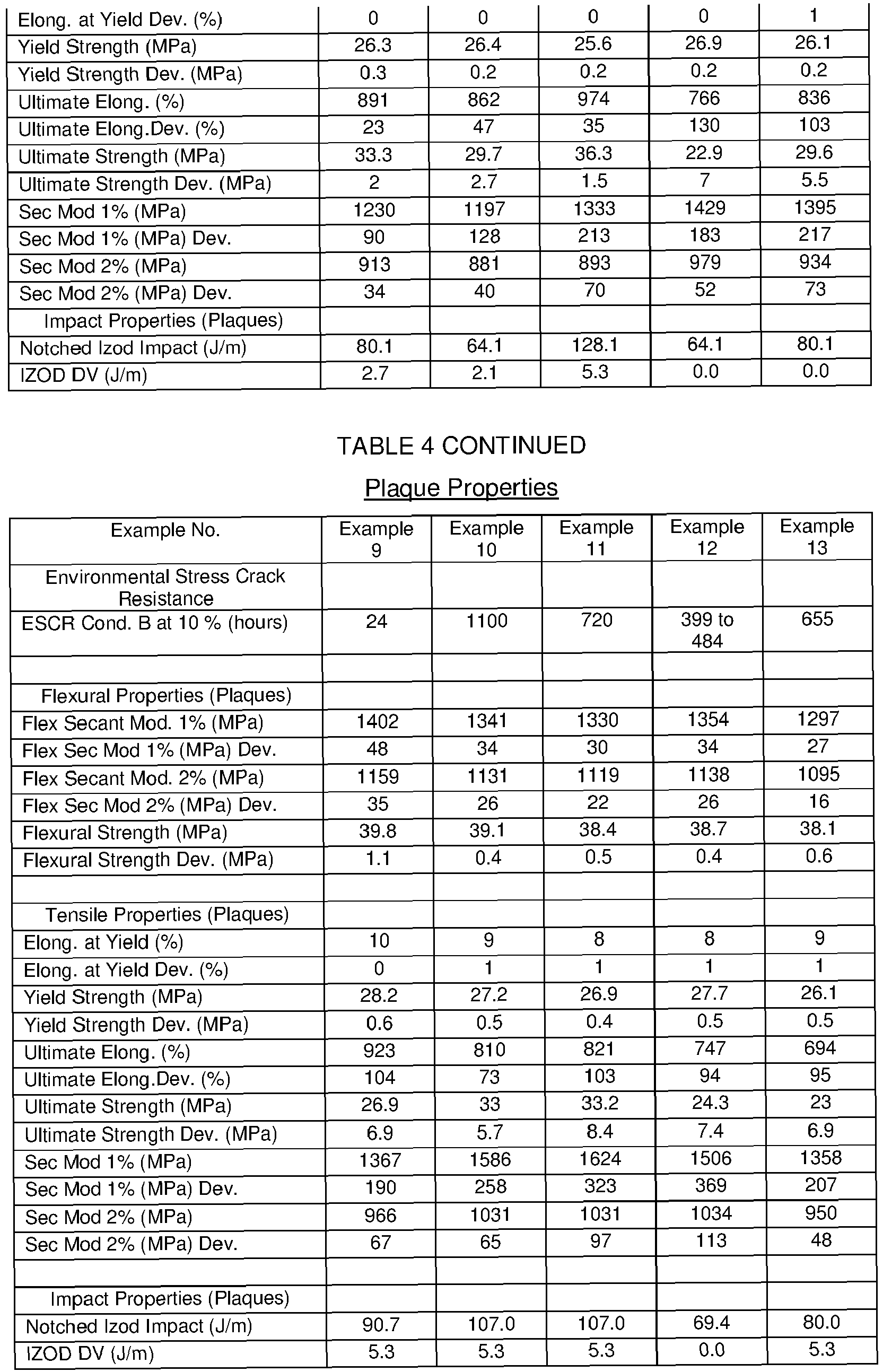
- As can be seen from the data provided in Tables 2, 3 and 4, the polyethylene compositions, Examples 1-13, which have a ratio of short chain branching SCB1/SCB2 of greater than 0.5, generally have improved ESCR B properties while maintaining good processability, relative to polyethylene compositions A-E. Polyethylene compositions A-E are embodiments not covered by the claimed invention.
- As shown in
Figure 8 ,polyethylene compositions - As shown in
Figure 9 ,polyethylene compositions - As shown in
Figure 10 ,polyethylene compositions -
Figure 11 shows thatpolyethylene compositions -
Figure 12 shows the bimodal nature of the polyethylene compositions 10-13. Each ethylene copolymer component has a Mw/Mn value of less than 2.5. -
Figures 13 and14 show that thepolyethylene compositions - The polyethylene compositions described above can be used in the formation of bottle closure assemblies. For example, bottle closure assemblies formed in part on in whole by compression molding and/or injection molding are contemplated.
- In one embodiment, the bottle closure assembly comprises the polyethylene composition described above and have a good balance of stiffness, processability and ESCR values. Hence the bottle closure assemblies are well suited for sealing bottles, containers and the like, for examples bottles that may contain drinkable water, and other foodstuffs, including but not limited to liquids that are pressurized.
- In an embodiment of the disclosure a bottle closure assembly comprising a polyethylene composition defined as above is prepared with a process comprising at least one compression molding step and/or at least one injection molding step.
- In order to provide a proxy of a tether portion which can be analyzed under conditions of shear, tear and tensile deformation, a closure (see
Figures 15A and 15B ) was compression molded as described below and then a tamper evident band, 10* (a proxy for a retaining means portion, 10) was formed by folding in and cutting the bottom circular edge of the closure using a folding/slitting machine with a modified blade, so that a tamper evident band (10*) which was joined to the cap portion (1) by several narrow ("pin" like) connecting sections (marked by the frangible line, 9 inFigures 15A and 15B ) and one larger continuous section (i.e. continuous with a portion of the cap portion side wall), with the larger continuous section serving as a proxy for a tether (the area marked as 40 inFigures 15A and 15B ). The larger continuous section or "tether proxy" section was designed to have an arcuate length of 6 mm. The "tether proxy" section had a cross-sectional width (or thickness) of 0.6 mm as determined by the dimensions of the closure mold used for the compression molding process (see below). The "tether proxy" section, or simply "tether proxy" 40 was then subjected to shear and tear deformations and to tensile deformation using a toque tester unit and tensile tester unit respectively (see below). - A SACMI Compression molding machine (model CCM24SB) and a PCO (plastic closure only) 1881 carbonated soft drink (CSD) closure mold was used to prepare the closures. Depending on material density, melt index (I2) and chosen plug size, the closure weight varied between 2.15 g and 2.45 grams, with the process conditions adjusted to target a closure having a weight of about 2.3 grams. During the closure preparation process, the overall closure dimensions, such as, for the example, the closure diameter and the closure height were measured and maintained within desired "quality-controlled" specifications. Closures with poor circularity or with significant deformation away from the pre-defined specifications were rejected by an automatic vision system installed on the compression molding machine. Once the closure had been compression molded, a tamper evident band, inclusive of one larger continuous section (a proxy for a tether portion) was cut into the closure bottom edge using a folding/slitting machine fitted with a modified blade. Both experimental and simulated data confirmed that 99% of any closure weight differences were due to differences in the top panel thickness (of the cap portion, see
Figure 15A ) for each of the compression molded closures. For example, in the closures prepared by compression molding, the top panel thickness values of closures having a weight ranging from 2.15 grams to 2.45 grams were found to be slightly different, but each of the closure side wall thicknesses were found to be identical. As a result, any small differences in the compression molded cap weight were expected to have no impact on the dimensions of the tamper evident band or the tether proxy section (see above): in each case, the tether proxy had an arcuate length of 6 mm and a cross-sectional thickness of 0.6 mm. -
Type 1 closures were compression molded from the polyethylene composition of Example 14, which was made in a manner substantially as described above for the polyethylene compositions of Examples 1-9. The Example 14 polyethylene composition properties and the properties of a pressed plaque made with the polyethylene composition are provided in Table 5.TABLE 5 Polymer and Polymer Plaque Properties Example No. 14 Density (g/cm3) 0.954 Rheology/Flow Properties Melt Index I2 (g/10 min) 1.12 Melt Flow Ratio (I21/I2) 56 Stress Exponent 1.33 Shear Viscosity (η) at 105 s-1 (240°C, Pa-s) 5.6 Shear viscosity Ratio (η100/η100000, 240°C) 183 GPC - conventional Mn 12513 MW 99834 Mz 295018 Polydispersity Index (Mw/Mn) 7.98 Mz/Mw 2.96 Branch Frequency - FTIR (uncorrected for chain end -CH3) Uncorrected SCB/1000C 2.3 Uncorrected comonomer content (mol%) 0.50 Internal unsaturation (/1000C) 0.02 Side chain unsaturation (/1000C) 0.01 Terminal unsaturation (/1000C) 0.09 Comonomer ID 1-octene Slow-CTREF CDBI50 (%) 73.1 CDBI25 (%) 63.8 DSC Primary Melting Peak (°C) 128.89 Heat of Fusion (J/g) 217.9 Crystallinity (%) 75.16 Environmental Stress Crack Resistance ESCR Cond. B at 10% (hrs) 182 Flexural Properties (Plaques) Flex Secant Mod. 2% (MPa) 1133 Impact Properties (Plaques) Izod Impact (ft-lb/in) 1.8 IZOD DV (ft-lb/inch) 0.1 Other properties Hexane Extractables (%) 0.45 VICAT Soft. Pt. (°C) - Plaque 127.3 Heat Deflection Temp. [°C] @ 66 PSI 71.3 -
Type 2 closures (Comparative) were compression molded from a unimodal polyethylene copolymer of ethylene and 1-butene having a melt index I2 of 32 g/10min, a density of 0.951 g/cm3, and a molecular weight distribution, Mw/Mn of 2.88, and which is made using a Ziegler-Natta catalyst in a solution olefin polymerization process. This resin is commercially available from NOVA Chemicals Corporation as SCLAIR® 2712. - The compression molding conditions used to make each closure type are provided in Table 6.
TABLE 6 Compression Molding Processing Conditions Closure Type No. 1 2 Closure Weight (g) 2.31 2.39 BT1 Temp (°C) 167 163 BT2 Temp (°C) 170 164 BT3 Temp (°C) 174 163 BT4 Temp (°C) 175 161 BT6 Temp (°C) 175 170 BT7 Temp (°C) 185 187 BT8 Temp (°C) 185 184 BT9 Temp (°C) 185 184 BT15 Temp (°C) 175 170 BT16 Temp (°C) 174 165 BT17 Temp (°C) 183 174 Metering Pump Set Press (bar) 50 50 Metering Pump Actual Press 1 (bar) IN 46 50 Metering Pump Actual Press 2 (bar) OUT 144 30.6 Pump Speed (%) 59.5 57 Hydraulic Operating Temp (°C) 45 46 Punch Cooling BT18 (°C) 20 20 Cavity Cooling BT19 (°C) 20 20 Ausiliari Cooling BT20 (°C) 30 30 - A TMS 5000 Torque Tester unit manufactured by Steinfurth was used to carry out the tether proxy shear deformation testing. The unit was adjusted to operate in "removal torque mode". A closure having a tether proxy section (
area 40 inFigures 15A and 15B ) with a 6 mm arcuate length and a 0.6 mm cross-sectional width connecting a cap portion (1) to a tamperevident band 10* (a proxy for a retaining means portion, 10) and suitable for mating with a PCO 1881 bottle finish was employed. Prior to testing, the tamper evident band (10*) was unfolded and then almost entirely removed, by cutting through the tamper evident band at a distance of approximately 2 mm from each end of the tether proxy section. The remaining portion of the tamper evident band (as shown inFigures 16A and 16B ) then, comprises the tether proxy section having an arcuate length of 6 mm, and a further 2 mm arcuate length section on either side of the tether proxy section, all of which has a cross sectional width of 0.6 mm. Adding 2 mm to either side of the tether proxy section provides a larger surface area to grip when carrying out the shear deformation testing. In order to support the closure for testing in the Torque Tester unit, a modified tubular preform was used (item 45 inFigure 16B ). Thetubular pre-form 45 was made of polyethylene terephthalate and was modified to have smooth outer walls. Following this, a brass rod (50), having a diameter which fit snuggly within the preform (45) was inserted as a plug to afford rigidity to the pre-form and to prevent its deformation during testing. Next, the closure was placed on top of the pre-form and the remaining section of the tamper evident band (10*) was clamped to the preform using vice grips. The closure and preform were then mounted within the Torque Tester. The cap portion (1) was gripped from above within a suitably designed chuck and rotated at a removal torque speed of 0.8 rpm, relative to the clamped section of the tamper evident band, using the Torque Tester. The shear strength of the tether proxy (40) is defined as the maximum torque (in inches.pounds) required to separate the cap portion (1) from the remaining section of the tamper evident band section (10*) by breaking the tether proxy (40). The reported shear strength in Table 7 is the average of at least 5 such shear deformation tests. - A TMS 5000 Torque Tester unit manufactured by Steinfurth was used to carry out the tether proxy shear deformation testing. The unit was adjusted to operate in "removal torque mode". A closure having a tether proxy section (
area 40 inFigures 15A and 15B ) with a 6 mm arcuate length and a 0.6 mm cross-sectional width connecting a cap portion (1) to a tamperevident band 10* (a proxy for a retaining means portion, 10) and suitable for mating with a PCO 1881 bottle finish was employed. In order to support the closure for testing in the Torque Tester unit, a modified tubular pre-form was used (item 45 inFigure 16C ). Thetubular pre-form 45 was made of polyethylene terephthalate and was modified to have smooth outer walls. Following this, a brass rod (50), having a diameter which fit snuggly within the pre-form (45) was inserted as a plug to afford rigidity to the pre-form and to prevent its deformation during testing. Next, the closure was placed on top of the preform. Prior to testing, the tamper evident band (10*) was deflected downward (on the opposite side of the tether proxy section) and away from the cap portion (1) as is shown inFigure 16C . The downward deflection breaks all the narrow pin sections (thefrangible line 9 inFigures 15A and 15B ) joining the top edge of the tamper evident band to the lower edge of the cap portion while leaving the larger continuous section, the tether proxy section (40), intact. The tamper evident band (10*) is deflected downward and away from the cap portion (1) until the top edge of the tamper evident band makes an angle with the lower edge of the cap portion of about 27 degrees, while the tether portion remains intact along its 6 mm arcuate length (seeFigure 16C ). The tamper evident band (10*) was then clamped to the pre-form in this downwardly deflected position using vice grips. The closure and pre-form were then mounted within the Torque Tester. The cap portion (1) was gripped from above within a suitably designed chuck and rotated at a removal torque speed of 0.8 rpm, relative to the clamped tamper evident band (10*), using the Torque Tester. The tear strength of the tether proxy (40) is defined as the maximum torque (in inches.pounds) required to separate the cap portion (1) from the downwardly deflected tamper evident band (10*) by breaking the tether proxy (40). The reported tear strength in Table 7 is the average of at least 5 such tear deformation tests. - Tensile deformation tests were performed using a tensile machine (an Instron 4204 universal tester, with a 1 KN (225 Ibf) capacity load cell) with the crosshead velocity set at 50 mm/min. A closure having a tether proxy section (
area 40 inFigures 15A and 15B ) with a 6 mm arcuate length and a 0.6 mm cross-sectional width connecting a cap portion (1) to a tamperevident band 10* (a proxy for a retaining means portion, 10) and suitable for mating with a PCO 1881 bottle finish was employed. Prior to testing, the tamper evident band (10*) was unfolded and then almost entirely removed, by cutting through the tamper evident band at a distance of approximately 2 mm from each end of the tether proxy section (seeFigures 16A ,17A and 17B ). The remaining portion of the tamper evident band (as shown inFigures 16A ,17A and 17B ) then, comprises the tether proxy section having an arcuate length of 6 mm, and a further 2 mm arcuate length section on either side of the tether proxy section, all of which has a cross sectional width of 0.6 mm. Adding 2 mm to either side of the tether proxy section provides a larger surface area to grip when carrying out the tensile deformation testing. For the tensile deformation test, most of the cap portion (1) was similarly cut away, leaving only a section of the cap portion side wall connected to the what was left of the tamper evident band (seeFigures 17A and 17B ). This "cut away" section of the closure was then mounted in the tensile tester, with the remaining cap portion side wall and the remaining tamper evident band each being secured with 0.5-inch wide steel serrated grips at a 0.25-inch grip separation. During the tensile testing, the remaining section of the cap portion (1) and the remaining section of the tamper evident band (10*) were drawn apart vertically. The tensile strength of the tether proxy (40) is defined as the maximum load (in grams.force, gf) required to separate the remaining cap portion (1) from the remaining tamper evident band section (10*) by breaking the tether proxy (40). The reported tensile strength in Table 7 is the average of at least 5 such tensile deformation tests.TABLE 7 Average Shear, Tear and Tensile Deformation of a Tether Proxy Closure Type No. 1 2 (Comparative) Shear Strength (inches.pounds) 11.14 9.43 Tear Strength (inches.pounds) 10.58 9.18 Tensile Strength (grams.force) 13910 12800 - A person skilled in the art will recognize from the data provided in Table 7, that a tether proxy made using a polyethylene composition according to the current disclosure (e.g. the polyethylene composition of Example 14) may have a relatively good ability to resist shear and tear deformations, while tensile deformation is not statistically different (beyond a 95% confidence level), relative to a comparative tether proxy made from a unimodal polyethylene copolymer of ethylene and 1-butene (SCLAIR 2712). The data thus provides further evidence that the polyethylene compositions described herein may be useful in the production of bottle closure assemblies, by preventing facile separation of a cap portion from a retaining means portion or from a bottle, and by generally helping to prevent loss or disassociation of a cap portion (a potential plastic waste stream) from a bottle, where the cap portion could otherwise contribute to environmental waste concerns.
- The present disclosure has been described with reference to certain details of particular embodiments thereof. It is not intended that such details be regarded as limitations upon the scope of the disclosure except insofar as and to the extent that they are included in the accompanying claims.
- The disclosure provides a bottle closure assembly which is made at least in part with a polyethylene composition comprising i) a first ethylene copolymer and ii) a second ethylene copolymer or an ethylene homopolymer. The bottle closure assembly comprises a cap or closure portion, a tether portion and a retaining means portion, where the tether portion helps to prevent loss or disassociation of a cap or closure portion from a bottle or container, which may otherwise contribute to environmental waste streams.
Claims (12)
- A bottle closure assembly comprising:an integrally molded: cap portion, elongated tether portion, and retaining means portion; the cap portion being molded to reversibly engage and cover a bottle opening, the retaining means portion being molded to irreversibly engage a bottle neck or an upper portion of a bottle, and the elongated tether portion being molded to connect at least one point on the cap portion to at least one point on the retaining means portion; wherein the integrally molded: cap portion,elongated tether portion and retaining means portion are made from a polyethylene composition comprising:(1) 10 to 70 wt% of a first ethylene copolymer having a melt index I2, of less than 1.0 g/10min; and a density of from 0.920 to 0.960 g/cm3, as measured according to ASTM D792; and(2) 90 to 30 wt% of a second ethylene copolymer or an ethylene homopolymer; the second ethylene copolymer or the ethylene homopolymer having a melt index I2, of at least 20 g/10min, as measured according to ASTM D1238 (when conducted at 190°C, using a 2.16 kg weight); and a density higher than the density of the first ethylene copolymer, but less than 0.970 g/cm3;
wherein the ratio (SCB1/SCB2) of the number of short chain branches per thousand carbon atoms in said first ethylene copolymer (SCB1) to the number of short chain branches per thousand carbon atoms in said second ethylene copolymer (SCB2) is greater than 0.5;
and wherein the polyethylene composition has a tensile elongation at break of at least 600 percent, a tensile strength at break of at least 20 MPa, and a melt index, I2, of from 0.1 to 4.0 g/10min. - A bottle closure assembly according to claim 1, wherein the retaining means portion is a retaining collar portion.
- A bottle closure assembly according to claim 2, wherein the elongated tether portion comprises a tether strip which is frangibly connected along a portion of its upper edge to a descending annular edge of the cap portion and which is frangibly connected along a portion of its lower edge to an upper annular edge of the retaining collar portion, the tether strip being integrally formed with and connected at one end to at least one point on the cap portion and integrally formed with and connected at another end to at least one point on the retaining collar portion, the frangible sections being breakable when the cap portion is removed from a bottle opening, but where the cap portion remains connected to the retaining collar portion via the tether strip.
- The bottle closure assembly of claim 1, 2, or 3, wherein the ratio (SCB1/SCB2) of the number of short chain branches per thousand carbon atoms in said first ethylene copolymer (SCB1) to the number of short chain branches per thousand carbon atoms in said second ethylene copolymer (SCB2) is at least 1.0.
- The bottle closure assembly of any one of claims 1 to 4, wherein the polyethylene composition has a Z-average molecular weight Mz, of less than 450,000.
- The bottle closure assembly of any one of claims 1 to 5, wherein the density of the second ethylene copolymer is higher than the density of the first ethylene copolymer, but less than 0.037 g/cm3 higher than the density of the first ethylene copolymer, as measured according to ASTM D792.
- The bottle closure assembly of any one of claims 1 to 6, wherein the polyethylene composition has an ESCR Condition B at 10% of at least 20 hours, as measured according to ASTM D1693 at 50 °C using 10% Igepal.
- The bottle closure assembly of claim 7, wherein the polyethylene composition has an ESCR Condition B at 10% of at least 300 hours, as measured according to ASTM D1693 at 50 °C using 10% Igepal.
- The bottle closure assembly of claim 1, 2 or 3, wherein the polyethylene composition has a shear viscosity ratio, SVR(10,1000) at 240°C, of from 4.0 to 25; wherein the shear viscosity ratio is the ratio of the shear viscosity at a shear rate of 10 s-1 to the shear viscosity at a shear rate of 1000 s-1, measured with a capillary rheometer at a constant temperature of 240 °C with a die having an L/D ratio of 20 and a diameter of 0.1524 cm.
- The bottle closure assembly of claim 1, 2 or 3, wherein the polyethylene composition has a density of at least 0.949 g/cm3, as measured according to ASTM D792.
- The bottle closure assembly of claim 1, 2 or 3, wherein the second polyethylene copolymer has a melt index I2, of from 1,500 to 15,000 g/10min, as measured according to ASTM D1238 (when conducted at 190°C, using a 2.16 kg weight).
- The bottle closure assembly of claim 1, 2 or 3, wherein the polyethylene composition has a stress exponent, Log10[I6/I2]/Log10[6.48/2.16] of equal to or less than 1.53.
Applications Claiming Priority (2)
| Application Number | Priority Date | Filing Date | Title |
|---|---|---|---|
| US201762594068P | 2017-12-04 | 2017-12-04 | |
| PCT/IB2018/059483 WO2019111111A1 (en) | 2017-12-04 | 2018-11-30 | Bottle closure assembly comprising a polyethylene composition |
Publications (2)
| Publication Number | Publication Date |
|---|---|
| EP3720906A1 EP3720906A1 (en) | 2020-10-14 |
| EP3720906B1 true EP3720906B1 (en) | 2023-03-08 |
Family
ID=64901612
Family Applications (1)
| Application Number | Title | Priority Date | Filing Date |
|---|---|---|---|
| EP18827239.7A Active EP3720906B1 (en) | 2017-12-04 | 2018-11-30 | Bottle closure assembly comprising a polyethylene composition |
Country Status (17)
| Country | Link |
|---|---|
| US (1) | US10625914B2 (en) |
| EP (1) | EP3720906B1 (en) |
| JP (1) | JP2021505491A (en) |
| KR (1) | KR20200091417A (en) |
| CN (1) | CN111406093B (en) |
| AR (1) | AR113605A1 (en) |
| AU (1) | AU2018378157A1 (en) |
| BR (1) | BR112020009680B1 (en) |
| CA (1) | CA3022996A1 (en) |
| CL (1) | CL2020001368A1 (en) |
| DK (1) | DK3720906T3 (en) |
| ES (1) | ES2945466T3 (en) |
| FI (1) | FI3720906T3 (en) |
| MX (1) | MX2020005180A (en) |
| PE (1) | PE20201141A1 (en) |
| SG (1) | SG11202005124RA (en) |
| WO (1) | WO2019111111A1 (en) |
Families Citing this family (11)
| Publication number | Priority date | Publication date | Assignee | Title |
|---|---|---|---|---|
| US11312544B2 (en) * | 2020-03-30 | 2022-04-26 | ThisCap, Inc. | Cap for container |
| CA3022996A1 (en) | 2017-12-04 | 2019-06-04 | Nova Chemicals Corporation | Bottle closure assembly comprising a polyethylene composition |
| CA3028157A1 (en) * | 2018-12-20 | 2020-06-20 | Nova Chemicals Corporation | Polyethylene copolymer compositions and their barrier properties |
| CA3028148A1 (en) * | 2018-12-20 | 2020-06-20 | Nova Chemicals Corporation | Polyethylene copolymer compositions and articles with barrier properties |
| CA3032082A1 (en) * | 2019-01-31 | 2020-07-31 | Nova Chemicals Corporation | Polyethylene compositions and articles with good barrier properties |
| MX2022003784A (en) | 2019-09-30 | 2022-04-25 | Berry Global Inc | Retainable closure. |
| EP4045589A1 (en) * | 2019-10-16 | 2022-08-24 | Nova Chemicals (International) S.A. | Use of recycled polyethylene in closures for bottles |
| CA3158392A1 (en) * | 2019-11-01 | 2021-05-06 | Nova Chemicals Corporation | Linear high-density polyethylene with high toughness and high escr |
| KR102621528B1 (en) * | 2020-11-18 | 2024-01-04 | 롯데케미칼 주식회사 | Polyethylene resin composition with reduced deformation due to temperature change |
| US20230391501A1 (en) * | 2021-09-02 | 2023-12-07 | Merrilee Kick | Container apparatus |
| CN114560176A (en) * | 2022-03-17 | 2022-05-31 | 张大朋 | Bottle cap, container and opening method of container |
Citations (18)
| Publication number | Priority date | Publication date | Assignee | Title |
|---|---|---|---|---|
| DE2430775A1 (en) | 1973-07-02 | 1975-01-23 | Somepla Sa | Captive bottle cap with damage-proof thread |
| US4573602A (en) | 1984-07-10 | 1986-03-04 | Goldberg James R | Molded safety closure device and method for making same |
| EP1462378A2 (en) | 2001-11-09 | 2004-09-29 | SOLVAY POLYOLEFINS EUROPE - BELGIUM (Société Anonyme) | Screw cap composition based on multimodal polyethylene |
| EP1655336A1 (en) | 2004-11-03 | 2006-05-10 | Borealis Technology Oy | Multimodal polyethylene composition for injection moulded caps and closure articles |
| US20090236304A1 (en) | 2005-04-15 | 2009-09-24 | Richard Wayne Watson | Environmentally Friendly Tamper-Evident Safety Closure |
| WO2009129597A1 (en) | 2008-04-21 | 2009-10-29 | Nova Chemicals (International) S.A. | Closures for bottles from bimodal polyethylene compositions |
| US20130343808A1 (en) | 2012-06-11 | 2013-12-26 | Brett Christopher Domoy | High Density Polyethylene Composition and Closure |
| US8720716B2 (en) | 2009-06-25 | 2014-05-13 | Phillip John Campbell | Closure with spring loaded tether docking |
| US20150025827A1 (en) | 2010-08-04 | 2015-01-22 | Stmicroelectronics (Rousset) Sas | Method of detecting an object with a proximity sensor |
| WO2015061834A1 (en) | 2013-10-31 | 2015-05-07 | Doran Brian | Capping device for a container |
| US20150251827A1 (en) | 2014-03-10 | 2015-09-10 | Phillip John Campbell | Closure with spring loaded tether docking |
| US20150259519A1 (en) | 2012-12-14 | 2015-09-17 | Nova Chemicals (International) S.A. | Polyethylene compositions having high dimensional stability and excellent processability for caps and closures |
| US20150353715A1 (en) | 2011-09-19 | 2015-12-10 | Nova Chemicals (International) S.A. | Polyethylene compositions and closures made from them |
| US20160289435A1 (en) | 2012-12-14 | 2016-10-06 | Nova Chemicals (International) S.A. | Polyethylene compositions having high dimensional stability and excellent processability for caps and closures |
| WO2017029571A1 (en) | 2015-08-19 | 2017-02-23 | Nova Chemicals (International) S.A. | Polyethylene compositions, process and closures |
| US20180029269A1 (en) | 2015-03-12 | 2018-02-01 | Husky Injection Molding Systems Ltd. | Injection mold having an in-mold lid closing device |
| WO2019106477A1 (en) | 2017-11-29 | 2019-06-06 | Nova Chemicals (International) S.A. | Bottle closure assembly comprising a polyethylene composition having good dimensional stability |
| WO2019111111A1 (en) | 2017-12-04 | 2019-06-13 | Nova Chemicals (International) S.A. | Bottle closure assembly comprising a polyethylene composition |
Family Cites Families (57)
| Publication number | Priority date | Publication date | Assignee | Title |
|---|---|---|---|---|
| US3022143A (en) | 1959-03-10 | 1962-02-20 | E I Du Pont De Nemoursand Comp | Process for drying hydrogen cyanide |
| CA849081A (en) | 1967-03-02 | 1970-08-11 | Du Pont Of Canada Limited | PRODUCTION OF ETHYLENE/.alpha.-OLEFIN COPOLYMERS OF IMPROVED PHYSICAL PROPERTIES |
| US5324800A (en) | 1983-06-06 | 1994-06-28 | Exxon Chemical Patents Inc. | Process and catalyst for polyolefin density and molecular weight control |
| US4474302A (en) | 1983-11-03 | 1984-10-02 | James R. Goldberg | Safety champagne cork |
| US4557393A (en) | 1984-04-17 | 1985-12-10 | Continental White Cap, Inc. | Snap-on cap with tethering strap |
| US4805792A (en) | 1984-04-17 | 1989-02-21 | Continental White Cap, Inc. | Litterless tamper indicating closure |
| US4583652A (en) | 1984-07-10 | 1986-04-22 | Goldberg James R | Safety closure device |
| US4564114A (en) | 1984-12-21 | 1986-01-14 | James R. Goldberg | Molded safety closure device |
| US4808561A (en) | 1985-06-21 | 1989-02-28 | Exxon Chemical Patents Inc. | Supported polymerization catalyst |
| US4701432A (en) | 1985-11-15 | 1987-10-20 | Exxon Chemical Patents Inc. | Supported polymerization catalyst |
| US4798081A (en) | 1985-11-27 | 1989-01-17 | The Dow Chemical Company | High temperature continuous viscometry coupled with analytic temperature rising elution fractionation for evaluating crystalline and semi-crystalline polymers |
| US5055438A (en) | 1989-09-13 | 1991-10-08 | Exxon Chemical Patents, Inc. | Olefin polymerization catalysts |
| US4937301A (en) | 1987-12-17 | 1990-06-26 | Exxon Chemical Patents Inc. | Method for preparing a supported metallocene-alumoxane catalyst for gas phase polymerization |
| US4935397A (en) | 1988-09-28 | 1990-06-19 | Exxon Chemical Patents Inc. | Supported metallocene-alumoxane catalyst for high pressure polymerization of olefins and a method of preparing and using the same |
| NZ235032A (en) | 1989-08-31 | 1993-04-28 | Dow Chemical Co | Constrained geometry complexes of titanium, zirconium or hafnium comprising a substituted cyclopentadiene ligand; use as olefin polymerisation catalyst component |
| US5057475A (en) | 1989-09-13 | 1991-10-15 | Exxon Chemical Patents Inc. | Mono-Cp heteroatom containing group IVB transition metal complexes with MAO: supported catalyst for olefin polymerization |
| US5064802A (en) | 1989-09-14 | 1991-11-12 | The Dow Chemical Company | Metal complex compounds |
| PL166690B1 (en) | 1990-06-04 | 1995-06-30 | Exxon Chemical Patents Inc | Method of obtaining polymers of olefins |
| CA2113627A1 (en) | 1991-07-18 | 1993-02-18 | Prasadarao Meka | Heat sealed article |
| JP3046428B2 (en) | 1991-12-05 | 2000-05-29 | 旭電化工業株式会社 | Crystalline synthetic resin composition |
| US5206075A (en) | 1991-12-19 | 1993-04-27 | Exxon Chemical Patents Inc. | Sealable polyolefin films containing very low density ethylene copolymers |
| EP0552946B1 (en) | 1992-01-23 | 1997-04-16 | Mitsui Petrochemical Industries, Ltd. | Ethylene/alpha-olefin/7-methyl-1,6-octadiene copolymer rubber and composition of the same |
| KR100262833B1 (en) | 1992-09-16 | 2000-08-01 | 벤 씨. 카덴헤드 | Soft films having enhanced physical properties |
| US5725115A (en) | 1995-02-21 | 1998-03-10 | Crown Cork Ag | Closure cap with tether |
| US6066588A (en) | 1995-11-22 | 2000-05-23 | Fina Research, S.A. | Bridged metallocenes catalyst for polymerization of olefins |
| US6759499B1 (en) | 1996-07-16 | 2004-07-06 | Exxonmobil Chemical Patents Inc. | Olefin polymerization process with alkyl-substituted metallocenes |
| CZ20999A3 (en) | 1996-07-22 | 1999-04-14 | The Dow Chemical Company | Metal complexes containing bridge non-aromatic anionic dienyl groups, addition polymerization catalysts based on such complexes and polymerization process |
| US5981636A (en) | 1996-12-27 | 1999-11-09 | 3M Innovative Properties Company | Modifying agents for polyolefins |
| CA2206944C (en) | 1997-05-30 | 2006-08-29 | Douglas W. Stephan | High temperature solution polymerization process |
| CA2215444C (en) | 1997-09-15 | 2005-08-02 | Stephen John Brown | Catalyst having a ketimide ligand |
| CA2245375C (en) | 1998-08-19 | 2006-08-15 | Nova Chemicals Ltd. | Dual reactor polyethylene process using a phosphinimine catalyst |
| CA2247703C (en) | 1998-09-22 | 2007-04-17 | Nova Chemicals Ltd. | Dual reactor ethylene polymerization process |
| CA2278042C (en) | 1999-07-19 | 2008-12-16 | Nova Chemicals Corporation | Mixed phosphinimine catalyst |
| SI20739A (en) | 2000-11-28 | 2002-06-30 | G.Loc, Trgovina In Storitve D.O.O. | A cap of a container, especially bottle or plastic bottle |
| ATE376005T1 (en) | 2000-12-04 | 2007-11-15 | Univaton Technologies Llc | POLYMERIZATION PROCESS |
| US6465551B1 (en) | 2001-03-24 | 2002-10-15 | Milliken & Company | Bicyclo[2.2.1]heptane dicarboxylate salts as polyolefin nucleators |
| US6599971B2 (en) | 2001-03-29 | 2003-07-29 | Milliken & Company | Metals salts of hexahydrophthalic acid as nucleating additives for crystalline thermoplastics |
| CA2347410C (en) | 2001-05-11 | 2009-09-08 | Nova Chemicals Corporation | Solution polymerization process catalyzed by a phosphinimine catalyst |
| CA2411183C (en) | 2002-11-05 | 2011-06-14 | Nova Chemicals Corporation | Heterogeneous/homogeneous copolymer |
| JP2005041566A (en) * | 2003-07-22 | 2005-02-17 | Akira Igawa | Keeping cap |
| JP3870226B2 (en) * | 2003-09-04 | 2007-01-17 | 昭司 神谷 | Bottle cap closure structure |
| US7790826B2 (en) | 2004-05-06 | 2010-09-07 | DowGlobal Technologies Inc. | Polymer molding compositions |
| ATE351886T1 (en) | 2004-11-03 | 2007-02-15 | Borealis Tech Oy | MULTIMODAL POLYETHYLENE COMPOSITION FOR TRANSPORT PACKAGING ARTICLES PRODUCED BY INJECTION MOLDING |
| US20060247373A1 (en) | 2005-04-28 | 2006-11-02 | Nova Chemicals (International) S.A. | Dual reactor polyethylene resins for electronic packaging-films, tapes, bags and pouches |
| USD593856S1 (en) | 2007-01-30 | 2009-06-09 | Kenneth Kubler | Bottle cap retainer |
| US20080197135A1 (en) | 2007-02-20 | 2008-08-21 | Berman Ronald H | Beverage spout with safety tether |
| US8443994B1 (en) | 2009-09-09 | 2013-05-21 | Michael C. Desselle | Tethered bottle cap assembly with means to retain a detached cap portion |
| US8198351B2 (en) | 2009-10-21 | 2012-06-12 | Milliken & Company | Thermoplastic polymer composition |
| CA2688217C (en) | 2009-12-11 | 2016-07-12 | Nova Chemicals Corporation | Multi reactor process |
| CA2752407C (en) * | 2011-09-19 | 2018-12-04 | Nova Chemicals Corporation | Polyethylene compositions and closures for bottles |
| CA2798854C (en) | 2012-12-14 | 2020-02-18 | Nova Chemicals Corporation | Polyethylene compositions having high dimensional stability and excellent processability for caps and closures |
| US9493283B2 (en) | 2013-08-02 | 2016-11-15 | Bradley P. Tuyn | Bottle cap attachment mechanism |
| US9193845B2 (en) | 2013-09-23 | 2015-11-24 | Milliken & Company | Thermoplastic polymer composition |
| US9200142B2 (en) | 2013-09-23 | 2015-12-01 | Milliken & Company | Thermoplastic polymer composition |
| US9200144B2 (en) | 2013-09-23 | 2015-12-01 | Milliken & Company | Thermoplastic polymer composition |
| CA2868640C (en) | 2014-10-21 | 2021-10-26 | Nova Chemicals Corporation | Solution polymerization process |
| US9783664B1 (en) | 2016-06-01 | 2017-10-10 | Nova Chemicals (International) S.A. | Hinged component comprising polyethylene composition |
-
2018
- 2018-11-05 CA CA3022996A patent/CA3022996A1/en active Pending
- 2018-11-30 PE PE2020000679A patent/PE20201141A1/en unknown
- 2018-11-30 EP EP18827239.7A patent/EP3720906B1/en active Active
- 2018-11-30 ES ES18827239T patent/ES2945466T3/en active Active
- 2018-11-30 AU AU2018378157A patent/AU2018378157A1/en not_active Abandoned
- 2018-11-30 DK DK18827239.7T patent/DK3720906T3/en active
- 2018-11-30 BR BR112020009680-6A patent/BR112020009680B1/en active IP Right Grant
- 2018-11-30 MX MX2020005180A patent/MX2020005180A/en unknown
- 2018-11-30 JP JP2020547461A patent/JP2021505491A/en active Pending
- 2018-11-30 CN CN201880078259.4A patent/CN111406093B/en active Active
- 2018-11-30 SG SG11202005124RA patent/SG11202005124RA/en unknown
- 2018-11-30 FI FIEP18827239.7T patent/FI3720906T3/en active
- 2018-11-30 WO PCT/IB2018/059483 patent/WO2019111111A1/en unknown
- 2018-11-30 KR KR1020207016030A patent/KR20200091417A/en not_active Application Discontinuation
- 2018-12-04 US US16/208,951 patent/US10625914B2/en active Active
- 2018-12-04 AR ARP180103544A patent/AR113605A1/en unknown
-
2020
- 2020-05-25 CL CL2020001368A patent/CL2020001368A1/en unknown
Patent Citations (20)
| Publication number | Priority date | Publication date | Assignee | Title |
|---|---|---|---|---|
| US3904062A (en) | 1973-07-02 | 1975-09-09 | Somepla Sa | Tamper-proof and loss-proof screw-type bottle cap |
| DE2430775A1 (en) | 1973-07-02 | 1975-01-23 | Somepla Sa | Captive bottle cap with damage-proof thread |
| US4573602A (en) | 1984-07-10 | 1986-03-04 | Goldberg James R | Molded safety closure device and method for making same |
| EP1462378A2 (en) | 2001-11-09 | 2004-09-29 | SOLVAY POLYOLEFINS EUROPE - BELGIUM (Société Anonyme) | Screw cap composition based on multimodal polyethylene |
| EP1655336A1 (en) | 2004-11-03 | 2006-05-10 | Borealis Technology Oy | Multimodal polyethylene composition for injection moulded caps and closure articles |
| US20090236304A1 (en) | 2005-04-15 | 2009-09-24 | Richard Wayne Watson | Environmentally Friendly Tamper-Evident Safety Closure |
| WO2009129597A1 (en) | 2008-04-21 | 2009-10-29 | Nova Chemicals (International) S.A. | Closures for bottles from bimodal polyethylene compositions |
| US8720716B2 (en) | 2009-06-25 | 2014-05-13 | Phillip John Campbell | Closure with spring loaded tether docking |
| US20150025827A1 (en) | 2010-08-04 | 2015-01-22 | Stmicroelectronics (Rousset) Sas | Method of detecting an object with a proximity sensor |
| US20150353715A1 (en) | 2011-09-19 | 2015-12-10 | Nova Chemicals (International) S.A. | Polyethylene compositions and closures made from them |
| US9371442B2 (en) | 2011-09-19 | 2016-06-21 | Nova Chemicals (International) S.A. | Polyethylene compositions and closures made from them |
| US20130343808A1 (en) | 2012-06-11 | 2013-12-26 | Brett Christopher Domoy | High Density Polyethylene Composition and Closure |
| US20160289435A1 (en) | 2012-12-14 | 2016-10-06 | Nova Chemicals (International) S.A. | Polyethylene compositions having high dimensional stability and excellent processability for caps and closures |
| US20150259519A1 (en) | 2012-12-14 | 2015-09-17 | Nova Chemicals (International) S.A. | Polyethylene compositions having high dimensional stability and excellent processability for caps and closures |
| WO2015061834A1 (en) | 2013-10-31 | 2015-05-07 | Doran Brian | Capping device for a container |
| US20150251827A1 (en) | 2014-03-10 | 2015-09-10 | Phillip John Campbell | Closure with spring loaded tether docking |
| US20180029269A1 (en) | 2015-03-12 | 2018-02-01 | Husky Injection Molding Systems Ltd. | Injection mold having an in-mold lid closing device |
| WO2017029571A1 (en) | 2015-08-19 | 2017-02-23 | Nova Chemicals (International) S.A. | Polyethylene compositions, process and closures |
| WO2019106477A1 (en) | 2017-11-29 | 2019-06-06 | Nova Chemicals (International) S.A. | Bottle closure assembly comprising a polyethylene composition having good dimensional stability |
| WO2019111111A1 (en) | 2017-12-04 | 2019-06-13 | Nova Chemicals (International) S.A. | Bottle closure assembly comprising a polyethylene composition |
Non-Patent Citations (8)
| Title |
|---|
| ANONYMOUS: "Environmental Stress Crack Resistance Of Polyethylene", INEOS OLEFINS & POLYMERS USA - TECHNICAL INFORMATION, 1 May 2008 (2008-05-01), XP093146535, Retrieved from the Internet <URL:https://www.ineos.com> [retrieved on 20240328] |
| ANONYMOUS: "Purell ACP 6541A - Product Description", LYONDELLBASELL, 15 June 2012 (2012-06-15), XP093148456, Retrieved from the Internet <URL:https://plastore.it/cgi2018/file818/1961_pe%20hd%20purell%20acp6541a.pdf> [retrieved on 20240405] |
| ANONYMOUS: "Purell ACP 6541A", LYONDELLBASELL, 14 December 2015 (2015-12-14), XP093148458, [retrieved on 20240405] |
| ASTM INTERNATIONAL: "Standard Test Method for Tensile Properties of Plastics", ASTM DESIGNATION D638-08, 1 January 2008 (2008-01-01), pages 1 - 16, XP055479906 |
| ASTM: "Standard Test Method for Flow Rates of Thermoplastics by Extrusion Plastometer", ASTM DESIGNATION: D1238-98, ASTM INTERNATIONAL, 1 January 1999 (1999-01-01), pages 1 - 10, XP093146532, Retrieved from the Internet <URL:https://www.astm.org> [retrieved on 20240328] |
| ASTM: "Standard Test Method for Tensile Properties of Plastics", ASTM DESIGNATION: D638-10, ASTM INTERNATIONAL, WEST CONSHOHOCKEN, PA, 15 May 2010 (2010-05-15), West Conshohocken, PA, pages 1 - 16, XP093146531, Retrieved from the Internet <URL:https://www.astm.org/d0638-14.html> [retrieved on 20240328], DOI: 10.1520/D0638-10 |
| CAHOON SCOTT: "Living Hinge: Design Guidelines and Material Selection", MATTERHACKERS, 7 September 2016 (2016-09-07), XP093148336, Retrieved from the Internet <URL:https://www.matterhackers.com/news/living-hinge:--design-guidelines-and-material-selection> [retrieved on 20240405] |
| KRISHNASWAMY RAJENDRA K., YANG QING, FERNANDEZ-BALLESTER LUCIA, KORNFIELD JULIA A.: "Effect of the Distribution of Short-Chain Branches on Crystallization Kinetics and Mechanical Properties of High-Density Polyethylene", MACROMOLECULES, AMERICAN CHEMICAL SOCIETY, US, vol. 41, no. 5, 1 March 2008 (2008-03-01), US , pages 1693 - 1704, XP093028686, ISSN: 0024-9297, DOI: 10.1021/ma070454h |
Also Published As
| Publication number | Publication date |
|---|---|
| DK3720906T3 (en) | 2023-05-22 |
| BR112020009680A2 (en) | 2020-11-10 |
| ES2945466T3 (en) | 2023-07-03 |
| US20190168936A1 (en) | 2019-06-06 |
| KR20200091417A (en) | 2020-07-30 |
| CA3022996A1 (en) | 2019-06-04 |
| SG11202005124RA (en) | 2020-06-29 |
| AU2018378157A1 (en) | 2020-04-16 |
| PE20201141A1 (en) | 2020-10-26 |
| AR113605A1 (en) | 2020-05-20 |
| CL2020001368A1 (en) | 2020-12-18 |
| US10625914B2 (en) | 2020-04-21 |
| MX2020005180A (en) | 2020-08-20 |
| JP2021505491A (en) | 2021-02-18 |
| WO2019111111A1 (en) | 2019-06-13 |
| EP3720906A1 (en) | 2020-10-14 |
| CN111406093B (en) | 2023-10-03 |
| FI3720906T3 (en) | 2023-05-25 |
| BR112020009680B1 (en) | 2023-05-02 |
| CN111406093A (en) | 2020-07-10 |
Similar Documents
| Publication | Publication Date | Title |
|---|---|---|
| EP3720906B1 (en) | Bottle closure assembly comprising a polyethylene composition | |
| EP3717364B1 (en) | Bottle closure assembly comprising a polyethylene composition having good dimensional stability | |
| US11345798B2 (en) | Polyethylene compositions and closures made from them | |
| EP3337853B1 (en) | Polyethylene compositions, process and closures | |
| EP3464456B1 (en) | Hinged component comprising polyethylene composition | |
| EP3727784B1 (en) | Bottle closure assembly comprising a polyethylene homopolymer composition | |
| US20160289435A1 (en) | Polyethylene compositions having high dimensional stability and excellent processability for caps and closures | |
| US20190185232A1 (en) | Bottle closure assembly including a polyethylene composition | |
| US20190185219A1 (en) | Bottle closure assembly including a polyethylene copolymer |
Legal Events
| Date | Code | Title | Description |
|---|---|---|---|
| STAA | Information on the status of an ep patent application or granted ep patent |
Free format text: STATUS: UNKNOWN |
|
| STAA | Information on the status of an ep patent application or granted ep patent |
Free format text: STATUS: THE INTERNATIONAL PUBLICATION HAS BEEN MADE |
|
| PUAI | Public reference made under article 153(3) epc to a published international application that has entered the european phase |
Free format text: ORIGINAL CODE: 0009012 |
|
| STAA | Information on the status of an ep patent application or granted ep patent |
Free format text: STATUS: REQUEST FOR EXAMINATION WAS MADE |
|
| 17P | Request for examination filed |
Effective date: 20200423 |
|
| AK | Designated contracting states |
Kind code of ref document: A1 Designated state(s): AL AT BE BG CH CY CZ DE DK EE ES FI FR GB GR HR HU IE IS IT LI LT LU LV MC MK MT NL NO PL PT RO RS SE SI SK SM TR |
|
| AX | Request for extension of the european patent |
Extension state: BA ME |
|
| DAV | Request for validation of the european patent (deleted) | ||
| DAX | Request for extension of the european patent (deleted) | ||
| TPAC | Observations filed by third parties |
Free format text: ORIGINAL CODE: EPIDOSNTIPA |
|
| TPAC | Observations filed by third parties |
Free format text: ORIGINAL CODE: EPIDOSNTIPA |
|
| STAA | Information on the status of an ep patent application or granted ep patent |
Free format text: STATUS: EXAMINATION IS IN PROGRESS |
|
| 17Q | First examination report despatched |
Effective date: 20210729 |
|
| TPAC | Observations filed by third parties |
Free format text: ORIGINAL CODE: EPIDOSNTIPA |
|
| GRAP | Despatch of communication of intention to grant a patent |
Free format text: ORIGINAL CODE: EPIDOSNIGR1 |
|
| STAA | Information on the status of an ep patent application or granted ep patent |
Free format text: STATUS: GRANT OF PATENT IS INTENDED |
|
| INTG | Intention to grant announced |
Effective date: 20221013 |
|
| GRAS | Grant fee paid |
Free format text: ORIGINAL CODE: EPIDOSNIGR3 |
|
| GRAA | (expected) grant |
Free format text: ORIGINAL CODE: 0009210 |
|
| STAA | Information on the status of an ep patent application or granted ep patent |
Free format text: STATUS: THE PATENT HAS BEEN GRANTED |
|
| AK | Designated contracting states |
Kind code of ref document: B1 Designated state(s): AL AT BE BG CH CY CZ DE DK EE ES FI FR GB GR HR HU IE IS IT LI LT LU LV MC MK MT NL NO PL PT RO RS SE SI SK SM TR |
|
| REG | Reference to a national code |
Ref country code: CH Ref legal event code: EP Ref country code: AT Ref legal event code: REF Ref document number: 1552574 Country of ref document: AT Kind code of ref document: T Effective date: 20230315 |
|
| REG | Reference to a national code |
Ref country code: DE Ref legal event code: R096 Ref document number: 602018047066 Country of ref document: DE |
|
| REG | Reference to a national code |
Ref country code: IE Ref legal event code: FG4D |
|
| REG | Reference to a national code |
Ref country code: DK Ref legal event code: T3 Effective date: 20230516 |
|
| REG | Reference to a national code |
Ref country code: SE Ref legal event code: TRGR |
|
| P01 | Opt-out of the competence of the unified patent court (upc) registered |
Effective date: 20230504 |
|
| REG | Reference to a national code |
Ref country code: NL Ref legal event code: FP |
|
| REG | Reference to a national code |
Ref country code: NO Ref legal event code: T2 Effective date: 20230308 |
|
| REG | Reference to a national code |
Ref country code: LT Ref legal event code: MG9D |
|
| REG | Reference to a national code |
Ref country code: ES Ref legal event code: FG2A Ref document number: 2945466 Country of ref document: ES Kind code of ref document: T3 Effective date: 20230703 |
|
| PG25 | Lapsed in a contracting state [announced via postgrant information from national office to epo] |
Ref country code: RS Free format text: LAPSE BECAUSE OF FAILURE TO SUBMIT A TRANSLATION OF THE DESCRIPTION OR TO PAY THE FEE WITHIN THE PRESCRIBED TIME-LIMIT Effective date: 20230308 Ref country code: LV Free format text: LAPSE BECAUSE OF FAILURE TO SUBMIT A TRANSLATION OF THE DESCRIPTION OR TO PAY THE FEE WITHIN THE PRESCRIBED TIME-LIMIT Effective date: 20230308 Ref country code: LT Free format text: LAPSE BECAUSE OF FAILURE TO SUBMIT A TRANSLATION OF THE DESCRIPTION OR TO PAY THE FEE WITHIN THE PRESCRIBED TIME-LIMIT Effective date: 20230308 Ref country code: HR Free format text: LAPSE BECAUSE OF FAILURE TO SUBMIT A TRANSLATION OF THE DESCRIPTION OR TO PAY THE FEE WITHIN THE PRESCRIBED TIME-LIMIT Effective date: 20230308 |
|
| REG | Reference to a national code |
Ref country code: AT Ref legal event code: MK05 Ref document number: 1552574 Country of ref document: AT Kind code of ref document: T Effective date: 20230308 |
|
| PG25 | Lapsed in a contracting state [announced via postgrant information from national office to epo] |
Ref country code: GR Free format text: LAPSE BECAUSE OF FAILURE TO SUBMIT A TRANSLATION OF THE DESCRIPTION OR TO PAY THE FEE WITHIN THE PRESCRIBED TIME-LIMIT Effective date: 20230609 |
|
| PG25 | Lapsed in a contracting state [announced via postgrant information from national office to epo] |
Ref country code: SM Free format text: LAPSE BECAUSE OF FAILURE TO SUBMIT A TRANSLATION OF THE DESCRIPTION OR TO PAY THE FEE WITHIN THE PRESCRIBED TIME-LIMIT Effective date: 20230308 Ref country code: RO Free format text: LAPSE BECAUSE OF FAILURE TO SUBMIT A TRANSLATION OF THE DESCRIPTION OR TO PAY THE FEE WITHIN THE PRESCRIBED TIME-LIMIT Effective date: 20230308 Ref country code: PT Free format text: LAPSE BECAUSE OF FAILURE TO SUBMIT A TRANSLATION OF THE DESCRIPTION OR TO PAY THE FEE WITHIN THE PRESCRIBED TIME-LIMIT Effective date: 20230710 Ref country code: EE Free format text: LAPSE BECAUSE OF FAILURE TO SUBMIT A TRANSLATION OF THE DESCRIPTION OR TO PAY THE FEE WITHIN THE PRESCRIBED TIME-LIMIT Effective date: 20230308 Ref country code: CZ Free format text: LAPSE BECAUSE OF FAILURE TO SUBMIT A TRANSLATION OF THE DESCRIPTION OR TO PAY THE FEE WITHIN THE PRESCRIBED TIME-LIMIT Effective date: 20230308 Ref country code: AT Free format text: LAPSE BECAUSE OF FAILURE TO SUBMIT A TRANSLATION OF THE DESCRIPTION OR TO PAY THE FEE WITHIN THE PRESCRIBED TIME-LIMIT Effective date: 20230308 |
|
| REG | Reference to a national code |
Ref country code: DE Ref legal event code: R026 Ref document number: 602018047066 Country of ref document: DE |
|
| PG25 | Lapsed in a contracting state [announced via postgrant information from national office to epo] |
Ref country code: SK Free format text: LAPSE BECAUSE OF FAILURE TO SUBMIT A TRANSLATION OF THE DESCRIPTION OR TO PAY THE FEE WITHIN THE PRESCRIBED TIME-LIMIT Effective date: 20230308 Ref country code: PL Free format text: LAPSE BECAUSE OF FAILURE TO SUBMIT A TRANSLATION OF THE DESCRIPTION OR TO PAY THE FEE WITHIN THE PRESCRIBED TIME-LIMIT Effective date: 20230308 Ref country code: IS Free format text: LAPSE BECAUSE OF FAILURE TO SUBMIT A TRANSLATION OF THE DESCRIPTION OR TO PAY THE FEE WITHIN THE PRESCRIBED TIME-LIMIT Effective date: 20230708 |
|
| PGFP | Annual fee paid to national office [announced via postgrant information from national office to epo] |
Ref country code: NL Payment date: 20231020 Year of fee payment: 6 |
|
| PLBI | Opposition filed |
Free format text: ORIGINAL CODE: 0009260 |
|
| PLBI | Opposition filed |
Free format text: ORIGINAL CODE: 0009260 |
|
| PLAX | Notice of opposition and request to file observation + time limit sent |
Free format text: ORIGINAL CODE: EPIDOSNOBS2 |
|
| 26 | Opposition filed |
Opponent name: TOTALENERGIES ONE TECH Effective date: 20231124 |
|
| 26 | Opposition filed |
Opponent name: THE DOW CHEMICAL COMPANY Effective date: 20231208 Opponent name: BASELL POLYOLEFINE GMBH Effective date: 20231207 Opponent name: INEOS EUROPE AG Effective date: 20231207 |
|
| PGFP | Annual fee paid to national office [announced via postgrant information from national office to epo] |
Ref country code: GB Payment date: 20231019 Year of fee payment: 6 |
|
| PGFP | Annual fee paid to national office [announced via postgrant information from national office to epo] |
Ref country code: ES Payment date: 20231201 Year of fee payment: 6 |
|
| PG25 | Lapsed in a contracting state [announced via postgrant information from national office to epo] |
Ref country code: SI Free format text: LAPSE BECAUSE OF FAILURE TO SUBMIT A TRANSLATION OF THE DESCRIPTION OR TO PAY THE FEE WITHIN THE PRESCRIBED TIME-LIMIT Effective date: 20230308 |
|
| PGFP | Annual fee paid to national office [announced via postgrant information from national office to epo] |
Ref country code: SE Payment date: 20231020 Year of fee payment: 6 Ref country code: NO Payment date: 20231023 Year of fee payment: 6 Ref country code: IT Payment date: 20231019 Year of fee payment: 6 Ref country code: IE Payment date: 20231023 Year of fee payment: 6 Ref country code: FR Payment date: 20231019 Year of fee payment: 6 Ref country code: FI Payment date: 20231019 Year of fee payment: 6 Ref country code: DK Payment date: 20231019 Year of fee payment: 6 Ref country code: DE Payment date: 20231019 Year of fee payment: 6 Ref country code: CH Payment date: 20231201 Year of fee payment: 6 |
|
| PGFP | Annual fee paid to national office [announced via postgrant information from national office to epo] |
Ref country code: BE Payment date: 20231019 Year of fee payment: 6 |
|
| PLAF | Information modified related to communication of a notice of opposition and request to file observations + time limit |
Free format text: ORIGINAL CODE: EPIDOSCOBS2 |