EP3464456B1 - Hinged component comprising polyethylene composition - Google Patents
Hinged component comprising polyethylene composition Download PDFInfo
- Publication number
- EP3464456B1 EP3464456B1 EP17729925.2A EP17729925A EP3464456B1 EP 3464456 B1 EP3464456 B1 EP 3464456B1 EP 17729925 A EP17729925 A EP 17729925A EP 3464456 B1 EP3464456 B1 EP 3464456B1
- Authority
- EP
- European Patent Office
- Prior art keywords
- ethylene copolymer
- density
- polyethylene composition
- hinged component
- less
- Prior art date
- Legal status (The legal status is an assumption and is not a legal conclusion. Google has not performed a legal analysis and makes no representation as to the accuracy of the status listed.)
- Active
Links
- 239000000203 mixture Substances 0.000 title claims description 209
- -1 polyethylene Polymers 0.000 title claims description 184
- 229920000573 polyethylene Polymers 0.000 title claims description 182
- 239000004698 Polyethylene Substances 0.000 title claims description 176
- 229920001038 ethylene copolymer Polymers 0.000 claims description 213
- 238000009826 distribution Methods 0.000 claims description 71
- 239000000155 melt Substances 0.000 claims description 68
- KWKAKUADMBZCLK-UHFFFAOYSA-N 1-octene Chemical compound CCCCCCC=C KWKAKUADMBZCLK-UHFFFAOYSA-N 0.000 claims description 58
- 239000003054 catalyst Substances 0.000 claims description 48
- 238000000034 method Methods 0.000 claims description 42
- VGGSQFUCUMXWEO-UHFFFAOYSA-N Ethene Chemical compound C=C VGGSQFUCUMXWEO-UHFFFAOYSA-N 0.000 claims description 41
- 239000005977 Ethylene Substances 0.000 claims description 41
- 125000004432 carbon atom Chemical group C* 0.000 claims description 35
- 239000004711 α-olefin Substances 0.000 claims description 34
- 238000006116 polymerization reaction Methods 0.000 claims description 30
- TVMXDCGIABBOFY-UHFFFAOYSA-N n-Octanol Natural products CCCCCCCC TVMXDCGIABBOFY-UHFFFAOYSA-N 0.000 claims description 27
- 238000001746 injection moulding Methods 0.000 claims description 22
- 239000002667 nucleating agent Substances 0.000 claims description 20
- 230000008569 process Effects 0.000 claims description 20
- 238000000748 compression moulding Methods 0.000 claims description 18
- 238000005227 gel permeation chromatography Methods 0.000 claims description 16
- 238000001644 13C nuclear magnetic resonance spectroscopy Methods 0.000 claims description 12
- 229920001577 copolymer Polymers 0.000 claims description 10
- 230000002902 bimodal effect Effects 0.000 claims description 8
- 238000010528 free radical solution polymerization reaction Methods 0.000 claims description 8
- 239000002685 polymerization catalyst Substances 0.000 claims description 7
- 238000004519 manufacturing process Methods 0.000 claims description 6
- 230000000379 polymerizing effect Effects 0.000 claims description 2
- XRKZVXDFKCVICZ-IJLUTSLNSA-N SCB1 Chemical compound CC(C)CCCC[C@@H](O)[C@H]1[C@H](CO)COC1=O XRKZVXDFKCVICZ-IJLUTSLNSA-N 0.000 claims 4
- MIVWVMMAZAALNA-IJLUTSLNSA-N SCB2 Chemical compound CCCCCCC[C@@H](O)[C@H]1[C@H](CO)COC1=O MIVWVMMAZAALNA-IJLUTSLNSA-N 0.000 claims 4
- MIVWVMMAZAALNA-UHFFFAOYSA-N SCB2 Natural products CCCCCCCC(O)C1C(CO)COC1=O MIVWVMMAZAALNA-UHFFFAOYSA-N 0.000 claims 4
- 101100439280 Saccharomyces cerevisiae (strain ATCC 204508 / S288c) CLB1 gene Proteins 0.000 claims 4
- 229920000642 polymer Polymers 0.000 description 74
- 239000000178 monomer Substances 0.000 description 35
- 239000000243 solution Substances 0.000 description 18
- 238000006243 chemical reaction Methods 0.000 description 16
- QLNAVQRIWDRPHA-UHFFFAOYSA-N iminophosphane Chemical compound P=N QLNAVQRIWDRPHA-UHFFFAOYSA-N 0.000 description 16
- VXNZUUAINFGPBY-UHFFFAOYSA-N 1-Butene Chemical compound CCC=C VXNZUUAINFGPBY-UHFFFAOYSA-N 0.000 description 14
- LIKMAJRDDDTEIG-UHFFFAOYSA-N 1-hexene Chemical compound CCCCC=C LIKMAJRDDDTEIG-UHFFFAOYSA-N 0.000 description 14
- VLKZOEOYAKHREP-UHFFFAOYSA-N n-Hexane Chemical class CCCCCC VLKZOEOYAKHREP-UHFFFAOYSA-N 0.000 description 14
- PBKONEOXTCPAFI-UHFFFAOYSA-N 1,2,4-trichlorobenzene Chemical compound ClC1=CC=C(Cl)C(Cl)=C1 PBKONEOXTCPAFI-UHFFFAOYSA-N 0.000 description 13
- 230000009977 dual effect Effects 0.000 description 13
- 238000005033 Fourier transform infrared spectroscopy Methods 0.000 description 10
- 239000000654 additive Substances 0.000 description 9
- 238000002156 mixing Methods 0.000 description 9
- 238000012360 testing method Methods 0.000 description 9
- 239000012190 activator Substances 0.000 description 8
- 238000007334 copolymerization reaction Methods 0.000 description 8
- 239000003446 ligand Substances 0.000 description 8
- 230000035882 stress Effects 0.000 description 8
- 239000000523 sample Substances 0.000 description 7
- 239000002904 solvent Substances 0.000 description 7
- 239000004594 Masterbatch (MB) Substances 0.000 description 6
- 238000005452 bending Methods 0.000 description 6
- 238000011049 filling Methods 0.000 description 6
- 239000001257 hydrogen Substances 0.000 description 6
- 229910052739 hydrogen Inorganic materials 0.000 description 6
- 239000000463 material Substances 0.000 description 6
- 239000011347 resin Substances 0.000 description 6
- 229920005989 resin Polymers 0.000 description 6
- UFHFLCQGNIYNRP-UHFFFAOYSA-N Hydrogen Chemical compound [H][H] UFHFLCQGNIYNRP-UHFFFAOYSA-N 0.000 description 5
- 239000012632 extractable Substances 0.000 description 5
- 238000001125 extrusion Methods 0.000 description 5
- 229910052751 metal Inorganic materials 0.000 description 5
- 238000007789 sealing Methods 0.000 description 5
- NLZUEZXRPGMBCV-UHFFFAOYSA-N Butylhydroxytoluene Chemical compound CC1=CC(C(C)(C)C)=C(O)C(C(C)(C)C)=C1 NLZUEZXRPGMBCV-UHFFFAOYSA-N 0.000 description 4
- 235000010354 butylated hydroxytoluene Nutrition 0.000 description 4
- 238000013329 compounding Methods 0.000 description 4
- 238000000113 differential scanning calorimetry Methods 0.000 description 4
- 238000005315 distribution function Methods 0.000 description 4
- 238000010828 elution Methods 0.000 description 4
- 230000006353 environmental stress Effects 0.000 description 4
- 238000005194 fractionation Methods 0.000 description 4
- 230000004927 fusion Effects 0.000 description 4
- 238000010438 heat treatment Methods 0.000 description 4
- 238000002347 injection Methods 0.000 description 4
- 239000007924 injection Substances 0.000 description 4
- 235000008960 ketchup Nutrition 0.000 description 4
- 238000002844 melting Methods 0.000 description 4
- 230000008018 melting Effects 0.000 description 4
- 239000002184 metal Substances 0.000 description 4
- 150000003839 salts Chemical class 0.000 description 4
- 239000013589 supplement Substances 0.000 description 4
- XLYOFNOQVPJJNP-UHFFFAOYSA-N water Substances O XLYOFNOQVPJJNP-UHFFFAOYSA-N 0.000 description 4
- 150000001336 alkenes Chemical class 0.000 description 3
- 230000015572 biosynthetic process Effects 0.000 description 3
- MUTGBJKUEZFXGO-UHFFFAOYSA-N hexahydrophthalic anhydride Chemical compound C1CCCC2C(=O)OC(=O)C21 MUTGBJKUEZFXGO-UHFFFAOYSA-N 0.000 description 3
- 238000011065 in-situ storage Methods 0.000 description 3
- 238000010348 incorporation Methods 0.000 description 3
- 239000012968 metallocene catalyst Substances 0.000 description 3
- CPOFMOWDMVWCLF-UHFFFAOYSA-N methyl(oxo)alumane Chemical compound C[Al]=O CPOFMOWDMVWCLF-UHFFFAOYSA-N 0.000 description 3
- 238000002360 preparation method Methods 0.000 description 3
- 230000009257 reactivity Effects 0.000 description 3
- 230000006641 stabilisation Effects 0.000 description 3
- 238000011105 stabilization Methods 0.000 description 3
- 239000000126 substance Substances 0.000 description 3
- 239000010936 titanium Substances 0.000 description 3
- 238000012546 transfer Methods 0.000 description 3
- 239000004793 Polystyrene Substances 0.000 description 2
- RTAQQCXQSZGOHL-UHFFFAOYSA-N Titanium Chemical compound [Ti] RTAQQCXQSZGOHL-UHFFFAOYSA-N 0.000 description 2
- 239000002253 acid Substances 0.000 description 2
- 230000000996 additive effect Effects 0.000 description 2
- 238000004458 analytical method Methods 0.000 description 2
- 239000003963 antioxidant agent Substances 0.000 description 2
- XXHCQZDUJDEPSX-KNCHESJLSA-L calcium;(1s,2r)-cyclohexane-1,2-dicarboxylate Chemical group [Ca+2].[O-]C(=O)[C@H]1CCCC[C@H]1C([O-])=O XXHCQZDUJDEPSX-KNCHESJLSA-L 0.000 description 2
- 229910052799 carbon Inorganic materials 0.000 description 2
- 235000014171 carbonated beverage Nutrition 0.000 description 2
- 239000003426 co-catalyst Substances 0.000 description 2
- 150000001875 compounds Chemical class 0.000 description 2
- 238000013461 design Methods 0.000 description 2
- 238000004090 dissolution Methods 0.000 description 2
- 238000002474 experimental method Methods 0.000 description 2
- 239000000945 filler Substances 0.000 description 2
- 239000012530 fluid Substances 0.000 description 2
- 235000011389 fruit/vegetable juice Nutrition 0.000 description 2
- 229920001903 high density polyethylene Polymers 0.000 description 2
- 239000004700 high-density polyethylene Substances 0.000 description 2
- 239000007788 liquid Substances 0.000 description 2
- 239000012299 nitrogen atmosphere Substances 0.000 description 2
- JRZJOMJEPLMPRA-UHFFFAOYSA-N olefin Natural products CCCCCCCC=C JRZJOMJEPLMPRA-UHFFFAOYSA-N 0.000 description 2
- 125000002524 organometallic group Chemical group 0.000 description 2
- 238000010525 oxidative degradation reaction Methods 0.000 description 2
- 239000000049 pigment Substances 0.000 description 2
- 229920003023 plastic Polymers 0.000 description 2
- 239000004033 plastic Substances 0.000 description 2
- 229920002223 polystyrene Polymers 0.000 description 2
- 239000000047 product Substances 0.000 description 2
- 238000000518 rheometry Methods 0.000 description 2
- 230000000630 rising effect Effects 0.000 description 2
- 239000012488 sample solution Substances 0.000 description 2
- 229910052719 titanium Inorganic materials 0.000 description 2
- BVUXDWXKPROUDO-UHFFFAOYSA-N 2,6-di-tert-butyl-4-ethylphenol Chemical compound CCC1=CC(C(C)(C)C)=C(O)C(C(C)(C)C)=C1 BVUXDWXKPROUDO-UHFFFAOYSA-N 0.000 description 1
- AFABGHUZZDYHJO-UHFFFAOYSA-N 2-Methylpentane Chemical compound CCCC(C)C AFABGHUZZDYHJO-UHFFFAOYSA-N 0.000 description 1
- UOBYKYZJUGYBDK-UHFFFAOYSA-N 2-naphthoic acid Chemical compound C1=CC=CC2=CC(C(=O)O)=CC=C21 UOBYKYZJUGYBDK-UHFFFAOYSA-N 0.000 description 1
- ZOXJGFHDIHLPTG-UHFFFAOYSA-N Boron Chemical compound [B] ZOXJGFHDIHLPTG-UHFFFAOYSA-N 0.000 description 1
- KPVKEGOGWDVVDU-UHFFFAOYSA-N CCCCCCC=C.CCCCCCC=C.CCCCCCC=C Chemical compound CCCCCCC=C.CCCCCCC=C.CCCCCCC=C KPVKEGOGWDVVDU-UHFFFAOYSA-N 0.000 description 1
- VEXZGXHMUGYJMC-UHFFFAOYSA-M Chloride anion Chemical compound [Cl-] VEXZGXHMUGYJMC-UHFFFAOYSA-M 0.000 description 1
- ORAWFNKFUWGRJG-UHFFFAOYSA-N Docosanamide Chemical compound CCCCCCCCCCCCCCCCCCCCCC(N)=O ORAWFNKFUWGRJG-UHFFFAOYSA-N 0.000 description 1
- DGAQECJNVWCQMB-PUAWFVPOSA-M Ilexoside XXIX Chemical compound C[C@@H]1CC[C@@]2(CC[C@@]3(C(=CC[C@H]4[C@]3(CC[C@@H]5[C@@]4(CC[C@@H](C5(C)C)OS(=O)(=O)[O-])C)C)[C@@H]2[C@]1(C)O)C)C(=O)O[C@H]6[C@@H]([C@H]([C@@H]([C@H](O6)CO)O)O)O.[Na+] DGAQECJNVWCQMB-PUAWFVPOSA-M 0.000 description 1
- 238000005481 NMR spectroscopy Methods 0.000 description 1
- 239000004743 Polypropylene Substances 0.000 description 1
- 239000013036 UV Light Stabilizer Substances 0.000 description 1
- 239000012963 UV stabilizer Substances 0.000 description 1
- 239000006096 absorbing agent Substances 0.000 description 1
- 150000007513 acids Chemical class 0.000 description 1
- 230000004913 activation Effects 0.000 description 1
- 125000001931 aliphatic group Chemical class 0.000 description 1
- 229910052783 alkali metal Inorganic materials 0.000 description 1
- 150000001340 alkali metals Chemical class 0.000 description 1
- AZDRQVAHHNSJOQ-UHFFFAOYSA-N alumane Chemical class [AlH3] AZDRQVAHHNSJOQ-UHFFFAOYSA-N 0.000 description 1
- SXAQIBFTHXUOHE-UHFFFAOYSA-K aluminum;2-phenylacetate Chemical compound [Al+3].[O-]C(=O)CC1=CC=CC=C1.[O-]C(=O)CC1=CC=CC=C1.[O-]C(=O)CC1=CC=CC=C1 SXAQIBFTHXUOHE-UHFFFAOYSA-K 0.000 description 1
- 229940069428 antacid Drugs 0.000 description 1
- 239000003159 antacid agent Substances 0.000 description 1
- 230000003078 antioxidant effect Effects 0.000 description 1
- 239000002216 antistatic agent Substances 0.000 description 1
- 125000003710 aryl alkyl group Chemical group 0.000 description 1
- 125000003118 aryl group Chemical class 0.000 description 1
- 125000004429 atom Chemical group 0.000 description 1
- 239000011324 bead Substances 0.000 description 1
- 238000000071 blow moulding Methods 0.000 description 1
- UORVGPXVDQYIDP-UHFFFAOYSA-N borane Chemical class B UORVGPXVDQYIDP-UHFFFAOYSA-N 0.000 description 1
- 229910000085 borane Inorganic materials 0.000 description 1
- 229910052796 boron Inorganic materials 0.000 description 1
- 150000001642 boronic acid derivatives Chemical class 0.000 description 1
- 159000000007 calcium salts Chemical class 0.000 description 1
- CJZGTCYPCWQAJB-UHFFFAOYSA-L calcium stearate Chemical class [Ca+2].CCCCCCCCCCCCCCCCCC([O-])=O.CCCCCCCCCCCCCCCCCC([O-])=O CJZGTCYPCWQAJB-UHFFFAOYSA-L 0.000 description 1
- 235000013539 calcium stearate Nutrition 0.000 description 1
- 125000002843 carboxylic acid group Chemical group 0.000 description 1
- 230000003197 catalytic effect Effects 0.000 description 1
- 238000004587 chromatography analysis Methods 0.000 description 1
- 230000000052 comparative effect Effects 0.000 description 1
- 230000006835 compression Effects 0.000 description 1
- 238000007906 compression Methods 0.000 description 1
- 239000012141 concentrate Substances 0.000 description 1
- 230000003750 conditioning effect Effects 0.000 description 1
- 238000001816 cooling Methods 0.000 description 1
- 230000001186 cumulative effect Effects 0.000 description 1
- 125000004122 cyclic group Chemical group 0.000 description 1
- SINKOGOPEQSHQD-UHFFFAOYSA-N cyclopentadienide Chemical compound C=1C=C[CH-]C=1 SINKOGOPEQSHQD-UHFFFAOYSA-N 0.000 description 1
- 125000000058 cyclopentadienyl group Chemical group C1(=CC=CC1)* 0.000 description 1
- 230000009849 deactivation Effects 0.000 description 1
- XVIQUULQQQZUDW-UHFFFAOYSA-L disodium;bicyclo[2.2.1]hept-2-ene-3,4-dicarboxylate Chemical compound [Na+].[Na+].C1CC2(C([O-])=O)C(C(=O)[O-])=CC1C2 XVIQUULQQQZUDW-UHFFFAOYSA-L 0.000 description 1
- 239000006185 dispersion Substances 0.000 description 1
- 239000000975 dye Substances 0.000 description 1
- 230000000694 effects Effects 0.000 description 1
- ZSWFCLXCOIISFI-UHFFFAOYSA-N endo-cyclopentadiene Natural products C1C=CC=C1 ZSWFCLXCOIISFI-UHFFFAOYSA-N 0.000 description 1
- 238000011067 equilibration Methods 0.000 description 1
- 150000002148 esters Chemical class 0.000 description 1
- 238000001914 filtration Methods 0.000 description 1
- 239000007789 gas Substances 0.000 description 1
- 125000004051 hexyl group Chemical group [H]C([H])([H])C([H])([H])C([H])([H])C([H])([H])C([H])([H])C([H])([H])* 0.000 description 1
- 229920001519 homopolymer Polymers 0.000 description 1
- 150000002431 hydrogen Chemical class 0.000 description 1
- 230000003116 impacting effect Effects 0.000 description 1
- 229910052738 indium Inorganic materials 0.000 description 1
- APFVFJFRJDLVQX-UHFFFAOYSA-N indium atom Chemical compound [In] APFVFJFRJDLVQX-UHFFFAOYSA-N 0.000 description 1
- 230000000977 initiatory effect Effects 0.000 description 1
- 238000010102 injection blow moulding Methods 0.000 description 1
- 229910010272 inorganic material Inorganic materials 0.000 description 1
- 239000011147 inorganic material Substances 0.000 description 1
- 238000003780 insertion Methods 0.000 description 1
- 230000037431 insertion Effects 0.000 description 1
- 238000004898 kneading Methods 0.000 description 1
- 229920000092 linear low density polyethylene Polymers 0.000 description 1
- 239000004707 linear low-density polyethylene Substances 0.000 description 1
- 239000000314 lubricant Substances 0.000 description 1
- 238000013178 mathematical model Methods 0.000 description 1
- 238000005259 measurement Methods 0.000 description 1
- 239000006078 metal deactivator Substances 0.000 description 1
- 229910052752 metalloid Inorganic materials 0.000 description 1
- 230000006911 nucleation Effects 0.000 description 1
- 238000010899 nucleation Methods 0.000 description 1
- HRTOSASOEGNNSY-UHFFFAOYSA-N oct-1-ene Chemical compound CCCCCCC=C.CCCCCCC=C.CCCCCCC=C.CCCCCCC=C.CCCCCCC=C.CCCCCCC=C HRTOSASOEGNNSY-UHFFFAOYSA-N 0.000 description 1
- 239000011368 organic material Substances 0.000 description 1
- 230000003534 oscillatory effect Effects 0.000 description 1
- 230000037361 pathway Effects 0.000 description 1
- 239000008188 pellet Substances 0.000 description 1
- 239000011990 phillips catalyst Substances 0.000 description 1
- AQSJGOWTSHOLKH-UHFFFAOYSA-N phosphite(3-) Chemical class [O-]P([O-])[O-] AQSJGOWTSHOLKH-UHFFFAOYSA-N 0.000 description 1
- XRBCRPZXSCBRTK-UHFFFAOYSA-N phosphonous acid Chemical class OPO XRBCRPZXSCBRTK-UHFFFAOYSA-N 0.000 description 1
- 150000003014 phosphoric acid esters Chemical class 0.000 description 1
- 238000002464 physical blending Methods 0.000 description 1
- 238000011020 pilot scale process Methods 0.000 description 1
- 229920013716 polyethylene resin Polymers 0.000 description 1
- 229920002959 polymer blend Polymers 0.000 description 1
- 229920000098 polyolefin Polymers 0.000 description 1
- 229920001155 polypropylene Polymers 0.000 description 1
- 239000000843 powder Substances 0.000 description 1
- 238000012545 processing Methods 0.000 description 1
- 239000002516 radical scavenger Substances 0.000 description 1
- 230000009467 reduction Effects 0.000 description 1
- 238000001448 refractive index detection Methods 0.000 description 1
- 239000012744 reinforcing agent Substances 0.000 description 1
- 229920006395 saturated elastomer Polymers 0.000 description 1
- 238000012486 side-by-side testing Methods 0.000 description 1
- 238000004088 simulation Methods 0.000 description 1
- 239000002002 slurry Substances 0.000 description 1
- 229910052708 sodium Inorganic materials 0.000 description 1
- 239000011734 sodium Substances 0.000 description 1
- WXMKPNITSTVMEF-UHFFFAOYSA-M sodium benzoate Chemical group [Na+].[O-]C(=O)C1=CC=CC=C1 WXMKPNITSTVMEF-UHFFFAOYSA-M 0.000 description 1
- 235000010234 sodium benzoate Nutrition 0.000 description 1
- 239000004299 sodium benzoate Substances 0.000 description 1
- 229940074404 sodium succinate Drugs 0.000 description 1
- ZDQYSKICYIVCPN-UHFFFAOYSA-L sodium succinate (anhydrous) Chemical compound [Na+].[Na+].[O-]C(=O)CCC([O-])=O ZDQYSKICYIVCPN-UHFFFAOYSA-L 0.000 description 1
- 239000007787 solid Substances 0.000 description 1
- 230000002269 spontaneous effect Effects 0.000 description 1
- 239000003381 stabilizer Substances 0.000 description 1
- 229910001220 stainless steel Inorganic materials 0.000 description 1
- 239000010935 stainless steel Substances 0.000 description 1
- 238000007655 standard test method Methods 0.000 description 1
- 238000003860 storage Methods 0.000 description 1
- 125000001424 substituent group Chemical group 0.000 description 1
- ZZIZZTHXZRDOFM-XFULWGLBSA-N tamsulosin hydrochloride Chemical compound [H+].[Cl-].CCOC1=CC=CC=C1OCCN[C@H](C)CC1=CC=C(OC)C(S(N)(=O)=O)=C1 ZZIZZTHXZRDOFM-XFULWGLBSA-N 0.000 description 1
- 125000000999 tert-butyl group Chemical group [H]C([H])([H])C(*)(C([H])([H])[H])C([H])([H])[H] 0.000 description 1
- JLTRXTDYQLMHGR-UHFFFAOYSA-N trimethylaluminium Chemical compound C[Al](C)C JLTRXTDYQLMHGR-UHFFFAOYSA-N 0.000 description 1
- 239000003643 water by type Substances 0.000 description 1
- XOOUIPVCVHRTMJ-UHFFFAOYSA-L zinc stearate Chemical compound [Zn+2].CCCCCCCCCCCCCCCCCC([O-])=O.CCCCCCCCCCCCCCCCCC([O-])=O XOOUIPVCVHRTMJ-UHFFFAOYSA-L 0.000 description 1
Images


Classifications
-
- C—CHEMISTRY; METALLURGY
- C08—ORGANIC MACROMOLECULAR COMPOUNDS; THEIR PREPARATION OR CHEMICAL WORKING-UP; COMPOSITIONS BASED THEREON
- C08L—COMPOSITIONS OF MACROMOLECULAR COMPOUNDS
- C08L23/00—Compositions of homopolymers or copolymers of unsaturated aliphatic hydrocarbons having only one carbon-to-carbon double bond; Compositions of derivatives of such polymers
- C08L23/02—Compositions of homopolymers or copolymers of unsaturated aliphatic hydrocarbons having only one carbon-to-carbon double bond; Compositions of derivatives of such polymers not modified by chemical after-treatment
- C08L23/04—Homopolymers or copolymers of ethene
- C08L23/08—Copolymers of ethene
- C08L23/0807—Copolymers of ethene with unsaturated hydrocarbons only containing more than three carbon atoms
- C08L23/0815—Copolymers of ethene with aliphatic 1-olefins
-
- B—PERFORMING OPERATIONS; TRANSPORTING
- B29—WORKING OF PLASTICS; WORKING OF SUBSTANCES IN A PLASTIC STATE IN GENERAL
- B29C—SHAPING OR JOINING OF PLASTICS; SHAPING OF MATERIAL IN A PLASTIC STATE, NOT OTHERWISE PROVIDED FOR; AFTER-TREATMENT OF THE SHAPED PRODUCTS, e.g. REPAIRING
- B29C43/00—Compression moulding, i.e. applying external pressure to flow the moulding material; Apparatus therefor
- B29C43/003—Compression moulding, i.e. applying external pressure to flow the moulding material; Apparatus therefor characterised by the choice of material
-
- B—PERFORMING OPERATIONS; TRANSPORTING
- B29—WORKING OF PLASTICS; WORKING OF SUBSTANCES IN A PLASTIC STATE IN GENERAL
- B29C—SHAPING OR JOINING OF PLASTICS; SHAPING OF MATERIAL IN A PLASTIC STATE, NOT OTHERWISE PROVIDED FOR; AFTER-TREATMENT OF THE SHAPED PRODUCTS, e.g. REPAIRING
- B29C43/00—Compression moulding, i.e. applying external pressure to flow the moulding material; Apparatus therefor
- B29C43/02—Compression moulding, i.e. applying external pressure to flow the moulding material; Apparatus therefor of articles of definite length, i.e. discrete articles
- B29C43/021—Compression moulding, i.e. applying external pressure to flow the moulding material; Apparatus therefor of articles of definite length, i.e. discrete articles characterised by the shape of the surface
-
- B—PERFORMING OPERATIONS; TRANSPORTING
- B29—WORKING OF PLASTICS; WORKING OF SUBSTANCES IN A PLASTIC STATE IN GENERAL
- B29C—SHAPING OR JOINING OF PLASTICS; SHAPING OF MATERIAL IN A PLASTIC STATE, NOT OTHERWISE PROVIDED FOR; AFTER-TREATMENT OF THE SHAPED PRODUCTS, e.g. REPAIRING
- B29C45/00—Injection moulding, i.e. forcing the required volume of moulding material through a nozzle into a closed mould; Apparatus therefor
- B29C45/0001—Injection moulding, i.e. forcing the required volume of moulding material through a nozzle into a closed mould; Apparatus therefor characterised by the choice of material
-
- C—CHEMISTRY; METALLURGY
- C08—ORGANIC MACROMOLECULAR COMPOUNDS; THEIR PREPARATION OR CHEMICAL WORKING-UP; COMPOSITIONS BASED THEREON
- C08F—MACROMOLECULAR COMPOUNDS OBTAINED BY REACTIONS ONLY INVOLVING CARBON-TO-CARBON UNSATURATED BONDS
- C08F2/00—Processes of polymerisation
- C08F2/001—Multistage polymerisation processes characterised by a change in reactor conditions without deactivating the intermediate polymer
-
- C—CHEMISTRY; METALLURGY
- C08—ORGANIC MACROMOLECULAR COMPOUNDS; THEIR PREPARATION OR CHEMICAL WORKING-UP; COMPOSITIONS BASED THEREON
- C08F—MACROMOLECULAR COMPOUNDS OBTAINED BY REACTIONS ONLY INVOLVING CARBON-TO-CARBON UNSATURATED BONDS
- C08F210/00—Copolymers of unsaturated aliphatic hydrocarbons having only one carbon-to-carbon double bond
- C08F210/02—Ethene
-
- C—CHEMISTRY; METALLURGY
- C08—ORGANIC MACROMOLECULAR COMPOUNDS; THEIR PREPARATION OR CHEMICAL WORKING-UP; COMPOSITIONS BASED THEREON
- C08F—MACROMOLECULAR COMPOUNDS OBTAINED BY REACTIONS ONLY INVOLVING CARBON-TO-CARBON UNSATURATED BONDS
- C08F210/00—Copolymers of unsaturated aliphatic hydrocarbons having only one carbon-to-carbon double bond
- C08F210/14—Monomers containing five or more carbon atoms
-
- C—CHEMISTRY; METALLURGY
- C08—ORGANIC MACROMOLECULAR COMPOUNDS; THEIR PREPARATION OR CHEMICAL WORKING-UP; COMPOSITIONS BASED THEREON
- C08F—MACROMOLECULAR COMPOUNDS OBTAINED BY REACTIONS ONLY INVOLVING CARBON-TO-CARBON UNSATURATED BONDS
- C08F210/00—Copolymers of unsaturated aliphatic hydrocarbons having only one carbon-to-carbon double bond
- C08F210/16—Copolymers of ethene with alpha-alkenes, e.g. EP rubbers
-
- C—CHEMISTRY; METALLURGY
- C08—ORGANIC MACROMOLECULAR COMPOUNDS; THEIR PREPARATION OR CHEMICAL WORKING-UP; COMPOSITIONS BASED THEREON
- C08F—MACROMOLECULAR COMPOUNDS OBTAINED BY REACTIONS ONLY INVOLVING CARBON-TO-CARBON UNSATURATED BONDS
- C08F216/00—Copolymers of compounds having one or more unsaturated aliphatic radicals, each having only one carbon-to-carbon double bond, and at least one being terminated by an alcohol, ether, aldehydo, ketonic, acetal or ketal radical
- C08F216/12—Copolymers of compounds having one or more unsaturated aliphatic radicals, each having only one carbon-to-carbon double bond, and at least one being terminated by an alcohol, ether, aldehydo, ketonic, acetal or ketal radical by an ether radical
- C08F216/14—Monomers containing only one unsaturated aliphatic radical
- C08F216/16—Monomers containing no hetero atoms other than the ether oxygen
-
- B—PERFORMING OPERATIONS; TRANSPORTING
- B29—WORKING OF PLASTICS; WORKING OF SUBSTANCES IN A PLASTIC STATE IN GENERAL
- B29C—SHAPING OR JOINING OF PLASTICS; SHAPING OF MATERIAL IN A PLASTIC STATE, NOT OTHERWISE PROVIDED FOR; AFTER-TREATMENT OF THE SHAPED PRODUCTS, e.g. REPAIRING
- B29C43/00—Compression moulding, i.e. applying external pressure to flow the moulding material; Apparatus therefor
- B29C43/02—Compression moulding, i.e. applying external pressure to flow the moulding material; Apparatus therefor of articles of definite length, i.e. discrete articles
- B29C43/021—Compression moulding, i.e. applying external pressure to flow the moulding material; Apparatus therefor of articles of definite length, i.e. discrete articles characterised by the shape of the surface
- B29C2043/022—Compression moulding, i.e. applying external pressure to flow the moulding material; Apparatus therefor of articles of definite length, i.e. discrete articles characterised by the shape of the surface having locally depressed lines, e.g. hinges
-
- B—PERFORMING OPERATIONS; TRANSPORTING
- B29—WORKING OF PLASTICS; WORKING OF SUBSTANCES IN A PLASTIC STATE IN GENERAL
- B29K—INDEXING SCHEME ASSOCIATED WITH SUBCLASSES B29B, B29C OR B29D, RELATING TO MOULDING MATERIALS OR TO MATERIALS FOR MOULDS, REINFORCEMENTS, FILLERS OR PREFORMED PARTS, e.g. INSERTS
- B29K2023/00—Use of polyalkenes or derivatives thereof as moulding material
- B29K2023/04—Polymers of ethylene
- B29K2023/06—PE, i.e. polyethylene
-
- B—PERFORMING OPERATIONS; TRANSPORTING
- B29—WORKING OF PLASTICS; WORKING OF SUBSTANCES IN A PLASTIC STATE IN GENERAL
- B29L—INDEXING SCHEME ASSOCIATED WITH SUBCLASS B29C, RELATING TO PARTICULAR ARTICLES
- B29L2031/00—Other particular articles
- B29L2031/22—Hinges, pivots
-
- C—CHEMISTRY; METALLURGY
- C08—ORGANIC MACROMOLECULAR COMPOUNDS; THEIR PREPARATION OR CHEMICAL WORKING-UP; COMPOSITIONS BASED THEREON
- C08F—MACROMOLECULAR COMPOUNDS OBTAINED BY REACTIONS ONLY INVOLVING CARBON-TO-CARBON UNSATURATED BONDS
- C08F2500/00—Characteristics or properties of obtained polyolefins; Use thereof
- C08F2500/10—Short chain branches
-
- C—CHEMISTRY; METALLURGY
- C08—ORGANIC MACROMOLECULAR COMPOUNDS; THEIR PREPARATION OR CHEMICAL WORKING-UP; COMPOSITIONS BASED THEREON
- C08F—MACROMOLECULAR COMPOUNDS OBTAINED BY REACTIONS ONLY INVOLVING CARBON-TO-CARBON UNSATURATED BONDS
- C08F2500/00—Characteristics or properties of obtained polyolefins; Use thereof
- C08F2500/12—Melt flow index or melt flow ratio
-
- C—CHEMISTRY; METALLURGY
- C08—ORGANIC MACROMOLECULAR COMPOUNDS; THEIR PREPARATION OR CHEMICAL WORKING-UP; COMPOSITIONS BASED THEREON
- C08F—MACROMOLECULAR COMPOUNDS OBTAINED BY REACTIONS ONLY INVOLVING CARBON-TO-CARBON UNSATURATED BONDS
- C08F2500/00—Characteristics or properties of obtained polyolefins; Use thereof
- C08F2500/18—Bulk density
-
- C—CHEMISTRY; METALLURGY
- C08—ORGANIC MACROMOLECULAR COMPOUNDS; THEIR PREPARATION OR CHEMICAL WORKING-UP; COMPOSITIONS BASED THEREON
- C08L—COMPOSITIONS OF MACROMOLECULAR COMPOUNDS
- C08L2203/00—Applications
- C08L2203/10—Applications used for bottles
-
- C—CHEMISTRY; METALLURGY
- C08—ORGANIC MACROMOLECULAR COMPOUNDS; THEIR PREPARATION OR CHEMICAL WORKING-UP; COMPOSITIONS BASED THEREON
- C08L—COMPOSITIONS OF MACROMOLECULAR COMPOUNDS
- C08L2205/00—Polymer mixtures characterised by other features
- C08L2205/02—Polymer mixtures characterised by other features containing two or more polymers of the same C08L -group
- C08L2205/025—Polymer mixtures characterised by other features containing two or more polymers of the same C08L -group containing two or more polymers of the same hierarchy C08L, and differing only in parameters such as density, comonomer content, molecular weight, structure
Definitions
- the present disclosure is directed to hinged components made from polyethylene compositions which comprise a first ethylene copolymer and a second ethylene copolymer.
- the polyethylene compositions have an optimized set of properties making them particularly suitable for applications in hinged components such as for example hinged closures for bottles.
- U.S. Pat. Appl. Pub. No. 2014/0275426 discloses a polymer blend comprising a linear low density polyethylene copolymer and a high density polyethylene homopolymer. The blend performed well in polymer bent strip testing.
- U.S. Pat. No. 9,074,082 discloses polyethylene compositions which are suitable for forming closures having good dimensional stability.
- U.S. Pat. Appl. Pub. No. 2015/0259519 discloses that the same compositions are useful in forming hinged closures.
- hinged components having improved hinge life cycle values can be made using an optimized polyethylene composition having a molecular weight distribution M w /M n , of from 2.0 to 7.0; a density of at least 0.949 g/cm 3 ; a melt index I 2 of from greater than 10.0 g/10min to 20.0 g/10min, a Z-average molecular weight Mz, of less than 300,000; and a melt flow ratio I 21 /I 2 , of from 24 to 38.
- One embodiment of the disclosure is a hinged component comprising a polyethylene composition, the polyethylene composition comprising:
- One embodiment of the disclosure is a process for preparing a hinged component wherein the process comprises at least one compression molding or injection molding step and wherein the hinged component comprises a polyethylene composition, the polyethylene composition comprising:
- a hinged component has a hinge life of more than 4200 cycles.
- the present disclosure relates to polyethylene compositions that are useful in the manufacture of molded hinged components such as hinged closures.
- the polyethylene compositions are composed of at least two ethylene copolymer components: a first ethylene copolymer and a second ethylene copolymer.
- any numerical range recited herein is intended to include all sub-ranges subsumed therein.
- a range of "1 to 10" is intended to include all sub-ranges between and including the recited minimum value of 1 and the recited maximum value of 10; that is, having a minimum value equal to or greater than 1 and a maximum value of equal to or less than 10. Because the disclosed numerical ranges are continuous, they include every value between the minimum and maximum values.
- cap and “closure” are used interchangeably in the current disclosure, and both connote any suitably shaped molded article for enclosing, sealing, closing or covering etc., a suitably shaped opening, a suitably molded aperture, an open necked structure or the like used in combination with a container, a bottle, a jar and the like.
- composition distribution breadth index (CDBI) for corresponding ethylene copolymers.
- SCDI short chain distribution index
- CDBI composition distribution breadth index
- the CDBI(50) is conveniently determined using techniques which isolate polymer fractions based on their solubility (and hence their comonomer content). For example, temperature rising elution fractionation (TREF) as described by Wild et al. J. Poly. Sci., Poly. Phys. Ed. Vol. 20, p441, 1982 or in U.S. Pat. No. 4,798,081 can be employed. From the weight fraction versus composition distribution curve, the CDBI(50) is determined by establishing the weight percentage of a copolymer sample that has a comonomer content within 50% of the median comonomer content on each side of the median. Alternatively, the CDBI(25), which is sometimes used in the art, is determined by establishing the weight percentage of a copolymer sample that has a comonomer content within 25% of the median comonomer content on each side of the median.
- TEZ temperature rising elution fractionation
- the first ethylene copolymer of the polyethylene composition has a density of from about 0.930 g/cm 3 to about 0.960 g/cm 3 ; a melt index, I 2 , of more than 0.1 g/10 min; a molecular weight distribution, M w /M n , of below about 3.0 and a weight average molecular weight M w , that is greater than the M w of the second ethylene copolymer.
- the weight average molecular weight M w , of the first ethylene copolymer is at least 50,000 g/mol.
- ethylene copolymer it is meant that the copolymer comprises both polymerized ethylene and at least one polymerized alpha-olefin comonomer, with polymerized ethylene being the majority species.
- the first ethylene copolymer is made with a single site catalyst, such as, for example, a phosphinimine catalyst.
- the comonomer (i.e., alpha-olefin) content in the first ethylene copolymer is from about 0.05 to about 3.0 mol% as measured by 13 C NMR, or FTIR or GPC-FTIR methods, or as calculated from a reactor model (see the Examples section).
- the comonomer is one or more suitable alpha olefin, which include, but are not limited to, 1-butene, 1-hexene, 1-octene and the like. In one embodiment the alpha olefin is 1-octene.
- the short chain branching in the first ethylene copolymer is from about 0.25 to about 15 short chain branches per thousand carbon atoms (SCB1/1000Cs). In further embodiments of the disclosure, the short chain branching in the first ethylene copolymer can be from 0.25 to 10, or from 0.25 to 7.5, or from 0.25 to 5, or from 0.25 to 3 branches per thousand carbon atoms (SCB1/1000Cs).
- the short chain branching is the branching due to the presence of alpha-olefin comonomer in the ethylene copolymer and will for example have two carbon atoms for a 1-butene comonomer, or four carbon atoms for a 1-hexene comonomer, or six carbon atoms for a 1-octene comonomer, etc.
- the comonomer is one or more suitable alpha-olefin, which include, but are not limited to, 1-butene, 1-hexene, 1-octene and the like. In one embodiment the alpha olefin is 1-octene.
- the comonomer content in the first ethylene copolymer is greater than comonomer content of the second ethylene copolymer (as reported, for example, in mol%).
- the amount of short chain branching in the first ethylene copolymer is greater than the amount of short chain branching in the second ethylene copolymer (as reported in short chain branches, SCB per thousand carbons in the polymer backbone, 1000Cs).
- the melt index, I 2 of the first ethylene copolymer can be from 0.1 to 10 g/10min and including narrower ranges within this range and any numbers encompassed by these ranges.
- the melt index I 2 of the first ethylene composition can be from above 0.1 to below 10 g/10min, or can be from 0.1 to 7.5 g/10min, or from 0.1 to 5.0 g/10min, or from 0.1 to 3.0 g/10min, or from 0.1 to 2.5 g/10min, or from 0.1 to 2.0 g/10min, or from 0.1 to 1.75 g/10min, or from 0.1 to 1.5 g/10min, or from 0.1 to 1.0 g/10min.
- the first ethylene copolymer has a weight average molecular weight M w of from about 50,000 to about 225,000 g/mol including narrower ranges and any numbers encompassed by these ranges.
- the first ethylene copolymer has a weight average molecular weight M w of from about 75,000 to about 200,000.
- the first ethylene copolymer has a weight average molecular weight M w of from about 75,000 to about 175,000, or from about 85,000 to about 150,000, or from about 100,000 to about 150,000.
- the density of the first ethylene copolymer is from 0.929 to 0.960 g/cm 3 or can be a narrower range within this range and any numbers encompassed by these ranges.
- the density of the first ethylene copolymer can be from 0.930 to 0.960 g/cm 3 , or can be from 0.932 to 0.960 g/cm 3 , or from 0.930 to 0.952 g/cm 3 , or from 0.932 to 0.952 g/cm 3 , or from 0.930 to 0.950 g/cm 3 , or from 0.932 to 0.950 g/cm 3 , or from 0.930 to 0.948 g/cm 3 , or from 0.932 to 0.948 g/cm 3 .
- the first ethylene copolymer has a molecular weight distribution M w /M n of ⁇ 3.0, or ⁇ 2.7, or ⁇ 2.7, or ⁇ 2.5, or ⁇ 2.5, or ⁇ 2.3, or from 1.8 to 2.3.
- the first ethylene copolymer of the polyethylene composition is produced with a single site catalyst and has a weight average molecular weight Mw, of at least 50,000 g/mol; a molecular weight distribution, M w /M n , of less than 3.0 and a density of from 0.936 to 0.950 g/cm 3 .
- a single site catalyst which gives an ethylene copolymer having a CDBI(50) of at least 65% by weight, or at least 70%, or at least 75%, or at least 80%, or at least 85%, during solution phase polymerization in a single reactor, is used in the preparation of the first ethylene copolymer.
- the first ethylene copolymer is ethylene copolymer which has a CDBI(50) of greater than about 60% by weight, or greater than about 65%, or greater than about 70%, or greater than about 75%, or greater than about 80%, or greater than about 85%.
- the first ethylene copolymer comprises from about 10 to about 70 weight percent (wt%) of the total weight of the first and second ethylene copolymers. In an embodiment of the disclosure, the first ethylene copolymer comprises from 20 to about 60 weight percent (wt%) of the total weight of the first and second ethylene copolymers. In an embodiment of the disclosure, the first ethylene copolymer comprises from about 25 to about 60 weight percent (wt%) of the total weight of the first and second ethylene copolymers. In an embodiment of the disclosure, the first ethylene copolymer comprises from about 30 to about 60 weight percent (wt%) of the total weight of the first and second ethylene copolymers. In an embodiment of the disclosure, the first ethylene copolymer comprises from about 40 to about 50 weight percent (wt%) of the total weight of the first and second ethylene copolymers.
- the second ethylene copolymer of the polyethylene composition has a density below 0.967 g/cm 3 but which is higher than the density of the first ethylene copolymer; a melt index I 2 , of from about 50 to 10,000 g/10min; a molecular weight distribution, M w /M n , of below about 3.0 and a weight average molecular weight M w that is less than the M w of the first ethylene copolymer.
- the weight average molecular weight, M w of the second ethylene copolymer will be below 45,000 g/mole.
- the second ethylene copolymer is made with a single site catalyst, such as for example a phosphinimine catalyst.
- the comonomer content in the second ethylene copolymer is from about 0.05 to about 3 mol% as measured by 13 C NMR, or FTIR or GPC-FTIR methods, or as calculated from a reactor model (see Examples section).
- the comonomer is one or more suitable alpha olefins, which include, but are not limited to, 1-butene, 1-hexene, 1-octene and the like. In one embodiment the alpha olefin is 1-octene.
- the short chain branching in the second ethylene copolymer can be from about 0.10 to about 15 short chain branches per thousand carbon atoms (SCB1/1000Cs).
- the short chain branching in the first ethylene copolymer can be from 0.10 to 10, or from 0.10 to 7.5, or from 0.10 to 5, or from 0.15 to 5, or from 0.10 to 3, or from 0.15 to 3, or from 0.20 to 5, or from 0.20 to 3, or from 0.25 to 5, or from 0.25 to 3 branches per thousand carbon atoms (SCB1/1000Cs).
- the short chain branching is the branching due to the presence of alpha-olefin comonomer in the ethylene copolymer and will for example have two carbon atoms for a 1 -butene comonomer, or four carbon atoms for a 1-hexene comonomer, or six carbon atoms for a 1-octene comonomer, etc.
- the comonomer is one or more suitable alpha olefin. Examples of alpha olefins include, but are not limited to 1-butene, 1-hexene, 1-octene and the like. In one embodiment the alpha olefin is 1-octene.
- the comonomer content in the second ethylene copolymer is less than the comonomer content of the first ethylene copolymer (as reported for example in mol%).
- the amount of short chain branching in the second ethylene copolymer is less than the amount of short chain branching in the first ethylene copolymer (as reported in short chain branches, SCB per thousand carbons in the polymer backbone, 1000Cs).
- the density of the second ethylene copolymer is less than 0.968 g/cm 3 . In another embodiment of the disclosure, the density of the second ethylene copolymer is less than 0.967 g/cm 3 . In another embodiment of the disclosure, the density of the second ethylene copolymer is less than 0.966 g/cm 3 . In another embodiment of the disclosure, the density of the second ethylene copolymer is less than 0.965 g/cm 3 . In an embodiment of the disclosure, the density of the second ethylene copolymer is from 0.952 to 0.967 g/cm 3 or can be a narrower range within this range, including all the numbers encompassed within these ranges.
- the density of the second ethylene copolymer is from 0.952 to 0.967 g/cm 3 , or from 0.952 to 0.965 g/cm 3 , or from 0.953 to 0.965 g/cm 3 , or from 0.954 to 0.965 g/cm 3 , or from 0.952 to less than 0.965 g/cm 3 , or from 0.954 to less than 0.965 g/cm 3 .
- the second ethylene copolymer has a density which is higher than the density of the first ethylene copolymer, but less than about 0.037 g/cm 3 higher than the density of the first ethylene copolymer. In an embodiment of the disclosure, the second ethylene copolymer has a density which is higher than the density of the first ethylene copolymer, but less than about 0.035 g/cm 3 higher than the density of the first ethylene copolymer. In another embodiment of the disclosure, the second ethylene copolymer has a density which is higher than the density of the first ethylene copolymer, but less than about 0.030 g/cm 3 higher than the density of the first ethylene copolymer.
- the second ethylene copolymer has a density which is higher than the density of the first ethylene copolymer, but less than about 0.027 g/cm 3 higher than the density of the first ethylene copolymer. In still another embodiment of the disclosure, the second ethylene copolymer has a density which is higher than the density of the first ethylene copolymer, but less than about 0.025 g/cm 3 higher than the density of the first ethylene copolymer.
- the second ethylene copolymer has a weight average molecular weight M w of less than 45,000 g/mol. In another embodiment of the disclosure, the second ethylene copolymer has a weight average molecular weight M w of from about 7,500 to about 40,000. In further embodiments of the disclosure, the second ethylene copolymer has a weight average molecular weight M w of from about 9,000 to about 35,000, or from about 10,000 to about 30,000, or from about 10,000 to 25,000.
- the second ethylene copolymer has a molecular weight distribution (M w /M n ) of ⁇ 3.0, or ⁇ 2.7, or ⁇ 2.7, or ⁇ 2.5, or ⁇ 2.5, or ⁇ 2.3, or from 1.8 to 2.3.
- the melt index I 2 of the second ethylene copolymer can be from 50 to 10,000 g/10min. In another embodiment of the disclosure, the melt index I 2 of the second ethylene copolymer can be from 50 to 5,000 g/10min. In another embodiment of the disclosure, the melt index I 2 of the second ethylene copolymer can be from 50 to 2,500 g/10min. In another embodiment of the disclosure, the melt index I 2 of the second ethylene copolymer can be from 100 to 10,000 g/10min. In yet another embodiment of the disclosure, the melt index I 2 of the second ethylene copolymer can be from 100 to 5,000 g/10min.
- the melt index I 2 of the second ethylene copolymer can be from 100 to 2,500 g/10min. In yet another embodiment of the disclosure, the melt index I 2 of the second ethylene copolymer can be from 100 to 1,500 g/10min. In yet another embodiment of the disclosure, the melt index I 2 of the second ethylene copolymer can be greater than 50, but less than 5,000 g/10min. In still yet another embodiment of the disclosure, the melt index I 2 of the second ethylene copolymer can be greater than 100, but less than 3,000 g/10min. In still yet another embodiment of the disclosure, the melt index I 2 of the second ethylene copolymer can be greater than 100, but less than 1,500 g/10min.
- the melt index I 2 of the second ethylene copolymer is greater than 50 g/10min. In an embodiment of the disclosure, the melt index I 2 of the second ethylene copolymer is greater than 100 g/10min. In an embodiment of the disclosure, the melt index I 2 of the second ethylene copolymer is greater than 300 g/10min. In an embodiment of the disclosure, the melt index I 2 of the second ethylene copolymer is greater than 500 g/10min. In an embodiment of the disclosure, the melt index I 2 of the second ethylene copolymer is greater than 1,000 g/10min.
- the second ethylene copolymer of the polyethylene composition is made with a single site catalyst and has a weight average molecular weight, Mw, of at most 45,000; a molecular weight distribution, M w /M n , of less than 3.0 and a density higher than the density of said first ethylene copolymer, but less than 0.967 g/cm 3 .
- a single site catalyst which gives an ethylene copolymer having a CDBI(50) of at least 65% by weight, or at least 70%, or at least 75%, or at least 80%, or at least 85%, during solution phase polymerization in a single reactor, is used in the preparation of the second ethylene copolymer.
- the second ethylene copolymer has a CDBI(50) of greater than about 60% by weight, or greater than about 65%, or greater than about 70%, or greater than about 75%, or greater than about 80%, or greater than about 85%.
- the second ethylene copolymer comprises from about 90 to about 30 wt% of the total weight of the first and second ethylene copolymers. In an embodiment of the disclosure, the second ethylene copolymer comprises from about 80 to about 40 wt% of the total weight of the first and second ethylene copolymers. In an embodiment of the disclosure, the second ethylene copolymer comprises from about 75 to about 40 wt% of the total weight of the first and second ethylene copolymers. In an embodiment of the disclosure, the second ethylene copolymer comprises from about 70 to about 40 wt% of the total weight of the first and second ethylene copolymers. In an embodiment of the disclosure, the second ethylene copolymer comprises from about 60 to about 50 wt% of the total weight of the first and second ethylene copolymers.
- the melt index I 2 of the second ethylene copolymer is at least 50 times, or at least 100 times, or at least 1,000 times the melt index I 2 of the first ethylene copolymer.
- the polyethylene composition will contain a first ethylene copolymer and a second ethylene copolymer (as defined herein).
- the polyethylene composition has a unimodal, broad unimodal, bimodal or multimodal molecular weight distribution as determined by gel permeation chromatography.
- the polyethylene composition that comprises a first ethylene copolymer and a second ethylene copolymer will have a ratio (SCB1/SCB2) of the number of short chain branches per thousand carbon atoms in the first ethylene copolymer (i.e., SCB1) to the number of short chain branches per thousand carbon atoms in the second ethylene copolymer (i.e., SCB2) of greater than 1.0 (i.e., SCB1 / SCB2 > 1.0).
- the ratio of the short chain branching in the first ethylene copolymer (SCB1) to the short chain branching in the second ethylene copolymer (SCB2) is at least 1.25. In still another embodiment of the disclosure, the ratio of the short chain branching in the first ethylene copolymer (SCB1) to the short chain branching in the second ethylene copolymer (SCB2) is at least 1.5.
- the ratio (SCB1/SCB2) of the short chain branching in the first ethylene copolymer (SCB1) to the short chain branching in the second ethylene copolymer (SCB2) will be from greater than 1.0 to about 12.0, or from greater than 1.0 to about 10, or from greater than 1.0 to about 7.0, or from greater than 1.0 to about 5.0, or from greater than 1.0 to about 3.0.
- the polyethylene composition is bimodal as determined by gel permeation chromatography (GPC).
- a bimodal or multimodal polyethylene composition can be identified by using gel permeation chromatography (GPC).
- GPC gel permeation chromatography
- a GPC chromatograph may exhibit two or more component ethylene copolymers, where the number of component ethylene copolymers corresponds to the number of discernible peaks.
- One or more component ethylene copolymers may also exist as a hump, shoulder or tail relative to the molecular weight distribution of the other ethylene copolymer component.
- a secondary peak or shoulder which represents a higher or lower molecular weight component (i.e., the molecular weight distribution, can be said to have two maxima in a molecular weight distribution curve).
- the phrase "bimodal as determined by GPC” connotes the presence of two maxima in a molecular weight distribution curve generated according to the method of ASTM D6474-99.
- the polyethylene composition has a density of greater than or equal to 0.949 g/cm 3 , as measured according to ASTM D792; a melt index I 2 , of from greater than 10 g/10min to about 20 g/10 min, as measured according to ASTM D1238 (when conducted at 190°C, using a 2.16 kg weight); a molecular weight distribution, M w /M n , of from about 2.0 to about 7.0, a melt flow ratio I 21 /I 2 , of from 24 to 38, and a Z-average molecular weight M z , of less than about 300,000.
- the polyethylene composition has a comonomer content of less than about 0.75 mol%, or less than about 0.70 mol%, or less than about 0.65 mol%, or less than about 0.60 mol%, or less than about 0.55 mol%, or less than about 0.50 mol% as measured by FTIR or 13 C NMR methods, where the comonomer is one or more suitable alpha olefins, which include, but are not limited to, 1-butene, 1-hexene, 1-octene and the like. In one embodiment the alpha olefin is 1-octene.
- the polyethylene composition has a density of at least 0.949 g/cm 3 . In further embodiments of the disclosure, the polyethylene composition has a density of >0.950 g/cm 3 , or >0.951 g/cm 3 , or > 0.952 g/cm 3 , or > 0.953 g/cm 3 , or > 0.955 g/cm 3 .
- the polyethylene composition has a density in the range of 0.949 to 0.970 g/cm 3 . In an embodiment of the disclosure, the polyethylene composition has a density in the range of 0.950 to 0.970 g/cm 3 . In an embodiment of the current disclosure, the polyethylene composition has a density in the range of 0.949 to 0.965 g/cm 3 . In an embodiment of the current disclosure, the polyethylene composition has a density in the range of 0.950 to 0.965 g/cm 3 . In an embodiment of the disclosure, the polyethylene composition has a density in the range of 0.949 to 0.962 g/cm 3 .
- the polyethylene composition has a density in the range of 0.950 to 0.962 g/cm 3 . In an embodiment of the disclosure, the polyethylene composition has a density in the range of 0.949 to 0.960 g/cm 3 . In an embodiment of the disclosure, the polyethylene composition has a density in the range of 0.950 to 0.960 g/cm 3 . In an embodiment of the disclosure, the polyethylene composition has a density in the range of 0.949 to 0.959 g/cm 3 . In an embodiment of the disclosure, the polyethylene composition has a density in the range of 0.950 to 0.959 g/cm 3 .
- the polyethylene composition has a melt index I 2 , of from greater than 10 g/10min to 22 g/10 min according to ASTM D1238 (when conducted at 190°C, using a 2.16 kg weight) and including narrower ranges within this range and all numbers encompassed by these ranges.
- the polyethylene composition has a melt index I 2 , of greater than 10 g/10min, but less than 22 g/10min, or from greater than 10 g/10min to 20.0 g/10min, or from 10.5 g/10min to 19.0 g/10min, or from 10.5 g/10min to 18.5 g/10min, or from 10.5 g/10min to 18.0 g/10min.
- the polyethylene composition has a "high load" melt index I 21 of at least about 150 g/10min according to ASTM D1238 (when conducted at 190°C, using a 21 kg weight). In another embodiment of the disclosure, the polyethylene composition has a high load melt index I 21 , of greater than about 200 g/10min. In another embodiment of the disclosure, the polyethylene composition has a high load melt index I 21 , of greater than about 250 g/10min. In another embodiment of the disclosure, the polyethylene composition has a high load melt index I 21 , of greater than about 300 g/10min.
- the polyethylene composition has a high load melt index I 21 , of from 150 to 750 g/10min, or from 200 to 750 g/10min, or from 250 to 750 g/10min, or from 300 to 800 g0min, or from 300 to 750 g/10min.
- the polyethylene composition has a number average molecular weight M n , of below about 30,000 g/mol. In another embodiment of the disclosure, the polyethylene composition has a number average molecular weight M n , of below about 25,000 g/mol. In yet another embodiment of the disclosure, the polyethylene composition has a number average molecular weight M n , of below about 20,000 g/mol.
- the polyethylene composition has a molecular weight distribution M w /M n , of from 2.0 to 7.0 or a narrower range within this range, including all the numbers encompassed within these ranges.
- the polyethylene composition has molecular weight distribution M w /M n , of from 2.5 to 7.0, or from 2.0 to 6.0, or from 2.0 to 5.5, or from 2.0 to 5.0, or from 2.0 to 4.5, or from 2.0 to 4.0, or from 2.5 to 4.5, or from 2.5 to 4.0, or from 2.5 to 3.5, or from 3.0 to 5.5, or from 3.0 to 5.0, or from 3.0 to 4.5, or from 3.0 to 4.0.
- the polyethylene composition has a Z-average molecular weight, Mz, of below about 300,000 g/mole. In another embodiment of the disclosure, the polyethylene composition has a Z-average molecular weight, Mz, of below about 250,000 g/mole. In yet another embodiment of the disclosure, the polyethylene composition has a Z-average molecular weight, Mz, of below about 200,000 g/mole. In yet another embodiment of the disclosure, the polyethylene composition has a Z-average molecular weight, Mz, of below about 150,000 g/mole.
- the polyethylene composition has a ratio of Z-average molecular weight to weight average molecular weight Mz/Mw, of from 2.0 to 4.0, or from 2.0 to 3.75, or from 2.25 to 3.75, or from 2.0 to 3.5, or from 2.0 to 3.25, or from 2.0 to 3.0, or from 2.0 to 2.75.
- the polyethylene composition has a melt flow ratio defined as I 21 /I 2 , of less than 41, or less than 40, or less than 38, or less than 36, or less than 34.
- the polyethylene composition has a melt flow ratio defined as I 21 /I 2 , of from about 22 to about 40, or from about 22 to 38, or from 24 to 38, of from 24 to 40, or from about 24 to 36, or from 22 to 36, or from 24 to 34, or from 24 to 35.
- the polyethylene composition has a shear viscosity at about 10 5 s -1 (240°C) of less than about 10 (Pa.s). In further embodiments of the disclosure, the polyethylene composition has a shear viscosity at about 10 5 s -1 (240°C) of less than 7.5 Pa.s. In embodiments of the disclosure, the polyethylene composition has a shear viscosity at about 100s -1 (240°C) of less than about 600 Pa.s, a shear viscosity at about 200s -1 (240°C) of less than about 500 Pa.s and a shear viscosity at about 300s -1 (240°C) of less than about 400 Pa.s.
- the polyethylene composition has at least one type of alpha-olefin that has at least 4 carbon atoms and its content is less than about 0.75 mol% as determined by 13 C NMR. In an embodiment of the disclosure, the polyethylene composition has at least one type of alpha-olefin that has at least 4 carbon atoms and its content is less than about 0.65 mol% as determined by 13 C NMR. In an embodiment of the disclosure, the polyethylene composition has at least one type of alpha-olefin that has at least 4 carbon atoms and its content is less than about 0.55 mol% as determined by 13 C NMR.
- the polyethylene composition has at least one type of alpha-olefin that has at least 4 carbon atoms and its content is less than about 0.50 mol% as determined by 13 C NMR. In an embodiment of the disclosure, the polyethylene composition has at least one type of alpha-olefin that has at least 4 carbon atoms and its content is greater than about 0.20 to less than about 0.55 mol% as determined by 13 C NMR.
- the shear viscosity ratio, SVR( 100,100000 ) at 240°C of the polyethylene composition can be from about 30 to about 70, or can be from about 30 to about 60, or from about 30 to about 55, or from about 30 to about 50.
- the shear viscosity ratio SVR( 100,100000 ) is determined by taking the ratio of shear viscosity at shear rate of 100s -1 and shear viscosity at shear rate of 100000 s -1 as measured with a capillary rheometer at constant temperature (e.g. 240°C), and two dies with L/D ratio of 20 and diameter of 0.06" (from about 3 to 1000 s -1 ) and L/D ratio of 20 and diameter of 0.012" (from about 1000 to 100000 s 1 ) respectively.
- the polyethylene composition or a molded article made from the polyethylene composition has an environment stress crack resistance ESCR Condition B at 100% of at least about 1 hour (hr), as measured according to ASTM D1693 (at 50°C using 100% IGEPAL, condition B).
- the polyethylene composition or a molded article made from the polyethylene composition has an environment stress crack resistance ESCR Condition B at 100% of at least about 2 hours, as measured according to ASTM D1693 (at 50°C using 100% IGEPAL, condition B).
- the polyethylene composition or a molded article made from the polyethylene composition has an environment stress crack resistance ESCR Condition B at 100% of from about 1 to about 15 hours, as measured according to ASTM D1693 (at 50°C using 100% IGEPAL, condition B).
- the polyethylene composition or a molded article made from the polyethylene composition has a notched Izod impact strength of at least about 30 J/m, or at least about 35 J/m as measured according to ASTM D256.
- the polyethylene composition has a hexanes extractables of less than about 0.55%. In further embodiments of the disclosure, the polyethylene composition has a hexanes extractables of less than about 0.50%, or less than about 0.45%, or less than about 0.40%, or less than about 0.35%.
- the polyethylene composition has a stress exponent, defined as Log 10 [I 6 /I 2 ]/Log 10 [6.48/2.16], which is ⁇ 1.40.
- the polyethylene composition has a stress exponent, Log 10 [I 6 /I 2 ]/Log 10 [6.48/2.16] of from 1.22 to 1.40, or from 1.22 to 1.38, or from 1.24 to 1.36.
- the polyethylene composition has a composition distribution breadth index (CDBI(50)), as determined by temperature elution fractionation (TREF), of ⁇ about 60 weight percent.
- CDBI(50) composition distribution breadth index
- the polyethylene composition will have a CDBI(50) of greater than about 65 % by weight, or greater than about 70%, or greater than about 75%, or greater than about 80%, or greater than about 85%.
- the polyethylene composition has a composition distribution breadth index (CDBI(25)), as determined by temperature elution fractionation (TREF), of ⁇ about 50 weight percent.
- the polyethylene composition will have a CDBI(25) of greater than about 55% by weight, or greater than 60% by weight, or greater than about 65%, or from about 55 to about 75%, or from about 60 to about 75%.
- the polyethylene composition of this disclosure can be made using any conventional blending method such as but not limited to physical blending and in-situ blending by polymerization in multi reactor systems. For example, it is possible to perform the mixing of the first ethylene copolymer with the second ethylene copolymer by molten mixing of the two preformed polymers.
- One embodiment uses processes in which the first and second ethylene copolymers are prepared in at least two sequential polymerization stages, however, either in-series or in-parallel dual reactor processes are contemplated for use in the current disclosure. Gas phase, slurry phase or solution phase reactor systems may be used. In one embodiment a solution phase reactor systems is used.
- the catalysts used in the current disclosure will be so called single site catalysts based on a group 4 metal having at least one cyclopentadienyl ligand.
- catalysts include metallocenes, constrained geometry catalysts and phosphinimine catalysts used, for example, in combination with activators selected from methylaluminoxanes, boranes or ionic borate salts and are further described in U.S. Patents 3,645,992 ; 5,324,800 ; 5,064,802 ; 5,055,438 ; 6,689,847 ; 6,114,481 and 6,063,879 .
- Such single site catalysts are distinguished from traditional Ziegler-Natta or Phillips catalysts which are also well known in the art.
- single site catalysts produce ethylene copolymers having a molecular weight distribution (M W /M n ) of less than about 3.0 and a composition distribution breadth index CDBI(50) of greater than about 65%.
- a single site catalyst is used to make an ethylene copolymer having a CDBI(50) of at least about 65% by weight, or at least about 70%, or at least about 75%, or at least about 80%, or at least about 85%, during solution phase polymerization in a single reactor, for the preparation of each of the first and the second ethylene copolymers.
- homogeneously branched ethylene copolymers are prepared using an organometallic complex of a group 3, 4 or 5 metal that is further characterized as having a phosphinimine ligand.
- a complex when active toward olefin polymerization, is known generally as a phosphinimine (polymerization) catalyst.
- phosphinimine catalysts can be found in U.S. Patents 6,342,463 ; 6,235,672 ; 6,372,864 ; 6,984,695 ; 6,063,879 ; 6,777,509 and 6,277,931 all of which are incorporated by reference herein.
- metallocene catalysts can be found in U.S. Patents 4,808,561 ; 4,701,432 ; 4,937,301 ; 5,324,800 ; 5,633,394 ; 4,935,397 ; 6,002,033 and 6,489,413 , which are incorporated herein by reference.
- constrained geometry catalysts can be found in U.S. Patents 5,057,475 ; 5,096,867 ; 5,064,802 ; 5,132,380 ; 5,703,187 and 6,034,021 , all of which are incorporated by reference herein in their entirety.
- LCB long chain branching
- long chain branching can increase viscosity at low shear rates, thereby negatively impacting cycle times during the manufacture of caps and closures, such as during the process of compression molding.
- Long chain branching may be determined using 13 C NMR methods and may be quantitatively assessed using the method disclosed by Randall in Rev. Macromol. Chem. Phys. C29 (2 and 3), p. 285 .
- the polyethylene composition will contain fewer than 0.3 long chain branches per 1000 carbon atoms. In another embodiment of the disclosure, the polyethylene composition will contain fewer than 0.01 long chain branches per 1000 carbon atoms.
- the polyethylene composition is prepared by contacting ethylene and at least one alpha-olefin with a polymerization catalyst under solution phase polymerization conditions in at least two polymerization reactors (for an example of solution phase polymerization conditions see for example U.S. Patents 6,372,864 and 6,984,695 and U.S. Patent Application 20060247373A1 which are incorporated herein by reference).
- the polyethylene composition is prepared by contacting at least one single site polymerization catalyst system (comprising at least one single site catalyst and at least one activator) with ethylene and a least one comonomer (e.g., a C3-C8 alpha-olefin) under solution polymerization conditions in at least two polymerization reactors.
- at least one single site polymerization catalyst system comprising at least one single site catalyst and at least one activator
- ethylene and a least one comonomer e.g., a C3-C8 alpha-olefin
- a group 4 single site catalyst system comprising a single site catalyst and an activator, is used in a solution phase dual reactor system to prepare a polyethylene composition by polymerization of ethylene in the presence of an alpha-olefin comonomer.
- a group 4 single site catalyst system comprising a single site catalyst and an activator, is used in a solution phase dual reactor system to prepare a polyethylene composition by polymerization of ethylene in the presence of 1-octene.
- a group 4 phosphinimine catalyst system comprising a phosphinimine catalyst and an activator, is used in a solution phase dual reactor system to prepare a polyethylene composition by polymerization of ethylene in the presence of an alpha-olefin comonomer.
- a group 4 phosphinimine catalyst system comprising a phosphinimine catalyst and an activator, is used in a solution phase dual reactor system to prepare a polyethylene composition by polymerization of ethylene in the presence of 1-octene.
- a solution phase dual reactor system comprises two solution phase reactors connected in series.
- a polymerization process to prepare the polyethylene composition comprises contacting at least one single site polymerization catalyst system (comprising at least one single site catalyst and at least one activator) with ethylene and at least one alpha-olefin comonomer under solution polymerization conditions in at least two polymerization reactors.
- a polymerization process to prepare the polyethylene composition comprises contacting at least one single site polymerization catalyst system with ethylene and at least one alpha-olefin comonomer under solution polymerization conditions in a first reactor and a second reactor configured in series.
- a polymerization process to prepare the polyethylene composition comprises contacting at least one single site polymerization catalyst system with ethylene and at least one alpha-olefin comonomer under solution polymerization conditions in a first reactor and a second reactor configured in series, with the at least one alpha-olefin comonomer being fed exclusively to the first reactor.
- homogeneously branched ethylene copolymers are prepared using an organometallic complex of a group 3, 4 or 5 metal that is further characterized as having a phosphinimine ligand.
- organometallic complex of a group 3, 4 or 5 metal that is further characterized as having a phosphinimine ligand.
- a complex when active toward olefin polymerization, is known generally as a phosphinimine (polymerization) catalyst.
- the production of the polyethylene composition of the present disclosure may include an extrusion or compounding step. Such steps are well known in the art.
- the polyethylene composition can comprise further polymer components in addition to the first and second ethylene polymers.
- Such polymer components include polymers made in situ or polymers added to the polymer composition during an extrusion or compounding step.
- additives can be added to the polyethylene composition.
- Additives can be added to the polyethylene composition during an extrusion or compounding step, but other suitable known methods will be apparent to a person skilled in the art.
- the additives can be added as is or as part of a separate polymer component (i.e. not the first or second ethylene polymers described above) added during an extrusion or compounding step.
- Suitable additives include but are not-limited to antioxidants, phosphites and phosphonites, nitrones, antacids, UV light stabilizers, UV absorbers, metal deactivators, dyes, fillers and reinforcing agents, nano-scale organic or inorganic materials, antistatic agents, lubricating agents such as calcium stearates, slip additives such as erucimide or behenamide, and nucleating agents (including nucleators, pigments or any other chemicals which may provide a nucleating effect to the polyethylene composition).
- the additives that can be optionally added may be added in amount of up to about 20 weight percent (wt%).
- nucleating agent(s) may be introduced into the polyethylene composition by kneading a mixture of the polymer, usually in powder or pellet form, with the nucleating agent, which may be utilized alone or in the form of a concentrate containing further additives such as stabilizers, pigments, antistatics, UV stabilizers and fillers.
- the nucleating agent is a material which is wetted or absorbed by the polymer, which is insoluble in the polymer, has a melting point higher than that of the polymer, and it is homogeneously dispersible in the polymer melt in as fine a form as possible (about 1 to about 10 ⁇ m).
- nucleating capacity for polyolefins include salts of aliphatic monobasic or dibasic acids or arylalkyl acids, such as sodium succinate or aluminum phenylacetate; and alkali metal or aluminum salts of aromatic or alicyclic carboxylic acids such as sodium ⁇ -naphthoate.
- Another compound known to have nucleating capacity is sodium benzoate. The effectiveness of nucleation may be monitored microscopically by observation of the degree of reduction in size of the spherulites into which the crystallites are aggregated.
- nucleating agents which may added to the polyethylene composition include the cyclic organic structures disclosed in U.S. Patent No. 5,981,636 (and salts thereof, such as disodium bicyclo [2.2.1] heptene dicarboxylate); the saturated versions of the structures disclosed in U.S. Patent No. 5,981,636 (as disclosed in U.S. Patent No.
- the HHPA structure generally comprises a ring structure with six carbon atoms in the ring and two carboxylic acid groups which are substituents on adjacent atoms of the ring structure.
- the other four carbon atoms in the ring may be substituted, as disclosed in U.S. Patent No. 6,599,971 .
- An example is 1,2-cyclohexanedicarboxylicacid, calcium salt ( CAS registry number 491589-22-1 ).
- nucleating agents which may added to the polyethylene composition include those disclosed in WO2015042561 , WO2015042563 , WO2015042562 and WO 2011050042 .
- nucleating agents may be difficult to mix with the polyethylene composition that is being nucleated and it is known to use dispersion aids, such as for example, zinc stearate, to mitigate this problem.
- the nucleating agents are well dispersed in the polyethylene composition.
- the amount of nucleating agent used is comparatively small (from 100 to 3000 parts by million per weight (based on the weight of the polyethylene composition)) so it will be appreciated by those skilled in the art that some care must be taken to ensure that the nucleating agent is well dispersed.
- the nucleating agent is added in finely divided form (less than 50 microns, especially less than 10 microns) to the polyethylene composition to facilitate mixing.
- This type of "physical blend” i.e., a mixture of the nucleating agent and the resin in solid form
- a "masterbatch” of the nucleator where the term “masterbatch” refers to the practice of first melt mixing the additive--the nucleator, in this case--with a small amount of the polyethylene composition resin--then melt mixing the "masterbatch” with the remaining bulk of the polyethylene composition resin).
- an additive such as nucleating agent may be added to the polyethylene composition by way of a "masterbatch", where the term “masterbatch” refers to the practice of first melt mixing the additive (e.g., a nucleator) with a small amount of the polyethylene composition, followed by melt mixing the "masterbatch” with the remaining bulk of the polyethylene composition.
- masterbatch refers to the practice of first melt mixing the additive (e.g., a nucleator) with a small amount of the polyethylene composition, followed by melt mixing the "masterbatch” with the remaining bulk of the polyethylene composition.
- the polymer composition further comprises a nucleating agent or a mixture of nucleating agents.
- the polyethylene compositions described above are used in the formation of molded articles having a hinge (so called "hinged components").
- hinged components such as caps and closures for bottles, containers and the like.
- compositions described above may also be used for other applications such as but not limited to film, injection blow molding, blow molding and sheet extrusion applications.
- the polyethylene compositions described above are used in the formation of hinged closure for bottles, containers and the like.
- hinged closures for bottles formed by compression molding or injection molding are contemplated.
- Hinged components include, for example, hinged caps, hinged screw caps, hinged snap-top caps, and hinged closures for bottles, containers and the like.
- a closure (or cap) comprises a hinge made of the same material as the rest of the closure (or cap).
- a closure is hinged closure.
- a closure is a hinged closure for bottles, containers and the like.
- a closure is a flip-top hinge closure, such as a flip-top hinge closure for use on a plastic ketchup bottle or similar containers containing foodstuffs.
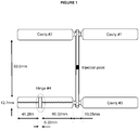
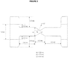
- a closure When a closure is a hinged closure, it comprises a hinged component and generally consists of at least two bodies which are connected by a thinner section that acts as a hinge allowing the at least two bodies to bend from an initially molded position.
- the thinner section may be continuous or web-like, wide or narrow.
- a useful closure for bottles, containers and the like is a hinged closure and may consist of two bodies joined to each other by at least one thinner bendable portion (e.g. the two bodies can be joined by a single bridging portion, or more than one bridging portion, or by a webbed portion, etc.).
- a first body may contain a dispensing hole and which may snap onto or screw onto a container to cover a container opening (e.g. a bottle opening) while a second body may serve as a snap on lid which may mate with the first body.
- caps and closures of which hinged caps and closures are a subset, can be made according to any known method, including for example injection molding and continuous compression molding techniques that are well known to persons skilled in the art.
- a closure (or cap) comprising the polyethylene composition is prepared with a process comprising at least one compression molding step and/or at least one injection molding step.
- Hinged closures and caps are well suited for sealing bottles, containers and the like, for examples bottles that may contain drinkable water, and other foodstuffs, including but not limited to liquids that are non-pressurized.
- the hinged closures and caps may also be used for sealing bottles containing drinkable water or non-carbonated beverages (e.g. juice).
- Other applications include hinged caps and closures for bottles and containers containing foodstuffs, such as for example ketchup bottles and the like.
- polyethylene compositions described herein are used in the formation of a hinged component.
- the hinged component can be a part of a cap or closure or it can be a cap or closure per se.
- the hinged component can be made according to any known method, including for example injection molding and compression molding techniques that are well known to persons skilled in the art.
- a hinged component comprising the polyethylene composition defined herein is prepared with a process comprising at least one compression molding step and/or at least one injection molding step.
- the polyethylene compositions described herein are used in a process to make a hinged component.
- Such processes include, for example, compression molding (or continuous compression molding) and injection molding.
- a hinged component is a component consisting of at least two bodies which are connected to one another through a flexible hinge.
- the flexible hinge may be a continuous, partial or segmented section (which is typically thinner than the two or more bodies), so as to act as a fulcrum or pivot point about which the two or more bodies may bend.
- the two or more bodies may bend about the flexible hinge from a molded position into a flexed position.
- hinged components include caps or closures having a single strap, dual strap, multi strap or butterfly strap designs such as, for example, those shown in U.S. Pat. Appl. Pub. No. 2013/0343808 (see for example Figures 3 to 13 therein).
- the hinged component is a hinged cap or closure, or the like for bottles, containers and the like.
- Caps and closures may be formed by continuous compression molding or by injection molding.
- Such closures include, for example, hinged caps, hinged screw caps, hinged snap-top caps, and hinged closures for bottles, containers and the like.
- a hinged component is a closure (or cap) comprising a hinge made of the same material as the rest of the closure (or cap).
- a hinged component is a hinged closure (or cap).
- a hinged component is a hinged closure (or cap) for bottles, containers and the like.
- a hinged component is a flip-top hinge closure, such as a flip-top hinge closure for use on a plastic ketchup bottle or similar containers containing foodstuffs.
- a closure When a closure is a hinged closure, it may comprise a hinged component and generally consists of at least two bodies which are connected by a thinner section that acts as a hinge allowing the at least two bodies to bend from an initially molded position.
- the thinner section may be continuous or web-like, wide or narrow.
- a useful hinged component is a hinged closure (for bottles, containers and the like) and may consist of two bodies joined to each other by at least one thinner bendable portion (e.g. the two bodies can be joined by a single bridging portion, or more than one bridging portion, or by a webbed portion, etc.).
- a first body may contain a dispensing hole and which may snap onto or screw onto a container to cover a container opening (e.g. a bottle opening) while a second body may serve as a snap on lid which may mate with the first body.
- Hinged caps and closures can be made according to any known method, including for example injection molding and compression molding techniques that are well known to persons skilled in the art.
- a closure (or cap) comprising the polyethylene composition is prepared with a process comprising at least one continuous compression molding step and/or at least one injection molding step.
- the hinged closures and caps of this disclosure may be used for sealing bottles, containers and the like, for example, bottles that may contain drinkable water, and other foodstuffs, including but not limited to liquids that are non-pressurized.
- the hinged closures and caps may also be used for sealing bottles containing drinkable water or non-carbonated beverages (e.g. juice).
- Other applications include hinged caps and closures for bottles and containers containing foodstuffs, such as for example ketchup bottles and the like.
- a hinged component has an average hinge life of at least 4100 cycles.
- a hinged component has an average hinge life of at least 4200 cycles.
- a hinged component has an average hinge life of at least 4500 cycles.
- a hinged component has an average hinge life of at least 4800 cycles.
- a hinged component has an average hinge life of at least 5000 cycles.
- a hinged component has an average hinge life of from about 4200 cycles to about 15,000 cycles.
- a hinged component has an average hinge life of from about 4200 cycles to about 10,000 cycles.
- a hinged component has an average hinge life of from about 4500 cycles to about 15,000 cycles.
- a hinged component has an average hinge life of from about 4500 cycles to about 10,000 cycles.
- Melt indexes, I 2 , I 5 , I 6 and I 21 for the polyethylene composition were measured according to ASTM D1238 (when conducted at 190°C, using a 2.16 kg, a 5 kg, a 6.48 kg and a 21 kg weight respectively).
- M n , M w , and M z were determined by high temperature Gel Permeation Chromatography with differential refractive index detection using universal calibration (e.g. ASTM -D6474-99).
- GPC data was obtained using an instrument sold under the trade name "Waters 150c", with 1,2,4-trichlorobenzene as the mobile phase at 140°C. The samples were prepared by dissolving the polymer in this solvent and were run without filtration.
- Molecular weights are expressed as polyethylene equivalents with a relative standard deviation of 2.9% for the number average molecular weight (“Mn”) and 5.0% for the weight average molecular weight (“Mw”).
- the molecular weight distribution is the weight average molecular weight divided by the number average molecular weight, M W /M n .
- the z-average molecular weight distribution is M z /M n .
- Polymer sample solutions (1 to 2 mg/mL) were prepared by heating the polymer in 1,2,4-trichlorobenzene (TCB) and rotating on a wheel for 4 hours at 150°C in an oven.
- TCB 1,2,4-trichlorobenzene
- the antioxidant 2,6-di-tert-butyl-4-methylphenol (BHT) was added to the mixture in order to stabilize the polymer against oxidative degradation.
- the BHT concentration was 250 ppm.
- Sample solutions were chromatographed at 140°C on a PL 220 high-temperature chromatography unit equipped with four SHODEX® columns (HT803, HT804, HT805 and HT806) using TCB as the mobile phase with a flow rate of 1.0 mL/minute, with a differential refractive index (DRI) as the concentration detector.
- BHT was added to the mobile phase at a concentration of 250 ppm to protect the columns from oxidative degradation.
- the sample injection volume was 200 mL.
- the raw data were processed with CIRRUS® GPC software.
- the columns were calibrated with narrow distribution polystyrene standards.
- the polystyrene molecular weights were converted to polyethylene molecular weights using the Mark-Houwink equation, as described in the ASTM standard test method D6474.
- the short chain branch frequency (SCB per 1000 carbon atoms) of the polyethylene composition was determined by Fourier Transform Infrared Spectroscopy (FTIR) as per the ASTM D6645-01 method.
- FTIR Fourier Transform Infrared Spectroscopy
- a Thermo-Nicolet 750 Magna-IR Spectrophotometer equipped with OMNIC® version 7.2a software was used for the measurements.
- Unsaturations in the polyethylene composition were also determined by Fourier Transform Infrared Spectroscopy (FTIR) as per ASTM D3124-98.
- Comonomer content can also be measured using 13 C NMR techniques as discussed in Randall, Rev. Macromol. Chem. Phys., C29 (2&3), p 285 ; U.S. Pat. No. 5,292,845 and WO 2005/121239 .
- Polyethylene composition density (g/cm 3 ) was measured according to ASTM D792.
- Hexane extractables were determined according to ASTM D5227.
- Shear viscosity was measured by using a Kayeness WinKARS Capillary Rheometer (model # D5052M-115). For the shear viscosity at lower shear rates, a die having a die diameter of 0.06 inch and L/D ratio of 20 and an entrance angle of 180 degrees was used. For the shear viscosity at higher shear rates, a die having a die diameter of 0.012 inch and L/D ratio of 20 was used.
- a solubility distribution curve is first generated for the polyethylene composition. This is accomplished using data acquired from the TREF technique. This solubility distribution curve is a plot of the weight fraction of the copolymer that is solubilized as a function of temperature. This is converted to a cumulative distribution curve of weight fraction versus comonomer content, from which the CDBI(50) is determined by establishing the weight percentage of a copolymer sample that has a comonomer content within 50% of the median comonomer content on each side of the median (See WO 93/03093 and U.S. Patent 5,376,439 ). The CDBI(25) is determined by establishing the weight percentage of a copolymer sample that has a comonomer content within 25% of the median comonomer content on each side of the median
- the temperature rising elution fractionation (TREF) method used herein was as follows. Polymer samples (50 to 150 mg) were introduced into the reactor vessel of a crystallization-TREF unit (Polymer Char). The reactor vessel was filled with 20 to 40 ml 1,2,4-trichlorobenzene (TCB), and heated to the desired dissolution temperature (e.g., 150°C) for 1 to 3 hours. The solution (0.5 to 1.5 ml) was then loaded into the TREF column filled with stainless steel beads. After equilibration at a given stabilization temperature (e.g., 110°C) for 30 to 45 minutes, the polymer solution was allowed to crystallize with a temperature drop from the stabilization temperature to 30°C (0.1 or 0.2°C/minute).
- TAB 1,2,4-trichlorobenzene
- the crystallized sample was eluted with TCB (0.5 or 0.75 mL/minute) with a temperature ramp from 30°C to the stabilization temperature (0.25 or 1.0°C/minute).
- the TREF column was cleaned at the end of the run for 30 minutes at the dissolution temperature.
- the data were processed using Polymer Char software, Excel spreadsheet and TREF software developed in-house.
- High temperature GPC equipped with an online FTIR detector was used to measure the comonomer content as the function of molecular weight.
- Plaques molded from the polyethylene compositions were tested according to the following ASTM methods: Bent Strip Environmental Stress Crack Resistance (ESCR) at Condition B at 100% IGEPAL at 50°C, ASTM D1693; notched Izod impact properties, ASTM D256; Flexural Properties, ASTM D 790; Tensile properties, ASTM D 638; Vicat softening point, ASTM D 1525; Heat deflection temperature, ASTM D 648.
- ESCR Bent Strip Environmental Stress Crack Resistance
- Dynamic mechanical analyses were carried out with a rheometer, namely Rheometrics Dynamic Spectrometer (RDS-II) or Rheometrics SR5 or ATS Stresstech, on compression molded samples under nitrogen atmosphere at 190°C, using 25 mm diameter cone and plate geometry.
- the oscillatory shear experiments were done within the linear viscoelastic range of strain (10% strain) at frequencies from 0.05 to 100 rad/s.
- the values of storage modulus (G'), loss modulus (G"), complex modulus (G*) and complex viscosity ( ⁇ *) were obtained as a function of frequency.
- the same rheological data can also be obtained by using a 25 mm diameter parallel plate geometry at 190oC under nitrogen atmosphere.
- Examples of the polyethylene compositions were produced in a dual reactor solution polymerization process in which the contents of the first reactor flow into the second reactor.
- This in-series "dual reactor” process produces an "in-situ” polyethylene blend (i.e., the polyethylene composition). Note, that when an in-series reactor configuration is used, un-reacted ethylene monomer, and un-reacted alpha-olefin comonomer present in the first reactor will flow into the downstream second reactor for further polymerization.
- an ethylene copolymer is nevertheless formed in second reactor due to the significant presence of un-reacted 1-octene flowing from the first reactor to the second reactor where it is copolymerized with ethylene.
- Each reactor is sufficiently agitated to give conditions in which components are well mixed.
- the volume of the first reactor was 12 liters and the volume of the second reactor was 22 liters. These are the pilot plant scales.
- the first reactor was operated at a pressure of 10500 to 35000 kPa and the second reactor was operated at a lower pressure to facilitate continuous flow from the first reactor to the second.
- the solvent employed was methylpentane. The process operates using continuous feed streams.
- a cyclopentadienide ligand e.g., Cp
- activatable ligands such as but not limited to chloride ligands
- a boron based co-catalyst (e.g., Ph 3 CB(C 6 F 5 ) 4 ) was used in approximately stoichiometric amounts relative to the titanium complex.
- Commercially available methylaluminoxane (MAO) was included as a scavenger at an AI:Ti of about 40:1.
- AI:Ti of about 40:1.
- 2,6-di-tert-butylhydroxy-4-ethylbenzene was added to scavenge free trimethylaluminum within the MAO in a ratio of AI:OH of about 0.5:1.
- Examples 1-6 which are inventive are made using a single site phosphinimine catalyst in a dual reactor solution process as described above. Each has a melt index I 2 of greater than 10 g/10min, a SCB1/SCB2 ratio of greater than 1.0 and a Mz value of less than 300,000. Examples 1-6 also have an optimized melt flow ratio I 21 /I 2 falling within a range of from 24 to 38.
- the polyethylene compositions of Example 7, 8 and 9 are comparative and each has a melt index, I 2 of greater than 10 g/10min, a SCB1 /SCB2 of greater than 1.0 and a and a Mz value of less than 300,000. However, in contrast to Examples 1-6, Examples 7-9 have a melt flow ratio I 21 /I 2 of greater than 41.
- the polyethylene compositions of Examples 7- 9 are also made using a single site phosphinimine catalyst in a dual reactor solution process as described above.
- the polymerization conditions used to make the polyethylene compositions are provided in Table 1.
- Table 2 shows polymer composition properties and pressed polymer plaque data.
- the model takes for input the flow of several reactive species (e.g. catalyst, monomer such as ethylene, comonomer such as 1-octene, hydrogen, and solvent) going to each reactor, the temperature (in each reactor), and the conversion of monomer (in each reactor), and calculates the polymer properties (of the polymer made in each reactor, i.e., the first and second ethylene copolymers) using a terminal kinetic model for continuously stirred tank reactors (CSTRs) connected in series.
- CSTRs continuously stirred tank reactors
- the terminal kinetic model for polymerization includes reaction rate equations for activation, initiation, propagation, chain transfer, and deactivation pathways. This model solves the steady-state conservation equations (e.g., the total mass balance and heat balance) for the reactive fluid which comprises the reactive species identified above.
- ⁇ i the mass flow rate of stream i (inlet or outlet)
- ⁇ H i the difference in enthalpy of stream i versus a reference state
- q Rx the heat released by reaction(s)
- V the reactor volume
- ⁇ the work input (i.e., agitator)
- Q ⁇ the heat input/loss.
- the catalyst concentration input to each reactor is adjusted to match the experimentally determined ethylene conversion and reactor temperature values in order solve the equations of the kinetic model (e.g., propagation rates, heat balance and mass balance).
- the H 2 concentration input to each reactor may be likewise adjusted so that the calculated molecular weight distribution of a polymer made over both reactors (and, hence, the molecular weight of polymer made in each reactor) matches that which is observed experimentally.
- k p 12 is the propagation rate constant for adding monomer 2 to a growing polymer chain ending with monomer 1
- [ m 1 ] is the molar concentration of monomer 1 (ethylene) in the reactor
- [ m 2 ] is the molar concentration of monomer 2 (1-octene) in the reactor
- k tm 12 the termination rate constant for chain transfer to monomer 2
- the weight fraction of material made in each reactor is determined from knowing the mass flow of monomer and comonomer into each reactor along with knowing the conversions for monomer and comonomer in each reactor.
- the comonomer content in the polymer product (in each reactor) may also be calculated using the terminal kinetic model and long chain approximations discussed above (see A. Hamielec, J. MacGregor, and A. Penlidis. Comprehensive Polymer Science and Supplements, volume 3, chapter Copolymerization, page 17, Elsevier, 1996 ).
- the molar ratio of ethylene to comonomer in the polymer ( Y ) can be estimated knowing the reactivity ratio r 1 of the catalsyt system and knowing the ethylene conversion in the reactor ( Q m 1 ).
- a quadratic equation can be derived using the May and Lewis equation for instantaneous comonomer incorporation (see “ Copolymerization” by A. Hamielec, J. MacGregor, and A. Penlidis in Comprehensive Polymer Science and Supplements, Volume 3, Chapter 2, page 17, Elsevier, 1996 ) and solving the mass balance around the reaction.
- Y is the molar ratio of ethylene to 1-octene in the polymer
- y is the mass flow ratio of 1-octene to ethylene going the reactor
- Q m 1 is the ethylene monomer fractional conversion.
- the overall branching frequency distribution (BFD) of the ethylene composition can be calculated by knowing the molecular weight distribution and weight fraction of polymer made in each reactor, and the average branching frequency (BF) of the ethylene copolymer made in each reactor.
- the fraction of polymer made in each reactor can be calculated from the experimental mass flows and conversion of monomer and comonomer in each reactor.
- BF MW is the branching at molecular weight (MW)
- w R 1 and w R 2 are the weight fraction of polymer made in Reactor 1 and Reactor 2
- BF R 1 and BF R 2 are the average branching frequency of polymer made in R1 and R2 (from Equations 9 and 10)
- F 1 ( MW R 1 ) and F 2 ( MW R 2 ) are Flory distribution function from Reactor 1 and Reactor 2.
- the key resin parameters which are obtained from the above described kinetic model are the molecular weights Mn, Mw and Mz, the molecular weight distributions M W /M n and Mz/Mw and the branching frequency (SCB/1000 Cs).
- hinged component mold A four-cavity hinged component mold was used which can produce four types of hinged component. These four hinged components may have different geometries and dimensions which are designed to simulate the hinge sections of typical hinged caps and closures. Among the four types of hinged components, hinge component, "hinge number 4" was used in the present analysis. The design and dimensions of hinge No. 4 are provided in Figures 1-3 .
- Comp. 7 Comp. 8 Comp. 9 Part Weight (g) 10.0 10.1 10.0 Injection Speed (mm/s) 135 135 135 Cycle time (s) 19.568 19.569 19.568 Filling time (s) 0.2210 0.2210 0.2210 Dosing time (s) 4.163 4.206 4.190 Minimum Cushion (mm) 5.729 5.261 5.586 Filling peak pressure (psi) 13310.9 13738.3 13362.8 Full peak pressure (psi) 13310.9 13738.3 13362.8 Hold end position (mm) 5.729 5.261 5.586 Hold pressure set (psi) 12500 13500 13500 13500 Clamp force (ton) 50.06 50.12 50.46 Fill start position (mm) 38.506 38.506 38.506 Dosing back pressure (psi) 1576.7 1684 1629.1 Pack pressure (psi) 9312.3 9582 9380.8 Filling time 1 (s) 0.224 0.224 0.224 Temperature zone 1 (°C) 230 230 230 Temperatur
- the hinge number 4 was isolated from the mold and used directly in a so called "hinge component life test".
- the hinge dimensions were as shown in Figures 1-3 .
- the test involves bending the hinged component from an unstressed, unbent position about its hinge axis and through an angle of about 130o and then allowing the hinged component to return to an unstressed position.
- the device used to carry out the testing in shown in Figures 4 and 5 .
- the device 1 comprises a pair of rotating end disks 2 which encompass a flat plate area 3 between them.
- the plate has a rounded edge or lip.
- On the top of the plate area are fixed a series of clamps 5 positioned adjacent to the plate edge.
- the clamps secure one end of the hinged component on to the plate surface, with the component's hinge axis (or desired location of bending) aligned with the plate edge (note: with reference to Figures 1 and 5 , the clamp is placed at the longitudinal mid-point of the short side of the hinge component, hinge number 4, shown as element 6 in Figures 4 and 5 ).
- the hinged component is clamped on one side of the device as shown in Figures 4 and 5 with the hinge axis aligned with the plate edge over which it is to be bent.
- the other end of the hinged component extends between two lateral bars 4 and 7 which are positioned beyond the hinge axis and which ride over (bar 7 ) and under (bar 4 ) the unclamped end of the hinged component.
- a second set of bars 8 and 9 help to provide structural rigidity to the device.
- the bars are attached to the rotating end disks, which when rotated, force the upper bar 7 down on the unclamped end of the hinged component bending the hinged component about its hinge axis through an angle of about 130o.
- This downward bending motion followed by removal of bending stress is considered one cycle (note: after the first bend, the hinge component does not fully return to its original un-bent position).
- the hinged component is subject to repeated cycles of being bent then allowed to relax.
- the hinge component testing device was operated at a bending frequency of 45 cycles per minute. The cycles were repeated until the hinged component failed.
- An electronic counter for example one which has an actuator that comes in contact with a protuberance on the outside surface of an end disk, may be used in conjunction with the device.
- a video camera may also be mounted near the device to record the exact cycle count at which a hinge component break occurs.
- hinged components being made of the same polymer composition were tested at the same time (see Figures 4 and 5 ).
- a total of 20 to 30 hinge component specimens were tested for a given polymer composition.
- the average number of cycles before the hinge failed and the standard deviations of the hinge life were then calculated and reported for a given polymer composition.
- the hinge component life test then reports the average numbers of cycles endured by a hinged component made from a given polymer composition before failure.
- the rotating end disks may be rotated manually or as show in Figure 5 they may be driven by a hydraulic piston, 10. The results of such testing is provided in Table 6.
- hinge life cycle data for hinged components made from the polyethylene compositions of Examples 1-9 are given in Table 6. TABLE 6 Hinge Life in No. of Cycles Example No. Inv. 1 Inv. 2 Inv. 3 Inv. 4 Inv. 5 Inv. 6 Comp. 7 Comp. 8 Comp. 9 Average 8197 8148 6669 5368 4880 6193 2304 3628 4015 Standard Deviation 1049 1495 663 591 430 664 212 405 614 Sample Size, n 20 20 20 20 20 20 20 20 20 20 20 20 20 20 20 20 20 20 20 20 20 20 20 20 20 20 20 20 20 20 20 20 20 20 20 20 20 20 20 20 20 20 20 20 20 20 20 20 20 20 20 20 20 20 20 20 20 20 20 20 20 20 20 20 20 20 20 20 20 20 20 20 20 20 20 20 20 20 20 20 20 20 20 20 20 20 20 20 20 20 20 20 20 20 20 20 20 20 20 20 20 20 20 20 20 20 20 20 20 20 20 20 20 20 20 20 20 20 20 20 20 20 20 20 20 20 20 20 20 20 20 20 20
- the fact that the hinge life cycle performance drops off when the polymer used has a higher melt flow ratio is surprising.
- a melt flow ratio (I 21 /I 2 ) in the range of from about 24 to about 38 would appear to be ideal.
- hinged components made from a polyethylene composition comprising a first ethylene copolymer and a second ethylene copolymer.
- the hinged components which have good hinge life cycle values may for example be hinged closures made commercially by compression molding or injection molding.
Description
- The present disclosure is directed to hinged components made from polyethylene compositions which comprise a first ethylene copolymer and a second ethylene copolymer. The polyethylene compositions have an optimized set of properties making them particularly suitable for applications in hinged components such as for example hinged closures for bottles.
-
U.S. Pat. Appl. Pub. No. 2014/0275426 discloses a polymer blend comprising a linear low density polyethylene copolymer and a high density polyethylene homopolymer. The blend performed well in polymer bent strip testing. -
U.S. Pat. No. 9,273,199 U.S. Pat. Appl. Pub. No. 2013/0343808 disclose that a blend comprising two high density polyethylene components can be injected molded into hinged closures having a hinge performance which is comparable to that of hinges made from polypropylene. -
U.S. Pat. No. 9,074,082 U.S. Pat. Appl. Pub. No. 2015/0259519 discloses that the same compositions are useful in forming hinged closures. - We now report that hinged components having improved hinge life cycle values can be made using an optimized polyethylene composition having a molecular weight distribution Mw/Mn, of from 2.0 to 7.0; a density of at least 0.949 g/cm3; a melt index I2 of from greater than 10.0 g/10min to 20.0 g/10min, a Z-average molecular weight Mz, of less than 300,000; and a melt flow ratio I21/I2, of from 24 to 38.
- One embodiment of the disclosure is a hinged component comprising a polyethylene composition, the polyethylene composition comprising:
- (1) about 10 to about 70 wt% of a first ethylene copolymer having a melt index I2, of from 0.1 to 10 g/10min; a molecular weight distribution Mw/Mn, of less than 3.0; and a density of from 0.930 to 0.960 g/cm3; and
- (2) about 90 to about 30 wt% of a second ethylene copolymer having a melt index I2, of from 50 to 10,000 g/10min; a molecular weight distribution Mw/Mn, of less than 3.0; and a density higher than the density of the first ethylene copolymer, but less than 0.966 g/cm3;
- One embodiment of the disclosure is a process for preparing a hinged component wherein the process comprises at least one compression molding or injection molding step and wherein the hinged component comprises a polyethylene composition, the polyethylene composition comprising:
- (1) about 10 to about 70 wt% of a first ethylene copolymer having a melt index I2, of from 0.1 to 10 g/10min; a molecular weight distribution Mw/Mn, of less than 3.0; and a density of from 0.930 to 0.960 g/cm3; and
- (2) about 90 to about 30 wt% of a second ethylene copolymer having a melt index I2, of from 50 to 10,000 g/10min; a molecular weight distribution Mw/Mn, of less than 3.0; and a density higher than the density of the first ethylene copolymer, but less than 0.966 g/cm3;
- In one embodiment of the disclosure, a hinged component has a hinge life of more than 4200 cycles.
-
-
Figure 1 shows an illustration of a four cavity hinge component mold along with some dimensions of the hinge component, "hinge no. 4". Hinge component, "hinge no. 4" was used for hinge component life cycle testing. -
Figure 2 shows an expanded perspective view of the hinge area of the hinge component, "hinge no. 4" along with some of its dimensions. -
Figure 3 shows an expanded side view illustration of the hinge component, "hinge no. 4" along with some dimensions and the angle, α which is equal to 15°C. -
Figure 4 shows a front perspective view of thedevice 1, used to measure the average hinge life values of a hinged component. -
Figure 5 shows a side perspective view of thedevice 1, used to measure the average hinge life values of a hinged component. - The present disclosure relates to polyethylene compositions that are useful in the manufacture of molded hinged components such as hinged closures.
- In an embodiment of the disclosure the polyethylene compositions are composed of at least two ethylene copolymer components: a first ethylene copolymer and a second ethylene copolymer.
- It should be understood that any numerical range recited herein is intended to include all sub-ranges subsumed therein. For example, a range of "1 to 10" is intended to include all sub-ranges between and including the recited minimum value of 1 and the recited maximum value of 10; that is, having a minimum value equal to or greater than 1 and a maximum value of equal to or less than 10. Because the disclosed numerical ranges are continuous, they include every value between the minimum and maximum values.
- The terms "cap" and "closure" are used interchangeably in the current disclosure, and both connote any suitably shaped molded article for enclosing, sealing, closing or covering etc., a suitably shaped opening, a suitably molded aperture, an open necked structure or the like used in combination with a container, a bottle, a jar and the like.
- It is well known that metallocene catalysts and other so called "single site catalysts" generally incorporate comonomer more evenly than traditional Ziegler-Natta catalysts when used for catalytic ethylene copolymerization with alpha olefins. This fact is often demonstrated by measuring the composition distribution breadth index (CDBI) for corresponding ethylene copolymers. The composition distribution of a polymer can be characterized by the short chain distribution index (SCDI) or composition distribution breadth index (CDBI). The definition of composition distribution breadth index (CDBI(50)) can be found in
PCT publication WO 93/03093 U.S. Pat. No. 5,206,075 . The CDBI(50) is conveniently determined using techniques which isolate polymer fractions based on their solubility (and hence their comonomer content). For example, temperature rising elution fractionation (TREF) as described by Wild et al. J. Poly. Sci., Poly. Phys. Ed. Vol. 20, p441, 1982 or inU.S. Pat. No. 4,798,081 can be employed. From the weight fraction versus composition distribution curve, the CDBI(50) is determined by establishing the weight percentage of a copolymer sample that has a comonomer content within 50% of the median comonomer content on each side of the median. Alternatively, the CDBI(25), which is sometimes used in the art, is determined by establishing the weight percentage of a copolymer sample that has a comonomer content within 25% of the median comonomer content on each side of the median. - In an embodiment of the disclosure, the first ethylene copolymer of the polyethylene composition has a density of from about 0.930 g/cm3 to about 0.960 g/cm3; a melt index, I2, of more than 0.1 g/10 min; a molecular weight distribution, Mw/Mn, of below about 3.0 and a weight average molecular weight Mw, that is greater than the Mw of the second ethylene copolymer. In one embodiment, the weight average molecular weight Mw, of the first ethylene copolymer is at least 50,000 g/mol.
- By the term "ethylene copolymer" it is meant that the copolymer comprises both polymerized ethylene and at least one polymerized alpha-olefin comonomer, with polymerized ethylene being the majority species.
- In an embodiment of the disclosure, the first ethylene copolymer is made with a single site catalyst, such as, for example, a phosphinimine catalyst.
- In an embodiment of the disclosure, the comonomer (i.e., alpha-olefin) content in the first ethylene copolymer is from about 0.05 to about 3.0 mol% as measured by 13C NMR, or FTIR or GPC-FTIR methods, or as calculated from a reactor model (see the Examples section). The comonomer is one or more suitable alpha olefin, which include, but are not limited to, 1-butene, 1-hexene, 1-octene and the like. In one embodiment the alpha olefin is 1-octene.
- In an embodiment of the disclosure, the short chain branching in the first ethylene copolymer is from about 0.25 to about 15 short chain branches per thousand carbon atoms (SCB1/1000Cs). In further embodiments of the disclosure, the short chain branching in the first ethylene copolymer can be from 0.25 to 10, or from 0.25 to 7.5, or from 0.25 to 5, or from 0.25 to 3 branches per thousand carbon atoms (SCB1/1000Cs). The short chain branching is the branching due to the presence of alpha-olefin comonomer in the ethylene copolymer and will for example have two carbon atoms for a 1-butene comonomer, or four carbon atoms for a 1-hexene comonomer, or six carbon atoms for a 1-octene comonomer, etc. The comonomer is one or more suitable alpha-olefin, which include, but are not limited to, 1-butene, 1-hexene, 1-octene and the like. In one embodiment the alpha olefin is 1-octene.
- In an embodiment of the disclosure, the comonomer content in the first ethylene copolymer is greater than comonomer content of the second ethylene copolymer (as reported, for example, in mol%).
- In an embodiment of the disclosure, the amount of short chain branching in the first ethylene copolymer is greater than the amount of short chain branching in the second ethylene copolymer (as reported in short chain branches, SCB per thousand carbons in the polymer backbone, 1000Cs).
- In some embodiments of the disclosure the melt index, I2 of the first ethylene copolymer can be from 0.1 to 10 g/10min and including narrower ranges within this range and any numbers encompassed by these ranges. For example, the melt index I2 of the first ethylene composition can be from above 0.1 to below 10 g/10min, or can be from 0.1 to 7.5 g/10min, or from 0.1 to 5.0 g/10min, or from 0.1 to 3.0 g/10min, or from 0.1 to 2.5 g/10min, or from 0.1 to 2.0 g/10min, or from 0.1 to 1.75 g/10min, or from 0.1 to 1.5 g/10min, or from 0.1 to 1.0 g/10min.
- In an embodiment of the disclosure, the first ethylene copolymer has a weight average molecular weight Mw of from about 50,000 to about 225,000 g/mol including narrower ranges and any numbers encompassed by these ranges. For example, in another embodiment of the disclosure, the first ethylene copolymer has a weight average molecular weight Mw of from about 75,000 to about 200,000. In further embodiments of the disclosure, the first ethylene copolymer has a weight average molecular weight Mw of from about 75,000 to about 175,000, or from about 85,000 to about 150,000, or from about 100,000 to about 150,000.
- In embodiments of the present disclosure, the density of the first ethylene copolymer is from 0.929 to 0.960 g/cm3 or can be a narrower range within this range and any numbers encompassed by these ranges. For example, in further embodiments of the disclosure, the density of the first ethylene copolymer can be from 0.930 to 0.960 g/cm3, or can be from 0.932 to 0.960 g/cm3, or from 0.930 to 0.952 g/cm3, or from 0.932 to 0.952 g/cm3, or from 0.930 to 0.950 g/cm3, or from 0.932 to 0.950 g/cm3, or from 0.930 to 0.948 g/cm3, or from 0.932 to 0.948 g/cm3.
- In embodiments of the disclosure, the first ethylene copolymer has a molecular weight distribution Mw/Mn of < 3.0, or ≤ 2.7, or < 2.7, or ≤ 2.5, or < 2.5, or ≤ 2.3, or from 1.8 to 2.3.
- In an embodiment of the disclosure, the first ethylene copolymer of the polyethylene composition is produced with a single site catalyst and has a weight average molecular weight Mw, of at least 50,000 g/mol; a molecular weight distribution, Mw/Mn, of less than 3.0 and a density of from 0.936 to 0.950 g/cm3.
- In an embodiment of the disclosure, a single site catalyst which gives an ethylene copolymer having a CDBI(50) of at least 65% by weight, or at least 70%, or at least 75%, or at least 80%, or at least 85%, during solution phase polymerization in a single reactor, is used in the preparation of the first ethylene copolymer.
- In an embodiment of the present disclosure, the first ethylene copolymer is ethylene copolymer which has a CDBI(50) of greater than about 60% by weight, or greater than about 65%, or greater than about 70%, or greater than about 75%, or greater than about 80%, or greater than about 85%.
- In an embodiment of the disclosure, the first ethylene copolymer comprises from about 10 to about 70 weight percent (wt%) of the total weight of the first and second ethylene copolymers. In an embodiment of the disclosure, the first ethylene copolymer comprises from 20 to about 60 weight percent (wt%) of the total weight of the first and second ethylene copolymers. In an embodiment of the disclosure, the first ethylene copolymer comprises from about 25 to about 60 weight percent (wt%) of the total weight of the first and second ethylene copolymers. In an embodiment of the disclosure, the first ethylene copolymer comprises from about 30 to about 60 weight percent (wt%) of the total weight of the first and second ethylene copolymers. In an embodiment of the disclosure, the first ethylene copolymer comprises from about 40 to about 50 weight percent (wt%) of the total weight of the first and second ethylene copolymers.
- In an embodiment of the disclosure, the second ethylene copolymer of the polyethylene composition has a density below 0.967 g/cm3 but which is higher than the density of the first ethylene copolymer; a melt index I2, of from about 50 to 10,000 g/10min; a molecular weight distribution, Mw/Mn, of below about 3.0 and a weight average molecular weight Mw that is less than the Mw of the first ethylene copolymer. In one embodiment, the weight average molecular weight, Mw of the second ethylene copolymer will be below 45,000 g/mole.
- In an embodiment of the disclosure, the second ethylene copolymer is made with a single site catalyst, such as for example a phosphinimine catalyst.
- In an embodiment of the disclosure, the comonomer content in the second ethylene copolymer is from about 0.05 to about 3 mol% as measured by 13C NMR, or FTIR or GPC-FTIR methods, or as calculated from a reactor model (see Examples section). The comonomer is one or more suitable alpha olefins, which include, but are not limited to, 1-butene, 1-hexene, 1-octene and the like. In one embodiment the alpha olefin is 1-octene.
- In an embodiment of the disclosure, the short chain branching in the second ethylene copolymer can be from about 0.10 to about 15 short chain branches per thousand carbon atoms (SCB1/1000Cs). In further embodiments of the disclosure, the short chain branching in the first ethylene copolymer can be from 0.10 to 10, or from 0.10 to 7.5, or from 0.10 to 5, or from 0.15 to 5, or from 0.10 to 3, or from 0.15 to 3, or from 0.20 to 5, or from 0.20 to 3, or from 0.25 to 5, or from 0.25 to 3 branches per thousand carbon atoms (SCB1/1000Cs). The short chain branching is the branching due to the presence of alpha-olefin comonomer in the ethylene copolymer and will for example have two carbon atoms for a 1 -butene comonomer, or four carbon atoms for a 1-hexene comonomer, or six carbon atoms for a 1-octene comonomer, etc. The comonomer is one or more suitable alpha olefin. Examples of alpha olefins include, but are not limited to 1-butene, 1-hexene, 1-octene and the like. In one embodiment the alpha olefin is 1-octene.
- In an embodiment of the disclosure, the comonomer content in the second ethylene copolymer is less than the comonomer content of the first ethylene copolymer (as reported for example in mol%).
- In an embodiment of the disclosure, the amount of short chain branching in the second ethylene copolymer is less than the amount of short chain branching in the first ethylene copolymer (as reported in short chain branches, SCB per thousand carbons in the polymer backbone, 1000Cs).
- In an embodiment of the present disclosure, the density of the second ethylene copolymer is less than 0.968 g/cm3. In another embodiment of the disclosure, the density of the second ethylene copolymer is less than 0.967 g/cm3. In another embodiment of the disclosure, the density of the second ethylene copolymer is less than 0.966 g/cm3. In another embodiment of the disclosure, the density of the second ethylene copolymer is less than 0.965 g/cm3. In an embodiment of the disclosure, the density of the second ethylene copolymer is from 0.952 to 0.967 g/cm3 or can be a narrower range within this range, including all the numbers encompassed within these ranges. In further embodiments, the density of the second ethylene copolymer is from 0.952 to 0.967 g/cm3, or from 0.952 to 0.965 g/cm3, or from 0.953 to 0.965 g/cm3, or from 0.954 to 0.965 g/cm3, or from 0.952 to less than 0.965 g/cm3, or from 0.954 to less than 0.965 g/cm3.
- In an embodiment of the present disclosure, the second ethylene copolymer has a density which is higher than the density of the first ethylene copolymer, but less than about 0.037 g/cm3 higher than the density of the first ethylene copolymer. In an embodiment of the disclosure, the second ethylene copolymer has a density which is higher than the density of the first ethylene copolymer, but less than about 0.035 g/cm3 higher than the density of the first ethylene copolymer. In another embodiment of the disclosure, the second ethylene copolymer has a density which is higher than the density of the first ethylene copolymer, but less than about 0.030 g/cm3 higher than the density of the first ethylene copolymer. In still another embodiment of the disclosure, the second ethylene copolymer has a density which is higher than the density of the first ethylene copolymer, but less than about 0.027 g/cm3 higher than the density of the first ethylene copolymer. In still another embodiment of the disclosure, the second ethylene copolymer has a density which is higher than the density of the first ethylene copolymer, but less than about 0.025 g/cm3 higher than the density of the first ethylene copolymer.
- In an embodiment of the disclosure, the second ethylene copolymer has a weight average molecular weight Mw of less than 45,000 g/mol. In another embodiment of the disclosure, the second ethylene copolymer has a weight average molecular weight Mw of from about 7,500 to about 40,000. In further embodiments of the disclosure, the second ethylene copolymer has a weight average molecular weight Mw of from about 9,000 to about 35,000, or from about 10,000 to about 30,000, or from about 10,000 to 25,000.
- In embodiments of the disclosure, the second ethylene copolymer has a molecular weight distribution (Mw/Mn) of <3.0, or ≤ 2.7, or < 2.7, or ≤ 2.5, or < 2.5, or ≤ 2.3, or from 1.8 to 2.3.
- In an embodiment of the disclosure, the melt index I2 of the second ethylene copolymer can be from 50 to 10,000 g/10min. In another embodiment of the disclosure, the melt index I2 of the second ethylene copolymer can be from 50 to 5,000 g/10min. In another embodiment of the disclosure, the melt index I2 of the second ethylene copolymer can be from 50 to 2,500 g/10min. In another embodiment of the disclosure, the melt index I2 of the second ethylene copolymer can be from 100 to 10,000 g/10min. In yet another embodiment of the disclosure, the melt index I2 of the second ethylene copolymer can be from 100 to 5,000 g/10min. In yet another embodiment of the disclosure, the melt index I2 of the second ethylene copolymer can be from 100 to 2,500 g/10min. In yet another embodiment of the disclosure, the melt index I2 of the second ethylene copolymer can be from 100 to 1,500 g/10min. In yet another embodiment of the disclosure, the melt index I2 of the second ethylene copolymer can be greater than 50, but less than 5,000 g/10min. In still yet another embodiment of the disclosure, the melt index I2 of the second ethylene copolymer can be greater than 100, but less than 3,000 g/10min. In still yet another embodiment of the disclosure, the melt index I2 of the second ethylene copolymer can be greater than 100, but less than 1,500 g/10min.
- In an embodiment of the disclosure, the melt index I2 of the second ethylene copolymer is greater than 50 g/10min. In an embodiment of the disclosure, the melt index I2 of the second ethylene copolymer is greater than 100 g/10min. In an embodiment of the disclosure, the melt index I2 of the second ethylene copolymer is greater than 300 g/10min. In an embodiment of the disclosure, the melt index I2 of the second ethylene copolymer is greater than 500 g/10min. In an embodiment of the disclosure, the melt index I2 of the second ethylene copolymer is greater than 1,000 g/10min.
- In an embodiment of the disclosure, the second ethylene copolymer of the polyethylene composition is made with a single site catalyst and has a weight average molecular weight, Mw, of at most 45,000; a molecular weight distribution, Mw/Mn, of less than 3.0 and a density higher than the density of said first ethylene copolymer, but less than 0.967 g/cm3.
- In an embodiment of the disclosure, a single site catalyst which gives an ethylene copolymer having a CDBI(50) of at least 65% by weight, or at least 70%, or at least 75%, or at least 80%, or at least 85%, during solution phase polymerization in a single reactor, is used in the preparation of the second ethylene copolymer.
- In an embodiment of the present disclosure, the second ethylene copolymer has a CDBI(50) of greater than about 60% by weight, or greater than about 65%, or greater than about 70%, or greater than about 75%, or greater than about 80%, or greater than about 85%.
- In an embodiment of the disclosure, the second ethylene copolymer comprises from about 90 to about 30 wt% of the total weight of the first and second ethylene copolymers. In an embodiment of the disclosure, the second ethylene copolymer comprises from about 80 to about 40 wt% of the total weight of the first and second ethylene copolymers. In an embodiment of the disclosure, the second ethylene copolymer comprises from about 75 to about 40 wt% of the total weight of the first and second ethylene copolymers. In an embodiment of the disclosure, the second ethylene copolymer comprises from about 70 to about 40 wt% of the total weight of the first and second ethylene copolymers. In an embodiment of the disclosure, the second ethylene copolymer comprises from about 60 to about 50 wt% of the total weight of the first and second ethylene copolymers.
- In embodiments of the disclosure, the melt index I2 of the second ethylene copolymer is at least 50 times, or at least 100 times, or at least 1,000 times the melt index I2 of the first ethylene copolymer.
- In one embodiment the polyethylene composition will contain a first ethylene copolymer and a second ethylene copolymer (as defined herein).
- In some embodiments of the disclosure, the polyethylene composition has a unimodal, broad unimodal, bimodal or multimodal molecular weight distribution as determined by gel permeation chromatography.
- In an embodiment of the disclosure, the polyethylene composition that comprises a first ethylene copolymer and a second ethylene copolymer (as defined above) will have a ratio (SCB1/SCB2) of the number of short chain branches per thousand carbon atoms in the first ethylene copolymer (i.e., SCB1) to the number of short chain branches per thousand carbon atoms in the second ethylene copolymer (i.e., SCB2) of greater than 1.0 (i.e., SCB1 / SCB2 > 1.0).
- In further embodiments of the disclosure, the ratio of the short chain branching in the first ethylene copolymer (SCB1) to the short chain branching in the second ethylene copolymer (SCB2) is at least 1.25. In still another embodiment of the disclosure, the ratio of the short chain branching in the first ethylene copolymer (SCB1) to the short chain branching in the second ethylene copolymer (SCB2) is at least 1.5.
- In embodiments of the disclosure, the ratio (SCB1/SCB2) of the short chain branching in the first ethylene copolymer (SCB1) to the short chain branching in the second ethylene copolymer (SCB2) will be from greater than 1.0 to about 12.0, or from greater than 1.0 to about 10, or from greater than 1.0 to about 7.0, or from greater than 1.0 to about 5.0, or from greater than 1.0 to about 3.0.
- In an embodiment of the disclosure, the polyethylene composition is bimodal as determined by gel permeation chromatography (GPC).
- A bimodal or multimodal polyethylene composition can be identified by using gel permeation chromatography (GPC). A GPC chromatograph may exhibit two or more component ethylene copolymers, where the number of component ethylene copolymers corresponds to the number of discernible peaks. One or more component ethylene copolymers may also exist as a hump, shoulder or tail relative to the molecular weight distribution of the other ethylene copolymer component. By the phrase "bimodal as determined by GPC", it is meant that in addition to a first peak, there will be a secondary peak or shoulder which represents a higher or lower molecular weight component (i.e., the molecular weight distribution, can be said to have two maxima in a molecular weight distribution curve). Alternatively, the phrase "bimodal as determined by GPC" connotes the presence of two maxima in a molecular weight distribution curve generated according to the method of ASTM D6474-99.
- In an embodiment of the disclosure, the polyethylene composition has a density of greater than or equal to 0.949 g/cm3, as measured according to ASTM D792; a melt index I2, of from greater than 10 g/10min to about 20 g/10 min, as measured according to ASTM D1238 (when conducted at 190°C, using a 2.16 kg weight); a molecular weight distribution, Mw/Mn, of from about 2.0 to about 7.0, a melt flow ratio I21/I2, of from 24 to 38, and a Z-average molecular weight Mz, of less than about 300,000.
- In embodiments of the disclosure, the polyethylene composition has a comonomer content of less than about 0.75 mol%, or less than about 0.70 mol%, or less than about 0.65 mol%, or less than about 0.60 mol%, or less than about 0.55 mol%, or less than about 0.50 mol% as measured by FTIR or 13C NMR methods, where the comonomer is one or more suitable alpha olefins, which include, but are not limited to, 1-butene, 1-hexene, 1-octene and the like. In one embodiment the alpha olefin is 1-octene.
- In an embodiment of the present disclosure, the polyethylene composition has a density of at least 0.949 g/cm3. In further embodiments of the disclosure, the polyethylene composition has a density of >0.950 g/cm3, or >0.951 g/cm3, or > 0.952 g/cm3, or > 0.953 g/cm3, or > 0.955 g/cm3.
- In an embodiment of the disclosure, the polyethylene composition has a density in the range of 0.949 to 0.970 g/cm3. In an embodiment of the disclosure, the polyethylene composition has a density in the range of 0.950 to 0.970 g/cm3. In an embodiment of the current disclosure, the polyethylene composition has a density in the range of 0.949 to 0.965 g/cm3. In an embodiment of the current disclosure, the polyethylene composition has a density in the range of 0.950 to 0.965 g/cm3. In an embodiment of the disclosure, the polyethylene composition has a density in the range of 0.949 to 0.962 g/cm3. In an embodiment of the disclosure, the polyethylene composition has a density in the range of 0.950 to 0.962 g/cm3. In an embodiment of the disclosure, the polyethylene composition has a density in the range of 0.949 to 0.960 g/cm3. In an embodiment of the disclosure, the polyethylene composition has a density in the range of 0.950 to 0.960 g/cm3. In an embodiment of the disclosure, the polyethylene composition has a density in the range of 0.949 to 0.959 g/cm3. In an embodiment of the disclosure, the polyethylene composition has a density in the range of 0.950 to 0.959 g/cm3.
- In an embodiment of the disclosure, the polyethylene composition has a melt index I2, of from greater than 10 g/10min to 22 g/10 min according to ASTM D1238 (when conducted at 190°C, using a 2.16 kg weight) and including narrower ranges within this range and all numbers encompassed by these ranges. For example, in further embodiments of the disclosure, the polyethylene composition has a melt index I2, of greater than 10 g/10min, but less than 22 g/10min, or from greater than 10 g/10min to 20.0 g/10min, or from 10.5 g/10min to 19.0 g/10min, or from 10.5 g/10min to 18.5 g/10min, or from 10.5 g/10min to 18.0 g/10min.
- In an embodiment of the disclosure, the polyethylene composition has a "high load" melt index I21 of at least about 150 g/10min according to ASTM D1238 (when conducted at 190°C, using a 21 kg weight). In another embodiment of the disclosure, the polyethylene composition has a high load melt index I21, of greater than about 200 g/10min. In another embodiment of the disclosure, the polyethylene composition has a high load melt index I21, of greater than about 250 g/10min. In another embodiment of the disclosure, the polyethylene composition has a high load melt index I21, of greater than about 300 g/10min.
- In an embodiment of the disclosure, the polyethylene composition has a high load melt index I21, of from 150 to 750 g/10min, or from 200 to 750 g/10min, or from 250 to 750 g/10min, or from 300 to 800 g0min, or from 300 to 750 g/10min.
- In an embodiment of the disclosure, the polyethylene composition has a number average molecular weight Mn, of below about 30,000 g/mol. In another embodiment of the disclosure, the polyethylene composition has a number average molecular weight Mn, of below about 25,000 g/mol. In yet another embodiment of the disclosure, the polyethylene composition has a number average molecular weight Mn, of below about 20,000 g/mol.
- In the present disclosure, the polyethylene composition has a molecular weight distribution Mw/Mn, of from 2.0 to 7.0 or a narrower range within this range, including all the numbers encompassed within these ranges. For example, in further embodiments of the disclosure, the polyethylene composition has molecular weight distribution Mw/Mn, of from 2.5 to 7.0, or from 2.0 to 6.0, or from 2.0 to 5.5, or from 2.0 to 5.0, or from 2.0 to 4.5, or from 2.0 to 4.0, or from 2.5 to 4.5, or from 2.5 to 4.0, or from 2.5 to 3.5, or from 3.0 to 5.5, or from 3.0 to 5.0, or from 3.0 to 4.5, or from 3.0 to 4.0.
- In an embodiment of the disclosure, the polyethylene composition has a Z-average molecular weight, Mz, of below about 300,000 g/mole. In another embodiment of the disclosure, the polyethylene composition has a Z-average molecular weight, Mz, of below about 250,000 g/mole. In yet another embodiment of the disclosure, the polyethylene composition has a Z-average molecular weight, Mz, of below about 200,000 g/mole. In yet another embodiment of the disclosure, the polyethylene composition has a Z-average molecular weight, Mz, of below about 150,000 g/mole.
- In embodiments of the disclosure, the polyethylene composition has a ratio of Z-average molecular weight to weight average molecular weight Mz/Mw, of from 2.0 to 4.0, or from 2.0 to 3.75, or from 2.25 to 3.75, or from 2.0 to 3.5, or from 2.0 to 3.25, or from 2.0 to 3.0, or from 2.0 to 2.75.
- In embodiments of the disclosure, the polyethylene composition has a melt flow ratio defined as I21/I2, of less than 41, or less than 40, or less than 38, or less than 36, or less than 34.
- In embodiments of the disclosure, the polyethylene composition has a melt flow ratio defined as I21/I2, of from about 22 to about 40, or from about 22 to 38, or from 24 to 38, of from 24 to 40, or from about 24 to 36, or from 22 to 36, or from 24 to 34, or from 24 to 35.
- In an embodiment of the disclosure, the polyethylene composition has a shear viscosity at about 105s-1 (240°C) of less than about 10 (Pa.s). In further embodiments of the disclosure, the polyethylene composition has a shear viscosity at about 105s-1 (240°C) of less than 7.5 Pa.s. In embodiments of the disclosure, the polyethylene composition has a shear viscosity at about 100s-1 (240°C) of less than about 600 Pa.s, a shear viscosity at about 200s-1 (240°C) of less than about 500 Pa.s and a shear viscosity at about 300s-1 (240°C) of less than about 400 Pa.s.
- In an embodiment of the disclosure, the polyethylene composition has at least one type of alpha-olefin that has at least 4 carbon atoms and its content is less than about 0.75 mol% as determined by 13C NMR. In an embodiment of the disclosure, the polyethylene composition has at least one type of alpha-olefin that has at least 4 carbon atoms and its content is less than about 0.65 mol% as determined by 13C NMR. In an embodiment of the disclosure, the polyethylene composition has at least one type of alpha-olefin that has at least 4 carbon atoms and its content is less than about 0.55 mol% as determined by 13C NMR. In an embodiment of the disclosure, the polyethylene composition has at least one type of alpha-olefin that has at least 4 carbon atoms and its content is less than about 0.50 mol% as determined by 13C NMR. In an embodiment of the disclosure, the polyethylene composition has at least one type of alpha-olefin that has at least 4 carbon atoms and its content is greater than about 0.20 to less than about 0.55 mol% as determined by 13C NMR.
- In an embodiment of the disclosure, the shear viscosity ratio, SVR(100,100000) at 240°C of the polyethylene composition can be from about 30 to about 70, or can be from about 30 to about 60, or from about 30 to about 55, or from about 30 to about 50. The shear viscosity ratio SVR(100,100000) is determined by taking the ratio of shear viscosity at shear rate of 100s-1 and shear viscosity at shear rate of 100000 s-1 as measured with a capillary rheometer at constant temperature (e.g. 240°C), and two dies with L/D ratio of 20 and diameter of 0.06" (from about 3 to 1000 s-1) and L/D ratio of 20 and diameter of 0.012" (from about 1000 to 100000 s1) respectively.
- In an embodiment of the disclosure, the polyethylene composition or a molded article made from the polyethylene composition, has an environment stress crack resistance ESCR Condition B at 100% of at least about 1 hour (hr), as measured according to ASTM D1693 (at 50°C using 100% IGEPAL, condition B).
- In an embodiment of the disclosure, the polyethylene composition or a molded article made from the polyethylene composition, has an environment stress crack resistance ESCR Condition B at 100% of at least about 2 hours, as measured according to ASTM D1693 (at 50°C using 100% IGEPAL, condition B).
- In an embodiment of the disclosure, the polyethylene composition or a molded article made from the polyethylene composition, has an environment stress crack resistance ESCR Condition B at 100% of from about 1 to about 15 hours, as measured according to ASTM D1693 (at 50°C using 100% IGEPAL, condition B).
- In an embodiments of the disclosure, the polyethylene composition or a molded article made from the polyethylene composition has a notched Izod impact strength of at least about 30 J/m, or at least about 35 J/m as measured according to ASTM D256.
- In an embodiment of the disclosure, the polyethylene composition has a hexanes extractables of less than about 0.55%. In further embodiments of the disclosure, the polyethylene composition has a hexanes extractables of less than about 0.50%, or less than about 0.45%, or less than about 0.40%, or less than about 0.35%.
- In an embodiment of the disclosure, the polyethylene composition has a stress exponent, defined as Log10[I6/I2]/Log10[6.48/2.16], which is ≤ 1.40. In further embodiments of the disclosure, the polyethylene composition has a stress exponent, Log10[I6/I2]/Log10[6.48/2.16] of from 1.22 to 1.40, or from 1.22 to 1.38, or from 1.24 to 1.36.
- In an embodiment of the disclosure, the polyethylene composition has a composition distribution breadth index (CDBI(50)), as determined by temperature elution fractionation (TREF), of ≥ about 60 weight percent. In further embodiments of the disclosure, the polyethylene composition will have a CDBI(50) of greater than about 65 % by weight, or greater than about 70%, or greater than about 75%, or greater than about 80%, or greater than about 85%.
- In an embodiment of the disclosure, the polyethylene composition has a composition distribution breadth index (CDBI(25)), as determined by temperature elution fractionation (TREF), of ≥ about 50 weight percent. In further embodiments of the disclosure, the polyethylene composition will have a CDBI(25) of greater than about 55% by weight, or greater than 60% by weight, or greater than about 65%, or from about 55 to about 75%, or from about 60 to about 75%.
- The polyethylene composition of this disclosure can be made using any conventional blending method such as but not limited to physical blending and in-situ blending by polymerization in multi reactor systems. For example, it is possible to perform the mixing of the first ethylene copolymer with the second ethylene copolymer by molten mixing of the two preformed polymers. One embodiment uses processes in which the first and second ethylene copolymers are prepared in at least two sequential polymerization stages, however, either in-series or in-parallel dual reactor processes are contemplated for use in the current disclosure. Gas phase, slurry phase or solution phase reactor systems may be used. In one embodiment a solution phase reactor systems is used.
- Mixed catalyst single reactor systems may also be employed to make the polymer compositions of the present disclosure.
- In an embodiment of the current disclosure, a dual reactor solution polymerization process is used as has been described in for example
U.S. Pat. No. 6,372,864 andU.S. Pat. Appl. No. 20060247373A1 which are incorporated herein by reference. - Generally, the catalysts used in the current disclosure will be so called single site catalysts based on a
group 4 metal having at least one cyclopentadienyl ligand. Examples of such catalysts include metallocenes, constrained geometry catalysts and phosphinimine catalysts used, for example, in combination with activators selected from methylaluminoxanes, boranes or ionic borate salts and are further described inU.S. Patents 3,645,992 ;5,324,800 ;5,064,802 ;5,055,438 ;6,689,847 ;6,114,481 and6,063,879 . Such single site catalysts are distinguished from traditional Ziegler-Natta or Phillips catalysts which are also well known in the art. In general, single site catalysts produce ethylene copolymers having a molecular weight distribution (MW/Mn) of less than about 3.0 and a composition distribution breadth index CDBI(50) of greater than about 65%. - In an embodiment of the disclosure, a single site catalyst is used to make an ethylene copolymer having a CDBI(50) of at least about 65% by weight, or at least about 70%, or at least about 75%, or at least about 80%, or at least about 85%, during solution phase polymerization in a single reactor, for the preparation of each of the first and the second ethylene copolymers.
- In an embodiment of the disclosure, homogeneously branched ethylene copolymers are prepared using an organometallic complex of a
group U.S. Patents 6,342,463 ;6,235,672 ;6,372,864 ;6,984,695 ;6,063,879 ;6,777,509 and6,277,931 all of which are incorporated by reference herein. - Some non-limiting examples of metallocene catalysts can be found in
U.S. Patents 4,808,561 ;4,701,432 ;4,937,301 ;5,324,800 ;5,633,394 ;4,935,397 ;6,002,033 and6,489,413 , which are incorporated herein by reference. Some non-limiting examples of constrained geometry catalysts can be found inU.S. Patents 5,057,475 ;5,096,867 ;5,064,802 ;5,132,380 ;5,703,187 and6,034,021 , all of which are incorporated by reference herein in their entirety. - In an embodiment of the disclosure, use of a single site catalyst that does not produce long chain branching (LCB) is used. Hexyl (C6) branches detected by NMR are excluded from the definition of a long chain branch in the present disclosure.
- Without wishing to be bound by any single theory, long chain branching can increase viscosity at low shear rates, thereby negatively impacting cycle times during the manufacture of caps and closures, such as during the process of compression molding. Long chain branching may be determined using 13C NMR methods and may be quantitatively assessed using the method disclosed by Randall in Rev. Macromol. Chem. Phys. C29 (2 and 3), p. 285.
- In an embodiment of the disclosure, the polyethylene composition will contain fewer than 0.3 long chain branches per 1000 carbon atoms. In another embodiment of the disclosure, the polyethylene composition will contain fewer than 0.01 long chain branches per 1000 carbon atoms.
- In an embodiment of the disclosure, the polyethylene composition is prepared by contacting ethylene and at least one alpha-olefin with a polymerization catalyst under solution phase polymerization conditions in at least two polymerization reactors (for an example of solution phase polymerization conditions see for example
U.S. Patents 6,372,864 and6,984,695 andU.S. Patent Application 20060247373A1 which are incorporated herein by reference). - In an embodiment of the disclosure, the polyethylene composition is prepared by contacting at least one single site polymerization catalyst system (comprising at least one single site catalyst and at least one activator) with ethylene and a least one comonomer (e.g., a C3-C8 alpha-olefin) under solution polymerization conditions in at least two polymerization reactors.
- In an embodiment of the disclosure, a
group 4 single site catalyst system, comprising a single site catalyst and an activator, is used in a solution phase dual reactor system to prepare a polyethylene composition by polymerization of ethylene in the presence of an alpha-olefin comonomer. - In an embodiment of the disclosure, a
group 4 single site catalyst system, comprising a single site catalyst and an activator, is used in a solution phase dual reactor system to prepare a polyethylene composition by polymerization of ethylene in the presence of 1-octene. - In an embodiment of the disclosure, a
group 4 phosphinimine catalyst system, comprising a phosphinimine catalyst and an activator, is used in a solution phase dual reactor system to prepare a polyethylene composition by polymerization of ethylene in the presence of an alpha-olefin comonomer. - In an embodiment of the disclosure, a
group 4 phosphinimine catalyst system, comprising a phosphinimine catalyst and an activator, is used in a solution phase dual reactor system to prepare a polyethylene composition by polymerization of ethylene in the presence of 1-octene. - In an embodiment of the disclosure, a solution phase dual reactor system comprises two solution phase reactors connected in series.
- In an embodiment of the disclosure, a polymerization process to prepare the polyethylene composition comprises contacting at least one single site polymerization catalyst system (comprising at least one single site catalyst and at least one activator) with ethylene and at least one alpha-olefin comonomer under solution polymerization conditions in at least two polymerization reactors.
- In an embodiment of the disclosure, a polymerization process to prepare the polyethylene composition comprises contacting at least one single site polymerization catalyst system with ethylene and at least one alpha-olefin comonomer under solution polymerization conditions in a first reactor and a second reactor configured in series.
- In an embodiment of the disclosure, a polymerization process to prepare the polyethylene composition comprises contacting at least one single site polymerization catalyst system with ethylene and at least one alpha-olefin comonomer under solution polymerization conditions in a first reactor and a second reactor configured in series, with the at least one alpha-olefin comonomer being fed exclusively to the first reactor.
- In an embodiment of the disclosure, homogeneously branched ethylene copolymers are prepared using an organometallic complex of a
group - In one embodiment, the production of the polyethylene composition of the present disclosure may include an extrusion or compounding step. Such steps are well known in the art.
- In one embodiment, the polyethylene composition can comprise further polymer components in addition to the first and second ethylene polymers. Such polymer components include polymers made in situ or polymers added to the polymer composition during an extrusion or compounding step.
- Optionally, additives can be added to the polyethylene composition. Additives can be added to the polyethylene composition during an extrusion or compounding step, but other suitable known methods will be apparent to a person skilled in the art. The additives can be added as is or as part of a separate polymer component (i.e. not the first or second ethylene polymers described above) added during an extrusion or compounding step. Suitable additives are known in the art and include but are not-limited to antioxidants, phosphites and phosphonites, nitrones, antacids, UV light stabilizers, UV absorbers, metal deactivators, dyes, fillers and reinforcing agents, nano-scale organic or inorganic materials, antistatic agents, lubricating agents such as calcium stearates, slip additives such as erucimide or behenamide, and nucleating agents (including nucleators, pigments or any other chemicals which may provide a nucleating effect to the polyethylene composition). The additives that can be optionally added may be added in amount of up to about 20 weight percent (wt%).
- One or more nucleating agent(s) may be introduced into the polyethylene composition by kneading a mixture of the polymer, usually in powder or pellet form, with the nucleating agent, which may be utilized alone or in the form of a concentrate containing further additives such as stabilizers, pigments, antistatics, UV stabilizers and fillers. In an embodiment of the disclosure, the nucleating agent is a material which is wetted or absorbed by the polymer, which is insoluble in the polymer, has a melting point higher than that of the polymer, and it is homogeneously dispersible in the polymer melt in as fine a form as possible (about 1 to about 10 µm). Compounds known to have a nucleating capacity for polyolefins include salts of aliphatic monobasic or dibasic acids or arylalkyl acids, such as sodium succinate or aluminum phenylacetate; and alkali metal or aluminum salts of aromatic or alicyclic carboxylic acids such as sodium β-naphthoate. Another compound known to have nucleating capacity is sodium benzoate. The effectiveness of nucleation may be monitored microscopically by observation of the degree of reduction in size of the spherulites into which the crystallites are aggregated.
- Examples of nucleating agents which are commercially available and which may be added to the polyethylene composition are dibenzylidene sorbital esters (such as the products sold under the trademark MILLAD®3988 by Milliken Chemical and IRGACLEAR® by Ciba Specialty Chemicals). Further examples of nucleating agents which may added to the polyethylene composition include the cyclic organic structures disclosed in
U.S. Patent No. 5,981,636 (and salts thereof, such as disodium bicyclo [2.2.1] heptene dicarboxylate); the saturated versions of the structures disclosed inU.S. Patent No. 5,981,636 (as disclosed inU.S. Patent No. 6,465,551 ; Zhao et al., to Milliken); the salts of certain cyclic dicarboxylic acids having a hexahydrophtalic acid structure (or "HHPA" structure) as disclosed inU.S. Patent No. 6,599,971 (Dotson et al., to Milliken); and phosphate esters, such as those disclosed inU.S. Patent No. 5,342,868 and those sold under the trade names NA-11 and NA-21 by Asahi Denka Kogyo, cylic dicarboxylates and the salts thereof, such as the divalent metal or metalloid salts, (particularly, calcium salts) of the HHPA structures disclosed inU.S. Patent No. 6,599,971 . For clarity, the HHPA structure generally comprises a ring structure with six carbon atoms in the ring and two carboxylic acid groups which are substituents on adjacent atoms of the ring structure. The other four carbon atoms in the ring may be substituted, as disclosed inU.S. Patent No. 6,599,971 . An example is 1,2-cyclohexanedicarboxylicacid, calcium salt (CAS registry number 491589-22-1). Still further examples of nucleating agents which may added to the polyethylene composition include those disclosed inWO2015042561 ,WO2015042563 ,WO2015042562 andWO 2011050042 . - Many of the above described nucleating agents may be difficult to mix with the polyethylene composition that is being nucleated and it is known to use dispersion aids, such as for example, zinc stearate, to mitigate this problem.
- In an embodiment of the disclosure, the nucleating agents are well dispersed in the polyethylene composition.
- In an embodiment of the disclosure, the amount of nucleating agent used is comparatively small (from 100 to 3000 parts by million per weight (based on the weight of the polyethylene composition)) so it will be appreciated by those skilled in the art that some care must be taken to ensure that the nucleating agent is well dispersed. In an embodiment of the disclosure, the nucleating agent is added in finely divided form (less than 50 microns, especially less than 10 microns) to the polyethylene composition to facilitate mixing. This type of "physical blend" (i.e., a mixture of the nucleating agent and the resin in solid form) is generally preferable to the use of a "masterbatch" of the nucleator (where the term "masterbatch" refers to the practice of first melt mixing the additive--the nucleator, in this case--with a small amount of the polyethylene composition resin--then melt mixing the "masterbatch" with the remaining bulk of the polyethylene composition resin).
- In an embodiment of the disclosure, an additive such as nucleating agent may be added to the polyethylene composition by way of a "masterbatch", where the term "masterbatch" refers to the practice of first melt mixing the additive (e.g., a nucleator) with a small amount of the polyethylene composition, followed by melt mixing the "masterbatch" with the remaining bulk of the polyethylene composition.
- In an embodiment of the disclosure, the polymer composition further comprises a nucleating agent or a mixture of nucleating agents.
- In an embodiment of the disclosure, the polyethylene compositions described above are used in the formation of molded articles having a hinge (so called "hinged components"). For example, articles formed by continuous compression molding and injection molding are contemplated. Such articles include hinged components such as caps and closures for bottles, containers and the like. However, a person skilled in the art will readily appreciate that the compositions described above may also be used for other applications such as but not limited to film, injection blow molding, blow molding and sheet extrusion applications.
- In an embodiment of the disclosure, the polyethylene compositions described above are used in the formation of hinged closure for bottles, containers and the like. For example, hinged closures for bottles formed by compression molding or injection molding are contemplated. Hinged components include, for example, hinged caps, hinged screw caps, hinged snap-top caps, and hinged closures for bottles, containers and the like.
- In an embodiment of the disclosure, a closure (or cap) comprises a hinge made of the same material as the rest of the closure (or cap).
- In an embodiment of the disclosure, a closure (or cap) is hinged closure.
- In an embodiment of the disclosure, a closure (or cap) is a hinged closure for bottles, containers and the like.
- In an embodiment of the disclosure, a closure (or cap) is a flip-top hinge closure, such as a flip-top hinge closure for use on a plastic ketchup bottle or similar containers containing foodstuffs.
- When a closure is a hinged closure, it comprises a hinged component and generally consists of at least two bodies which are connected by a thinner section that acts as a hinge allowing the at least two bodies to bend from an initially molded position. The thinner section may be continuous or web-like, wide or narrow.
- A useful closure (for bottles, containers and the like) is a hinged closure and may consist of two bodies joined to each other by at least one thinner bendable portion (e.g. the two bodies can be joined by a single bridging portion, or more than one bridging portion, or by a webbed portion, etc.). A first body may contain a dispensing hole and which may snap onto or screw onto a container to cover a container opening (e.g. a bottle opening) while a second body may serve as a snap on lid which may mate with the first body.
- The caps and closures, of which hinged caps and closures are a subset, can be made according to any known method, including for example injection molding and continuous compression molding techniques that are well known to persons skilled in the art. Hence, in an embodiment of the disclosure a closure (or cap) comprising the polyethylene composition (defined above) is prepared with a process comprising at least one compression molding step and/or at least one injection molding step.
- Hinged closures and caps are well suited for sealing bottles, containers and the like, for examples bottles that may contain drinkable water, and other foodstuffs, including but not limited to liquids that are non-pressurized. The hinged closures and caps may also be used for sealing bottles containing drinkable water or non-carbonated beverages (e.g. juice). Other applications, include hinged caps and closures for bottles and containers containing foodstuffs, such as for example ketchup bottles and the like.
- In an embodiment of the disclosure, the polyethylene compositions described herein are used in the formation of a hinged component.
- The hinged component can be a part of a cap or closure or it can be a cap or closure per se.
- The hinged component, can be made according to any known method, including for example injection molding and compression molding techniques that are well known to persons skilled in the art. Hence, in an embodiment of the disclosure a hinged component comprising the polyethylene composition defined herein is prepared with a process comprising at least one compression molding step and/or at least one injection molding step.
- In an embodiment of the disclosure, the polyethylene compositions described herein are used in a process to make a hinged component. Such processes include, for example, compression molding (or continuous compression molding) and injection molding.
- A hinged component is a component consisting of at least two bodies which are connected to one another through a flexible hinge. The flexible hinge may be a continuous, partial or segmented section (which is typically thinner than the two or more bodies), so as to act as a fulcrum or pivot point about which the two or more bodies may bend. For example the two or more bodies may bend about the flexible hinge from a molded position into a flexed position.
- Examples of hinged components include caps or closures having a single strap, dual strap, multi strap or butterfly strap designs such as, for example, those shown in
U.S. Pat. Appl. Pub. No. 2013/0343808 (see for exampleFigures 3 to 13 therein). - Another example of a hinged component is provided in
U.S. Pat. Appl. Pub. No. 2014/0275426 . - In an embodiment of the disclosure the hinged component is a hinged cap or closure, or the like for bottles, containers and the like.
- Caps and closures may be formed by continuous compression molding or by injection molding. Such closures include, for example, hinged caps, hinged screw caps, hinged snap-top caps, and hinged closures for bottles, containers and the like.
- In an embodiment of the disclosure, a hinged component is a closure (or cap) comprising a hinge made of the same material as the rest of the closure (or cap).
- In an embodiment of the disclosure, a hinged component is a hinged closure (or cap).
- In an embodiment of the disclosure, a hinged component is a hinged closure (or cap) for bottles, containers and the like.
- In an embodiment of the disclosure, a hinged component is a flip-top hinge closure, such as a flip-top hinge closure for use on a plastic ketchup bottle or similar containers containing foodstuffs.
- When a closure is a hinged closure, it may comprise a hinged component and generally consists of at least two bodies which are connected by a thinner section that acts as a hinge allowing the at least two bodies to bend from an initially molded position. The thinner section may be continuous or web-like, wide or narrow.
- A useful hinged component is a hinged closure (for bottles, containers and the like) and may consist of two bodies joined to each other by at least one thinner bendable portion (e.g. the two bodies can be joined by a single bridging portion, or more than one bridging portion, or by a webbed portion, etc.). A first body may contain a dispensing hole and which may snap onto or screw onto a container to cover a container opening (e.g. a bottle opening) while a second body may serve as a snap on lid which may mate with the first body.
- Hinged caps and closures can be made according to any known method, including for example injection molding and compression molding techniques that are well known to persons skilled in the art. Hence, in an embodiment of the disclosure a closure (or cap) comprising the polyethylene composition is prepared with a process comprising at least one continuous compression molding step and/or at least one injection molding step.
- The hinged closures and caps of this disclosure may be used for sealing bottles, containers and the like, for example, bottles that may contain drinkable water, and other foodstuffs, including but not limited to liquids that are non-pressurized. The hinged closures and caps may also be used for sealing bottles containing drinkable water or non-carbonated beverages (e.g. juice). Other applications, include hinged caps and closures for bottles and containers containing foodstuffs, such as for example ketchup bottles and the like.
- In an embodiment of the present disclosure, a hinged component has an average hinge life of at least 4100 cycles.
- In an embodiment of the present disclosure, a hinged component has an average hinge life of at least 4200 cycles.
- In an embodiment of the present disclosure, a hinged component has an average hinge life of at least 4500 cycles.
- In an embodiment of the present disclosure, a hinged component has an average hinge life of at least 4800 cycles.
- In an embodiment of the present disclosure, a hinged component has an average hinge life of at least 5000 cycles.
- In an embodiment of the present disclosure, a hinged component has an average hinge life of from about 4200 cycles to about 15,000 cycles.
- In an embodiment of the present disclosure, a hinged component has an average hinge life of from about 4200 cycles to about 10,000 cycles.
- In an embodiment of the present disclosure, a hinged component has an average hinge life of from about 4500 cycles to about 15,000 cycles.
- In an embodiment of the present disclosure, a hinged component has an average hinge life of from about 4500 cycles to about 10,000 cycles.
- The disclosure is further illustrated by the following non-limiting examples.
- Melt indexes, I2, I5, I6 and I21 for the polyethylene composition were measured according to ASTM D1238 (when conducted at 190°C, using a 2.16 kg, a 5 kg, a 6.48 kg and a 21 kg weight respectively).
- Mn, Mw, and Mz (g/mol) were determined by high temperature Gel Permeation Chromatography with differential refractive index detection using universal calibration (e.g. ASTM -D6474-99). GPC data was obtained using an instrument sold under the trade name "Waters 150c", with 1,2,4-trichlorobenzene as the mobile phase at 140°C. The samples were prepared by dissolving the polymer in this solvent and were run without filtration. Molecular weights are expressed as polyethylene equivalents with a relative standard deviation of 2.9% for the number average molecular weight ("Mn") and 5.0% for the weight average molecular weight ("Mw"). The molecular weight distribution (MWD) is the weight average molecular weight divided by the number average molecular weight, MW/Mn. The z-average molecular weight distribution is Mz/Mn. Polymer sample solutions (1 to 2 mg/mL) were prepared by heating the polymer in 1,2,4-trichlorobenzene (TCB) and rotating on a wheel for 4 hours at 150°C in an oven. The
antioxidant 2,6-di-tert-butyl-4-methylphenol (BHT) was added to the mixture in order to stabilize the polymer against oxidative degradation. The BHT concentration was 250 ppm. Sample solutions were chromatographed at 140°C on a PL 220 high-temperature chromatography unit equipped with four SHODEX® columns (HT803, HT804, HT805 and HT806) using TCB as the mobile phase with a flow rate of 1.0 mL/minute, with a differential refractive index (DRI) as the concentration detector. BHT was added to the mobile phase at a concentration of 250 ppm to protect the columns from oxidative degradation. The sample injection volume was 200 mL. The raw data were processed with CIRRUS® GPC software. The columns were calibrated with narrow distribution polystyrene standards. The polystyrene molecular weights were converted to polyethylene molecular weights using the Mark-Houwink equation, as described in the ASTM standard test method D6474. - Primary melting peak (°C), heat of fusion (J/g) and crystallinity (%) was determined using differential scanning calorimetry (DSC) as follows: the instrument was first calibrated with indium; after the calibration, a polymer specimen is equilibrated at 0°C and then the temperature was increased to 200°C at a heating rate of 10°C/min; the melt was then kept isothermally at 200°C for five minutes; the melt was then cooled to 0°C at a cooling rate of 10°C/min and kept at 0°C for five minutes; the specimen was then heated to 200°C at a heating rate of 10°C/min. The DSC Tm, heat of fusion and crystallinity are reported from the 2nd heating cycle.
- The short chain branch frequency (SCB per 1000 carbon atoms) of the polyethylene composition was determined by Fourier Transform Infrared Spectroscopy (FTIR) as per the ASTM D6645-01 method. A Thermo-Nicolet 750 Magna-IR Spectrophotometer equipped with OMNIC® version 7.2a software was used for the measurements. Unsaturations in the polyethylene composition were also determined by Fourier Transform Infrared Spectroscopy (FTIR) as per ASTM D3124-98. Comonomer content can also be measured using 13C NMR techniques as discussed in Randall, Rev. Macromol. Chem. Phys., C29 (2&3), p 285;
U.S. Pat. No. 5,292,845 andWO 2005/121239 . - Polyethylene composition density (g/cm3) was measured according to ASTM D792.
- Hexane extractables were determined according to ASTM D5227.
- Shear viscosity was measured by using a Kayeness WinKARS Capillary Rheometer (model # D5052M-115). For the shear viscosity at lower shear rates, a die having a die diameter of 0.06 inch and L/D ratio of 20 and an entrance angle of 180 degrees was used. For the shear viscosity at higher shear rates, a die having a die diameter of 0.012 inch and L/D ratio of 20 was used.
- To determine CDBI(50), a solubility distribution curve is first generated for the polyethylene composition. This is accomplished using data acquired from the TREF technique. This solubility distribution curve is a plot of the weight fraction of the copolymer that is solubilized as a function of temperature. This is converted to a cumulative distribution curve of weight fraction versus comonomer content, from which the CDBI(50) is determined by establishing the weight percentage of a copolymer sample that has a comonomer content within 50% of the median comonomer content on each side of the median (See
WO 93/03093 U.S. Patent 5,376,439 ). The CDBI(25) is determined by establishing the weight percentage of a copolymer sample that has a comonomer content within 25% of the median comonomer content on each side of the median - The temperature rising elution fractionation (TREF) method used herein was as follows. Polymer samples (50 to 150 mg) were introduced into the reactor vessel of a crystallization-TREF unit (Polymer Char). The reactor vessel was filled with 20 to 40
ml - High temperature GPC equipped with an online FTIR detector (GPC-FTIR) was used to measure the comonomer content as the function of molecular weight.
- Plaques molded from the polyethylene compositions were tested according to the following ASTM methods: Bent Strip Environmental Stress Crack Resistance (ESCR) at Condition B at 100% IGEPAL at 50°C, ASTM D1693; notched Izod impact properties, ASTM D256; Flexural Properties, ASTM D 790; Tensile properties, ASTM D 638; Vicat softening point, ASTM D 1525; Heat deflection temperature, ASTM D 648.
- Dynamic mechanical analyses were carried out with a rheometer, namely Rheometrics Dynamic Spectrometer (RDS-II) or Rheometrics SR5 or ATS Stresstech, on compression molded samples under nitrogen atmosphere at 190°C, using 25 mm diameter cone and plate geometry. The oscillatory shear experiments were done within the linear viscoelastic range of strain (10% strain) at frequencies from 0.05 to 100 rad/s. The values of storage modulus (G'), loss modulus (G"), complex modulus (G*) and complex viscosity (η*) were obtained as a function of frequency. The same rheological data can also be obtained by using a 25 mm diameter parallel plate geometry at 190ºC under nitrogen atmosphere.
- Examples of the polyethylene compositions were produced in a dual reactor solution polymerization process in which the contents of the first reactor flow into the second reactor. This in-series "dual reactor" process produces an "in-situ" polyethylene blend (i.e., the polyethylene composition). Note, that when an in-series reactor configuration is used, un-reacted ethylene monomer, and un-reacted alpha-olefin comonomer present in the first reactor will flow into the downstream second reactor for further polymerization.
- In the present inventive examples, although no co-monomer is feed directly to the downstream second reactor, an ethylene copolymer is nevertheless formed in second reactor due to the significant presence of un-reacted 1-octene flowing from the first reactor to the second reactor where it is copolymerized with ethylene. Each reactor is sufficiently agitated to give conditions in which components are well mixed. The volume of the first reactor was 12 liters and the volume of the second reactor was 22 liters. These are the pilot plant scales. The first reactor was operated at a pressure of 10500 to 35000 kPa and the second reactor was operated at a lower pressure to facilitate continuous flow from the first reactor to the second. The solvent employed was methylpentane. The process operates using continuous feed streams. The catalyst employed in the dual reactor solution process experiments was a phosphinimine catalyst, which was a titanium complex having a phosphinimine ligand (e.g., (tert-butyl)3P=N), a cyclopentadienide ligand (e.g., Cp) and two activatable ligands, such as but not limited to chloride ligands (note: "activatable ligands" are removed, by for example electrophilic abstraction using a co-catalyst or activator to generate an active metal center). A boron based co-catalyst (e.g., Ph3CB(C6F5)4) was used in approximately stoichiometric amounts relative to the titanium complex. Commercially available methylaluminoxane (MAO) was included as a scavenger at an AI:Ti of about 40:1. In addition, 2,6-di-tert-butylhydroxy-4-ethylbenzene was added to scavenge free trimethylaluminum within the MAO in a ratio of AI:OH of about 0.5:1.
- The polyethylene compositions of Examples 1-6 which are inventive are made using a single site phosphinimine catalyst in a dual reactor solution process as described above. Each has a melt index I2 of greater than 10 g/10min, a SCB1/SCB2 ratio of greater than 1.0 and a Mz value of less than 300,000. Examples 1-6 also have an optimized melt flow ratio I21/I2 falling within a range of from 24 to 38.
- The polyethylene compositions of Example 7, 8 and 9 are comparative and each has a melt index, I2 of greater than 10 g/10min, a SCB1 /SCB2 of greater than 1.0 and a and a Mz value of less than 300,000. However, in contrast to Examples 1-6, Examples 7-9 have a melt flow ratio I21/I2 of greater than 41. The polyethylene compositions of Examples 7- 9 are also made using a single site phosphinimine catalyst in a dual reactor solution process as described above.
- The polymerization conditions used to make the polyethylene compositions are provided in Table 1.
- Table 2 shows polymer composition properties and pressed polymer plaque data.
- Calculated properties for the first ethylene copolymer and the second ethylene copolymer for the polyethylene compositions are provided in Table 3 (see "Copolymerization Reactor Modeling" below for methods).
- For multicomponent (or bimodal resins) polyethylene polymers with very low comonomer content, it can be difficult to reliably estimate the short chain branching (and subsequently polyethylene resin density by combining other information) of each polymer component by mathematical deconvolution of GPC-FTIR data, as was done in, for example,
U.S. Patent 8,022,143 . Instead, the Mw, Mn, Mz, Mw/Mn and the short chain branching per thousand carbons (SCB/1000C) of the first and second copolymers were calculated herein, by using a reactor model simulation using the input conditions which were employed for actual pilot scale run conditions (for references on relevant reactor modeling methods, see "Copolymerization" by A. Hamielec, J. MacGregor, and A. Penlidis in Comprehensive Polymer Science and Supplements, and "Copolymerization of Olefins in a Series of Continuous Stirred-Tank Slurry-Reactors using Heterogeneous Ziegler-Natta and Metallocene Catalysts. I. General Dynamic Mathematical Model" by J.B.P Soares and A.E Hamielec in Polymer Reaction Engineering, 4(2&3), p153, 1996.) This type of model is considered reliable for the estimate of comonomer (e.g., 1-octene) content even at low comonomer incorporation levels, since the ethylene conversion, ethylene input flow and comonomer input flow can be obtained directly from the experimental conditions and because the reactive ratio (see below) can be reliably estimated for the catalyst system used in the present disclosure. For clarity, the "monomer" or "monomer 1" represent ethylene, while the terms "comonomer" or "monomer 2", represent 1-octene. - The model takes for input the flow of several reactive species (e.g. catalyst, monomer such as ethylene, comonomer such as 1-octene, hydrogen, and solvent) going to each reactor, the temperature (in each reactor), and the conversion of monomer (in each reactor), and calculates the polymer properties (of the polymer made in each reactor, i.e., the first and second ethylene copolymers) using a terminal kinetic model for continuously stirred tank reactors (CSTRs) connected in series. The "terminal kinetic model" assumes that the kinetics depend upon the monomer unit within the polymer chain on which the active catalyst site is located (see "Copolymerization" by A. Hamielec, J. MacGregor, and A. Penlidis in Comprehensive Polymer Science and Supplements, ). In the model, the copolymer chains are assumed to be of reasonably large molecular weight to ensure that the statistics of monomer/comonomer unit insertion at the active catalyst center is valid and that monomers/comonomers consumed in routes other than propagation are negligible. This is known as the "long chain" approximation.
- The terminal kinetic model for polymerization includes reaction rate equations for activation, initiation, propagation, chain transfer, and deactivation pathways. This model solves the steady-state conservation equations (e.g., the total mass balance and heat balance) for the reactive fluid which comprises the reactive species identified above.
- The total mass balance for a generic CSTR with a given number of inlets and outlets is given by:

- Equation (1) can be further expanded to show the individual species and reactions:

- The total heat balance is solved for an adiabatic reactor and is given by:

- The catalyst concentration input to each reactor is adjusted to match the experimentally determined ethylene conversion and reactor temperature values in order solve the equations of the kinetic model (e.g., propagation rates, heat balance and mass balance).
- The H2 concentration input to each reactor may be likewise adjusted so that the calculated molecular weight distribution of a polymer made over both reactors (and, hence, the molecular weight of polymer made in each reactor) matches that which is observed experimentally.
- The degree of polymerization (DPN) for a polymerization reaction is given by the ratio of the rate of chain propagation reactions over the rate of chain transfer/termination reactions:

monomer 2 to a growing polymer chain ending withmonomer 1, [m 1] is the molar concentration of monomer 1 (ethylene) in the reactor, [m 2] is the molar concentration of monomer 2 (1-octene) in the reactor, k tm12 the termination rate constant for chain transfer tomonomer 2 for a growing chain ending withmonomer 1, k ts1 is rate constant for the spontaneous chain termination for a chain ending withmonomer 1, k tH1 is the rate constant for the chain termination by hydrogen for a chain ending withmonomer 1. φ 1 and φ 2 and the fraction of catalyst sites occupied by a chain ending withmonomer 1 ormonomer 2 respectively. - The number average molecular weight (Mn) for a polymer follows from the degree of polymerization and the molecular weight of a monomer unit. From the number average molecular weight of polymer in each reactor, and assuming a Flory distribution for a single site catalyst, the molecular weight distribution is determined for the polymer formed in each reactor:


- The overall molecular weight distribution over both reactors is simply the sum of the molecular weight distribution of polymer made in each reactor, and where each Flory distribution is multiplied by the weight fraction of polymer made in each reactor:

dW /dlog(MW) is the overall molecular weight distribution function, w R1 and w R2 are the weight fraction of polymer made in each reactor, DPN 1 and DPN 2 is the average chain length of the polymer made in each reactor (i.e. DPN1 = M nR1/28). - The weight fraction of material made in each reactor is determined from knowing the mass flow of monomer and comonomer into each reactor along with knowing the conversions for monomer and comonomer in each reactor.
- The moments of the overall molecular weight distribution (or the molecular weight distribution of polymer made in each reactor) can be calculated using equations 8a, 8b and 8c (a Flory Model is assumed above, but the below generic formula apply to other model distributions as well):


- The comonomer content in the polymer product (in each reactor) may also be calculated using the terminal kinetic model and long chain approximations discussed above (see A. Hamielec, J. MacGregor, and A. Penlidis. Comprehensive Polymer Science and Supplements, ).
- For a given catalyst system, the comonomer (e.g., 1-octene) incorporation is a function of the monomer (e.g., ethylene) conversion, the comonomer to monomer ratio in the reactor (γ) and the reactivity ratio of monomer 1 (e.g., ethylene) over monomer 2 (e.g., 1-octene):

- For a CSTR, the molar ratio of ethylene to comonomer in the polymer (Y) can be estimated knowing the reactivity ratio r 1 of the catalsyt system and knowing the ethylene conversion in the reactor (Q m1). A quadratic equation can be derived using the May and Lewis equation for instantaneous comonomer incorporation (see "Copolymerization" by A. Hamielec, J. MacGregor, and A. Penlidis in Comprehensive Polymer Science and Supplements, ) and solving the mass balance around the reaction. The molar ratio of ethylene to 1-octene in the polymer is the negative root of the following quadratic equation:

monomer 1 tomonomer 2 for the catalyst system (r 1 = k p11/k p12) and Q m1 is the ethylene monomer fractional conversion. - The branching frequency can then be calculated knowing the molar ratio of
monomer 1 tomonomer 2 in the polymer:
- The overall branching frequency distribution (BFD) of the ethylene composition can be calculated by knowing the molecular weight distribution and weight fraction of polymer made in each reactor, and the average branching frequency (BF) of the ethylene copolymer made in each reactor. The fraction of polymer made in each reactor can be calculated from the experimental mass flows and conversion of monomer and comonomer in each reactor. The branching frequency distribution function is obtained by calculating the average branch content for each molecular weight value of the overall molecular weight distribution function made from the two Flory distributions:

Reactor 1 andReactor 2, BF R1 and BF R2 are the average branching frequency of polymer made in R1 and R2 (from Equations 9 and 10), F 1(MW R1) and F 2(MW R2) are Flory distribution function fromReactor 1 andReactor 2. - The overall branching frequency of the polyethylene composition is given by the weighted average of the branching frequency of the polymer made in each reactor:

- For the polymer obtained in each reactor, the key resin parameters which are obtained from the above described kinetic model are the molecular weights Mn, Mw and Mz, the molecular weight distributions MW/Mn and Mz/Mw and the branching frequency (SCB/1000 Cs). With this information in hand, a component (or composition) density model and a component (or composition) melt index, I2, model was used according to the following equations, which were empirically determined, to calculate the density and melt index I2 of each of the first and second ethylene copolymers:
Density:
- Melt Index, I2 (MI):

- Hence, the above models were used to estimate the branch frequency, weight fraction (or weight percent), melt index I2 and the density of the polyethylene composition components, which were formed in each of
reactor 1 and 2 (i.e. the first and second ethylene copolymers).TABLE 1 Reactor Conditions Example No. Inv. Ex. 1 Inv. Ex. 2 Inv. Ex. 3 Inv. Ex. 4 Inv. Ex. 5 Inv. Ex. 6 Reactor 1Ethylene (kg/h) 39.46 38.34 35.35 35.35 35.32 35.32 Octene (kg/h) 3.68 3.36 2.50 0.74 0.85 0.85 Hydrogen (g/h) 0.95 0.92 0.87 0.92 1.14 1.09 Solvent (kg/h) 336.24 313.29 289.90 294.09 289.42 293.32 Reactor feed inlet temperature (°C) 34.94 30.07 30.00 30.06 30.00 30.08 Reactor Temperature (°C) 162.06 162.71 162.05 161.97 162.02 161.72 Catalyst-Fresh Ti Feed to R1 (ppm) 0.02 0.03 0.02 0.01 0.01 0.02 Reactor 2Ethylene (kg/h) 48.23 46.85 43.18 43.18 43.17 43.17 Octene (kg/h) 0.00 0.00 0.00 0.00 0.00 0.00 Hydrogen (g/h) 10.11 9.59 7.94 9.97 8.41 10.94 Solvent (kg/h) 169.99 198.07 126.66 126.66 126.70 126.71 Reactor feed inlet temperature (°C) 34.92 30.09 31.10 33.08 30.70 31.65 Reactor Temperature (°C) 207.98 201.77 215.72 216.00 215.98 215.82 Catalyst-Fresh Ti Feed to R1 (ppm) 0.05 0.07 0.10 0.10 0.10 0.11 TABLE 2 CONTINUED Reactor Conditions Example No. Comp. Example 7 Comp. Example 8 Comp. Example 9 Reactor 1Ethylene (kg/h) 35.33 38.34 35.31 Octene (kg/h) 4.94 6.01 2.07 Hydrogen (g/h) 0.64 0.74 0.75 Solvent (kg/h) 289.74 324.27 292.74 Reactor feed inlet temperature (°C) 29.99 29.99 30.02 Reactor Temperature (°C) 161.01 157.19 163.33 Catalyst-Fresh Ti Feed to R1 (ppm) 0.02 0.03 0.02 Reactor 2Ethylene (kg/h) 43.18 46.86 43.18 Octene (kg/h) 0.00 0.00 0.00 Hydrogen (g/h) 17.46 19.45 17.47 Solvent (kg/h) 126.67 184.44 126.69 Reactor feed inlet temperature (°C) 32.80 29.95 32.69 Reactor Temperature (°C) 215.82 200.08 216.34 Catalyst-Fresh Ti Feed to R2 (ppm) 0.15 0.07 0.15 TABLE 2 Resin Properties Example No. Inv. Ex. 1 Inv. Ex. 2 Inv. Ex. 3 Inv. Ex. 4 Inv. Ex. 5 Inv. Ex. 6 Density (g/cm3) 0.9515 0.9516 0.9522 0.9585 0.9573 0.9589 Rheology/Flow Properties Melt Index I2 (g/10 min) 11 12.2 12.2 11.2 17.6 16.2 Melt Flow Ratio (I21/I2) 28.5 28.8 30.2 31.4 28.2 33 Stress Exponent 1.27 1.29 1.28 1.31 1.27 1.3 Shear Viscosity (η) at 105 s-1 (240°C, Pa-s) 6.9 5.9 6.4 6 5.8 5.6 Shear viscosity Ratio (η100/η100000, 240°C) 43.41 42.53 42.69 47.58 35.33 38.16 GPC Mn 18082 16526 16163 17467 15998 14184 Mw 60498 53795 55025 57760 51350 51344 Mz 149312 124893 129801 132308 112419 125438 Polydispersity Index (Mw/Mn) 3.35 3.26 3.40 3.31 3.21 3.62 Mz/Mw 2.47 2.32 2.36 2.29 2.19 2.44 TREF CDBI(50) 79.7 78.9 76.4 65.8 70.6 68.1 CDBI(25) 71.1 70.5 66.1 50.1 55.4 52.1 Branch Frequency - FTIR (uncorrected for chain end - CH3) Uncorrected SCB/1000C 2.4 2.5 2.4 1.8 1.7 1.6 Uncorrected comonomer content (mol%) 0.48 0.50 0.48 0.36 0.34 0.32 Internal unsaturation/1000C 0.11 0.11 0.16 0.13 0.15 0.12 Side Chain unsaturation/1000C 0 0 0 0 0 0 Terminal unsaturation/1000C 0.14 0.18 0.18 0.14 0.2 0.18 Comonomer 1-octene 1-octene 1-octene 1-octene 1-octene 1-octene DSC Primary Melting Peak (°C) 128.44 128.12 128.27 130.12 129.99 130.45 Heat of Fusion (J/g) 204.4 209.5 205.2 222.2 222.2 223.1 Crystallinity (%) 70.50 72.24 70.74 76.63 76.63 76.92 Other Properties Hexane Extractables (%) 0.11 0.27 0.4 0.31 0.35 0.38 VICAT Soft. Pt. (°C) - Plaque 125.5 125.3 125 126 126 126 Heat Deflection Temp. (°C) @ 66 PSI 67.2 71.8 73 77 78 81 ESCR Cond. B at 100% (hrs)-Plaque 7.5 3 2.5 2 0 0 Flex Secant Mod. 2% (MPa)-Plaque 1072 964 1037 1166 1174 1229 Notched Izod Impact (ft-lb/in)-Plaque 0.9 0.9 0.9 0.8 0.7 0.7 TABLE 2 CONTINUED Resin Properties Example No. Comp. Ex. 7 Comp. Ex. 8 Comp. Ex. 9 Density (g/cm3) 0.9516 0.951 0.958 Rheology/Flow Properties Melt Index I2 (g/10 min) 12.2 10.5 12.2 Melt Flow Ratio (I21/I2) 41.4 42.3 42.2 Stress Exponent 1.35 1.33 1.34 Shear Viscosity (η) at 105 s-1 (240°C, Pa-s) 4.5 4.55 4.6 Shear viscosity Ratio (η100/η1000000, 240°C) 56.42 60.06 57.87 GPC Mn 10525 11330 10843 Mw 53250 56878 53731 Mz 142692 152748 140335 Polydispersity Index (Mw/Mn) 5.06 5.02 4.96 Mz/Mw 2.68 2.69 2.61 TREF CDBI(50) 71.9 76.5 65 CDBI(25) 62.2 66.9 51.2 Branch Frequency - FTIR (uncorrected for chain end -CH3) Uncorrected SCB/1000C 4.3 3.9 2.9 Uncorrected comonomer content (mol%) 0.86 0.78 0.58 Internal unsaturation/1000C 0.13 0.08 0.12 Side Chain unsaturation/ 1000C 0 0.01 0 Terminal unsaturation/1000C 0.2 0.16 0.18 Comonomer 1-octene 1-octene 1-octene DSC Primary Melting Peak (°C) 126.54 126.37 128.68 Heat of Fusion (J/g) 206.5 211.1 221.4 Crystallinity (%) 71.2 72.78 76.34 Other Properties Hexane Extractables (%) 0.74 0.6 0.64 VICAT Soft. Pt. (°C) - Plaque 122 123.1 124 Heat Deflection Temp. (°C) @ 66 PSI 66 68.8 76 ESCR Cond. B at 100% (hrs)- Plaque 1 6 0 Flex Secant Mod. 2% (MPa)-Plaque 1005 953 1192 Notched Izod Impact (ft-lb/in)-Plaque 0.7 0.8 0.7 TABLE 3 Polyethylene Component Properties Example No. Inv. Ex. 1 Inv. Ex. 2 Inv. Ex. 3 Inv. Ex. 4 Inv. Ex. 5 Inv. Ex. 6 Polyethylene Composition Density (g/cm3) 0.9515 0.9516 0.9522 0.9585 0.9573 0.9589 I2 (g/10min) 11 12.2 12.2 11.2 17.6 16.2 Stress Exponent 1.27 1.29 1.28 1.31 1.27 1.3 MFR (I21/I2) 28.5 28.8 30.2 31.4 28.2 33 Mw/Mn 3.35 3.26 3.40 3.31 3.21 3.62 First Ethylene Polymer Weight fraction 0.426 0.435 0.436 0.434 0.433 0.432 Mw 116751 101653 98055 100313 86464 86314 I2 (g/10min.) 0.48 0.82 0.95 0.86 1.55 1.56 Density, d1 (g/cm3) 0.9340 0.9365 0.9389 0.9462 0.9472 0.9472 SCB1/1000C 1.68 1.48 1.16 0.35 0.38 0.39 Second Ethylene Polymer Weight fraction 0.574 0.565 0.564 0.566 0.567 0.568 Mw 17808 21717 20946 18887 20705 17380 I2 (g/10min) 743 342 394 590.6 412 818 Density, d2 (g/cm3) 0.9578 0.9576 0.959 0.9635 0.9625 0.964 SCB2/ 1000C 1 0.72 0.58 0.18 0.2 0.2 Estimated (d2 - d1), g/cm3 0.0238 0.0211 0.0201 0.0173 0.0153 0.0168 Estimated SCB1/SCB2 1.68 2.06 2.00 1.94 1.90 1.95 TABLE 4 CONTINUED Polyethylene Component Properties Example No. Comp. Ex. 7 Comp. Ex. 8 Comp. Ex. 9 Polyethylene Composition Density (g/cm3) 0.9516 0.951 0.958 I2 (g/10min) 12.2 10.5 12.2 Stress Exponent 1.35 1.33 1.34 MFR (I21/I2) 41.4 42.3 42.2 Mw/Mn 5.06 5.02 4.96 First Ethylene Polymer Weight fraction 0.439 0.434 0.438 Mw 102312 106003 106445 I2 (g/10min) 0.8 0.7 0.68 Density, d1 (g/cm3) 0.9327 0.9320 0.9396 SCB1/1000C 2.31 2.4 0.96 Second Ethylene Polymer Weight fraction 0.561 0.566 0.562 Mw 11791 12924 12556 I2 (g/10min.) 3724 2603 2914 Density, d2 (g/cm3) 0.9616 0.9602 0.965 SCB2/1000C 1.13 1.21 0.47 Estimated (d2 - d1), g/cm3 0.0289 0.0282 0.0254 Estimated SCB1/SCB2 2.04 1.98 2.04 - The polymer compositions of Examples 1-9 were injection molded into hinge components as further described below.
- A four-cavity hinged component mold was used which can produce four types of hinged component. These four hinged components may have different geometries and dimensions which are designed to simulate the hinge sections of typical hinged caps and closures. Among the four types of hinged components, hinge component, "
hinge number 4" was used in the present analysis. The design and dimensions of hinge No. 4 are provided inFigures 1-3 . - The four-cavity hinge component mold described above is used in a Sumitomo injection molding machine (model SE75EV C250M, 28 mm screw diameter). The injection molding processing conditions are given in Table 5.
TABLE 5 Injection Molding Parameters Example No. Inv. 1 Inv. 2 Inv. 3 Inv. 4 Inv. 5 Inv. 6 Part Weight (g) 10.1 10.0 10.1 10.1 10.1 10.0 Injection Speed (mm/s) 135 135 135 135 135 135 Cycle time (s) 19.569 19.619 19.568 19.569 19.569 19.569 Filling time (s) 0.2212 0.2212 0.2212 0.2211 0.2211 0.2210 Dosing time (s) 4.083 4.095 4.149 4.241 4.200 4.199 Minimum Cushion (mm) 5.699 5.653 5.479 4.931 5.700 5.713 Filling peak pressure (psi) 16806.2 16480.2 16039.6 15572 15287.7 14527.8 Full peak pressure (psi) 16806.3 16480.2 16039.6 15572 15287.7 14527.8 Hold end position (mm) 5.699 5.653 5.479 4.931 5.700 5.713 Hold pressure set (psi) 14000 14000 14000 14500 13000 13000 Clamp force (ton) 50.51 50.14 49.91 50.71 50.01 50.47 Fill start position (mm) 38.506 38.506 38.506 38.506 38.506 38.506 Dosing back pressure (psi) 1797 1740.2 1774.2 1802.5 1632.2 1630.7 Pack pressure (psi) 12021.8 11641.7 11291.11 10854.5 10551.4 10043.9 Filling time 1 (s) 0.224 0.224 0.224 0.224 0.224 0.224 Temperature zone 1 (°C) 230 230 230 230 230 230 Temperature zone 2 (°C) 235 235 235 235 235 235 Temperature zone 3 (°C) 240 240 240 240 240 240 Temperature zone 4 (°C) 240 250 250 250 250 250 Temperature zone 5 (°C) 250 250 250 250 250 250 Mold temperature stationary (°C) 10 10 10 10 10 10 Mold temperature moving (°C) 10 10 10 10 10 10 TABLE 5 CONTINUED Injection Molding Parameters Example No. Comp. 7 Comp. 8 Comp. 9 Part Weight (g) 10.0 10.1 10.0 Injection Speed (mm/s) 135 135 135 Cycle time (s) 19.568 19.569 19.568 Filling time (s) 0.2210 0.2210 0.2210 Dosing time (s) 4.163 4.206 4.190 Minimum Cushion (mm) 5.729 5.261 5.586 Filling peak pressure (psi) 13310.9 13738.3 13362.8 Full peak pressure (psi) 13310.9 13738.3 13362.8 Hold end position (mm) 5.729 5.261 5.586 Hold pressure set (psi) 12500 13500 13500 Clamp force (ton) 50.06 50.12 50.46 Fill start position (mm) 38.506 38.506 38.506 Dosing back pressure (psi) 1576.7 1684 1629.1 Pack pressure (psi) 9312.3 9582 9380.8 Filling time 1 (s) 0.224 0.224 0.224 Temperature zone 1 (°C) 230 230 230 Temperature zone 2 (°C) 235 235 235 Temperature zone 3 (°C) 240 240 240 Temperature zone 4 (°C) 250 250 250 Temperature zone 5 (°C) 250 250 250 Mold temperature stationary (°C) 10 10 10 Mold temperature moving (°C) 10 10 10 - After injection molding and conditioning at room temperature for at least 72 hours, the
hinge number 4 was isolated from the mold and used directly in a so called "hinge component life test". The hinge dimensions were as shown inFigures 1-3 . Generally, the test involves bending the hinged component from an unstressed, unbent position about its hinge axis and through an angle of about 130º and then allowing the hinged component to return to an unstressed position. The device used to carry out the testing in shown inFigures 4 and5 . - The
device 1 comprises a pair ofrotating end disks 2 which encompass aflat plate area 3 between them. The plate has a rounded edge or lip. On the top of the plate area are fixed a series of clamps 5 positioned adjacent to the plate edge. The clamps secure one end of the hinged component on to the plate surface, with the component's hinge axis (or desired location of bending) aligned with the plate edge (note: with reference toFigures 1 and5 , the clamp is placed at the longitudinal mid-point of the short side of the hinge component,hinge number 4, shown as element 6 inFigures 4 and5 ). Hence, the hinged component is clamped on one side of the device as shown inFigures 4 and5 with the hinge axis aligned with the plate edge over which it is to be bent. The other end of the hinged component extends between twolateral bars 4 and 7 which are positioned beyond the hinge axis and which ride over (bar 7) and under (bar 4) the unclamped end of the hinged component. A second set of bars 8 and 9 help to provide structural rigidity to the device. The bars are attached to the rotating end disks, which when rotated, force the upper bar 7 down on the unclamped end of the hinged component bending the hinged component about its hinge axis through an angle of about 130º. This downward bending motion followed by removal of bending stress is considered one cycle (note: after the first bend, the hinge component does not fully return to its original un-bent position). The hinged component is subject to repeated cycles of being bent then allowed to relax. The hinge component testing device was operated at a bending frequency of 45 cycles per minute. The cycles were repeated until the hinged component failed. An electronic counter, for example one which has an actuator that comes in contact with a protuberance on the outside surface of an end disk, may be used in conjunction with the device. A video camera may also be mounted near the device to record the exact cycle count at which a hinge component break occurs. As the device has several areas to clamp a hinged component for side by side testing, ten hinged components being made of the same polymer composition were tested at the same time (seeFigures 4 and5 ). Generally, a total of 20 to 30 hinge component specimens were tested for a given polymer composition. The average number of cycles before the hinge failed and the standard deviations of the hinge life were then calculated and reported for a given polymer composition. The hinge component life test then reports the average numbers of cycles endured by a hinged component made from a given polymer composition before failure. The rotating end disks may be rotated manually or as show inFigure 5 they may be driven by a hydraulic piston, 10. The results of such testing is provided in Table 6. The hinge life cycle data for hinged components made from the polyethylene compositions of Examples 1-9 are given in Table 6.TABLE 6 Hinge Life in No. of Cycles Example No. Inv. 1 Inv. 2 Inv. 3 Inv. 4 Inv. 5 Inv. 6 Comp. 7 Comp. 8 Comp. 9 Average 8197 8148 6669 5368 4880 6193 2304 3628 4015 Standard Deviation 1049 1495 663 591 430 664 212 405 614 Sample Size, n 20 20 20 20 20 20 20 20 20 - A comparison between the hinged components made from the polyethylene compositions of Examples 1-6, each of which have a melt flow ratio I21/I2 of below 41, shows that they have much better hinge life cycle values than that observed for a hinged component made with the polyethylene composition of Examples 7-9 which have a melt flow ratio I21/I2 of above 41. The fact that the hinge life cycle performance drops off when the polymer used has a higher melt flow ratio is surprising. Hence, in order to obtain maximum hinge life performance with the polyethylene compositions described herein which have a melt index (I2) of greater than 10 but less than 20 g/10min, a melt flow ratio (I21/I2) in the range of from about 24 to about 38 would appear to be ideal.
- Non-limiting embodiments of the present disclosure include the following:
- Embodiment A. A hinged component comprising a polyethylene composition, the polyethylene composition comprising:
- (1) about 10 to about 70 wt% of a first ethylene copolymer having a melt index I2, of from 0.1 to 10 g/10min; a molecular weight distribution Mw/Mn, of less than 3.0; and a density of from 0.930 to 0.960 g/cm3; and
- (2) about 90 to about 30 wt% of a second ethylene copolymer having a melt index I2, of from 50 to 10,000 g/10min; a molecular weight distribution Mw/Mn, of less than 3.0; and a density higher than the density of the first ethylene copolymer, but less than 0.966 g/cm3;
0.037 g/cm3 higher than the density of the first ethylene copolymer; the ratio (SCB1/SCB2) of the number of short chain branches per thousand carbon atoms in the first ethylene copolymer (SCB1) to the number of short chain branches per thousand carbon atoms in the second ethylene copolymer (SCB2) is greater than 1.0; and wherein the polyethylene composition has a molecular weight distribution Mw/Mn, of from 2.0 to 7.0; a density of at least 0.949 g/cm3; a melt index, I2 of from greater than 10.0 to 20.0 g/10min, a Z-average molecular weight Mz, of less than 300,000; and a melt flow ratio I21/I2, of from 24 to 38. - Embodiment B. The hinge component of Embodiment A wherein the hinged component has an average hinge life of more than 4200 cycles.
- Embodiment C. The hinged component of Embodiment A wherein the hinged component has an average hinge life of at least 4800 cycles.
- Embodiment D. The hinged component of Embodiment A, B, or C wherein the polyethylene composition has a Z-average molecular weight Mz, of less than 250,000.
- Embodiment E. The hinged component of Embodiment A, B, C, or D wherein the polyethylene composition has a stress exponent of less than 1.40.
- Embodiment F. The hinged component of Embodiment A, B, C, D, or E wherein the first and second ethylene copolymers are made by polymerizing ethylene and an alpha olefin in the presence of a single site catalyst.
- Embodiment G. The hinged component of Embodiment A, B, C, D, E or F wherein the density of the second ethylene copolymer is less than 0.030 g/cm3 higher than the density of the first ethylene copolymer.
- Embodiment H. The hinged component of Embodiment A, B, C, D, E, F or G wherein the first ethylene copolymer has a melt index I2, of from 0.1 to 3.0 g/10min.
- Embodiment I. The hinged component of Embodiment A, B, C, D, E, F, G or H, wherein the second ethylene copolymer has a melt index I2, of from 100 to 5000 g/10min.
- Embodiment J. The hinged component of Embodiment A, B, C, D, E, F, G, H, or I wherein the polyethylene composition has a melt index I2, of from 10.5 to 18.0 g/10min.
- Embodiment K. The hinged component of Embodiment A, B, C, D, E, F, G, H, I or J wherein the polyethylene composition has a bimodal molecular weight distribution as determined by gel permeation chromatography.
- Embodiment L. The hinged component of Embodiment A, B, C, D, E, F, G, H, I, J or K wherein the polyethylene composition has a molecular weight distribution Mw/Mn, of from 2.5 to 4.5.
- Embodiment M. The hinged component of Embodiment A, B, C, D, E, F, G, H, I, J, K or L wherein the first ethylene copolymer has a density of from 0.936 to 0.952 g/cm3.
- Embodiment N. The hinged component of Embodiment A, B, C, D, E, F, G, H, I, J, K, L, or M wherein the polyethylene composition has a density of from 0.950 to 0.960 g/cm3.
- Embodiment O. The hinged component of Embodiment A, B, C, D, E, F, G, H, I, J, K, L, M, or N wherein the polyethylene composition has no long chain branching.
- Embodiment P. The hinged component of Embodiment A, B, C, D, E, F, G, H, I, J, K, L, M, N or O wherein the first and second ethylene copolymers have a Mw/Mn of less than 2.5.
- Embodiment Q. The hinged component of Embodiment A, B, C, D, E, F, G, H, I, J, K, L, M, N, O or P wherein the polyethylene composition has a composition distribution breadth index (CDBI(50)) of greater than about 65 wt%.
- Embodiment R. The hinged component of Embodiment A, B, C, D, E, F, G, H, I, J, K, L, M, N, O, P or Q wherein the first and second ethylene copolymers each have a composition distribution breadth index (CDBI(50)) of greater than about 65 wt%.
- Embodiment S. The hinged component of Embodiment A, B, C, D, E, F, G, H, I, J, K, L, M, N, O, P, Q, or R wherein the polyethylene composition comprises: from about 25 to about 60 wt% of the first ethylene copolymer; and from about 75 to about 40 wt% of the second ethylene copolymer.
- Embodiment T. The hinged component of Embodiment A, B, C, D, E, F, G, H, I, J, K, L, M, N, O, P, Q, R or S wherein the polyethylene composition has a comonomer content of less than about 0.5 mol% as determined by 13C NMR.
- Embodiment U. The hinged component of Embodiment A, B, C, D, E, F, G, H, I, J, K, L, M, N, O, P, Q, R, S or T wherein the polyethylene composition further comprises a nucleating agent or a combination of nucleating agents.
- Embodiment V. The hinged component of Embodiment A, B, C, D, E, F, G, H, I, J, K, L, M, N, O, P, Q, R, S, T or U wherein the first and second ethylene copolymers are copolymers of ethylene and 1-octene.
- Embodiment W. The hinged component of Embodiment A, B, C, D, E, F, G, H, I, J, K, L, M, N, O, P, Q, R, S, T, U, or V wherein the hinged component is made by compression molding or injection molding.
- Embodiment X. The hinged component of Embodiment A, B, C, D, E, F, G, H, I, J, K, L, M, N, O, P, Q, R, S, T, U, V, or W wherein the hinged component is a closure.
- Embodiment Y. The hinged component of Embodiment A, B, C, D, E, F, G, H, I, J, K, L, M, N, O, P, Q, R, S, T, U, V, W, or X wherein the polyethylene composition is prepared by contacting ethylene and an alpha-olefin with a single site polymerization catalyst under solution polymerization conditions in a least two polymerization reactors.
- Embodiment Z. The hinged component of Embodiment A, B, C, D, E, F, G, H, I, J, K, L, M, N, O, P, Q, R, S, T, U, V, W, X, or Y wherein the second ethylene copolymer has a density of less than 0.965 g/cm3.
- Embodiment AA. A process for preparing a hinged component wherein the process comprises at least one compression molding or injection molding step and wherein the hinged component comprises a polyethylene composition, the polyethylene composition comprising:
- (1) about 10 to about 70 wt% of a first ethylene copolymer having a melt index I2, of from 0.1 to 10 g/10min; a molecular weight distribution Mw/Mn, of less than 3.0; and a density of from 0.930 to 0.960 g/cm3; and
- (2) about 90 to about 30 wt% of a second ethylene copolymer having a melt index I2, of from 50 to 10,000 g/10min; a molecular weight distribution Mw/Mn, of less than 3.0; and a density higher than the density of the first ethylene copolymer, but less than 0.966 g/cm3;
wherein the density of the second ethylene copolymer is less than
0.037 g/cm3 higher than the density of the first ethylene copolymer; the ratio (SCB1/SCB2) of the number of short chain branches per thousand carbon atoms in the first ethylene copolymer (SCB1) to the number of short chain branches per thousand carbon atoms in the second ethylene copolymer (SCB2) is greater than 1.0; and wherein the polyethylene composition has a molecular weight distribution Mw/Mn, of from 2.0 to 7.0; a density of at least 0.949 g/cm3; a melt index, I2 of from greater than 10.0 g/10min to 20.0 g/10min, a Z-average molecular weight Mz, of less than 300,000; a melt flow ratio I21/I2, of from 24 to 38.
- Embodiment BB. The process of Embodiment AA wherein the hinge component has an average hinge life of more than 4200 cycles.
- The present disclosure has been described with reference to certain details of particular embodiments thereof. It is not intended that such details be regarded as limitations upon the scope of the disclosure except insofar as and to the extent that they are included in the accompanying claims.
- Provided are hinged components made from a polyethylene composition comprising a first ethylene copolymer and a second ethylene copolymer. The hinged components which have good hinge life cycle values may for example be hinged closures made commercially by compression molding or injection molding.
0.037 g/cm3 higher than the density of the first ethylene copolymer; the ratio (SCB1/SCB2) of the number of short chain branches per thousand carbon atoms in the first ethylene copolymer (SCB1) to the number of short chain branches per thousand carbon atoms in the second ethylene copolymer (SCB2) is greater than 1.0; and wherein the polyethylene composition has a molecular weight distribution Mw/Mn, of from 2.0 to 7.0; a density of at least 0.949 g/cm3; a melt index, I2 of greater than 10.0 to 20.0 g/10min, a Z-average molecular weight Mz, of less than 300,000; and a melt flow ratio I21/I2, of from 24 to 38.
0.037 g/cm3 higher than the density of the first ethylene copolymer; the ratio (SCB1/SCB2) of the number of short chain branches per thousand carbon atoms in the first ethylene copolymer (SCB1) to the number of short chain branches per thousand carbon atoms in the second ethylene copolymer (SCB2) is greater than 1.0; and wherein the polyethylene composition has a molecular weight distribution Mw/Mn, of from 2.0 to 7.0; a density of at least 0.949 g/cm3; a melt index I2 of greater than 10.0 g/10min to 20.0 g/10min, a Z-average molecular weight Mz, of less than 300,000; a melt flow ratio I21/I2, of from 24 to 38.
Claims (20)
- A hinged component comprising a polyethylene composition, the polyethylene composition comprising:(1) about 10 to about 70 wt% of a first ethylene copolymer having a melt index I2, of from 0.1 to 10 g/10min; a molecular weight distribution Mw/Mn, of less than 3.0; and a density of from 0.930 to 0.960 g/cm3; and(2) about 90 to about 30 wt% of a second ethylene copolymer having a melt index I2, of from 50 to 10,000 g/10min; a molecular weight distribution Mw/Mn, of less than 3.0; and a density higher than the density of the first ethylene copolymer, but less than 0.966 g/cm3;
wherein the density of the second ethylene copolymer is less than 0.037 g/cm3 higher than the density of the first ethylene copolymer; the ratio (SCB1/SCB2) of the number of short chain branches per thousand carbon atoms in the first ethylene copolymer (SCB1) to the number of short chain branches per thousand carbon atoms in the second ethylene copolymer (SCB2) is greater than 1.0; and wherein the polyethylene composition has a molecular weight distribution Mw/Mn, of from 2.0 to 7.0; a density of at least 0.949 g/cm3; a melt index, I2 of from greater than 10.0 to 20.0 g/10min, a Z-average molecular weight Mz, of less than 300,000; and a melt flow ratio I21/I2, of from 24 to 38. - The hinge component of claim 1 wherein the hinged component has an average hinge life of more than 4200 cycles.
- The hinged component of claim 1 wherein the hinged component has an average hinge life of at least 4800 cycles.
- The hinged component of claim 1 wherein the polyethylene composition has a Z-average molecular weight Mz, of less than 250,000; or a stress exponent of less than 1.40; or a melt index I2, of from 10.5 to 18.0 g/10min; or a bimodal molecular weight distribution as determined by gel permeation chromatography; or a molecular weight distribution Mw/Mn, of from 2.5 to 4.5; or a density of from 0.936 to 0.952 g/cm3; or a composition distribution breadth index (CDBI(50)) of greater than about 65 wt%; or a comonomer content of less than about 0.5 mol% as determined by 13C NMR; or wherein the polyethylene composition has no long chain branching.
- The hinged component of claim 1 wherein the first and second ethylene copolymers are made by polymerizing ethylene and an alpha olefin in the presence of a single site catalyst.
- The hinged component of claim 1 wherein the density of the second ethylene copolymer is less than 0.030 g/cm3 higher than the density of the first ethylene copolymer.
- The hinged component of claim 1 wherein the first ethylene copolymer has a melt index I2, of from 0.1 to 3.0 g/10min.
- The hinged component of claim 1 wherein the second ethylene copolymer has a melt index I2, of from 100 to 5000 g/10min.
- The hinged component of claim 1 wherein the first ethylene copolymer has a density of from 0.936 to 0.952 g/cm3.
- The hinged component of claim 1 wherein the first and second ethylene copolymers have a Mw/Mn of less than 2.5.
- The hinged component of claim 1 wherein the first and second ethylene copolymers each have a composition distribution breadth index (CDBI(50)) of greater than about 65 wt%.
- The hinged component of claim 1 wherein the polyethylene composition comprises:from about 25 to about 60 wt% of the first ethylene copolymer; andfrom about 75 to about 40 wt% of the second ethylene copolymer.
- The hinged component of claim 1 wherein the polyethylene composition further comprises a nucleating agent or a combination of nucleating agents.
- The hinged component of claim 1 wherein the first and second ethylene copolymers are copolymers of ethylene and 1-octene.
- The hinged component of claim 1 wherein the hinged component is made by compression molding or injection molding.
- The hinged component of claim 1 wherein the hinged component is a closure.
- The hinged component of claim 1 wherein the polyethylene composition is prepared by contacting ethylene and an alpha-olefin with a single site polymerization catalyst under solution polymerization conditions in a least two polymerization reactors.
- The hinged component of claim 1 wherein the second ethylene copolymer has a density of less than 0.965 g/cm3.
- A process for preparing a hinged component wherein the process comprises at least one compression molding or injection molding step and wherein the hinged component comprises a polyethylene composition, the polyethylene composition comprising:(1) about 10 to about 70 wt% of a first ethylene copolymer having a melt index I2, of from 0.1 to 10 g/10min; a molecular weight distribution Mw/Mn, of less than 3.0; and a density of from 0.930 to 0.960 g/cm3; and(2) about 90 to about 30 wt% of a second ethylene copolymer having a melt index I2, of from 50 to 10,000 g/10min; a molecular weight distribution Mw/Mn, of less than 3.0; and a density higher than the density of the first ethylene copolymer, but less than 0.966 g/cm3;
wherein the density of the second ethylene copolymer is less than 0.037 g/cm3 higher than the density of the first ethylene copolymer; the ratio (SCB1/SCB2) of the number of short chain branches per thousand carbon atoms in the first ethylene copolymer (SCB1) to the number of short chain branches per thousand carbon atoms in the second ethylene copolymer (SCB2) is greater than 1.0; and wherein the polyethylene composition has a molecular weight distribution Mw/Mn, of from 2.0 to 7.0; a density of at least 0.949 g/cm3; a melt index, I2 of from greater than 10.0 g/10min to 20.0 g/10min, a Z-average molecular weight Mz, of less than 300,000; a melt flow ratio I21/I2, of from 24 to 38. - The process of claim 19 wherein the hinge component has an average hinge life of more than 4200 cycles.
Applications Claiming Priority (2)
| Application Number | Priority Date | Filing Date | Title |
|---|---|---|---|
| US15/169,787 US9783664B1 (en) | 2016-06-01 | 2016-06-01 | Hinged component comprising polyethylene composition |
| PCT/IB2017/053132 WO2017208125A1 (en) | 2016-06-01 | 2017-05-26 | Hinged component comprising polyethylene composition |
Publications (2)
| Publication Number | Publication Date |
|---|---|
| EP3464456A1 EP3464456A1 (en) | 2019-04-10 |
| EP3464456B1 true EP3464456B1 (en) | 2020-12-23 |
Family
ID=59055238
Family Applications (1)
| Application Number | Title | Priority Date | Filing Date |
|---|---|---|---|
| EP17729925.2A Active EP3464456B1 (en) | 2016-06-01 | 2017-05-26 | Hinged component comprising polyethylene composition |
Country Status (16)
| Country | Link |
|---|---|
| US (1) | US9783664B1 (en) |
| EP (1) | EP3464456B1 (en) |
| JP (1) | JP6970125B2 (en) |
| KR (1) | KR102322298B1 (en) |
| CN (1) | CN109196041B (en) |
| AU (1) | AU2017275876A1 (en) |
| BR (1) | BR112018074963B1 (en) |
| CA (1) | CA2969722C (en) |
| CL (1) | CL2018002855A1 (en) |
| DK (1) | DK3464456T3 (en) |
| ES (1) | ES2847872T3 (en) |
| MX (1) | MX2018011443A (en) |
| PE (1) | PE20190665A1 (en) |
| SG (1) | SG11201810468SA (en) |
| TW (1) | TWI642712B (en) |
| WO (1) | WO2017208125A1 (en) |
Families Citing this family (9)
| Publication number | Priority date | Publication date | Assignee | Title |
|---|---|---|---|---|
| CA3022700A1 (en) * | 2017-11-27 | 2019-05-27 | Nova Chemicals Corporation | Bottle closure assembly comprising a polyethylene composition having good dimensional stability |
| CA3022996A1 (en) | 2017-12-04 | 2019-06-04 | Nova Chemicals Corporation | Bottle closure assembly comprising a polyethylene composition |
| CA3026095A1 (en) | 2018-12-03 | 2020-06-03 | Nova Chemicals Corporation | Polyethylene homopolymer compositions having good barrier properties |
| CA3026098A1 (en) | 2018-12-03 | 2020-06-03 | Nova Chemicals Corporation | Narrow polyethylene homopolymer compositions having good barrier properties |
| CA3028157A1 (en) | 2018-12-20 | 2020-06-20 | Nova Chemicals Corporation | Polyethylene copolymer compositions and their barrier properties |
| CA3028148A1 (en) | 2018-12-20 | 2020-06-20 | Nova Chemicals Corporation | Polyethylene copolymer compositions and articles with barrier properties |
| KR102116476B1 (en) * | 2019-01-18 | 2020-05-28 | 대림산업 주식회사 | Catalyst composition for polymerizing polyolefin, method for producing polyolefin, and polyolefin resin |
| CA3032082A1 (en) | 2019-01-31 | 2020-07-31 | Nova Chemicals Corporation | Polyethylene compositions and articles with good barrier properties |
| BR112022014022A2 (en) | 2020-01-17 | 2022-10-11 | Nova Chem Int Sa | POLYETHYLENE COPOLYMER COMPOSITIONS AND ARTICLES WITH BARRIER PROPERTIES |
Family Cites Families (91)
| Publication number | Priority date | Publication date | Assignee | Title |
|---|---|---|---|---|
| CA849081A (en) | 1967-03-02 | 1970-08-11 | Du Pont Of Canada Limited | PRODUCTION OF ETHYLENE/.alpha.-OLEFIN COPOLYMERS OF IMPROVED PHYSICAL PROPERTIES |
| US5324800A (en) | 1983-06-06 | 1994-06-28 | Exxon Chemical Patents Inc. | Process and catalyst for polyolefin density and molecular weight control |
| US4808561A (en) | 1985-06-21 | 1989-02-28 | Exxon Chemical Patents Inc. | Supported polymerization catalyst |
| US4701432A (en) | 1985-11-15 | 1987-10-20 | Exxon Chemical Patents Inc. | Supported polymerization catalyst |
| US4798081A (en) | 1985-11-27 | 1989-01-17 | The Dow Chemical Company | High temperature continuous viscometry coupled with analytic temperature rising elution fractionation for evaluating crystalline and semi-crystalline polymers |
| US5096867A (en) | 1990-06-04 | 1992-03-17 | Exxon Chemical Patents Inc. | Monocyclopentadienyl transition metal olefin polymerization catalysts |
| US5055438A (en) | 1989-09-13 | 1991-10-08 | Exxon Chemical Patents, Inc. | Olefin polymerization catalysts |
| US4937301A (en) | 1987-12-17 | 1990-06-26 | Exxon Chemical Patents Inc. | Method for preparing a supported metallocene-alumoxane catalyst for gas phase polymerization |
| US4935397A (en) | 1988-09-28 | 1990-06-19 | Exxon Chemical Patents Inc. | Supported metallocene-alumoxane catalyst for high pressure polymerization of olefins and a method of preparing and using the same |
| US5382630A (en) | 1988-09-30 | 1995-01-17 | Exxon Chemical Patents Inc. | Linear ethylene interpolymer blends of interpolymers having narrow molecular weight and composition distribution |
| US5382631A (en) | 1988-09-30 | 1995-01-17 | Exxon Chemical Patents Inc. | Linear ethylene interpolymer blends of interpolymers having narrow molecular weight and composition distributions |
| NZ235032A (en) | 1989-08-31 | 1993-04-28 | Dow Chemical Co | Constrained geometry complexes of titanium, zirconium or hafnium comprising a substituted cyclopentadiene ligand; use as olefin polymerisation catalyst component |
| US5057475A (en) | 1989-09-13 | 1991-10-15 | Exxon Chemical Patents Inc. | Mono-Cp heteroatom containing group IVB transition metal complexes with MAO: supported catalyst for olefin polymerization |
| US5064802A (en) | 1989-09-14 | 1991-11-12 | The Dow Chemical Company | Metal complex compounds |
| US6194520B1 (en) | 1991-03-06 | 2001-02-27 | Mobil Oil Corporation | Ethylene polymer resins for blow molding applications |
| CA2113627A1 (en) | 1991-07-18 | 1993-02-18 | Prasadarao Meka | Heat sealed article |
| JP3046428B2 (en) | 1991-12-05 | 2000-05-29 | 旭電化工業株式会社 | Crystalline synthetic resin composition |
| US5206075A (en) | 1991-12-19 | 1993-04-27 | Exxon Chemical Patents Inc. | Sealable polyolefin films containing very low density ethylene copolymers |
| US5292845A (en) | 1992-01-23 | 1994-03-08 | Mitsui Petrochemical Industries, Ltd. | Ethylene/alpha-olefin/7-methyl-1,6-octadiene copolymer rubber and composition of the same |
| CA2144737C (en) | 1992-09-16 | 2002-04-23 | William John Hodgson Jr. | Soft films having enhanced physical properties |
| FI98819C (en) | 1993-03-26 | 1997-08-25 | Borealis Polymers Oy | Process for the production of olefin polymers and products made with the process |
| US5858491A (en) | 1994-11-02 | 1999-01-12 | Dow Belgium | Hollow molded articles and process for manufacturing them |
| DE19526340A1 (en) | 1995-07-19 | 1997-01-23 | Basf Ag | Polyethylene molding compounds low Schwindungsneigung |
| CN1122074C (en) | 1995-07-24 | 2003-09-24 | 三井化学株式会社 | Ethylenic polymer composition |
| CN1258562C (en) * | 1995-09-11 | 2006-06-07 | 三井化学株式会社 | Resin composition and its use |
| US6002033A (en) | 1995-11-22 | 1999-12-14 | Fina Research, S.A. | Bridged metallocenes for use in catalyst systems |
| US6759499B1 (en) | 1996-07-16 | 2004-07-06 | Exxonmobil Chemical Patents Inc. | Olefin polymerization process with alkyl-substituted metallocenes |
| US5817849A (en) | 1996-07-22 | 1998-10-06 | The Dow Chemical Company | Metal complexes containing bridged non-aromatic, anionic, dienyl groups and addition polymerization catalysts therefrom |
| US5981636A (en) | 1996-12-27 | 1999-11-09 | 3M Innovative Properties Company | Modifying agents for polyolefins |
| CA2206944C (en) | 1997-05-30 | 2006-08-29 | Douglas W. Stephan | High temperature solution polymerization process |
| CA2215444C (en) | 1997-09-15 | 2005-08-02 | Stephen John Brown | Catalyst having a ketimide ligand |
| CA2245375C (en) | 1998-08-19 | 2006-08-15 | Nova Chemicals Ltd. | Dual reactor polyethylene process using a phosphinimine catalyst |
| CA2247703C (en) | 1998-09-22 | 2007-04-17 | Nova Chemicals Ltd. | Dual reactor ethylene polymerization process |
| DE19849426A1 (en) | 1998-10-27 | 2000-05-04 | Elenac Gmbh | Bimodal polyethylene blends with high mixing quality |
| GB9911934D0 (en) | 1999-05-21 | 1999-07-21 | Borealis As | Polymer |
| CA2278042C (en) | 1999-07-19 | 2008-12-16 | Nova Chemicals Corporation | Mixed phosphinimine catalyst |
| CA2285723C (en) | 1999-10-07 | 2009-09-15 | Nova Chemicals Corporation | Multimodal polyolefin pipe |
| EP1146077B1 (en) | 2000-04-13 | 2006-06-07 | Borealis Technology Oy | HDPE polymer composition |
| GB0014547D0 (en) | 2000-06-14 | 2000-08-09 | Borealis Tech Oy | Improvements in or relating to polymers |
| EP1201711A1 (en) | 2000-10-27 | 2002-05-02 | ATOFINA Research | Polyethylene pipe resins and production thereof |
| PL363217A1 (en) | 2000-12-04 | 2004-11-15 | Univaton Technologies, Llc | Polimerization process |
| US6465551B1 (en) | 2001-03-24 | 2002-10-15 | Milliken & Company | Bicyclo[2.2.1]heptane dicarboxylate salts as polyolefin nucleators |
| US6599971B2 (en) | 2001-03-29 | 2003-07-29 | Milliken & Company | Metals salts of hexahydrophthalic acid as nucleating additives for crystalline thermoplastics |
| CA2347410C (en) | 2001-05-11 | 2009-09-08 | Nova Chemicals Corporation | Solution polymerization process catalyzed by a phosphinimine catalyst |
| EP1304353A1 (en) | 2001-10-18 | 2003-04-23 | Atofina Research S.A. | Physical blends of polyethylenes |
| EP1310436A1 (en) | 2001-11-09 | 2003-05-14 | SOLVAY POLYOLEFINS EUROPE - BELGIUM (Société Anonyme) | Screw cap comprising a multimodal polyethylene composition |
| US7396878B2 (en) | 2002-10-01 | 2008-07-08 | Exxonmobil Chemical Patents Inc. | Polyethylene compositions for injection molding |
| DE60331562D1 (en) | 2002-10-01 | 2010-04-15 | Exxonmobil Chem Patents Inc | |
| US7396881B2 (en) | 2002-10-01 | 2008-07-08 | Exxonmobil Chemical Patents Inc. | Polyethylene compositions for rotational molding |
| CA2411183C (en) | 2002-11-05 | 2011-06-14 | Nova Chemicals Corporation | Heterogeneous/homogeneous copolymer |
| GB0227666D0 (en) | 2002-11-27 | 2003-01-08 | Borealis Tech Oy | Use |
| DE602004030660D1 (en) | 2003-02-17 | 2011-02-03 | Mitsui Chemicals Inc | ETHYLENE POLYMER AND ITS APPLICATION TO FORM BODY |
| JP2005060517A (en) * | 2003-08-12 | 2005-03-10 | Japan Polyolefins Co Ltd | Polyethylene resin for cap for vessel lid, and vessel lid and thin thickness construction composed thereof |
| DE102004020524A1 (en) | 2004-04-26 | 2005-11-10 | Basell Polyolefine Gmbh | Polyethylene for film, e.g. stretch film, used in carrier bags, contains ethylene homopolymers and/or copolymers of ethylene with 1-alkenes |
| US7790826B2 (en) | 2004-05-06 | 2010-09-07 | DowGlobal Technologies Inc. | Polymer molding compositions |
| US8129489B2 (en) | 2004-08-16 | 2012-03-06 | Mitsui Chemicals, Inc. | Ethylene polymer and use thereof |
| ES2277186T3 (en) | 2004-11-03 | 2007-07-01 | Borealis Technology Oy | COMPOSITION OF MULTIMODAL POLYETHYLENE FOR COVERS MOLDED BY INJECTION AND CLOSURE DEVICES. |
| ATE351886T1 (en) | 2004-11-03 | 2007-02-15 | Borealis Tech Oy | MULTIMODAL POLYETHYLENE COMPOSITION FOR TRANSPORT PACKAGING ARTICLES PRODUCED BY INJECTION MOLDING |
| PT1655333E (en) | 2004-11-03 | 2007-12-11 | Borealis Tech Oy | Multimodal polyethylene composition for pipes |
| EP1655337B1 (en) | 2004-11-03 | 2008-01-09 | Borealis Technology Oy | Multimodal polyethylene composition with improved homogeneity |
| EP1674523A1 (en) | 2004-12-22 | 2006-06-28 | Total Petrochemicals Research Feluy | Caps and closures |
| DE102005019393A1 (en) | 2005-04-25 | 2006-10-26 | Basell Polyolefine Gmbh | Molding material, useful for the preparation of injection-molded body and screw valve, comprises ethylene monomer |
| US20060247373A1 (en) | 2005-04-28 | 2006-11-02 | Nova Chemicals (International) S.A. | Dual reactor polyethylene resins for electronic packaging-films, tapes, bags and pouches |
| ATE465100T1 (en) | 2005-11-28 | 2010-05-15 | Borealis Tech Oy | SCREW CAP CONTAINING A POLYETHYLENE COMPOSITION |
| JP5351010B2 (en) | 2006-04-07 | 2013-11-27 | ダウ グローバル テクノロジーズ エルエルシー | Polyolefin compositions, articles produced therefrom and methods for their preparation |
| PL2016127T3 (en) | 2006-05-02 | 2010-08-31 | Dow Global Technologies Inc | High-density polyethylene compositions, method of making the same, articles made therefrom, and method of making such articles |
| DE602007013041D1 (en) | 2006-06-27 | 2011-04-21 | Univation Tech Llc | ETHYLENE-ALPHA-OLEFIN COPOLYMERS AND POLYMERIZATION PROCESSES FOR THEIR PREPARATION |
| US7592395B2 (en) | 2006-08-01 | 2009-09-22 | Exxonmobil Chemical Patents Inc. | Multimodal polyethylene for use in single piece beverage bottle caps and closures |
| TW200833760A (en) * | 2006-10-23 | 2008-08-16 | Dow Global Technologies Inc | Polyethylene compositions, methods of making the same, and articles prepared therefrom |
| KR100964093B1 (en) | 2007-05-02 | 2010-06-16 | 주식회사 엘지화학 | Polyolefin and preparation method thereof |
| MX2009000711A (en) | 2007-05-02 | 2009-04-22 | Dow Global Technologies Inc | High-density polyethylene compositions, method of making the same, injection molded articles made therefrom, and method of making such articles. |
| ATE485336T1 (en) | 2007-07-18 | 2010-11-15 | Borealis Tech Oy | MOLDED ARTICLE WITH HIGH DENSITY POLYETHYLENE COPOLYMER |
| AU2009209329B2 (en) * | 2008-01-29 | 2013-12-05 | Dow Global Technologies Llc | Polyethylene compositions, method of producing the same, articles made therefrom, and method making the same |
| CA2629576C (en) | 2008-04-21 | 2016-01-05 | Nova Chemicals Corporation | Closures for bottles |
| EP2130863A1 (en) | 2008-06-02 | 2009-12-09 | Borealis AG | High density polymer compositions, a method for their preparation and pressure-resistant pipes made therefrom |
| WO2010025342A2 (en) | 2008-08-28 | 2010-03-04 | Dow Global Technologies Inc. | Process and compositions for injections blow molding |
| EP2384351B1 (en) | 2009-01-30 | 2017-05-10 | Dow Global Technologies LLC | High-density polyethylene compositions, method of producing the same, closure devices made therefrom, and method of making such closure devices |
| JP5205322B2 (en) * | 2009-03-26 | 2013-06-05 | 日本ポリエチレン株式会社 | Polyethylene composition for injection molding and injection molded article comprising the same |
| CN102575060A (en) | 2009-10-21 | 2012-07-11 | 美利肯公司 | Thermoplastic polymer composition |
| JP5688320B2 (en) * | 2010-04-06 | 2015-03-25 | 日本ポリエチレン株式会社 | Polyethylene resin molding material for container lid |
| US8445088B2 (en) * | 2010-09-29 | 2013-05-21 | H.J. Heinz Company | Green packaging |
| CA2752407C (en) * | 2011-09-19 | 2018-12-04 | Nova Chemicals Corporation | Polyethylene compositions and closures for bottles |
| BR112014031036B1 (en) * | 2012-06-11 | 2021-01-26 | Dow Global Technologies Llc | live articulated component and methods for preparing an hdpe |
| CA2798854C (en) | 2012-12-14 | 2020-02-18 | Nova Chemicals Corporation | Polyethylene compositions having high dimensional stability and excellent processability for caps and closures |
| US9475927B2 (en) | 2012-12-14 | 2016-10-25 | Nova Chemicals (International) S.A. | Polyethylene compositions having high dimensional stability and excellent processability for caps and closures |
| CA2800056A1 (en) * | 2012-12-24 | 2014-06-24 | Nova Chemicals Corporation | Polyethylene blend compositions |
| CA2843864C (en) | 2013-03-14 | 2020-09-08 | Nova Chemicals Corporation | Hinge polymer |
| US9200142B2 (en) | 2013-09-23 | 2015-12-01 | Milliken & Company | Thermoplastic polymer composition |
| US9193845B2 (en) | 2013-09-23 | 2015-11-24 | Milliken & Company | Thermoplastic polymer composition |
| US9200144B2 (en) | 2013-09-23 | 2015-12-01 | Milliken & Company | Thermoplastic polymer composition |
| CA2834068C (en) * | 2013-11-18 | 2020-07-28 | Nova Chemicals Corporation | Enhanced escr bimodal rotomolding resin |
-
2016
- 2016-06-01 US US15/169,787 patent/US9783664B1/en active Active
-
2017
- 2017-05-26 PE PE2018001955A patent/PE20190665A1/en unknown
- 2017-05-26 ES ES17729925T patent/ES2847872T3/en active Active
- 2017-05-26 DK DK17729925.2T patent/DK3464456T3/en active
- 2017-05-26 SG SG11201810468SA patent/SG11201810468SA/en unknown
- 2017-05-26 JP JP2018563011A patent/JP6970125B2/en active Active
- 2017-05-26 AU AU2017275876A patent/AU2017275876A1/en not_active Abandoned
- 2017-05-26 MX MX2018011443A patent/MX2018011443A/en unknown
- 2017-05-26 BR BR112018074963-0A patent/BR112018074963B1/en active IP Right Grant
- 2017-05-26 EP EP17729925.2A patent/EP3464456B1/en active Active
- 2017-05-26 CN CN201780034002.4A patent/CN109196041B/en active Active
- 2017-05-26 WO PCT/IB2017/053132 patent/WO2017208125A1/en active Application Filing
- 2017-05-26 KR KR1020187034742A patent/KR102322298B1/en active IP Right Grant
- 2017-05-30 CA CA2969722A patent/CA2969722C/en active Active
- 2017-06-01 TW TW106118031A patent/TWI642712B/en active
-
2018
- 2018-10-08 CL CL2018002855A patent/CL2018002855A1/en unknown
Non-Patent Citations (1)
| Title |
|---|
| None * |
Also Published As
| Publication number | Publication date |
|---|---|
| DK3464456T3 (en) | 2021-01-18 |
| ES2847872T3 (en) | 2021-08-04 |
| BR112018074963B1 (en) | 2022-11-29 |
| CA2969722C (en) | 2023-07-04 |
| JP2019523797A (en) | 2019-08-29 |
| TW201811897A (en) | 2018-04-01 |
| WO2017208125A1 (en) | 2017-12-07 |
| AU2017275876A1 (en) | 2018-12-13 |
| TWI642712B (en) | 2018-12-01 |
| MX2018011443A (en) | 2019-01-10 |
| CL2018002855A1 (en) | 2018-11-23 |
| SG11201810468SA (en) | 2018-12-28 |
| US9783664B1 (en) | 2017-10-10 |
| PE20190665A1 (en) | 2019-05-08 |
| CA2969722A1 (en) | 2017-12-01 |
| CN109196041A (en) | 2019-01-11 |
| JP6970125B2 (en) | 2021-11-24 |
| EP3464456A1 (en) | 2019-04-10 |
| CN109196041B (en) | 2021-08-24 |
| KR20190015708A (en) | 2019-02-14 |
| KR102322298B1 (en) | 2021-11-09 |
| BR112018074963A2 (en) | 2019-03-12 |
Similar Documents
| Publication | Publication Date | Title |
|---|---|---|
| EP3464456B1 (en) | Hinged component comprising polyethylene composition | |
| US11345798B2 (en) | Polyethylene compositions and closures made from them | |
| US9074082B2 (en) | Polyethylene compositions having high dimensional stability and excellent processability for caps and closures | |
| US9475927B2 (en) | Polyethylene compositions having high dimensional stability and excellent processability for caps and closures | |
| EP3337853B1 (en) | Polyethylene compositions, process and closures | |
| US11046491B2 (en) | Bottle closure assembly including a polyethylene composition | |
| US9783663B2 (en) | Polyethylene compositions having high dimensional stability and excellent processability for caps and closures | |
| EP3720906B1 (en) | Bottle closure assembly comprising a polyethylene composition |
Legal Events
| Date | Code | Title | Description |
|---|---|---|---|
| STAA | Information on the status of an ep patent application or granted ep patent |
Free format text: STATUS: UNKNOWN |
|
| STAA | Information on the status of an ep patent application or granted ep patent |
Free format text: STATUS: THE INTERNATIONAL PUBLICATION HAS BEEN MADE |
|
| PUAI | Public reference made under article 153(3) epc to a published international application that has entered the european phase |
Free format text: ORIGINAL CODE: 0009012 |
|
| STAA | Information on the status of an ep patent application or granted ep patent |
Free format text: STATUS: REQUEST FOR EXAMINATION WAS MADE |
|
| 17P | Request for examination filed |
Effective date: 20180911 |
|
| AK | Designated contracting states |
Kind code of ref document: A1 Designated state(s): AL AT BE BG CH CY CZ DE DK EE ES FI FR GB GR HR HU IE IS IT LI LT LU LV MC MK MT NL NO PL PT RO RS SE SI SK SM TR |
|
| AX | Request for extension of the european patent |
Extension state: BA ME |
|
| DAV | Request for validation of the european patent (deleted) | ||
| DAX | Request for extension of the european patent (deleted) | ||
| GRAP | Despatch of communication of intention to grant a patent |
Free format text: ORIGINAL CODE: EPIDOSNIGR1 |
|
| STAA | Information on the status of an ep patent application or granted ep patent |
Free format text: STATUS: GRANT OF PATENT IS INTENDED |
|
| INTG | Intention to grant announced |
Effective date: 20200708 |
|
| GRAS | Grant fee paid |
Free format text: ORIGINAL CODE: EPIDOSNIGR3 |
|
| GRAA | (expected) grant |
Free format text: ORIGINAL CODE: 0009210 |
|
| STAA | Information on the status of an ep patent application or granted ep patent |
Free format text: STATUS: THE PATENT HAS BEEN GRANTED |
|
| AK | Designated contracting states |
Kind code of ref document: B1 Designated state(s): AL AT BE BG CH CY CZ DE DK EE ES FI FR GB GR HR HU IE IS IT LI LT LU LV MC MK MT NL NO PL PT RO RS SE SI SK SM TR |
|
| REG | Reference to a national code |
Ref country code: GB Ref legal event code: FG4D |
|
| REG | Reference to a national code |
Ref country code: DE Ref legal event code: R096 Ref document number: 602017030004 Country of ref document: DE |
|
| REG | Reference to a national code |
Ref country code: AT Ref legal event code: REF Ref document number: 1347685 Country of ref document: AT Kind code of ref document: T Effective date: 20210115 |
|
| REG | Reference to a national code |
Ref country code: DK Ref legal event code: T3 Effective date: 20210112 |
|
| REG | Reference to a national code |
Ref country code: IE Ref legal event code: FG4D |
|
| REG | Reference to a national code |
Ref country code: SE Ref legal event code: TRGR |
|
| REG | Reference to a national code |
Ref country code: FI Ref legal event code: FGE |
|
| REG | Reference to a national code |
Ref country code: NL Ref legal event code: FP |
|
| PG25 | Lapsed in a contracting state [announced via postgrant information from national office to epo] |
Ref country code: NO Free format text: LAPSE BECAUSE OF FAILURE TO SUBMIT A TRANSLATION OF THE DESCRIPTION OR TO PAY THE FEE WITHIN THE PRESCRIBED TIME-LIMIT Effective date: 20210323 Ref country code: RS Free format text: LAPSE BECAUSE OF FAILURE TO SUBMIT A TRANSLATION OF THE DESCRIPTION OR TO PAY THE FEE WITHIN THE PRESCRIBED TIME-LIMIT Effective date: 20201223 Ref country code: GR Free format text: LAPSE BECAUSE OF FAILURE TO SUBMIT A TRANSLATION OF THE DESCRIPTION OR TO PAY THE FEE WITHIN THE PRESCRIBED TIME-LIMIT Effective date: 20210324 |
|
| REG | Reference to a national code |
Ref country code: AT Ref legal event code: MK05 Ref document number: 1347685 Country of ref document: AT Kind code of ref document: T Effective date: 20201223 |
|
| PG25 | Lapsed in a contracting state [announced via postgrant information from national office to epo] |
Ref country code: BG Free format text: LAPSE BECAUSE OF FAILURE TO SUBMIT A TRANSLATION OF THE DESCRIPTION OR TO PAY THE FEE WITHIN THE PRESCRIBED TIME-LIMIT Effective date: 20210323 Ref country code: LV Free format text: LAPSE BECAUSE OF FAILURE TO SUBMIT A TRANSLATION OF THE DESCRIPTION OR TO PAY THE FEE WITHIN THE PRESCRIBED TIME-LIMIT Effective date: 20201223 |
|
| PG25 | Lapsed in a contracting state [announced via postgrant information from national office to epo] |
Ref country code: HR Free format text: LAPSE BECAUSE OF FAILURE TO SUBMIT A TRANSLATION OF THE DESCRIPTION OR TO PAY THE FEE WITHIN THE PRESCRIBED TIME-LIMIT Effective date: 20201223 |
|
| REG | Reference to a national code |
Ref country code: LT Ref legal event code: MG9D |
|
| PG25 | Lapsed in a contracting state [announced via postgrant information from national office to epo] |
Ref country code: SM Free format text: LAPSE BECAUSE OF FAILURE TO SUBMIT A TRANSLATION OF THE DESCRIPTION OR TO PAY THE FEE WITHIN THE PRESCRIBED TIME-LIMIT Effective date: 20201223 Ref country code: LT Free format text: LAPSE BECAUSE OF FAILURE TO SUBMIT A TRANSLATION OF THE DESCRIPTION OR TO PAY THE FEE WITHIN THE PRESCRIBED TIME-LIMIT Effective date: 20201223 Ref country code: EE Free format text: LAPSE BECAUSE OF FAILURE TO SUBMIT A TRANSLATION OF THE DESCRIPTION OR TO PAY THE FEE WITHIN THE PRESCRIBED TIME-LIMIT Effective date: 20201223 Ref country code: CZ Free format text: LAPSE BECAUSE OF FAILURE TO SUBMIT A TRANSLATION OF THE DESCRIPTION OR TO PAY THE FEE WITHIN THE PRESCRIBED TIME-LIMIT Effective date: 20201223 Ref country code: PT Free format text: LAPSE BECAUSE OF FAILURE TO SUBMIT A TRANSLATION OF THE DESCRIPTION OR TO PAY THE FEE WITHIN THE PRESCRIBED TIME-LIMIT Effective date: 20210423 Ref country code: RO Free format text: LAPSE BECAUSE OF FAILURE TO SUBMIT A TRANSLATION OF THE DESCRIPTION OR TO PAY THE FEE WITHIN THE PRESCRIBED TIME-LIMIT Effective date: 20201223 Ref country code: SK Free format text: LAPSE BECAUSE OF FAILURE TO SUBMIT A TRANSLATION OF THE DESCRIPTION OR TO PAY THE FEE WITHIN THE PRESCRIBED TIME-LIMIT Effective date: 20201223 |
|
| REG | Reference to a national code |
Ref country code: ES Ref legal event code: FG2A Ref document number: 2847872 Country of ref document: ES Kind code of ref document: T3 Effective date: 20210804 |
|
| PG25 | Lapsed in a contracting state [announced via postgrant information from national office to epo] |
Ref country code: AT Free format text: LAPSE BECAUSE OF FAILURE TO SUBMIT A TRANSLATION OF THE DESCRIPTION OR TO PAY THE FEE WITHIN THE PRESCRIBED TIME-LIMIT Effective date: 20201223 Ref country code: PL Free format text: LAPSE BECAUSE OF FAILURE TO SUBMIT A TRANSLATION OF THE DESCRIPTION OR TO PAY THE FEE WITHIN THE PRESCRIBED TIME-LIMIT Effective date: 20201223 |
|
| REG | Reference to a national code |
Ref country code: DE Ref legal event code: R097 Ref document number: 602017030004 Country of ref document: DE |
|
| PG25 | Lapsed in a contracting state [announced via postgrant information from national office to epo] |
Ref country code: IS Free format text: LAPSE BECAUSE OF FAILURE TO SUBMIT A TRANSLATION OF THE DESCRIPTION OR TO PAY THE FEE WITHIN THE PRESCRIBED TIME-LIMIT Effective date: 20210423 |
|
| PG25 | Lapsed in a contracting state [announced via postgrant information from national office to epo] |
Ref country code: AL Free format text: LAPSE BECAUSE OF FAILURE TO SUBMIT A TRANSLATION OF THE DESCRIPTION OR TO PAY THE FEE WITHIN THE PRESCRIBED TIME-LIMIT Effective date: 20201223 |
|
| PLBE | No opposition filed within time limit |
Free format text: ORIGINAL CODE: 0009261 |
|
| STAA | Information on the status of an ep patent application or granted ep patent |
Free format text: STATUS: NO OPPOSITION FILED WITHIN TIME LIMIT |
|
| 26N | No opposition filed |
Effective date: 20210924 |
|
| PG25 | Lapsed in a contracting state [announced via postgrant information from national office to epo] |
Ref country code: MC Free format text: LAPSE BECAUSE OF FAILURE TO SUBMIT A TRANSLATION OF THE DESCRIPTION OR TO PAY THE FEE WITHIN THE PRESCRIBED TIME-LIMIT Effective date: 20201223 Ref country code: LU Free format text: LAPSE BECAUSE OF NON-PAYMENT OF DUE FEES Effective date: 20210526 |
|
| PG25 | Lapsed in a contracting state [announced via postgrant information from national office to epo] |
Ref country code: SI Free format text: LAPSE BECAUSE OF FAILURE TO SUBMIT A TRANSLATION OF THE DESCRIPTION OR TO PAY THE FEE WITHIN THE PRESCRIBED TIME-LIMIT Effective date: 20201223 |
|
| PG25 | Lapsed in a contracting state [announced via postgrant information from national office to epo] |
Ref country code: CY Free format text: LAPSE BECAUSE OF FAILURE TO SUBMIT A TRANSLATION OF THE DESCRIPTION OR TO PAY THE FEE WITHIN THE PRESCRIBED TIME-LIMIT Effective date: 20201223 |
|
| PGFP | Annual fee paid to national office [announced via postgrant information from national office to epo] |
Ref country code: NL Payment date: 20230419 Year of fee payment: 7 |
|
| PG25 | Lapsed in a contracting state [announced via postgrant information from national office to epo] |
Ref country code: HU Free format text: LAPSE BECAUSE OF FAILURE TO SUBMIT A TRANSLATION OF THE DESCRIPTION OR TO PAY THE FEE WITHIN THE PRESCRIBED TIME-LIMIT; INVALID AB INITIO Effective date: 20170526 |
|
| PGFP | Annual fee paid to national office [announced via postgrant information from national office to epo] |
Ref country code: IT Payment date: 20230420 Year of fee payment: 7 Ref country code: IE Payment date: 20230420 Year of fee payment: 7 Ref country code: FR Payment date: 20230420 Year of fee payment: 7 Ref country code: ES Payment date: 20230601 Year of fee payment: 7 Ref country code: DK Payment date: 20230419 Year of fee payment: 7 Ref country code: DE Payment date: 20230419 Year of fee payment: 7 Ref country code: CH Payment date: 20230602 Year of fee payment: 7 |
|
| PGFP | Annual fee paid to national office [announced via postgrant information from national office to epo] |
Ref country code: SE Payment date: 20230419 Year of fee payment: 7 Ref country code: FI Payment date: 20230419 Year of fee payment: 7 |
|
| PGFP | Annual fee paid to national office [announced via postgrant information from national office to epo] |
Ref country code: BE Payment date: 20230419 Year of fee payment: 7 |
|
| PGFP | Annual fee paid to national office [announced via postgrant information from national office to epo] |
Ref country code: GB Payment date: 20230420 Year of fee payment: 7 |
|
| PG25 | Lapsed in a contracting state [announced via postgrant information from national office to epo] |
Ref country code: MK Free format text: LAPSE BECAUSE OF FAILURE TO SUBMIT A TRANSLATION OF THE DESCRIPTION OR TO PAY THE FEE WITHIN THE PRESCRIBED TIME-LIMIT Effective date: 20201223 |