EP3720770B1 - Rotorschlag erkennung und kraftreduzierung - Google Patents
Rotorschlag erkennung und kraftreduzierung Download PDFInfo
- Publication number
- EP3720770B1 EP3720770B1 EP18885161.2A EP18885161A EP3720770B1 EP 3720770 B1 EP3720770 B1 EP 3720770B1 EP 18885161 A EP18885161 A EP 18885161A EP 3720770 B1 EP3720770 B1 EP 3720770B1
- Authority
- EP
- European Patent Office
- Prior art keywords
- rotor
- control signal
- altitude
- aircraft
- strike
- Prior art date
- Legal status (The legal status is an assumption and is not a legal conclusion. Google has not performed a legal analysis and makes no representation as to the accuracy of the status listed.)
- Active
Links
Images


Classifications
-
- B—PERFORMING OPERATIONS; TRANSPORTING
- B64—AIRCRAFT; AVIATION; COSMONAUTICS
- B64C—AEROPLANES; HELICOPTERS
- B64C27/00—Rotorcraft; Rotors peculiar thereto
- B64C27/006—Safety devices
-
- B—PERFORMING OPERATIONS; TRANSPORTING
- B64—AIRCRAFT; AVIATION; COSMONAUTICS
- B64D—EQUIPMENT FOR FITTING IN OR TO AIRCRAFT; FLIGHT SUITS; PARACHUTES; ARRANGEMENT OR MOUNTING OF POWER PLANTS OR PROPULSION TRANSMISSIONS IN AIRCRAFT
- B64D17/00—Parachutes
- B64D17/80—Parachutes in association with aircraft, e.g. for braking thereof
-
- B—PERFORMING OPERATIONS; TRANSPORTING
- B64—AIRCRAFT; AVIATION; COSMONAUTICS
- B64D—EQUIPMENT FOR FITTING IN OR TO AIRCRAFT; FLIGHT SUITS; PARACHUTES; ARRANGEMENT OR MOUNTING OF POWER PLANTS OR PROPULSION TRANSMISSIONS IN AIRCRAFT
- B64D31/00—Power plant control systems; Arrangement of power plant control systems in aircraft
- B64D31/02—Initiating means
- B64D31/06—Initiating means actuated automatically
- B64D31/09—Initiating means actuated automatically in response to power plant failure
- B64D31/10—Initiating means actuated automatically in response to power plant failure for preventing asymmetric thrust
-
- B—PERFORMING OPERATIONS; TRANSPORTING
- B64—AIRCRAFT; AVIATION; COSMONAUTICS
- B64D—EQUIPMENT FOR FITTING IN OR TO AIRCRAFT; FLIGHT SUITS; PARACHUTES; ARRANGEMENT OR MOUNTING OF POWER PLANTS OR PROPULSION TRANSMISSIONS IN AIRCRAFT
- B64D45/00—Aircraft indicators or protectors not otherwise provided for
- B64D2045/0085—Devices for aircraft health monitoring, e.g. monitoring flutter or vibration
-
- B—PERFORMING OPERATIONS; TRANSPORTING
- B64—AIRCRAFT; AVIATION; COSMONAUTICS
- B64U—UNMANNED AERIAL VEHICLES [UAV]; EQUIPMENT THEREFOR
- B64U2201/00—UAVs characterised by their flight controls
Definitions
- New types of lightweight and ultra-lightweight aircraft are being developed for recreational use, use by novice pilots, and/or for use in new flying environments (e.g., they can take off and land from a backyard).
- the rotors have no shield or blade and are therefore exposed.
- New techniques to detect a rotor strike and reduce the rotor's force in response to detection of a rotor strike would be desirable.
- strike detection techniques may exist for other applications, it would be desirable if techniques were lightweight, low cost, and/or better suited to the various needs and/or design considerations of an aircraft.
- WO 2016/025341 A1 describes an automated aerial vehicle (AAV) and system for automatically detecting a contact or an imminent contact between a propeller of the AAV and an object (e.g., human, pet, or other animal).
- AAV automated aerial vehicle
- an object e.g., human, pet, or other animal.
- a safety profile may be executed to reduce or avoid any potential harm to the object and/or the AAV. For example, if a contact with a propeller of the AAV by an object is detected, the rotation of the propeller may be stopped to avoid harming the object.
- an object detection component may be used to detect an object that is nearing a propeller, stop the rotation of the propeller, and/or navigate the AAV away from the detected object.
- US 9,783,286 B1 describes a method for controlling an unmanned aerial vehicle (UAV).
- the UAV comprises at least one rotor.
- the method includes receiving a take-off signal; initiating the at least one rotor to operate with a first preset rotation acceleration in response to the take-off signal; detecting a take-off status information of the UAV, the take-off status information at least comprising a current height of the UAV; determining whether the detected current height of the UAV is equal to or greater than a threshold; and sending a hover signal to the at least one rotor to enable the UAV to hover in the current height in response to the determination that the detected current height of the UAV is equal to or greater than the threshold.
- US 2017/291705 A1 describes a method and an apparatus for controlling an unmanned aerial vehicle (UAV).
- the UAV comprises at least one rotor.
- the method includes: receiving a take-off preparatory signal instructing the UAV to enter into a take-off preparatory state; controlling the at least one rotor of the UAV to rotate at a preset rotation speed in response to the take-off preparatory signal, wherein the preset rotation speed is smaller than a rotation speed that enables the UAV to hover in the air; and controlling the UAV to enter into a hovering mode under a predetermined condition, wherein the UAV is controlled to hover at a predetermined height in the hovering mode.
- the invention can be implemented in numerous ways, including as a process; an apparatus; a system; a composition of matter; a computer program product embodied on a computer readable storage medium; and/or a processor, such as a processor configured to execute instructions stored on and/or provided by a memory coupled to the processor.
- these implementations, or any other form that the invention may take, may be referred to as techniques.
- the order of the steps of disclosed processes may be altered within the scope of the invention.
- a component such as a processor or a memory described as being configured to perform a task may be implemented as a general component that is temporarily configured to perform the task at a given time or a specific component that is manufactured to perform the task.
- the term 'processor' refers to one or more devices, circuits, and/or processing cores configured to process data, such as computer program instructions.
- the process is performed by an aircraft, such as a multicopter.
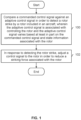
- the technique includes comparing a commanded control signal against an adaptive control signal in order to detect a rotor strike by a rotor included in an aircraft, where the adaptive control signal is associated with controlling the rotor and the adaptive control signal varies based at least in part on the commanded control signal and state information associated with the rotor; in response to detecting the rotor strike, a control signal to the rotor is adjusted in order to reduce a striking force associated with the rotor.
- Figure 1 is a flowchart illustrating an embodiment of a process to detect a rotor strike and perform an adjustment to reduce a striking force in response to a detected rotor strike.
- the process is performed by an aircraft (e.g., a multicopter) where the rotors have no shield or guard to prevent the rotors from striking anything.
- aircraft are not taking off and landing at airports and therefore space around the aircraft may be less controlled compared to airports during takeoff and landing.
- the aircraft is a single-seat, recreational multicopter and the owner takes off and lands from his/her backyard (e.g., where the multicopter may strike a person, a pet, a tree, etc.).
- a commanded control signal is compared against an adaptive control signal in order to detect a rotor strike by a rotor included in an aircraft, wherein the adaptive control signal is associated with controlling the rotor and the adaptive control signal varies based at least in part on the commanded control signal and state information associated with the rotor.
- the commanded control signal is based on a pilot's instructions or commands (e.g., which are received via one or more hand controls, such as a joystick, a thumbwheel, etc.) and/or a flight controller (e.g., the pilot is not touching the joystick and the flight computer performs small adjustments to keep the multicopter hover in air in the same position).
- the aircraft has an automated flight controller (e.g., in an unmanned aircraft with autonomous flight capabilities) and the commanded control signal comes from the automated flight controller.
- the commanded control signal conveys or otherwise indicates a desired rotations per minute (RPMs) or a desired torque (e.g., associated with a particular rotor in the case of a multicopter).
- RPMs rotations per minute
- desired torque e.g., associated with a particular rotor in the case of a multicopter
- a rotor strike is detected or declared at step 100 when the adaptive control signal and the commanded control signal do not indicate the same or similar thing (e.g., similar RPMs or similar torques). For example, suppose that the pilot is not holding the joystick and so the flight controller only makes small changes to the commanded control signal so that the aircraft hovers in air at constant position. If, during this period, a very large spike or increase (e.g., in torque) is observed in the adaptive control signal, this would be flagged as a rotor strike (at least in this example) because there was no corresponding indicator in the commanded control signal that an increase (e.g., in torque) was requested by the pilot and/or the flight controller. Presumably, the rotor has hit something and this resistance was observed by the control system and/or feedback loop, causing the adaptive control signal to increase.
- the adaptive control signal e.g., similar RPMs or similar torques.
- a control signal to the rotor is adjusted in order to reduce a striking force associated with the rotor.
- the control signal which is adjusted is the adaptive control signal.
- the commanded control signal may be the control signal which is adjusted at step 102.
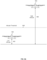
- FIG. 2A is a diagram illustrating a top view of a multicopter embodiment with unshielded rotors.
- multicopter 200 is a single seat aircraft with 10 rotors where the rotors have no guard or shield (e.g., for cost and/or weight reasons) to prevent the rotors from coming into contact with something, either while the multicopter is on the ground or in the air.
- the rotors are mounted to the multicopter at fixed positions or angles. To maneuver, the various rotors are rotated independently of one another at different speeds.
- the rotors are all slightly angled (i.e., they do not rotate in a level horizontal plane) to make the multicopter more maneuverable.
- each of the 10 rotors in this example has its own set of hardware and/or electrical components which monitor the corresponding rotor for a rotor strike.
- each set of electronics independently performs the process of Figure 1 on its respective rotor. That way, even if one set of electronics (e.g., associated with one rotor) fails, a rotor strike can still be detected for another rotor and the striking force for that rotor can be reduced.
- the adaptive control signal (not shown) includes a plurality of phase-shifted sinusoidal signals.
- the following figures describe an example of this.
- the phase-shifted sinusoidal signals (300) are generated in this example by a motor controller (302) which includes a rotor strike detector (308) and drive and control block (309).
- the motor controller (and more specifically, the drive and control block) inputs a commanded control signal (310), state information from sensors (304), and a strike indication signal from rotor strike detector 308 in order to generate the three phase-shifted sinusoidal signals (300).
- the adaptive control signals may be set to values which will "back off" the rotor's striking force (e.g., either by actively “braking” the rotor, or by exerting no new or additional torque so that the rotor eventually comes to a stop).
- the phase-shifted sinusoidal signals (300) are passed to rotor 306 and control the rotation of the rotor (306).
- the rotor (306) attempts to rotate faster and/or with more torque.
- the phase-shifted sinusoidal signals (or, more generally, the adaptive control signal) can indicate directionality of rotation.
- one direction of rotation may be associated with normal operation (e.g., where in this direction the rotors provide the necessary lift for the aircraft to fly) and the other direction of rotation may be used as a brake (e.g., in the event a rotor strike is detected and the system is trying to bring the rotor to a stop as fast as possible).
- the rotor (306) causes changes to the state of the rotor and these changes are measured by sensors (304) which output state information.
- the state information from the sensors may relate to a measured RPM of the rotor, a measured torque of the rotor, etc.
- the sensors may include GPS, gyroscopes, accelerometers, etc. For simplicity, only a single rotor is shown here but as Figure 2A and Figure 2B show, an aircraft may include more than one rotor and rotor strike detector and/or rotor force mitigation components may be duplicated for redundancy and/or to avoid a single point of failure.
- rotor strike detector (308) may be implemented as a field-programmable gate array (FPGA), which would tend to permit more complex and/or powerful rotor strike detection processing operations.
- the rotor strike detector may be implemented using a microprocessor (e.g., where the microprocessor is shared between a rotor strike detection process and other flight-related processes where less complex and/or less powerful rotor strike detection processing operations are supported).
- the motor controller (302) will adjust the phase-shifted sinusoidal signals as or if needed.
- the following figures show some examples of this.
- the commanded control signal (320) increases to a second, higher level (L1).
- the magnitudes and frequencies of the A signal (322), B signal (324), and C signal (326) increase so that they match the level of the commanded control signal (320) at L1. It is clear that in this example, the observed change in the magnitude and frequency of the A signal (322), B signal (324), and C signal (326) is due to the commanded control signal and not (as an example) to counter an external force.
- a scenario like the one shown in Figure 3B shows an example where a rotor strike would not be declared (e.g., because the change in the phase-shifted sinusoidal signals corresponds and/or is corroborated by the change in the commanded control signal).
- Figure 3C shows an example of something that would be flagged as a rotor strike (e.g., because the change in the frequency and/or amplitude of the phase-shifted sinusoidal signals is not due to or in response to some change in the commanded control signal).
- Figure 4 is a diagram illustrating an embodiment of an adaptive measurement threshold which is based on a commanded control signal.
- the value of the measurement threshold is based upon the value of the commanded control signal.
- the exemplary measurement threshold shown here is an adaptive measurement threshold as opposed to a fixed measurement threshold.
- a fixed measurement threshold is used (e.g., where the measurement threshold does not vary or change with the commanded control signal).
- the measurement threshold takes into account the value of the commanded control signal.
- an increase in a (phase-shifted) sinusoidal signal could come from either resistance or the commanded control signal.
- the detection threshold is set to a value which differentiates between normal and/or acceptable amounts of resistance which are relatively small versus large amounts of resistance which are probably indicative of a rotor strike. For example, it would be desirable to differentiate between changes in the adaptive control signal due to noise versus changes in the adaptive control signal due to a rotor strike (e.g., where the rotor at least temporarily slows down and/or is impeded).
- rotor strike detector 308 monitors the commanded control signal (310) in real-time and updates an internal measurement threshold in real-time. This measurement threshold is then used to detect a rotor strike as described above. In some embodiments, rotor strike detector 308 uses a lookup table to map the value of the commanded control signal to a corresponding measurement threshold.
- a measurement threshold is merely one example of how a rotor strike may be detected.
- some deviation from a (e.g., sinusoidal) reference signal e.g., which varies depending upon the commanded control signal
- a reference signal e.g., which varies depending upon the commanded control signal
- Figure 5 is a diagram illustrating an embodiment of an adaptive sinusoidal reference signal which is based on a commanded control signal.
- the magnitude of the (sinusoidal) reference signal is selected based on the level or value of the commanded control signal.
- a sinusoidal reference signal with a lower magnitude (500) is selected.
- a sinusoidal reference signal with higher magnitude (510) is selected.
- the commanded control signal may be monitored and the magnitude of the sinusoidal reference signal may be adjusted in response to any changes in the commanded control signal and/or a lookup table may be used to map the commanded control signal to a magnitude to use for the reference signal.
- using a (e.g., sinusoidal) reference signal is faster at detecting a rotor strike than using a measurement threshold in combination with a detection threshold.
- a non-sinusoidal reference signal is used.
- a sawtooth reference signal may be used where the signal is made of various lines for different segments.
- a reference signal is determined based at least in part on the commanded control signal.
- measurement thresholds 400 and 410 from Figure 4 are examples of a reference signal where the value of the measurement threshold varies depending upon the RPM (or, alternatively, torque) value indicated by the commanded control signal.
- sinusoidal reference signals 500 and 510 show another example of a reference signal which is determined at step 600.
- the detection threshold may be used to differentiate between relatively low and/or typical amounts of deviation (e.g., due to relatively low and/or acceptable amounts of resistance, for example, due to noise or small errors) versus relatively high and/or atypical amounts of deviation (e.g., due to a rotor strike).
- relatively low and/or typical amounts of deviation e.g., due to relatively low and/or acceptable amounts of resistance, for example, due to noise or small errors
- relatively high and/or atypical amounts of deviation e.g., due to a rotor strike.
- a control signal to the rotor is adjusted in order to reduce a striking force associated with the rotor.
- Figure 7A is a diagram illustrating an embodiment of electrical connectors and pull-down resistors which are used to adjust a control signal to the rotor in order to reduce a striking force.
- motor controller 700 inputs a commanded control signal (not shown) and outputs an adaptive control signal in the form of three phase-shifted sinusoidal signals (702).
- phase-shifted sinusoidal signals are passed to electrical connectors 704.
- the electrical connectors pass what is observed at the input (i.e., phase-shifted sinusoidal signals 702) through to the output (i.e., rotor inputs 706).
- the rotor (708) would receive and be controlled by the phase-shifted sinusoidal signals (702).
- the electrical connectors will (e.g., at least electrically) disconnect the phase shifted sinusoidal signals (702) from the rotor inputs (706) so that those signals are no longer driven.
- the pull-down resistors (710) will pull the rotor inputs (706) to ground. Pull-up resistors are similar to pull-down resistors except they are connected to power as opposed to ground and in some embodiments a pull-up resistor is used to stop a rotor in a manner similar to that shown here.
- the value set by the pull-down resistors at the rotor input corresponds to cithcr a neutral value (e.g., where no braking force is applied to the rotor) or a value which causes a braking force to be applied to the rotor.
- the electrical connectors (704) are reversible connectors so that (if desired) the phase-shifted sinusoidal inputs (702) can again be passed through to the rotor inputs (706).
- a switch which can be opened or closed
- the electrical connectors may comprise irreversible connectors, such as a fuse which would need to be replaced once it is blown.
- the exemplary system is attractive for a number of reasons. First, it is relatively inexpensive and lightweight, both of which are attractive in low-cost, (ultra)lightweight aircraft applications. It is also simple to implement. Again, for aircraft applications, simplicity is desirable because it is less likely to fail. Lastly, the system is relatively fast. Switching the electrical connectors 704 is relatively fast, so the aircraft can respond quickly once a rotor strike is detected (which is desirable in case a rotor is striking a person).
- the following figure shows another embodiment, where existing components in the motor controller are used to reduce a striking force when a rotor strike is detected.
- Figure 7B is a diagram illustrating an embodiment of built-in switches in a switched converter which are used to adjust a control signal to the rotor in order to reduce a striking force.
- the motor controller (720) includes a switched converter.
- a switched converter is a type of circuit which is used to convert one voltage (e.g., 10 V) into another voltage (e.g., 5 V) using switches.
- the exemplary switched controller actually has a total of three pairs of switches (e.g., each of which generates a corresponding phase-shifted, sinusoidal signal) but to preserve the readability of the figure, only a single pair of switches is shown here.
- the switches are opened and closed in a specific pattern.
- power switch 724 which connects the output signal (i.e., the relevant one of the adaptive control signals) to the 10 V power supply, is closed for some time t while ground switch 726 (which connects the output signal to ground) is open. With the switches in this position, the output signal is connected to the 10 V power supply and not ground so that the output signal is at 10 V for a duration of t.
- the switches are reversed for the same amount of time t: the power switch (724) is opened so that the output is electrically disconnected from the 10 V power supply, and the ground switch (726) is closed so that the output signal is electrically connected to ground.
- The causes the output signal to be 0 V for a duration of t.
- phase-shifted, sinusoidal signals (722) produced are then passed to the rotor, where the amplitude and phase control the rotor (e.g., the torque and rotational speed, respectively).
- both the power switch (724) and ground switch (726) are opened so that the output signal (i.e., one of the phase-shifted, sinusoidal signals) is connected to neither power nor ground so that it is floating). This floating value would cause the rotor to gradually come to a stop (e.g., with inertia causing the rotor to continue rotating, at least at first). Although the rotor is still spinning (at least at first), the striking force is reduced and there is no sudden generation of heat.
- a benefit to using built-in switches in a switched converter is that it does not require new or additional parts since the motor controller already includes a switched converter.
- the electrical connectors (704) and pull-down resistors (710) in Figure 7A may be relatively small, cheap, and/or lightweight, they are still new or additional parts which were not originally in the design.
- Figure 8A is a flowchart illustrating an embodiment of a process to adjust a control signal to the rotor in order to reduce a striking force using a pull resistor.
- the example process shown here is used at step 102 in Figure 1 .
- an electrical connector is used to electrically disconnect the adaptive control signal from a rotor input signal. See, for example, electrical connectors 704 in Figure 7A which use the rotor strike detected signal as the control or select signal.
- the adaptive control signal comprises three phase-shifted sinusoidal signals but, naturally, in some other embodiments, the adaptive control signal may comprise something else.
- an electrical connector may be a switch, a fuse, etc.
- a pull resistor is used to set the rotor input signal to a known value associated with reducing the striking force associated with the rotor. See, for example, pull-down resistors 710 in Figure 7A . If the electrical connectors (704) electrically disconnect the phase-shifted sinusoidal signals (702) from the rotor inputs (706), then the pull-down resistors will bring the rotor inputs (706) to a known value, specifically zero or ground.
- a pull resistor (e.g., referred to in step 802) may in some other embodiments be a pull-up resistor connected to power.
- what constitutes an appropriate response to a rotor strike being detected may depend upon the altitude of the aircraft when a rotor strike is detected.
- the following figures show an example of this, where an aircraft's altitude is taken into consideration.
- Figure 8B is a flowchart illustrating an embodiment of processes to adjust a control signal to the rotor in order to reduce a striking force using built-in switches in a switched converter.
- one of the example processes shown here is used at step 102 in Figure 1 .
- a power switch in a switched converter is opened, wherein the power switch is connected to a power supply at one end and the adaptive control signal at the other end such that opening the power switch electrically disconnects the adaptive control signal from the power supply.
- motor controller 720 in Figure 7B includes a switched controller with three pairs of switches (not all of which are shown). All of the power switches (724) would be opened so that adaptive control signals (722) are not connected to the power supply.
- ground switch e.g., ground switch 726 in Figure 7B
- the ground switch can either be open (e.g., so that the adaptive control signal is floating) or closed (e.g., so that the adaptive control signal is connected to ground) as described above.
- a ground switch in the switched converter is closed, wherein the ground switch is connected to ground at one end and the adaptive control signal at the other end such that closing the power switch electrically connects the adaptive control signal to ground.
- the ground switch is connected to ground at one end and the adaptive control signal at the other end such that closing the power switch electrically connects the adaptive control signal to ground.
- all of the ground switches (726) would be closed. This would cause all of the adaptive control signals (722) to be low (i.e., at the ground value, which would bring rotor 728 to a sudden and/or braking halt).
- a ground switch in the switched converter is opened, wherein the ground switch is connected to ground at one end and the adaptive control signal at the other end such that opening the power switch electrically disconnects the adaptive control signal from ground.
- the ground switch is connected to ground at one end and the adaptive control signal at the other end such that opening the power switch electrically disconnects the adaptive control signal from ground.
- all of the ground switches (726) would be opened. This would cause all of the adaptive control signals (722) to be floating (e.g., which would bring rotor 728 to a gradual stop).
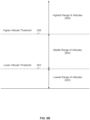
- the aircraft's altitude at that time is obtained, for example, using GPS or a downward-facing sensor such as radar, sonar, or lidar (e.g., which is not dependent upon having a good line-of-sight and/or communication channel to a GPS satellite).
- the obtained altitude is compared against altitude threshold 908. If the aircraft's altitude when the rotor strike is detected is below the altitude threshold (908), the rotor's striking force is reduced in a semi-permanent manner, for example, at least until the rotor and/or some associated components or electronics are reset or otherwise replaced.
- multiple altitude thresholds are used.
- the following figure shows an example of this.
- middle range of altitudes 924 i.e., between the lower altitude threshold (922) and higher altitude threshold (926)
- the multicopter is at a height or altitude where it is unlikely to strike a person.
- the aircraft has a ballistic recovery system (i.e., a parachute system which uses a rocket or other ballistic system to help the parachute inflate)
- the aircraft is too low to the ground for the ballistic recovery system to sufficiently slow down the aircraft.
- the control signal to the rotor is at least temporarily adjusted in order to reduce the striking force associated with the rotor.
- the affected rotor may be permitted (e.g., under certain conditions, after a certain amount of time, if so instructed by a pilot, etc.) to do a flying restart (e.g., without landing and/or without resetting or replacing something). As described above, it may be safer to let the rotor restart at high altitudes in order to prevent or otherwise mitigate a hard or crash landing.
- an altitude associated with the aircraft is obtained.
- the altitude is compared against an altitude threshold.
- the control signal to the rotor is at least temporarily adjusted in order to reduce the striking force associated with the rotor, wherein the rotor is permitted to restart in response to a pilot restart instruction without a reset prior to the pilot restart instruction or a part replacement prior to the pilot restart instruction.
- a pilot control any flying restart because the pilot can make a visual inspection and confirm there is nothing which would be hit by the affected rotor if that rotor were restarted.
- control signal to the rotor is adjusted in order to reduce the striking force associated with the rotor, at least until one or more of the following occurs: a reset or a part replacement.
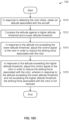
- Figure 10C is a flowchart illustrating an embodiment of a process to adjust the control signal to the rotor in order to reduce the striking force associated with the rotor using two altitude thresholds when there is a parachute system.
- the process of Figure 10C is used at step 102 in Figure 1 .
- an altitude associated with the aircraft is obtained.
- the altitude is compared against a higher altitude threshold and a lower altitude threshold.
- the aircraft may be able to crash safely and includes altitudes where the aircraft may strike people.
- the higher altitude threshold may be associated with a cutoff altitude above which a (e.g., ballistic) recovery system is able to sufficiently slow an aircraft down for a safe landing (and below which, the recovery system would not have enough time to deploy and slow the aircraft down sufficiently).
- the control signal to the rotor is adjusted in order to reduce the striking force associated with the rotor. See, for example, the description of how the system responds in the lowest range of altitudes (920) in Figure 9B .
- the control signal to the rotor is adjusted in order to reduce the striking force associated with the rotor, wherein in response to the altitude exceeding the lower altitude threshold and not exceeding the higher altitude threshold, the striking force associated with the rotor is not reduced. See, for example, the description for how the exemplary aircraft in Figure 9B responds to a rotor strike being detected in the highest range of altitudes (928) and the middle range of altitudes (924).
- the lowest altitude threshold e.g., for leading rotors versus non-leading rotors.
- rotors in the lowest altitude threshold are stopped immediately if a rotor strike is detected, whereas rotors in the highest altitude threshold are stopped gradually if a rotor strike is detected (e.g., where both approaches would still reduce the striking force of the rotor).
Landscapes
- Engineering & Computer Science (AREA)
- Aviation & Aerospace Engineering (AREA)
- Mechanical Engineering (AREA)
- Control Of Electric Motors In General (AREA)
- Regulating Braking Force (AREA)
- Control Of Turbines (AREA)
Claims (7)
- Verfahren, umfassend:Erfassen einer Rotorkollision eines mit einem Luftfahrzeugrotor kollidierenden Gegenstands, wobei das Erfassen das Vergleichen (100) eines befohlenen Steuersignals mit einem adaptiven Steuersignal, um die Rotorkollision durch den in einem Luftfahrzeug enthaltenen Luftfahrzeugrotor zu erfassen, umfasst,wobei das adaptive Steuersignal mit dem Steuern des Luftfahrzeugrotors (306; 708) assoziiert ist und sich das adaptive Steuersignal basierend mindestens zum Teil auf dem befohlenen Steuersignal und mit dem Luftfahrzeugrotor assoziierten Zustandsinformationen ändert; undals Reaktion auf das Erfassen der Rotorkollision, Anpassen (102) eines von dem befohlenen Steuersignal oder dem adaptiven Steuersignal an den Luftfahrzeugrotor, um eine mit dem Luftfahrzeugrotor assoziierte Kollisionskraft zu verringern; wobei das Vergleichen des befohlenen Steuersignals mit dem adaptiven Steuersignal, um die Rotorkollision zu erfassen, Folgendes umfasst:Bestimmen eines Referenzsignals basierend mindestens zum Teil auf dem befohlenen Steuersignal;Bestimmen (602) eines Grads, zu dem das adaptive Steuersignal, das ein Sinussignal umfasst, von dem Referenzsignal abweicht;Vergleichen des Grads mit einer Erfassungsschwelle; undals Reaktion darauf, das der Grad die Erfassungsschwelle überschreitet, Erklären, dass die Rotorkollision erfasst wurde;dadurch gekennzeichnet, dass:
das Anpassen (102) des Steuersignals an den Luftfahrzeugrotor (306; 708), um die Kollisionskraft zu verringern, Folgendes umfasst:als Reaktion auf das Erfassen der Rotorkollision, Verwenden (800) eines elektrischen Verbinders (704), um das adaptive Steuersignal von einem Rotoreingangssignal elektrisch zu trennen; undals Reaktion auf das elektrische Trennen (802) des adaptiven Steuersignals von dem Rotoreingangssignal, Verwenden eines Pull-Widerstands (710), um das Rotoreingangssignal auf einen bekannten Wert einzustellen, der mit dem Verringern der mit dem Luftfahrzeugrotor (708) assoziierten Kollisionskraft assoziiert ist. - Verfahren nach Anspruch 1, wobei das Referenzsignal eines der Folgenden umfasst: eine Messschwelle; und ein Referenzsinussignal.
- Verfahren nach Anspruch 1, wobei das Anpassen (102) des Steuersignals an den Luftfahrzeugrotor (306; 708), um die Kollisionskraft zu verringern, Folgendes umfasst:als Reaktion auf das Erfassen der Rotorkollision, Erhalten (1000) einer mit dem Luftfahrzeug (900, 904) assoziierten Höhe;Vergleichen (1002) der Höhe mit einer Höhenschwelle (908);als Reaktion darauf, dass die Höhe die Höhenschwelle überschreitet, mindestens vorübergehendes Anpassen (1004) des Steuersignals an den Luftfahrzeugrotor, um die mit dem Luftfahrzeugrotor assoziierte Kollisionskraft zu verringern; undals Reaktion darauf, dass die Höhe die Höhenschwelle nicht überschreitet, Anpassen (1006) des Steuersignals an den Luftfahrzeugrotor, um die mit dem Luftfahrzeugrotor assoziierte Kollisionskraft zu verringern, mindestens bis eines der Folgenden stattfindet: ein Zurücksetzen oder ein Teilewechsel.
- Verfahren nach Anspruch 1, wobei das Anpassen (102) des Steuersignals an den Luftfahrzeugrotor (306; 708), um die Kollisionskraft zu verringern, Folgendes umfasst:als Reaktion auf das Erfassen der Rotorkollision, Erhalten (1000) einer mit dem Luftfahrzeug (900, 904) assoziierten Höhe;Vergleichen (1002) der Höhe mit einer Höhenschwelle (908);als Reaktion darauf, dass die Höhe die Höhenschwelle überschreitet, mindestens vorübergehendes Anpassen (1004) des Steuersignals an den Luftfahrzeugrotor, um die mit dem Luftfahrzeugrotor assoziierte Kollisionskraft zu verringern, wobei dem Luftfahrzeugrotor ermöglicht wird, als Reaktion auf eine Wiederanlaufanweisung des Piloten ohne ein Zurücksetzen vor der Wiederanlaufanweisung des Piloten oder einen Teilewechsel vor der Wiederanlaufanweisung des Piloten wiederanzulaufen; undals Reaktion darauf, dass die Höhe die Höhenschwelle nicht überschreitet, Anpassen (1006) des Steuersignals an den Luftfahrzeugrotor, um die mit dem Luftfahrzeugrotor assoziierte Kollisionskraft zu verringern, mindestens bis eines der Folgenden stattfindet: ein Zurücksetzen oder ein Teilewechsel.
- Verfahren nach Anspruch 1, wobei:das Luftfahrzeug (900, 904) ein Fallschirmsystem umfasst; unddas Anpassen (102) des Steuersignals an den Luftfahrzeugrotor (306; 708), um die Kollisionskraft zu verringern, Folgendes umfasst:als Reaktion auf das Erfassen der Rotorkollision, Erhalten (1000) einer mit dem Luftfahrzeug assoziierten Höhe;Vergleichen der Höhe mit einer höheren Höhenschwelle (926) und einer niedrigeren Höhenschwelle (922);als Reaktion darauf, dass die Höhe die niedrigere Höhenschwelle nicht überschreitet, Anpassen des Steuersignals an den Luftfahrzeugrotor, um die mit dem Luftfahrzeugrotor assoziierte Kollisionskraft zu verringern; undals Reaktion darauf, dass die Höhe die höhere Höhenschwelle überschreitet, Anpassen des Steuersignals an den Luftfahrzeugrotor, um die mit dem Luftfahrzeugrotor assoziierte Kollisionskraft zu verringern,wobei als Reaktion darauf, dass die Höhe die niedrigere Höhenschwelle überschreitet und die höhere Höhenschwelle nicht überschreitet, die mit dem Luftfahrzeugrotor assoziierte Kollisionskraft nicht verringert wird.
- System, umfassend:einen elektrischen Verbinder;einen Pull-Widerstand;einen Prozessor; undeinen mit dem Prozessor gekoppelten Speicher, wobei der Speicher dazu konfiguriert ist, dem Prozessor Anweisungen bereitzustellen, die, wenn sie ausgeführt werden, den Prozessor veranlassen, das Verfahren nach einem der Ansprüche 1 bis 5 durchzuführen.
- Computerprogrammprodukt, wobei das Computerprogrammprodukt in einem nicht-transitorischen computerlesbaren Speichermedium verkörpert ist und Computeranweisungen umfasst, die, wenn sie von dem System nach Anspruch 6 ausgeführt werden, die Verfahrensschritte nach einem der Ansprüche 1 bis 5, durchführen.
Priority Applications (1)
| Application Number | Priority Date | Filing Date | Title |
|---|---|---|---|
| EP25152876.6A EP4516681A3 (de) | 2017-12-07 | 2018-09-27 | Rotorschlagerkennung und kraftreduzierung |
Applications Claiming Priority (3)
| Application Number | Priority Date | Filing Date | Title |
|---|---|---|---|
| US201762595963P | 2017-12-07 | 2017-12-07 | |
| US15/877,047 US10246183B1 (en) | 2017-12-07 | 2018-01-22 | Propeller impact detection and force reduction |
| PCT/US2018/053165 WO2019112681A1 (en) | 2017-12-07 | 2018-09-27 | Propeller impact detection and force reduction |
Related Child Applications (2)
| Application Number | Title | Priority Date | Filing Date |
|---|---|---|---|
| EP25152876.6A Division EP4516681A3 (de) | 2017-12-07 | 2018-09-27 | Rotorschlagerkennung und kraftreduzierung |
| EP25152876.6A Division-Into EP4516681A3 (de) | 2017-12-07 | 2018-09-27 | Rotorschlagerkennung und kraftreduzierung |
Publications (3)
| Publication Number | Publication Date |
|---|---|
| EP3720770A1 EP3720770A1 (de) | 2020-10-14 |
| EP3720770A4 EP3720770A4 (de) | 2021-11-10 |
| EP3720770B1 true EP3720770B1 (de) | 2025-03-12 |
Family
ID=65898336
Family Applications (2)
| Application Number | Title | Priority Date | Filing Date |
|---|---|---|---|
| EP25152876.6A Pending EP4516681A3 (de) | 2017-12-07 | 2018-09-27 | Rotorschlagerkennung und kraftreduzierung |
| EP18885161.2A Active EP3720770B1 (de) | 2017-12-07 | 2018-09-27 | Rotorschlag erkennung und kraftreduzierung |
Family Applications Before (1)
| Application Number | Title | Priority Date | Filing Date |
|---|---|---|---|
| EP25152876.6A Pending EP4516681A3 (de) | 2017-12-07 | 2018-09-27 | Rotorschlagerkennung und kraftreduzierung |
Country Status (5)
| Country | Link |
|---|---|
| US (7) | US10246183B1 (de) |
| EP (2) | EP4516681A3 (de) |
| CN (1) | CN111278735B (de) |
| NZ (1) | NZ763334A (de) |
| WO (1) | WO2019112681A1 (de) |
Families Citing this family (6)
| Publication number | Priority date | Publication date | Assignee | Title |
|---|---|---|---|---|
| US11353566B2 (en) | 2018-04-26 | 2022-06-07 | Navico Holding As | Sonar transducer having a gyroscope |
| US11221403B2 (en) * | 2018-05-21 | 2022-01-11 | Navico Holding As | Impact detection devices and methods |
| US11851162B1 (en) * | 2020-01-27 | 2023-12-26 | Snap Inc. | Unmanned aerial vehicle with capacitive sensor propeller stoppage |
| US11447265B1 (en) | 2021-09-14 | 2022-09-20 | Beta Air, Llc | System and method for impact detection capabilities |
| US12119465B2 (en) * | 2022-11-14 | 2024-10-15 | Archer Aviation Inc. | Heat exchanger assemblies and cooling systems for evtol aircraft |
| EP4506244A1 (de) * | 2023-08-09 | 2025-02-12 | Ratier-Figeac SAS | Schutzsystem |
Family Cites Families (18)
| Publication number | Priority date | Publication date | Assignee | Title |
|---|---|---|---|---|
| US6493689B2 (en) | 2000-12-29 | 2002-12-10 | General Dynamics Advanced Technology Systems, Inc. | Neural net controller for noise and vibration reduction |
| EP2594912A1 (de) * | 2011-11-21 | 2013-05-22 | Eurocopter Deutschland GmbH | Detektionssystem zur Detektion von Schäden an rotierenden Komponenten eines Flugzeugs und Verfahren zum Betrieb solch eines Detektionssystems |
| EP2610637B1 (de) * | 2011-12-28 | 2015-10-14 | AIRBUS HELICOPTERS DEUTSCHLAND GmbH | Annäherungswarnsystem für Hubschrauber |
| FR2986269B1 (fr) | 2012-01-30 | 2015-08-07 | Snecma | Systeme de detection d'un impact sur une roue aubagee de moteur d'aeronef |
| EP2817219B1 (de) | 2012-02-22 | 2020-06-03 | Volocopter GmbH | Fluggerät |
| FR2988444B1 (fr) * | 2012-03-20 | 2016-01-15 | Snecma | Detection d'un impact d'objet etranger a l'entree d'un moteur d'aeronef |
| CN108516082B (zh) * | 2013-06-09 | 2021-06-18 | 瑞士苏黎世联邦理工学院 | 遭遇影响效应器的故障的多旋翼器的受控飞行 |
| WO2015127630A1 (en) * | 2014-02-27 | 2015-09-03 | SZ DJI Technology Co., Ltd. | Impact protection apparatus |
| US10780988B2 (en) * | 2014-08-11 | 2020-09-22 | Amazon Technologies, Inc. | Propeller safety for automated aerial vehicles |
| EP2990332A1 (de) * | 2014-08-19 | 2016-03-02 | Tau Emerald Rotors Inc. | Steuerung von drehflügelflugzeugen |
| NL2014310B1 (en) * | 2015-02-18 | 2016-10-13 | Monkeywings Ip B V | Inverted Drone. |
| EP3069990B1 (de) * | 2015-03-20 | 2017-01-11 | AIRBUS HELICOPTERS DEUTSCHLAND GmbH | Vorrichtung zur erzeugung von künstlicher krafterfassung für ein fahrzeugsteuerungssystem eines fahrzeugs, insbesondere eines flugzeugs |
| US20160375982A1 (en) | 2015-06-25 | 2016-12-29 | WILLIAM McKENZIE RIFENBURGH | System and methods associated with a rideable multicopter |
| US9828095B1 (en) | 2015-12-11 | 2017-11-28 | Amazon Technologies, Inc. | Motor deflection monitoring for unmanned aerial vehicles |
| US10399666B2 (en) | 2016-03-23 | 2019-09-03 | Amazon Technologies, Inc. | Aerial vehicle propulsion mechanism with coaxially aligned and independently rotatable propellers |
| US10059447B2 (en) * | 2016-04-11 | 2018-08-28 | ZEROTECH (Chongqing) Intelligence Technology Co., Ltd. | Method an apparatus for controlling unmanned aerial vehicle |
| CN105843241A (zh) * | 2016-04-11 | 2016-08-10 | 零度智控(北京)智能科技有限公司 | 无人机、无人机起飞控制方法及装置 |
| CN107291095B (zh) * | 2016-04-11 | 2021-06-18 | 河北雄安远度科技有限公司 | 无人机起飞控制方法、装置、系统以及无人机 |
-
2018
- 2018-01-22 US US15/877,047 patent/US10246183B1/en active Active
- 2018-09-27 EP EP25152876.6A patent/EP4516681A3/de active Pending
- 2018-09-27 EP EP18885161.2A patent/EP3720770B1/de active Active
- 2018-09-27 CN CN201880072063.4A patent/CN111278735B/zh active Active
- 2018-09-27 NZ NZ763334A patent/NZ763334A/en unknown
- 2018-09-27 WO PCT/US2018/053165 patent/WO2019112681A1/en not_active Ceased
-
2019
- 2019-01-16 US US16/249,645 patent/US10507908B2/en active Active
- 2019-11-04 US US16/673,579 patent/US10814964B2/en active Active
-
2020
- 2020-09-16 US US17/022,990 patent/US11459096B2/en active Active
-
2022
- 2022-08-25 US US17/895,739 patent/US11827343B2/en active Active
-
2023
- 2023-10-19 US US18/381,994 patent/US12157560B2/en active Active
-
2024
- 2024-10-29 US US18/930,815 patent/US20250051005A1/en active Pending
Non-Patent Citations (1)
| Title |
|---|
| JOHNSON DAVID M: "A review of fault management techniques used in safety-critical avionic systems", PROGRESS IN AEROSPACE SCIENCES VOLUME 32, ISSUE 5, OCTOBER 1996, PAGES 415-431, 5 October 1996 (1996-10-05), XP093148145, Retrieved from the Internet <URL:https://www.sciencedirect.com/science/article/pii/0376042196827850> [retrieved on 20240404] * |
Also Published As
| Publication number | Publication date |
|---|---|
| US20210001978A1 (en) | 2021-01-07 |
| US11827343B2 (en) | 2023-11-28 |
| EP4516681A3 (de) | 2025-06-11 |
| US20250051005A1 (en) | 2025-02-13 |
| CN111278735A (zh) | 2020-06-12 |
| WO2019112681A1 (en) | 2019-06-13 |
| EP4516681A2 (de) | 2025-03-05 |
| US10246183B1 (en) | 2019-04-02 |
| US10814964B2 (en) | 2020-10-27 |
| US10507908B2 (en) | 2019-12-17 |
| US12157560B2 (en) | 2024-12-03 |
| US20190176977A1 (en) | 2019-06-13 |
| NZ763334A (en) | 2022-05-27 |
| US20220402599A1 (en) | 2022-12-22 |
| US20240043115A1 (en) | 2024-02-08 |
| EP3720770A1 (de) | 2020-10-14 |
| CN111278735B (zh) | 2023-05-23 |
| EP3720770A4 (de) | 2021-11-10 |
| US11459096B2 (en) | 2022-10-04 |
| US20200062381A1 (en) | 2020-02-27 |
Similar Documents
| Publication | Publication Date | Title |
|---|---|---|
| US12157560B2 (en) | Propeller impact detection and force reduction | |
| US11548631B2 (en) | Multi mode safety system for VTOL aircraft | |
| US9783286B1 (en) | Method and an apparatus for controlling a UAV, and a UAV take-off system | |
| US9632501B1 (en) | Method and apparatus for controlling UAV, and UAV take-off system | |
| US10890463B2 (en) | Takeoff pitch guidance system and method | |
| JP6219002B2 (ja) | 飛行制御装置およびこれを備える無人航空機 | |
| US11194349B2 (en) | Automated autorotation and pilot aiding system | |
| WO2017086234A1 (ja) | 無人航空機 | |
| CN109871034A (zh) | 飞行控制方法、装置及无人飞行器 | |
| US20220380020A1 (en) | Method for assisting the piloting of a rotorcraft comprising at least two engines | |
| JP2009507700A (ja) | 航空機用のエネルギー保護装置 | |
| EP3018054B1 (de) | Verfahren zur Steuerung eines Flugzeugpropellersystems während der Schubumkehr | |
| CA2801632C (en) | Method and device for protecting an aircraft | |
| US9505488B2 (en) | Energy protection method and device for an aircraft | |
| WO2015069228A1 (en) | Tailstrike warning system |
Legal Events
| Date | Code | Title | Description |
|---|---|---|---|
| STAA | Information on the status of an ep patent application or granted ep patent |
Free format text: STATUS: THE INTERNATIONAL PUBLICATION HAS BEEN MADE |
|
| PUAI | Public reference made under article 153(3) epc to a published international application that has entered the european phase |
Free format text: ORIGINAL CODE: 0009012 |
|
| STAA | Information on the status of an ep patent application or granted ep patent |
Free format text: STATUS: REQUEST FOR EXAMINATION WAS MADE |
|
| 17P | Request for examination filed |
Effective date: 20200407 |
|
| AK | Designated contracting states |
Kind code of ref document: A1 Designated state(s): AL AT BE BG CH CY CZ DE DK EE ES FI FR GB GR HR HU IE IS IT LI LT LU LV MC MK MT NL NO PL PT RO RS SE SI SK SM TR |
|
| AX | Request for extension of the european patent |
Extension state: BA ME |
|
| DAV | Request for validation of the european patent (deleted) | ||
| DAX | Request for extension of the european patent (deleted) | ||
| A4 | Supplementary search report drawn up and despatched |
Effective date: 20211011 |
|
| RIC1 | Information provided on ipc code assigned before grant |
Ipc: B64D 45/00 20060101ALI20211005BHEP Ipc: B64C 27/00 20060101ALI20211005BHEP Ipc: B64C 39/02 20060101ALI20211005BHEP Ipc: B64C 29/00 20060101ALI20211005BHEP Ipc: B64C 27/20 20060101ALI20211005BHEP Ipc: B64C 27/08 20060101ALI20211005BHEP Ipc: B64C 11/46 20060101ALI20211005BHEP Ipc: B64D 31/06 20060101AFI20211005BHEP |
|
| STAA | Information on the status of an ep patent application or granted ep patent |
Free format text: STATUS: EXAMINATION IS IN PROGRESS |
|
| 17Q | First examination report despatched |
Effective date: 20230315 |
|
| P01 | Opt-out of the competence of the unified patent court (upc) registered |
Effective date: 20230605 |
|
| GRAP | Despatch of communication of intention to grant a patent |
Free format text: ORIGINAL CODE: EPIDOSNIGR1 |
|
| STAA | Information on the status of an ep patent application or granted ep patent |
Free format text: STATUS: GRANT OF PATENT IS INTENDED |
|
| INTG | Intention to grant announced |
Effective date: 20241008 |
|
| RAP3 | Party data changed (applicant data changed or rights of an application transferred) |
Owner name: KITTY HAWK CORPORATION |
|
| GRAS | Grant fee paid |
Free format text: ORIGINAL CODE: EPIDOSNIGR3 |
|
| GRAA | (expected) grant |
Free format text: ORIGINAL CODE: 0009210 |
|
| STAA | Information on the status of an ep patent application or granted ep patent |
Free format text: STATUS: THE PATENT HAS BEEN GRANTED |
|
| AK | Designated contracting states |
Kind code of ref document: B1 Designated state(s): AL AT BE BG CH CY CZ DE DK EE ES FI FR GB GR HR HU IE IS IT LI LT LU LV MC MK MT NL NO PL PT RO RS SE SI SK SM TR |
|
| REG | Reference to a national code |
Ref country code: GB Ref legal event code: FG4D |
|
| REG | Reference to a national code |
Ref country code: CH Ref legal event code: EP |
|
| REG | Reference to a national code |
Ref country code: DE Ref legal event code: R096 Ref document number: 602018080138 Country of ref document: DE |
|
| REG | Reference to a national code |
Ref country code: IE Ref legal event code: FG4D |
|
| PG25 | Lapsed in a contracting state [announced via postgrant information from national office to epo] |
Ref country code: RS Free format text: LAPSE BECAUSE OF FAILURE TO SUBMIT A TRANSLATION OF THE DESCRIPTION OR TO PAY THE FEE WITHIN THE PRESCRIBED TIME-LIMIT Effective date: 20250612 |
|
| PG25 | Lapsed in a contracting state [announced via postgrant information from national office to epo] |
Ref country code: FI Free format text: LAPSE BECAUSE OF FAILURE TO SUBMIT A TRANSLATION OF THE DESCRIPTION OR TO PAY THE FEE WITHIN THE PRESCRIBED TIME-LIMIT Effective date: 20250312 |
|
| PG25 | Lapsed in a contracting state [announced via postgrant information from national office to epo] |
Ref country code: ES Free format text: LAPSE BECAUSE OF FAILURE TO SUBMIT A TRANSLATION OF THE DESCRIPTION OR TO PAY THE FEE WITHIN THE PRESCRIBED TIME-LIMIT Effective date: 20250312 |
|
| REG | Reference to a national code |
Ref country code: LT Ref legal event code: MG9D |
|
| PG25 | Lapsed in a contracting state [announced via postgrant information from national office to epo] |
Ref country code: NO Free format text: LAPSE BECAUSE OF FAILURE TO SUBMIT A TRANSLATION OF THE DESCRIPTION OR TO PAY THE FEE WITHIN THE PRESCRIBED TIME-LIMIT Effective date: 20250612 |
|
| PG25 | Lapsed in a contracting state [announced via postgrant information from national office to epo] |
Ref country code: HR Free format text: LAPSE BECAUSE OF FAILURE TO SUBMIT A TRANSLATION OF THE DESCRIPTION OR TO PAY THE FEE WITHIN THE PRESCRIBED TIME-LIMIT Effective date: 20250312 |
|
| REG | Reference to a national code |
Ref country code: NL Ref legal event code: MP Effective date: 20250312 |
|
| PG25 | Lapsed in a contracting state [announced via postgrant information from national office to epo] |
Ref country code: LV Free format text: LAPSE BECAUSE OF FAILURE TO SUBMIT A TRANSLATION OF THE DESCRIPTION OR TO PAY THE FEE WITHIN THE PRESCRIBED TIME-LIMIT Effective date: 20250312 |
|
| PG25 | Lapsed in a contracting state [announced via postgrant information from national office to epo] |
Ref country code: GR Free format text: LAPSE BECAUSE OF FAILURE TO SUBMIT A TRANSLATION OF THE DESCRIPTION OR TO PAY THE FEE WITHIN THE PRESCRIBED TIME-LIMIT Effective date: 20250613 Ref country code: BG Free format text: LAPSE BECAUSE OF FAILURE TO SUBMIT A TRANSLATION OF THE DESCRIPTION OR TO PAY THE FEE WITHIN THE PRESCRIBED TIME-LIMIT Effective date: 20250312 |
|
| REG | Reference to a national code |
Ref country code: AT Ref legal event code: MK05 Ref document number: 1774855 Country of ref document: AT Kind code of ref document: T Effective date: 20250312 |
|
| PG25 | Lapsed in a contracting state [announced via postgrant information from national office to epo] |
Ref country code: NL Free format text: LAPSE BECAUSE OF FAILURE TO SUBMIT A TRANSLATION OF THE DESCRIPTION OR TO PAY THE FEE WITHIN THE PRESCRIBED TIME-LIMIT Effective date: 20250312 |
|
| PG25 | Lapsed in a contracting state [announced via postgrant information from national office to epo] |
Ref country code: SE Free format text: LAPSE BECAUSE OF FAILURE TO SUBMIT A TRANSLATION OF THE DESCRIPTION OR TO PAY THE FEE WITHIN THE PRESCRIBED TIME-LIMIT Effective date: 20250312 |
|
| PG25 | Lapsed in a contracting state [announced via postgrant information from national office to epo] |
Ref country code: SM Free format text: LAPSE BECAUSE OF FAILURE TO SUBMIT A TRANSLATION OF THE DESCRIPTION OR TO PAY THE FEE WITHIN THE PRESCRIBED TIME-LIMIT Effective date: 20250312 |
|
| PG25 | Lapsed in a contracting state [announced via postgrant information from national office to epo] |
Ref country code: PT Free format text: LAPSE BECAUSE OF FAILURE TO SUBMIT A TRANSLATION OF THE DESCRIPTION OR TO PAY THE FEE WITHIN THE PRESCRIBED TIME-LIMIT Effective date: 20250714 |
|
| PGFP | Annual fee paid to national office [announced via postgrant information from national office to epo] |
Ref country code: DE Payment date: 20250820 Year of fee payment: 8 |
|
| PG25 | Lapsed in a contracting state [announced via postgrant information from national office to epo] |
Ref country code: PL Free format text: LAPSE BECAUSE OF FAILURE TO SUBMIT A TRANSLATION OF THE DESCRIPTION OR TO PAY THE FEE WITHIN THE PRESCRIBED TIME-LIMIT Effective date: 20250312 Ref country code: IT Free format text: LAPSE BECAUSE OF FAILURE TO SUBMIT A TRANSLATION OF THE DESCRIPTION OR TO PAY THE FEE WITHIN THE PRESCRIBED TIME-LIMIT Effective date: 20250312 |
|
| PGFP | Annual fee paid to national office [announced via postgrant information from national office to epo] |
Ref country code: GB Payment date: 20250820 Year of fee payment: 8 |
|
| PG25 | Lapsed in a contracting state [announced via postgrant information from national office to epo] |
Ref country code: AT Free format text: LAPSE BECAUSE OF FAILURE TO SUBMIT A TRANSLATION OF THE DESCRIPTION OR TO PAY THE FEE WITHIN THE PRESCRIBED TIME-LIMIT Effective date: 20250312 |
|
| PGFP | Annual fee paid to national office [announced via postgrant information from national office to epo] |
Ref country code: FR Payment date: 20250820 Year of fee payment: 8 |
|
| PG25 | Lapsed in a contracting state [announced via postgrant information from national office to epo] |
Ref country code: CZ Free format text: LAPSE BECAUSE OF FAILURE TO SUBMIT A TRANSLATION OF THE DESCRIPTION OR TO PAY THE FEE WITHIN THE PRESCRIBED TIME-LIMIT Effective date: 20250312 Ref country code: EE Free format text: LAPSE BECAUSE OF FAILURE TO SUBMIT A TRANSLATION OF THE DESCRIPTION OR TO PAY THE FEE WITHIN THE PRESCRIBED TIME-LIMIT Effective date: 20250312 |
|
| PG25 | Lapsed in a contracting state [announced via postgrant information from national office to epo] |
Ref country code: RO Free format text: LAPSE BECAUSE OF FAILURE TO SUBMIT A TRANSLATION OF THE DESCRIPTION OR TO PAY THE FEE WITHIN THE PRESCRIBED TIME-LIMIT Effective date: 20250312 |
|
| PG25 | Lapsed in a contracting state [announced via postgrant information from national office to epo] |
Ref country code: SK Free format text: LAPSE BECAUSE OF FAILURE TO SUBMIT A TRANSLATION OF THE DESCRIPTION OR TO PAY THE FEE WITHIN THE PRESCRIBED TIME-LIMIT Effective date: 20250312 |
|
| PG25 | Lapsed in a contracting state [announced via postgrant information from national office to epo] |
Ref country code: IS Free format text: LAPSE BECAUSE OF FAILURE TO SUBMIT A TRANSLATION OF THE DESCRIPTION OR TO PAY THE FEE WITHIN THE PRESCRIBED TIME-LIMIT Effective date: 20250712 |
|
| REG | Reference to a national code |
Ref country code: DE Ref legal event code: R097 Ref document number: 602018080138 Country of ref document: DE |
|
| PG25 | Lapsed in a contracting state [announced via postgrant information from national office to epo] |
Ref country code: DK Free format text: LAPSE BECAUSE OF FAILURE TO SUBMIT A TRANSLATION OF THE DESCRIPTION OR TO PAY THE FEE WITHIN THE PRESCRIBED TIME-LIMIT Effective date: 20250312 |
|
| PLBE | No opposition filed within time limit |
Free format text: ORIGINAL CODE: 0009261 |
|
| STAA | Information on the status of an ep patent application or granted ep patent |
Free format text: STATUS: NO OPPOSITION FILED WITHIN TIME LIMIT |
|
| REG | Reference to a national code |
Ref country code: CH Ref legal event code: L10 Free format text: ST27 STATUS EVENT CODE: U-0-0-L10-L00 (AS PROVIDED BY THE NATIONAL OFFICE) Effective date: 20260121 |
|
| 26N | No opposition filed |
Effective date: 20251215 |