EP3720730B1 - Getriebe für ein kraftfahrzeug, antriebsstrang, sowie verfahren zum betrieb eines getriebes - Google Patents
Getriebe für ein kraftfahrzeug, antriebsstrang, sowie verfahren zum betrieb eines getriebes Download PDFInfo
- Publication number
- EP3720730B1 EP3720730B1 EP18825879.2A EP18825879A EP3720730B1 EP 3720730 B1 EP3720730 B1 EP 3720730B1 EP 18825879 A EP18825879 A EP 18825879A EP 3720730 B1 EP3720730 B1 EP 3720730B1
- Authority
- EP
- European Patent Office
- Prior art keywords
- transmission
- gear
- planetary gear
- input shaft
- forming
- Prior art date
- Legal status (The legal status is an assumption and is not a legal conclusion. Google has not performed a legal analysis and makes no representation as to the accuracy of the status listed.)
- Not-in-force
Links
Images



Classifications
-
- B—PERFORMING OPERATIONS; TRANSPORTING
- B60—VEHICLES IN GENERAL
- B60K—ARRANGEMENT OR MOUNTING OF PROPULSION UNITS OR OF TRANSMISSIONS IN VEHICLES; ARRANGEMENT OR MOUNTING OF PLURAL DIVERSE PRIME-MOVERS IN VEHICLES; AUXILIARY DRIVES FOR VEHICLES; INSTRUMENTATION OR DASHBOARDS FOR VEHICLES; ARRANGEMENTS IN CONNECTION WITH COOLING, AIR INTAKE, GAS EXHAUST OR FUEL SUPPLY OF PROPULSION UNITS IN VEHICLES
- B60K6/00—Arrangement or mounting of plural diverse prime-movers for mutual or common propulsion, e.g. hybrid propulsion systems comprising electric motors and internal combustion engines
- B60K6/20—Arrangement or mounting of plural diverse prime-movers for mutual or common propulsion, e.g. hybrid propulsion systems comprising electric motors and internal combustion engines the prime-movers consisting of electric motors and internal combustion engines, e.g. HEVs
- B60K6/22—Arrangement or mounting of plural diverse prime-movers for mutual or common propulsion, e.g. hybrid propulsion systems comprising electric motors and internal combustion engines the prime-movers consisting of electric motors and internal combustion engines, e.g. HEVs characterised by apparatus, components or means specially adapted for HEVs
- B60K6/38—Arrangement or mounting of plural diverse prime-movers for mutual or common propulsion, e.g. hybrid propulsion systems comprising electric motors and internal combustion engines the prime-movers consisting of electric motors and internal combustion engines, e.g. HEVs characterised by apparatus, components or means specially adapted for HEVs characterised by the driveline clutches
- B60K6/387—Actuated clutches, i.e. clutches engaged or disengaged by electric, hydraulic or mechanical actuating means
-
- B—PERFORMING OPERATIONS; TRANSPORTING
- B60—VEHICLES IN GENERAL
- B60K—ARRANGEMENT OR MOUNTING OF PROPULSION UNITS OR OF TRANSMISSIONS IN VEHICLES; ARRANGEMENT OR MOUNTING OF PLURAL DIVERSE PRIME-MOVERS IN VEHICLES; AUXILIARY DRIVES FOR VEHICLES; INSTRUMENTATION OR DASHBOARDS FOR VEHICLES; ARRANGEMENTS IN CONNECTION WITH COOLING, AIR INTAKE, GAS EXHAUST OR FUEL SUPPLY OF PROPULSION UNITS IN VEHICLES
- B60K6/00—Arrangement or mounting of plural diverse prime-movers for mutual or common propulsion, e.g. hybrid propulsion systems comprising electric motors and internal combustion engines
- B60K6/20—Arrangement or mounting of plural diverse prime-movers for mutual or common propulsion, e.g. hybrid propulsion systems comprising electric motors and internal combustion engines the prime-movers consisting of electric motors and internal combustion engines, e.g. HEVs
- B60K6/22—Arrangement or mounting of plural diverse prime-movers for mutual or common propulsion, e.g. hybrid propulsion systems comprising electric motors and internal combustion engines the prime-movers consisting of electric motors and internal combustion engines, e.g. HEVs characterised by apparatus, components or means specially adapted for HEVs
- B60K6/36—Arrangement or mounting of plural diverse prime-movers for mutual or common propulsion, e.g. hybrid propulsion systems comprising electric motors and internal combustion engines the prime-movers consisting of electric motors and internal combustion engines, e.g. HEVs characterised by apparatus, components or means specially adapted for HEVs characterised by the transmission gearings
- B60K6/365—Arrangement or mounting of plural diverse prime-movers for mutual or common propulsion, e.g. hybrid propulsion systems comprising electric motors and internal combustion engines the prime-movers consisting of electric motors and internal combustion engines, e.g. HEVs characterised by apparatus, components or means specially adapted for HEVs characterised by the transmission gearings with the gears having orbital motion
-
- B—PERFORMING OPERATIONS; TRANSPORTING
- B60—VEHICLES IN GENERAL
- B60K—ARRANGEMENT OR MOUNTING OF PROPULSION UNITS OR OF TRANSMISSIONS IN VEHICLES; ARRANGEMENT OR MOUNTING OF PLURAL DIVERSE PRIME-MOVERS IN VEHICLES; AUXILIARY DRIVES FOR VEHICLES; INSTRUMENTATION OR DASHBOARDS FOR VEHICLES; ARRANGEMENTS IN CONNECTION WITH COOLING, AIR INTAKE, GAS EXHAUST OR FUEL SUPPLY OF PROPULSION UNITS IN VEHICLES
- B60K6/00—Arrangement or mounting of plural diverse prime-movers for mutual or common propulsion, e.g. hybrid propulsion systems comprising electric motors and internal combustion engines
- B60K6/20—Arrangement or mounting of plural diverse prime-movers for mutual or common propulsion, e.g. hybrid propulsion systems comprising electric motors and internal combustion engines the prime-movers consisting of electric motors and internal combustion engines, e.g. HEVs
- B60K6/42—Arrangement or mounting of plural diverse prime-movers for mutual or common propulsion, e.g. hybrid propulsion systems comprising electric motors and internal combustion engines the prime-movers consisting of electric motors and internal combustion engines, e.g. HEVs characterised by the architecture of the hybrid electric vehicle
- B60K6/48—Parallel type
-
- B—PERFORMING OPERATIONS; TRANSPORTING
- B60—VEHICLES IN GENERAL
- B60K—ARRANGEMENT OR MOUNTING OF PROPULSION UNITS OR OF TRANSMISSIONS IN VEHICLES; ARRANGEMENT OR MOUNTING OF PLURAL DIVERSE PRIME-MOVERS IN VEHICLES; AUXILIARY DRIVES FOR VEHICLES; INSTRUMENTATION OR DASHBOARDS FOR VEHICLES; ARRANGEMENTS IN CONNECTION WITH COOLING, AIR INTAKE, GAS EXHAUST OR FUEL SUPPLY OF PROPULSION UNITS IN VEHICLES
- B60K6/00—Arrangement or mounting of plural diverse prime-movers for mutual or common propulsion, e.g. hybrid propulsion systems comprising electric motors and internal combustion engines
- B60K6/20—Arrangement or mounting of plural diverse prime-movers for mutual or common propulsion, e.g. hybrid propulsion systems comprising electric motors and internal combustion engines the prime-movers consisting of electric motors and internal combustion engines, e.g. HEVs
- B60K6/50—Architecture of the driveline characterised by arrangement or kind of transmission units
- B60K6/54—Transmission for changing ratio
- B60K6/547—Transmission for changing ratio the transmission being a stepped gearing
-
- B—PERFORMING OPERATIONS; TRANSPORTING
- B60—VEHICLES IN GENERAL
- B60W—CONJOINT CONTROL OF VEHICLE SUB-UNITS OF DIFFERENT TYPE OR DIFFERENT FUNCTION; CONTROL SYSTEMS SPECIALLY ADAPTED FOR HYBRID VEHICLES; ROAD VEHICLE DRIVE CONTROL SYSTEMS FOR PURPOSES NOT RELATED TO THE CONTROL OF A PARTICULAR SUB-UNIT
- B60W10/00—Conjoint control of vehicle sub-units of different type or different function
- B60W10/04—Conjoint control of vehicle sub-units of different type or different function including control of propulsion units
- B60W10/08—Conjoint control of vehicle sub-units of different type or different function including control of propulsion units including control of electric propulsion units, e.g. motors or generators
-
- B—PERFORMING OPERATIONS; TRANSPORTING
- B60—VEHICLES IN GENERAL
- B60W—CONJOINT CONTROL OF VEHICLE SUB-UNITS OF DIFFERENT TYPE OR DIFFERENT FUNCTION; CONTROL SYSTEMS SPECIALLY ADAPTED FOR HYBRID VEHICLES; ROAD VEHICLE DRIVE CONTROL SYSTEMS FOR PURPOSES NOT RELATED TO THE CONTROL OF A PARTICULAR SUB-UNIT
- B60W10/00—Conjoint control of vehicle sub-units of different type or different function
- B60W10/10—Conjoint control of vehicle sub-units of different type or different function including control of change-speed gearings
- B60W10/11—Stepped gearings
- B60W10/115—Stepped gearings with planetary gears
-
- F—MECHANICAL ENGINEERING; LIGHTING; HEATING; WEAPONS; BLASTING
- F16—ENGINEERING ELEMENTS AND UNITS; GENERAL MEASURES FOR PRODUCING AND MAINTAINING EFFECTIVE FUNCTIONING OF MACHINES OR INSTALLATIONS; THERMAL INSULATION IN GENERAL
- F16H—GEARING
- F16H3/00—Toothed gearings for conveying rotary motion with variable gear ratio or for reversing rotary motion
- F16H3/44—Toothed gearings for conveying rotary motion with variable gear ratio or for reversing rotary motion using gears having orbital motion
- F16H3/62—Gearings having three or more central gears
- F16H3/66—Gearings having three or more central gears composed of a number of gear trains without drive passing from one train to another
-
- B—PERFORMING OPERATIONS; TRANSPORTING
- B60—VEHICLES IN GENERAL
- B60K—ARRANGEMENT OR MOUNTING OF PROPULSION UNITS OR OF TRANSMISSIONS IN VEHICLES; ARRANGEMENT OR MOUNTING OF PLURAL DIVERSE PRIME-MOVERS IN VEHICLES; AUXILIARY DRIVES FOR VEHICLES; INSTRUMENTATION OR DASHBOARDS FOR VEHICLES; ARRANGEMENTS IN CONNECTION WITH COOLING, AIR INTAKE, GAS EXHAUST OR FUEL SUPPLY OF PROPULSION UNITS IN VEHICLES
- B60K6/00—Arrangement or mounting of plural diverse prime-movers for mutual or common propulsion, e.g. hybrid propulsion systems comprising electric motors and internal combustion engines
- B60K6/20—Arrangement or mounting of plural diverse prime-movers for mutual or common propulsion, e.g. hybrid propulsion systems comprising electric motors and internal combustion engines the prime-movers consisting of electric motors and internal combustion engines, e.g. HEVs
- B60K6/22—Arrangement or mounting of plural diverse prime-movers for mutual or common propulsion, e.g. hybrid propulsion systems comprising electric motors and internal combustion engines the prime-movers consisting of electric motors and internal combustion engines, e.g. HEVs characterised by apparatus, components or means specially adapted for HEVs
- B60K6/26—Arrangement or mounting of plural diverse prime-movers for mutual or common propulsion, e.g. hybrid propulsion systems comprising electric motors and internal combustion engines the prime-movers consisting of electric motors and internal combustion engines, e.g. HEVs characterised by apparatus, components or means specially adapted for HEVs characterised by the motors or the generators
- B60K2006/268—Electric drive motor starts the engine, i.e. used as starter motor
-
- B—PERFORMING OPERATIONS; TRANSPORTING
- B60—VEHICLES IN GENERAL
- B60K—ARRANGEMENT OR MOUNTING OF PROPULSION UNITS OR OF TRANSMISSIONS IN VEHICLES; ARRANGEMENT OR MOUNTING OF PLURAL DIVERSE PRIME-MOVERS IN VEHICLES; AUXILIARY DRIVES FOR VEHICLES; INSTRUMENTATION OR DASHBOARDS FOR VEHICLES; ARRANGEMENTS IN CONNECTION WITH COOLING, AIR INTAKE, GAS EXHAUST OR FUEL SUPPLY OF PROPULSION UNITS IN VEHICLES
- B60K6/00—Arrangement or mounting of plural diverse prime-movers for mutual or common propulsion, e.g. hybrid propulsion systems comprising electric motors and internal combustion engines
- B60K6/20—Arrangement or mounting of plural diverse prime-movers for mutual or common propulsion, e.g. hybrid propulsion systems comprising electric motors and internal combustion engines the prime-movers consisting of electric motors and internal combustion engines, e.g. HEVs
- B60K6/22—Arrangement or mounting of plural diverse prime-movers for mutual or common propulsion, e.g. hybrid propulsion systems comprising electric motors and internal combustion engines the prime-movers consisting of electric motors and internal combustion engines, e.g. HEVs characterised by apparatus, components or means specially adapted for HEVs
- B60K6/38—Arrangement or mounting of plural diverse prime-movers for mutual or common propulsion, e.g. hybrid propulsion systems comprising electric motors and internal combustion engines the prime-movers consisting of electric motors and internal combustion engines, e.g. HEVs characterised by apparatus, components or means specially adapted for HEVs characterised by the driveline clutches
- B60K2006/381—Arrangement or mounting of plural diverse prime-movers for mutual or common propulsion, e.g. hybrid propulsion systems comprising electric motors and internal combustion engines the prime-movers consisting of electric motors and internal combustion engines, e.g. HEVs characterised by apparatus, components or means specially adapted for HEVs characterised by the driveline clutches characterized by driveline brakes
-
- B—PERFORMING OPERATIONS; TRANSPORTING
- B60—VEHICLES IN GENERAL
- B60K—ARRANGEMENT OR MOUNTING OF PROPULSION UNITS OR OF TRANSMISSIONS IN VEHICLES; ARRANGEMENT OR MOUNTING OF PLURAL DIVERSE PRIME-MOVERS IN VEHICLES; AUXILIARY DRIVES FOR VEHICLES; INSTRUMENTATION OR DASHBOARDS FOR VEHICLES; ARRANGEMENTS IN CONNECTION WITH COOLING, AIR INTAKE, GAS EXHAUST OR FUEL SUPPLY OF PROPULSION UNITS IN VEHICLES
- B60K6/00—Arrangement or mounting of plural diverse prime-movers for mutual or common propulsion, e.g. hybrid propulsion systems comprising electric motors and internal combustion engines
- B60K6/20—Arrangement or mounting of plural diverse prime-movers for mutual or common propulsion, e.g. hybrid propulsion systems comprising electric motors and internal combustion engines the prime-movers consisting of electric motors and internal combustion engines, e.g. HEVs
- B60K6/42—Arrangement or mounting of plural diverse prime-movers for mutual or common propulsion, e.g. hybrid propulsion systems comprising electric motors and internal combustion engines the prime-movers consisting of electric motors and internal combustion engines, e.g. HEVs characterised by the architecture of the hybrid electric vehicle
- B60K6/48—Parallel type
- B60K2006/4816—Electric machine connected or connectable to gearbox internal shaft
-
- F—MECHANICAL ENGINEERING; LIGHTING; HEATING; WEAPONS; BLASTING
- F16—ENGINEERING ELEMENTS AND UNITS; GENERAL MEASURES FOR PRODUCING AND MAINTAINING EFFECTIVE FUNCTIONING OF MACHINES OR INSTALLATIONS; THERMAL INSULATION IN GENERAL
- F16H—GEARING
- F16H3/00—Toothed gearings for conveying rotary motion with variable gear ratio or for reversing rotary motion
- F16H3/44—Toothed gearings for conveying rotary motion with variable gear ratio or for reversing rotary motion using gears having orbital motion
- F16H2003/442—Toothed gearings for conveying rotary motion with variable gear ratio or for reversing rotary motion using gears having orbital motion comprising two or more sets of orbital gears arranged in a single plane
-
- F—MECHANICAL ENGINEERING; LIGHTING; HEATING; WEAPONS; BLASTING
- F16—ENGINEERING ELEMENTS AND UNITS; GENERAL MEASURES FOR PRODUCING AND MAINTAINING EFFECTIVE FUNCTIONING OF MACHINES OR INSTALLATIONS; THERMAL INSULATION IN GENERAL
- F16H—GEARING
- F16H2200/00—Transmissions for multiple ratios
- F16H2200/003—Transmissions for multiple ratios characterised by the number of forward speeds
- F16H2200/006—Transmissions for multiple ratios characterised by the number of forward speeds the gear ratios comprising eight forward speeds
-
- F—MECHANICAL ENGINEERING; LIGHTING; HEATING; WEAPONS; BLASTING
- F16—ENGINEERING ELEMENTS AND UNITS; GENERAL MEASURES FOR PRODUCING AND MAINTAINING EFFECTIVE FUNCTIONING OF MACHINES OR INSTALLATIONS; THERMAL INSULATION IN GENERAL
- F16H—GEARING
- F16H2200/00—Transmissions for multiple ratios
- F16H2200/20—Transmissions using gears with orbital motion
- F16H2200/2002—Transmissions using gears with orbital motion characterised by the number of sets of orbital gears
- F16H2200/201—Transmissions using gears with orbital motion characterised by the number of sets of orbital gears with three sets of orbital gears
-
- F—MECHANICAL ENGINEERING; LIGHTING; HEATING; WEAPONS; BLASTING
- F16—ENGINEERING ELEMENTS AND UNITS; GENERAL MEASURES FOR PRODUCING AND MAINTAINING EFFECTIVE FUNCTIONING OF MACHINES OR INSTALLATIONS; THERMAL INSULATION IN GENERAL
- F16H—GEARING
- F16H2200/00—Transmissions for multiple ratios
- F16H2200/20—Transmissions using gears with orbital motion
- F16H2200/2002—Transmissions using gears with orbital motion characterised by the number of sets of orbital gears
- F16H2200/2012—Transmissions using gears with orbital motion characterised by the number of sets of orbital gears with four sets of orbital gears
-
- F—MECHANICAL ENGINEERING; LIGHTING; HEATING; WEAPONS; BLASTING
- F16—ENGINEERING ELEMENTS AND UNITS; GENERAL MEASURES FOR PRODUCING AND MAINTAINING EFFECTIVE FUNCTIONING OF MACHINES OR INSTALLATIONS; THERMAL INSULATION IN GENERAL
- F16H—GEARING
- F16H2200/00—Transmissions for multiple ratios
- F16H2200/20—Transmissions using gears with orbital motion
- F16H2200/203—Transmissions using gears with orbital motion characterised by the engaging friction means not of the freewheel type, e.g. friction clutches or brakes
- F16H2200/2043—Transmissions using gears with orbital motion characterised by the engaging friction means not of the freewheel type, e.g. friction clutches or brakes with five engaging means
-
- F—MECHANICAL ENGINEERING; LIGHTING; HEATING; WEAPONS; BLASTING
- F16—ENGINEERING ELEMENTS AND UNITS; GENERAL MEASURES FOR PRODUCING AND MAINTAINING EFFECTIVE FUNCTIONING OF MACHINES OR INSTALLATIONS; THERMAL INSULATION IN GENERAL
- F16H—GEARING
- F16H2200/00—Transmissions for multiple ratios
- F16H2200/20—Transmissions using gears with orbital motion
- F16H2200/203—Transmissions using gears with orbital motion characterised by the engaging friction means not of the freewheel type, e.g. friction clutches or brakes
- F16H2200/2046—Transmissions using gears with orbital motion characterised by the engaging friction means not of the freewheel type, e.g. friction clutches or brakes with six engaging means
-
- F—MECHANICAL ENGINEERING; LIGHTING; HEATING; WEAPONS; BLASTING
- F16—ENGINEERING ELEMENTS AND UNITS; GENERAL MEASURES FOR PRODUCING AND MAINTAINING EFFECTIVE FUNCTIONING OF MACHINES OR INSTALLATIONS; THERMAL INSULATION IN GENERAL
- F16H—GEARING
- F16H2200/00—Transmissions for multiple ratios
- F16H2200/20—Transmissions using gears with orbital motion
- F16H2200/203—Transmissions using gears with orbital motion characterised by the engaging friction means not of the freewheel type, e.g. friction clutches or brakes
- F16H2200/2048—Transmissions using gears with orbital motion characterised by the engaging friction means not of the freewheel type, e.g. friction clutches or brakes with seven engaging means
-
- F—MECHANICAL ENGINEERING; LIGHTING; HEATING; WEAPONS; BLASTING
- F16—ENGINEERING ELEMENTS AND UNITS; GENERAL MEASURES FOR PRODUCING AND MAINTAINING EFFECTIVE FUNCTIONING OF MACHINES OR INSTALLATIONS; THERMAL INSULATION IN GENERAL
- F16H—GEARING
- F16H2200/00—Transmissions for multiple ratios
- F16H2200/20—Transmissions using gears with orbital motion
- F16H2200/203—Transmissions using gears with orbital motion characterised by the engaging friction means not of the freewheel type, e.g. friction clutches or brakes
- F16H2200/2064—Transmissions using gears with orbital motion characterised by the engaging friction means not of the freewheel type, e.g. friction clutches or brakes using at least one positive clutch, e.g. dog clutch
-
- F—MECHANICAL ENGINEERING; LIGHTING; HEATING; WEAPONS; BLASTING
- F16—ENGINEERING ELEMENTS AND UNITS; GENERAL MEASURES FOR PRODUCING AND MAINTAINING EFFECTIVE FUNCTIONING OF MACHINES OR INSTALLATIONS; THERMAL INSULATION IN GENERAL
- F16H—GEARING
- F16H2200/00—Transmissions for multiple ratios
- F16H2200/20—Transmissions using gears with orbital motion
- F16H2200/2094—Transmissions using gears with orbital motion using positive clutches, e.g. dog clutches
-
- Y—GENERAL TAGGING OF NEW TECHNOLOGICAL DEVELOPMENTS; GENERAL TAGGING OF CROSS-SECTIONAL TECHNOLOGIES SPANNING OVER SEVERAL SECTIONS OF THE IPC; TECHNICAL SUBJECTS COVERED BY FORMER USPC CROSS-REFERENCE ART COLLECTIONS [XRACs] AND DIGESTS
- Y02—TECHNOLOGIES OR APPLICATIONS FOR MITIGATION OR ADAPTATION AGAINST CLIMATE CHANGE
- Y02T—CLIMATE CHANGE MITIGATION TECHNOLOGIES RELATED TO TRANSPORTATION
- Y02T10/00—Road transport of goods or passengers
- Y02T10/60—Other road transportation technologies with climate change mitigation effect
- Y02T10/62—Hybrid vehicles
Definitions
- the invention relates to a transmission for a motor vehicle.
- a transmission refers here in particular to a multi-gear transmission in which a large number of gears, ie fixed transmission ratios between the input shaft and the output shaft of the transmission, can be shifted preferably automatically by gear-forming shifting elements.
- the gear-forming shifting elements are, for example, clutches or brakes. Transmissions of this type are primarily used in motor vehicles in order to adapt the speed and torque output characteristics of the drive unit to the driving resistance of the vehicle in a suitable manner.
- the invention also relates to a drive train for a motor vehicle with such a transmission and a method for operating such a transmission or such a drive train.
- the patent application DE 10 2004 038 516 A1 discloses such a transmission, which includes an input shaft, an output shaft, three planetary gear sets and six switching elements. By selectively closing three of the six shifting elements, multiple gears can be formed between the input shaft and the output shaft.
- the patent application DE 10 2014 226 699 A1 proposes an alternative connection of the electric motor to the transmission.
- the electric motor is connected to a wheel set element of the transmission, which is connected to the drive shaft via a multi-plate clutch.
- the multi-plate clutch also serves as a gear-forming shifting element. By keeping this clutch open, one with the drive shaft connected internal combustion engine is not dragged along when driven by means of the electric motor. However, this limits the number of gears that are available for such an electric drive.
- the patent application DE 10 2015 218 990 A1 describes a transmission for a motor vehicle with an input shaft, an output shaft, three planetary gear sets and six shifting elements. By selectively engaging three of the six shifting elements, seven forward gears can be shifted between the input shaft and the output shaft.
- Patent claim 4 specifies a solution to the further problem.
- a transmission for a motor vehicle which has an input shaft, an output shaft, an electric machine, a plurality of gear-forming shifting elements, a plurality of planetary gear sets and a torque-transmitting interface to an internal combustion engine external to the transmission.
- the torque-transmitting interface can be a spline or a flange, for example.
- the transmission is set up to provide a plurality of gears between the input shaft and the output shaft by selectively closing the gear-forming shifting elements.
- the torque-transmitting interface to the internal combustion engine external to the transmission is permanently connected to the drive shaft in a torsionally rigid or torsionally flexible manner.
- no switchable clutch is provided between the interface and the drive shaft.
- There can be one or more torsional vibration dampers and/or a torsional vibration damper may be provided in order to provide the torsionally flexible connection.
- Closing a first of the gear-forming shifting elements brings the drive shaft and a member of one of the planetary gear sets into a fixed speed relationship with one another.
- a speed ratio between the aforementioned element and the drive shaft is always constant in the closed state of the first gear-forming shifting element.
- the speed ratio can assume the value one or values deviating therefrom. If the first gear-forming shift element is open, there is no forced relationship between the speeds of the aforementioned element and the drive shaft.
- the first gear-forming shifting element is designed as a non-positive shifting element with variable torque transmission capability, ie, for example, as a multi-plate shifting element.
- a permanent connection is defined as a connection between two elements that always exists. Elements that are constantly connected in this way always rotate with the same relationship between their speeds. There can be no switching element in a permanent connection between two elements. A permanent connection is therefore to be distinguished from a switchable connection.
- an additional switching element designed as a positive-locking switching element is provided, for example a claw.
- the additional switching element By closing the additional switching element, the rotor and the drive shaft are brought into a fixed speed relationship with one another. If the additional switching element is open, there is no forced relationship between the speeds of the aforementioned other element and the drive shaft.
- the additional shifting element provided in addition to the gear-forming shifting elements requires little installation space due to the configuration as a positive-locking shifting element.
- the first gear-forming shifting element is to be kept open.
- the rotor according to the embodiment not according to the invention acts on a wheel set element other than the first gear-forming shifting element, the availability of the transmission for driving the output shaft by means of the electric machine without simultaneously driving the input shaft can be improved.
- the drive shaft there is no permanent connection between the drive shaft and the planetary gear sets.
- only one switchable connection is provided between the drive shaft and the planetary gear sets. It can also be provided several switchable connections between the drive shaft and the planetary gear sets.
- the availability of the transmission for driving the output shaft by means of the electric machine can be improved without driving the input shaft at the same time.
- the additional shifting element is thus designed as a brake, as a result of which the construction complexity of the transmission can be reduced. Torque is only transmitted between the elements of the planetary gearset involved, which preferably has the element to which the rotor is permanently connected, when the additional shifting element is closed.
- the transmission can be part of a drive train for a motor vehicle.
- the drive train also has an internal combustion engine.
- the output shaft of the transmission can be operatively connected to a transmission-internal or transmission-external differential gear, which is operatively connected to the wheels of the motor vehicle.
- Such a drive train enables several drive modes of the motor vehicle. In an electric driving mode, the motor vehicle is driven by the electric machine of the transmission. In internal combustion engine operation, the motor vehicle is driven by the internal combustion engine. In hybrid operation, the motor vehicle is driven both by the internal combustion engine and by the electric machine of the transmission.
- the transmission is set up to provide a plurality of gears between the input shaft and the output shaft by selectively closing the gear-forming shifting elements. According to a preferred operating method, the additional shifting element is closed in all of these gears. This ensures that the electric machine can deliver power to the drive train or absorb it from it in all of these gears.
- the transmission is configured to provide at least one gear ratio between the rotor and the output shaft by selectively engaging a selection of the gear-forming shifting elements. Preferably, several such gear steps can be provided between the rotor and the output shaft. According to an operating method not according to the invention, the additional shifting element is open in the at least one gear, preferably in all of the gears.
- an internal combustion engine connected to the drive shaft in a torsionally elastic manner can be accelerated from a standstill to a starting speed in the operating method not according to the invention by the first gear-forming shift element being at least partially closed. This allows the combustion engine to be started.
- the first gear-forming shifting element is only fully engaged when the additional shifting element is engaged after the internal combustion engine has been accelerated to the starting speed.
- “Completely closing” is understood to mean a process in which the switching element is controlled in such a way that it transmits a high level of torque at little or no differential speed. In contrast to this, when the switching element is partially closed, the development of a differential speed is expressly desired, for example greater than 30 revolutions per minute.
- the transmission elements connected via the additional shifting element must have the same speed. The synchronization required for this can take place by appropriate control of the internal combustion engine and/or the electrical machine.
- the complete closing of the first gear-forming shifting element preferably takes place in the course of a shifting operation of the transmission, in which another of the gear-forming shifting elements is opened.
- the first gear-forming shifting element is completely closed after the internal combustion engine has accelerated to its starting speed, with one of the gear-forming shifting elements involved in the gear stage previously engaged then being opened.
- the additional switching element remains open.
- an electronic control unit can be provided that is in communication with at least the transmission, preferably also with the internal combustion engine.
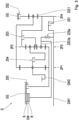
- the transmission G has an input shaft GW1, an output shaft GW2, a first planetary gear set P1, a second planetary gear set P2, a third planetary gear set P3 and an electric machine EM.
- the electric machine EM comprises a non-rotatable stator S and a rotatable rotor R.
- the drive shaft GW1 is not permanently connected to any of the planetary gear sets P1, P2, P3. Instead, the drive shaft GW1 can be connected to a carrier E1 of the third planetary gearset P3 by closing a first gear-forming shifting element S1, which carrier is constantly connected to a carrier of the second planetary gearset P2. A carrier of the first planetary gear set P1 is constantly connected to a ring gear of the third planetary gear set P3. The output shaft GW2 is constantly connected to a ring gear of the second planetary gear set P2. By closing a second gear-forming shifting element S2, the carrier E1 of the third planetary gear set P3 can be fixed in a rotationally fixed manner with respect to a housing GG.
- the second gear-forming shifting element S2 is designed as a positive-locking shifting element.
- a sun gear of the third planetary gear set P3 can be locked in a rotationally fixed manner.
- a fourth gear-forming shifting element S4 a ring gear of the first planetary gear set P1 can be fixed in a torque-proof manner.
- a fifth gear-forming shifting element S5 the ring gear of the first planetary gearset P1 can be connected to a sun gear of the second planetary gearset P2.
- a sixth gear-forming shifting element S6 the sun gear of the second planetary gearset P2 can be connected to the carrier of the first planetary gearset P1.
- the first and the third to sixth gear-forming shifting elements S1, S3, S4, S5, S6 are designed as non-positive shifting elements.
- the rotor R of the electrical machine EM is permanently connected to a sun gear E1 of the first planetary gear set P1 and can be connected to the drive shaft GW1 by closing an additional switching element ZS.
- the additional switching element ZS is designed as a form-fitting switching element.
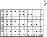
- FIG. 2 shows a shift pattern for the transmission G according to the first embodiment.
- Forward gears 1 to 8, one reverse gear 1R and six gears 1E1, 1E2, 1E3, 1E4, 1E5, 1E6 are specified in the lines of the shift pattern.
- the columns of the shift pattern are marked by a circle, which of the gear-forming shifting elements S1, S2, S3, S4, S5, S6 and the additional shifting element ZS for forming the forward gears 1 to 8, the reverse gear 1R and the gear stages 1E1, 1E2, 1E3, 1E4 , 1E5, 1E6 are to be closed.
- the transmission G has an input shaft GW1, an output shaft GW2, a first planetary gear set 2P1, a second planetary gear set 2P2, a third planetary gear set 2P3, a fourth planetary gear set 2P4 and an electric machine EM.
- the drive shaft GW1 is not permanently connected to any of the four planetary gear sets 2P1, 2P2, 2P3, 2P4. Instead, the drive shaft GW1 can be connected to a sun gear 22E1 of the fourth planetary gearset 2P4 by closing a first gear-forming shifting element 2S1, which is permanently connected to a ring gear of the second planetary gearset 2P2.
- the output shaft GW2 is permanently connected to a carrier of the first planetary gearset 2P1.
- a sun gear of the first planetary gear set 2P1 is continuously connected to a sun gear of the third planetary gear set 2P3.
- a ring gear of the first planetary gear set 2P1 is continuously connected to a carrier of the fourth planetary gear set 2P4.
- a sun gear of the second planetary gear set 2P2 is continuously connected to a ring gear of the third planetary gear set 2P3.
- a ring gear of the fourth planetary gearset 2P4 can be fixed in a rotationally fixed manner with respect to a housing GG.
- a third gear-forming shifting element 2S3 two elements of the second planetary gear set 2P2 can be connected to one another, here the sun gear and the ring gear.
- a carrier of the second planetary gearset 2P2 can be connected to the carrier of the first planetary gearset 2P1.
- gear-forming shifting element 2S5 By closing a fifth gear-forming shifting element 2S5, the sun gear of the first planetary gear set P1 can be locked in a rotationally fixed manner. All gear-forming shifting elements 2S1 to 2S5 are designed as non-positive shifting elements.
- a rotor R of the electrical machine EM is constantly connected to a web 22E2a of the third planetary gear set P3, and is connected by closing an additional switching element 2ZSa can be connected to the drive shaft GW1.
- the additional switching element 2ZSa is designed as a form-fitting switching element.
- the transmission G now has a fifth planetary gear set 2P5 in addition to the four planetary gear sets 2P1, 2P2, 2P3, 2P4.
- the drive shaft GW1 is now permanently connected to the carrier of the third planetary gear set 2P3, which is permanently connected to a carrier E3 of the fifth planetary gear set 2P5.
- the rotor R is now permanently connected to a ring gear 22E2b of the fifth planetary gear set 2P5.
- Closing additional shifting element 2ZSb enables torque to be transmitted between sun gear E4, carrier E3 and ring gear 22E2b of fifth planetary gear set 2P5. If the additional switching element 2ZSb is closed, the speed of the rotor R is increased compared to the speed of the drive shaft GW1.
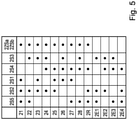
- figure 5 shows a shift pattern which is applicable to the transmission G according to the second embodiment.
- Forward gears 21 to 28, a reverse gear 2R and four gear stages 2E1, 2E2, 2E3, 2E4 are specified in the lines of the shift pattern.
- a circle in the columns of the shift pattern indicates which of the gear-forming shifting elements 2S1, 2S2, 2S3, 2S4, 2S5 and the additional shifting element 2ZSa, 2ZSb for forming the forward gears 21 to 28, the reverse gear 2R and the gear stages 2E1, 2E2, 2E3, 2E4 are to be closed.
- FIG. 6 shows a drive train for a motor vehicle with a transmission G, which, for example, corresponds to that in 3 illustrated second embodiment corresponds.
- the drive shaft GW1 is connected via a torsional vibration damper TS to a torque-transmitting interface GW1A of the transmission G, so that the interface GW1A and the drive shaft GW1 are torsionally elastically connected.
- the Interface GW1A can be designed, for example, as a spline or as a flange, to which a crankshaft of a transmission-external internal combustion engine VM can be connected.
- the output shaft GW2 of the transmission G is operatively connected to a differential gear AG, via which the power applied to the output shaft GW2 is distributed to the drive wheels DW of the motor vehicle.
Landscapes
- Engineering & Computer Science (AREA)
- Mechanical Engineering (AREA)
- Chemical & Material Sciences (AREA)
- Combustion & Propulsion (AREA)
- Transportation (AREA)
- General Engineering & Computer Science (AREA)
- Structure Of Transmissions (AREA)
- Hybrid Electric Vehicles (AREA)
- Automation & Control Theory (AREA)
Description
- Die Erfindung betrifft ein Getriebe für ein Kraftfahrzeug. Ein Getriebe bezeichnet hier insbesondere ein mehrgängiges Getriebe, bei dem eine Vielzahl von Gängen, also feste Übersetzungsverhältnisse zwischen der Antriebswelle und der Abtriebswelle des Getriebes, durch gangbildende Schaltelemente vorzugsweise automatisch schaltbar sind. Bei den gangbildenden Schaltelementen handelt es sich beispielsweise um Kupplungen oder Bremsen. Derartige Getriebe finden vor allem in Kraftfahrzeugen Anwendung, um die Drehzahl- und Drehmomentabgabecharakteristik der Antriebseinheit den Fahrwiderständen des Fahrzeugs in geeigneter Weise anzupassen. Die Erfindung betrifft ferner einen Antriebsstrang für ein Kraftfahrzeug mit einem solchen Getriebe, sowie ein Verfahren zum Betrieb eines solchen Getriebes oder eines solchen Antriebsstranges.
- Die Patentanmeldung
DE 10 2004 038 516 A1 offenbart ein derartiges Getriebe, welches eine Antriebswelle, eine Abtriebswelle, drei Planetenradsätze sowie sechs Schaltelemente umfasst. Durch selektives Schließen von drei der sechs Schaltelemente sind mehrere Gänge zwischen der Antriebswelle und der Abtriebswelle ausbildbar. - Aus der Patentanmeldung
DE 10 2006 033 087 A1 ist bekannt, eine elektrische Maschine an die Antriebswelle eines Getriebes anzubinden, um ein mit dem Getriebe ausgestattetes Kraftfahrzeug mittels der elektrischen Maschine anzutreiben. Um einen Verbrennungsmotor des Kraftfahrzeugs bei einem solchen elektrischen Antrieb nicht mitzuschleppen ist eine Kupplung vorgesehen, welche den Verbrennungsmotor von der Antriebswelle trennt. Diese Kupplung vergrößert den Bauraumbedarf des Getriebes. - Die Patentanmeldung
DE 10 2014 226 699 A1 schlägt eine alternative Anbindung des Elektromotors an das Getriebe vor. Der Elektromotor ist dabei mit einem Radsatzelement des Getriebes verbunden, welches mit der Antriebswelle über eine Lamellenkupplung verbunden ist. Die Lamellenkupplung dient zugleich als gangbildendes Schaltelement. Durch Offenhalten dieser Kupplung wird ein mit der Antriebswelle verbundener Verbrennungsmotor bei einem Antrieb mittels des Elektromotors nicht mitgeschleppt. Dies beschränkt jedoch die Zahl der Gangstufen, die für einen solchen elektrischen Antrieb zur Verfügung stehen. - Die Patentanmeldung
DE 10 2015 218 990 A1 beschreibt ein Getriebe für ein Kraftfahrzeug mit einer Antriebswelle, einer Abtriebswelle, drei Planetenradsätzen und sechs Schaltelementen. Durch selektives Schließen von drei der sechs Schaltelemente sind sieben Vorwärtsgänge zwischen der Antriebswelle und der Abtriebswelle schaltbar. - Es ist nun Aufgabe der Erfindung ein Getriebe bereitzustellen, welches sich einerseits durch kompakte Außenabmessungen und andererseits durch eine höhere Verfügbarkeit des elektrischen Antriebs auszeichnet. Eine weitere Aufgabe ist es, ein geeignetes Betriebsverfahren für ein solches Getriebe bereitzustellen.
- Die Aufgabe wird gelöst durch die Merkmale des Patentanspruchs 1. Patentanspruch 4 gibt eine Lösung der weiteren Aufgabe an. Vorteilhafte Ausgestaltungen ergeben sich aus den Unteransprüchen, der Beschreibung sowie aus den Figuren.
- Es wird ein Getriebe für ein Kraftfahrzeug vorgeschlagen, welches eine Antriebswelle, eine Abtriebswelle, eine elektrische Maschine, mehrere gangbildende Schaltelemente, eine Mehrzahl von Planetenradsätzen sowie eine drehmomentübertragende Schnittstelle zu einem getriebe-externen Verbrennungsmotor aufweist. Die drehmomentübertragende Schnittstelle kann beispielsweise eine Steckverzahnung oder ein Flansch sein. Das Getriebe ist dazu eingerichtet, durch selektives Schließen der gangbildenden Schaltelemente eine Mehrzahl von Gängen zwischen der Antriebswelle und der Abtriebswelle bereitzustellen.
- Die drehmomentübertragende Schnittstelle zum getriebe-externen Verbrennungsmotor ist mit der Antriebswelle ständig drehfest oder drehelastisch verbunden. In anderen Worten ist zwischen der Schnittstelle und der Antriebswelle keine schaltbare Kupplung vorgesehen. Es können ein oder mehrere Torsionsschwingungsdämpfer und/oder ein Drehschwingungstilger vorgesehen sein, um die drehelastische Verbindung bereitzustellen.
- Durch Schließen eines ersten der gangbildenden Schaltelemente werden die Antriebswelle und ein Element eines der Planetenradsätze in eine feste Drehzahlbeziehung zueinander gebracht. In anderen Worten ist ein Drehzahlverhältnis zwischen dem vorgenannten Element und der Antriebswelle im geschlossenen Zustand des ersten gangbildenden Schaltelements stets konstant. Das Drehzahlverhältnis kann den Wert Eins oder davon abweichende Werte annehmen. Ist das erste gangbildende Schaltelement geöffnet, so besteht keine Zwangsbeziehung zwischen den Drehzahlen des vorgenannten Elements und der Antriebswelle. Das erste gangbildende Schaltelement ist als kraftschlüssiges Schaltelement mit variabler Drehmomentübertragungsfähigkeit ausgebildet, also beispielsweise als Lamellenschaltelement.
- Ein anderes Element eines der Planetenradsätze ist mit einem Rotor der elektrischen Maschine ständig verbunden. Eine ständige Verbindung wird als Verbindung zwischen zwei Elementen bezeichnet, die stets besteht. Derart ständig verbundene Elemente drehen stets mit der gleichen Abhängigkeit zwischen deren Drehzahlen. In einer ständigen Verbindung zwischen zwei Elementen kann sich kein Schaltelement befinden. Eine ständige Verbindung ist daher von einer schaltbaren Verbindung zu unterscheiden.
- Erfindungsgemäß ist ein als formschlüssiges Schaltelement ausgebildetes Zusatzschaltelement vorgesehen, beispielsweise eine Klaue. Durch Schließen des Zusatzschaltelements werden der Rotor und die Antriebswelle in eine feste Drehzahlbeziehung zueinander gebracht. Ist das Zusatzschaltelement geöffnet, so besteht keine Zwangsbeziehung zwischen den Drehzahlen des vorgenannten anderen Elements und der Antriebswelle.
- Das zusätzlich zu den gangbildenden Schaltelementen vorgesehene Zusatzschaltelement weist aufgrund der Ausgestaltung als formschlüssiges Schaltelement einen geringen Bauraumbedarf auf. Für einen Antrieb mittels der elektrischen Maschine ohne gleichzeitigen Antrieb der Antriebswelle ist gemäß einer nicht-erfindungsgemäßen Ausführung das erste gangbildendende Schaltelement offen zu halten. Da der Rotor jedoch gemäß der nicht-erfindungsgemäßen Ausführung auf ein anderes Radsatzelement wirkt als das erste gangbildende Schaltelement, kann die Verfügbarkeit des Getriebes für einen Antrieb der Abtriebswelle mittels der elektrischen Maschine ohne gleichzeitigen Antrieb der Antriebswelle verbessert werden.
- Gemäß einer nicht-erfindungsgemäßen Ausführung besteht zwischen der Antriebswelle und den Planetenradsätzen keine ständige Verbindung. In anderen Worten ist zwischen der Antriebswelle und den Planetenradsätzen nur eine schaltbare Verbindung vorgesehen. Es können auch mehrere schaltbare Verbindungen zwischen der Antriebswelle und den Planetenradsätzen vorgesehen sein. Dadurch kann die Verfügbarkeit des Getriebes für einen Antrieb der Abtriebswelle mittels der elektrischen Maschine ohne gleichzeitigen Antrieb der Antriebswelle verbessert werden. Erfindungsgemäß besteht zwischen der Antriebswelle und einem Element eines der Planetenradsätze eine ständige Verbindung. In diesem Fall ist durch Schließen des Zusatzschaltelements ein anderes Element desselben Planetenradsatzes drehfest festsetzbar. Das Zusatzschaltelement ist somit als Bremse ausgeführt, wodurch der Bauaufwand des Getriebes reduziert werden kann. Erst durch Schließen des Zusatzschaltelements wird Drehmoment zwischen den Elementen des beteiligten Planetenradsatzes übertragen, welcher vorzugsweise das Element aufweist, mit dem der Rotor ständig verbunden ist.
- Das Getriebe kann Bestandteil eines Antriebsstrangs für ein Kraftfahrzeug sein. Der Antriebsstrang weist neben dem Getriebe auch einen Verbrennungsmotor auf. Die Abtriebswelle des Getriebes kann mit einem getriebe-internen oder getriebe-externen Differentialgetriebe wirkverbunden sein, welches mit Rädern des Kraftfahrzeugs wirkverbunden ist. Ein solcher Antriebsstrang ermöglicht mehrere Antriebsmodi des Kraftfahrzeugs. In einem elektrischen Fahrbetrieb wird das Kraftfahrzeug von der elektrischen Maschine des Getriebes angetrieben. In einem verbrennungsmotorischen Betrieb wird das Kraftfahrzeug vom Verbrennungsmotor angetrieben. In einem hybridischen Betrieb wird das Kraftfahrzeug sowohl vom Verbrennungsmotor als auch von der elektrischen Maschine des Getriebes angetrieben.
- Das Getriebe ist dazu eingerichtet, durch selektives Schließen der gangbildenden Schaltelemente eine Mehrzahl von Gängen zwischen der Antriebswelle und der Abtriebswelle bereitzustellen. Gemäß einem bevorzugten Betriebsverfahren ist das Zusatzschaltelement in all diesen Gängen geschlossen. Dadurch wird gewährleistet, dass die elektrische Maschine in all diesen Gängen Leistung in den Antriebsstrang abgeben, bzw. von diesem aufnehmen kann.
- Das Getriebe ist dazu eingerichtet, durch selektives Schließen einer Auswahl der gangbildenden Schaltelemente zumindest eine Gangstufe zwischen dem Rotor und der Abtriebswelle bereitzustellen. Bevorzugt können mehrere solche Gangstufen zwischen dem Rotor und der Abtriebswelle bereitgestellt werden. Gemäß einem nicht-erfindungsgemäßen Betriebsverfahren ist das Zusatzschaltelement in der zumindest einen Gangstufe, bevorzugt in all den Gangstufen geöffnet.
- Ausgehend von einem Betrieb des Getriebes in einer zuvor genannten Gangstufe kann in dem nicht erfindungsgemäßen Betriebsverfahren ein mit der Antriebswelle drehelastisch verbundener Verbrennungsmotor vom Stillstand auf eine Startdrehzahl beschleunigt werden, indem das erste gangbildende Schaltelement zumindest teilweise geschlossen wird. Dadurch kann der Verbrennungsmotor gestartet werden.
- Gemäß einer nicht erfindungsgemäßen Ausführung wird das erste gangbildende Schaltelement erst dann vollständig geschlossen, wenn nach erfolgter Beschleunigung des Verbrennungsmotors auf die Startdrehzahl das Zusatzschaltelement geschlossen ist. Unter "vollständigem Schließen" wird ein Vorgang verstanden, bei dem das Schaltelement so angesteuert wird, dass es ein hohes Maß an Drehmoment bei keiner oder nur geringer Differenzdrehzahl überträgt. Im Gegensatz dazu ist bei einem teilweisen Schließen des Schaltelements die Ausbildung einer Differenzdrehzahl ausdrücklich erwünscht, beispielsweise größer als 30 Umdrehungen pro Minute. Für das Schließen des Zusatzschaltelements müssen die über das Zusatzschaltelement verbundenen Getriebeelemente die gleiche Drehzahl aufweisen. Die dafür erforderliche Synchronisation kann durch entsprechende Steuerung des Verbrennungsmotors und/oder der elektrischen Maschine erfolgen.
- Vorzugsweise erfolgt in dieser nicht erfindungsgemäßen Ausführung das vollständige Schließen des ersten gangbildenden Schaltelements im Zuge eines Schaltvorgangs des Getriebes, bei dem ein weiteres der gangbildenden Schaltelemente geöffnet wird. Dadurch kann ausgehend von der zuvor eingelegten Gangstufe auf beispielsweise einen höheren Gang geschaltet werden, um eine Drehzahl des Verbrennungsmotors gering zu halten.
- Gemäß einer alternativen nicht erfindungsgemäßen Ausgestaltung wird das erste gangbildende Schaltelement nach der Beschleunigung des Verbrennungsmotors auf dessen Startdrehzahl vollständig geschlossen, wobei nachfolgend eines der an der zuvor eingelegten Gangstufe beteiligten gangbildenden Schaltelemente geöffnet wird. Das Zusatzschaltelement bleibt hierbei geöffnet. Dadurch kann ausgehend von einem rein elektrischen Antrieb der Abtriebswelle in einen hybridischen Betriebsmodus gewechselt werden, bei dem eine Leistungsverzweigung zwischen Abtriebswelle, Verbrennungsmotor und elektrischer Maschine erfolgt. In einem solchen Betriebsmodus ist ein stufenloser Betrieb des Getriebes möglich.
- Zur Steuerung der oben genannten Verfahren kann ein elektronisches Steuergerät vorgesehen sein, dass zumindest mit dem Getriebe, bevorzugt auch mit dem Verbrennungsmotor in Kommunikationsverbindung steht.
- Ein Ausführungsbeispiel der Erfindung ist nachfolgend anhand der beigefügten Figuren detailliert beschrieben. Es zeigen:
-
Fig. 1 ein Getriebe gemäß einem ersten nicht-erfindungsgemäßen Ausführungsbeispiel; -
Fig. 2 ein Schaltschema für das Getriebe gemäß dem ersten Ausführungsbeispiel; -
Fig. 3 undFig. 4 je ein Getriebe gemäß einem zweiten nicht-erfindungsgemäßen und einem erfindungsgemäßen Ausführungsbeispiel; -
Fig. 5 ein Schaltschema für die Getriebe gemäßFig. 3 ; und -
Fig. 6 einen Antriebsstrang für ein Kraftfahrzeug. -
Fig. 1 zeigt ein Getriebe G gemäß einem ersten nicht-erfindungsgemäßen Ausführungsbeispiel. Das Getriebe G weist eine Antriebswelle GW1, eine Abtriebswelle GW2, einen ersten Planetenradsatz P1, einen zweiten Planetenradsatz P2, einen dritten Planetenradsatz P3 und eine elektrische Maschine EM auf. Die elektrische Maschine EM umfasst einen drehfesten Stator S und einen drehbaren Rotor R. - Die Antriebswelle GW1 ist mit keinem der Planetenradsätze P1, P2, P3 ständig verbunden. Stattdessen ist die Antriebswelle GW1 durch Schließen eines ersten gangbildenden Schaltelements S1 mit einem Steg E1 des dritten Planetenradsatzes P3 verbindbar, welcher mit einem Steg des zweiten Planetenradsatzes P2 ständig verbunden ist. Ein Steg des ersten Planetenradsatzes P1 ist mit einem Hohlrad des dritten Planetenradsatzes P3 ständig verbunden. Die Abtriebswelle GW2 ist mit einem Hohlrad des zweiten Planetenradsatzes P2 ständig verbunden. Durch Schließen eines zweiten gangbildenden Schaltelements S2 ist der Steg E1 des dritten Planetenradsatzes P3 gegenüber einem Gehäuse GG drehfest festsetzbar. Das zweite gangbildende Schaltelement S2 ist als formschlüssiges Schaltelement ausgebildet. Durch Schließen eines dritten gangbildenden Schaltelements S3 ist ein Sonnenrad des dritten Planetenradsatzes P3 drehfest festsetzbar. Durch Schließen eines vierten gangbildenden Schaltelements S4 ist ein Hohlrad des ersten Planetenradsatzes P1 drehfest festsetzbar. Durch Schließen eines fünften gangbildenden Schaltelements S5 ist das Hohlrad des ersten Planetenradsatzes P1 mit einem Sonnenrad des zweiten Planetenradsatzes P2 verbindbar. Durch Schließen eines sechsten gangbildenden Schaltelements S6 ist das Sonnenrad des zweiten Planetenradsatzes P2 mit dem Steg des ersten Planetenradsatzes P1 verbindbar. Das erste sowie das dritte bis sechste gangbildende Schaltelement S1, S3, S4, S5, S6 sind als kraftschlüssige Schaltelemente ausgebildet. Der Rotor R der elektrischen Maschine EM ist mit einem Sonnenrad E1 des ersten Planetenradsatzes P1 ständig verbunden, und ist durch Schließen eines Zusatzschaltelements ZS mit der Antriebswelle GW1 verbindbar.
- Das Zusatzschaltelements ZS ist als formschlüssiges Schaltelement ausgebildet.
-
Fig. 2 zeigt ein Schaltschema für das Getriebe G gemäß dem ersten Ausführungsbeispiel. In den Zeilen des Schaltschemas sind Vorwärtsgänge 1 bis 8, ein Rückwärtsgang 1R sowie sechs Gangstufen 1E1, 1E2, 1E3, 1E4, 1E5, 1E6 angegeben. In den Spalten des Schaltschemas ist durch einen Kreis gekennzeichnet, welche der gangbildenden Schaltelemente S1, S2, S3, S4, S5, S6 und des Zusatzschaltelements ZS zur Bildung der Vorwärtsgänge 1 bis 8, des Rückwärtsgangs 1R und der Gangstufen 1E1, 1E2, 1E3, 1E4, 1E5, 1E6 zu schließen sind. -
Fig. 3 zeigt ein Getriebe G gemäß einem zweiten nicht-erfindungsgemäßen Ausführungsbeispiel. Das Getriebe G weist eine Antriebswelle GW1, eine Abtriebswelle GW2, einen ersten Planetenradsatz 2P1, einen zweiten Planetenradsatz 2P2, einen dritten Planetenradsatz 2P3, einen vierten Planetenradsatz 2P4 und eine elektrische Maschine EM auf. - Die Antriebswelle GW1 ist mit keinem der vier Planetenradsätze 2P1, 2P2, 2P3, 2P4 ständig verbunden. Stattdessen ist die Antriebswelle GW1 durch Schließen eines ersten gangbildenden Schaltelements 2S1 mit einem Sonnenrad 22E1 des vierten Planetenradsatzes 2P4 verbindbar, welches mit einem Hohlrad des zweiten Planetenradsatzes 2P2 ständig verbunden ist. Die Abtriebswelle GW2 ist mit einem Steg des ersten Planetenradsatzes 2P1 ständig verbunden. Ein Sonnenrad des ersten Planetenradsatzes 2P1 ist mit einem Sonnenrad des dritten Planetenradsatzes 2P3 ständig verbunden. Ein Hohlrad des ersten Planetenradsatzes 2P1 ist mit einem Steg des vierten Planetenradsatzes 2P4 ständig verbunden. Ein Sonnenrad des zweiten Planetenradsatzes 2P2 ist mit einem Hohlrad des dritten Planetenradsatzes 2P3 ständig verbunden. Durch Schließen eines zweiten gangbildenden Schaltelements 2S2 ist ein Hohlrad des vierten Planetenradsatzes 2P4 gegenüber einem Gehäuse GG drehfest festsetzbar. Durch Schließen eines dritten gangbildenden Schaltelements 2S3 sind zwei Elemente des zweiten Planetenradsatzes 2P2 miteinander verbindbar, hier das Sonnenrad und das Hohlrad. Durch Schließen eines vierten gangbildenden Schaltelements 2S4 ist ein Steg des zweiten Planetenradsatzes 2P2 mit dem Steg des ersten Planetenradsatzes 2P1 verbindbar. Durch Schließen eines fünften gangbildenden Schaltelements 2S5 ist das Sonnenrad des ersten Planetenradsatzes P1 drehfest festsetzbar. Sämtliche gangbildenden Schaltelemente 2S1 bis 2S5 sind als kraftschlüssige Schaltelemente ausgebildet. Ein Rotor R der elektrischen Maschine EM ist mit einem Steg 22E2a des dritten Planetenradsatzes P3 ständig verbunden, und ist durch Schließen eines Zusatzschaltelements 2ZSa mit der Antriebswelle GW1 verbindbar. Das Zusatzschaltelements 2ZSa ist als formschlüssiges Schaltelement ausgebildet.
-
Fig. 4 zeigt ein Getriebe G gemäß einem erfindungsgemäßen Ausführungsbeispiel der Erfindung, welches dem inFig. 3 dargestellten zweiten Ausführungsbeispiel im Wesentlichen entspricht. Das Getriebe G weist nun neben den vier Planetenradsätzen 2P1, 2P2, 2P3, 2P4 einen fünften Planetenradradsatz 2P5 auf. Die Antriebswelle GW1 ist mit dem Steg des dritten Planetenradsatzes 2P3 nun ständig verbunden, welcher mit einem Steg E3 des fünften Planetenradsatzes 2P5 ständig verbunden ist. Der Rotor R ist nun mit einem Hohlrad 22E2b des fünften Planetenradsatzes 2P5 ständig verbunden. Durch Schließen eines Zusatzschaltelements 2ZSb ist ein Sonnenrad E4 des fünften Planetenradsatzes 2P5 gegenüber dem Gehäuse GG drehfest festsetzbar. Durch Schließen des Zusatzschaltelements 2ZSb wird eine Drehmomentübertragung zwischen Sonnenrad E4, Steg E3 und Hohlrad 22E2b des fünften Planetenradsatzes 2P5 ermöglicht. Ist das Zusatzschaltelement 2ZSb geschlossen, so wird eine Drehzahl des Rotors R im Vergleich zu einer Drehzahl der Antriebswelle GW1 vergrößert. -
Fig. 5 zeigt ein Schaltschema, welches für das Getriebe G gemäß dem zweiten Ausführungsbeispiel anwendbar ist. In den Zeilen des Schaltschemas sind Vorwärtsgänge 21 bis 28, ein Rückwärtsgang 2R sowie vier Gangstufen 2E1, 2E2, 2E3, 2E4 angegeben. In den Spalten des Schaltschemas ist durch einen Kreis gekennzeichnet, welche der gangbildenden Schaltelemente 2S1, 2S2, 2S3, 2S4, 2S5 und des Zusatzschaltelements 2ZSa, 2ZSb zur Bildung der Vorwärtsgänge 21 bis 28, des Rückwärtsgangs 2R und der Gangstufen 2E1, 2E2, 2E3, 2E4 zu schließen sind. -
Fig. 6 zeigt einen Antriebsstrang für ein Kraftfahrzeug mit einem Getriebe G, welches beispielhaft dem inFig. 3 dargestellten zweiten Ausführungsbeispiel entspricht. Die Antriebswelle GW1 ist über einen Torsionsschwingungsdämpfer TS mit einer drehmomentübertragenden Schnittstelle GW1A des Getriebes G verbunden, sodass die Schnittstelle GW1A und die Antriebswelle GW1 drehelastisch verbunden sind. Die Schnittstelle GW1A kann beispielsweise als eine Steckverzahnung oder als ein Flansch ausgebildet sein, woran eine Kurbelwelle eines getriebe-externen Verbrennungsmotors VM anschließbar ist. Die Abtriebswelle GW2 des Getriebes G ist mit einem Differentialgetriebe AG wirkverbunden, über welches die an der Abtriebswelle GW2 anliegende Leistung auf Antriebsräder DW des Kraftfahrzeugs verteilt wird. -
- G
- Getriebe
- GW1
- Antriebswelle
- GW2
- Abtriebswelle
- GW1A
- Schnittstelle
- EM
- Elektrische Maschine
- S
- Stator
- R
- Rotor
- P1
- Erster Planetenradsatz
- P2
- Zweiter Planetenradsatz
- P3
- Dritter Planetenradsatz
- E1
- Element
- E2
- Element
- S1
- Erstes gangbildendes Schaltelement
- S2
- Zweites gangbildendes Schaltelement
- S3
- Drittes gangbildendes Schaltelement
- S4
- Viertes gangbildendes Schaltelement
- S5
- Fünftes gangbildendes Schaltelement
- ZS
- Zusatzschaltelement
- 1 bis 8
- Gang
- 1R
- Gang
- 1E1 bis 1E6
- Gangstufe
- 2P1
- Erster Planetenradsatz
- 2P2
- Zweiter Planetenradsatz
- 2P3
- Dritter Planetenradsatz
- 2P4
- Vierter Planetenradsatz
- 2P5
- Fünfter Planetenradsatz
- 22E1
- Element
- 22E2a
- Element
- 22E2b
- Element
- E4
- Element
- E5
- Element
- 21 bis 28
- Gang
- 2R
- Gang
- 2E1 bis 1E4
- Gangstufe
- 2ZSa, 2ZSb
- Zusatzschaltelement
- VM
- Verbrennungsmotor
- TS
- Torsionsschwingungsdämpfer
- AG
- Differentialgetriebe
- DW
- Antriebsrad
Claims (4)
- Getriebe (G) für ein Kraftfahrzeug, wobei das Getriebe (G) eine Antriebswelle (GW1), eine Abtriebswelle (GW2), eine elektrische Maschine (EM), eine drehmomentübertragende Schnittstelle (GW1A) zu einem getriebe-externen Verbrennungsmotor (VM) sowie eine Mehrzahl von Planetenradsätzen (P1-P3; 2P1-2P5) aufweist, wobei das Getriebe (G) dazu eingerichtet ist durch selektives Schließen von gangbildenden Schaltelementen (S1-S6; 2S1-2S5) eine Mehrzahl von Gängen (1-8, 1R; 21-28, 2R) zwischen der Antriebswelle (GW1) und der Abtriebswelle (GW2) bereitzustellen,- wobei die drehmomentübertragende Schnittstelle (GW1A) mit der Antriebswelle (GW1) ständig drehfest oder drehelastisch verbunden ist,- wobei durch Schließen eines ersten der gangbildenden Schaltelemente (S1, 2S1), welches als kraftschlüssiges Schaltelement mit variabler Drehmomentübertragungsfähigkeit ausgebildet ist, die Antriebswelle (GW1) und ein Element (E1, 22E1) eines der Planetenradsätze (P3; 2P4) in eine feste Drehzahlbeziehung zueinander bringbar sind,- wobei ein anderes Element (E2, 22E2a, 22E2b) eines der Planetenradsätze (P1, 2P3, 2P5) mit einem Rotor (R) der elektrischen Maschine (EM) ständig verbunden ist,- wobei durch Schließen eines Zusatzschaltelements (ZS, 2ZSa, 2ZSb), welches als formschlüssiges Schaltelement ausgebildet ist, der Rotor (R) und die Antriebswelle (GW1) in eine feste Drehzahlbeziehung zueinander bringbar sind,dadurch gekennzeichnet, dass zwischen der Antriebswelle (GW1) und einem Element (E3) eines der Planetenradsätze (2P5) eine ständige Verbindung besteht, wobei durch Schließen des Zusatzschaltelements (2ZSb) ein anderes Element (E4) desselben Planetenradsatzes (2P5) drehfest festsetzbar ist.
- Getriebe (G) nach Anspruch 1, dadurch gekennzeichnet, dass jener der Planetenradsätze (2P5), dessen Element (E3) mit der Antriebswelle (GW1) ständig verbunden ist, das Element (22E2b) aufweist, mit dem der Rotor (R) ständig verbunden ist.
- Antriebsstrang für ein Kraftfahrzeug, gekennzeichnet durch ein Getriebe (G) gemäß einem der vorangehenden Ansprüche.
- Verfahren zum Betrieb eines Getriebes (G) nach Anspruch 1 oder Anspruch 2 oder eines Antriebsstranges nach Anspruch 3, dadurch gekennzeichnet, dass durch selektives Schließen der gangbildenden Schaltelemente (S1-S6; 2S1-2S5) eine Mehrzahl von Gängen (1-8, 1R; 21-28, 2R) zwischen der Antriebswelle (GW1) und der Abtriebswelle (GW2) ausbildbar sind, wobei das Zusatzschaltelement (ZS, 2ZSa, 2ZSb) in jedem dieser Gänge (1-8, 1R; 21-28, 2R) geschlossen ist.
Applications Claiming Priority (2)
| Application Number | Priority Date | Filing Date | Title |
|---|---|---|---|
| DE102017222300.6A DE102017222300A1 (de) | 2017-12-08 | 2017-12-08 | Getriebe für ein Kraftfahrzeug sowie Verfahren zum Betrieb eines Getriebes |
| PCT/EP2018/083561 WO2019110626A1 (de) | 2017-12-08 | 2018-12-05 | Getriebe für ein kraftfahrzeug, antriebsstrang, sowie verfahren zum betrieb eines getriebes |
Publications (2)
| Publication Number | Publication Date |
|---|---|
| EP3720730A1 EP3720730A1 (de) | 2020-10-14 |
| EP3720730B1 true EP3720730B1 (de) | 2022-01-26 |
Family
ID=64870392
Family Applications (1)
| Application Number | Title | Priority Date | Filing Date |
|---|---|---|---|
| EP18825879.2A Not-in-force EP3720730B1 (de) | 2017-12-08 | 2018-12-05 | Getriebe für ein kraftfahrzeug, antriebsstrang, sowie verfahren zum betrieb eines getriebes |
Country Status (5)
| Country | Link |
|---|---|
| US (1) | US11254199B2 (de) |
| EP (1) | EP3720730B1 (de) |
| CN (1) | CN111448092B (de) |
| DE (1) | DE102017222300A1 (de) |
| WO (1) | WO2019110626A1 (de) |
Family Cites Families (14)
| Publication number | Priority date | Publication date | Assignee | Title |
|---|---|---|---|---|
| DE102004038516A1 (de) | 2004-08-07 | 2006-02-23 | Zf Friedrichshafen Ag | Mehrstufengetriebe |
| DE102006033087B4 (de) | 2006-07-14 | 2022-05-19 | Zf Friedrichshafen Ag | Hybridantrieb für ein Fahrzeug |
| DE102013201182A1 (de) * | 2013-01-25 | 2014-07-31 | Zf Friedrichshafen Ag | Mehrstufengetriebe |
| JP5942228B2 (ja) * | 2013-11-22 | 2016-06-29 | ジヤトコ株式会社 | 自動変速機 |
| DE102014208873A1 (de) * | 2014-05-12 | 2015-11-12 | Zf Friedrichshafen Ag | Verfahren zum Betrieb eines Getriebes |
| DE102014226699B4 (de) | 2014-12-19 | 2024-10-24 | Zf Friedrichshafen Ag | Getriebe für ein Kraftfahrzeug und Antriebsstrang |
| DE102015204573A1 (de) * | 2015-03-13 | 2016-09-15 | Zf Friedrichshafen Ag | Mehrstufengetriebe für einen Hybridantrieb eines Kraftfahrzeugs |
| DE102015209050A1 (de) * | 2015-05-18 | 2016-11-24 | Zf Friedrichshafen Ag | Getriebe für ein Kraftfahrzeug, Antriebsstrang für ein Hybridfahrzeug, und Verfahren zum Betrieb eines solchen Antriebsstranges |
| DE102015210251A1 (de) * | 2015-06-03 | 2016-12-08 | Zf Friedrichshafen Ag | Getriebe für ein Kraftfahrzeug, sowie Antriebstrang für ein Hybridfahrzeug mit einem solchen Getriebe |
| DE102015210248A1 (de) * | 2015-06-03 | 2016-12-08 | Zf Friedrichshafen Ag | Getriebevorrichtung mit einer elektrischen Maschine |
| DE102015218583A1 (de) * | 2015-09-28 | 2017-03-30 | Zf Friedrichshafen Ag | Getriebe für ein Kraftfahrzeug, sowie Antriebsstrang für ein Kraftfahrzeug |
| DE102015218990A1 (de) * | 2015-10-01 | 2017-04-06 | Zf Friedrichshafen Ag | Getriebe für ein Kraftfahrzeug, sowie Antriebsstrang für ein Kraftfahrzeug |
| DE102015223290A1 (de) * | 2015-11-25 | 2017-06-01 | Zf Friedrichshafen Ag | Getriebe für ein Kraftfahrzeug, sowie Antriebsstrang für ein Kraftfahrzeug mit einem solchen Getriebe |
| DE102016208669A1 (de) * | 2016-05-19 | 2017-11-23 | Zf Friedrichshafen Ag | Getriebe für ein Kraftfahrzeug, sowie Antriebsstrang für ein Kraftfahrzeug |
-
2017
- 2017-12-08 DE DE102017222300.6A patent/DE102017222300A1/de not_active Withdrawn
-
2018
- 2018-12-05 US US16/770,456 patent/US11254199B2/en not_active Expired - Fee Related
- 2018-12-05 WO PCT/EP2018/083561 patent/WO2019110626A1/de not_active Ceased
- 2018-12-05 CN CN201880079335.3A patent/CN111448092B/zh not_active Expired - Fee Related
- 2018-12-05 EP EP18825879.2A patent/EP3720730B1/de not_active Not-in-force
Also Published As
| Publication number | Publication date |
|---|---|
| CN111448092A (zh) | 2020-07-24 |
| EP3720730A1 (de) | 2020-10-14 |
| US11254199B2 (en) | 2022-02-22 |
| US20210162984A1 (en) | 2021-06-03 |
| WO2019110626A1 (de) | 2019-06-13 |
| CN111448092B (zh) | 2023-07-25 |
| DE102017222300A1 (de) | 2019-06-13 |
Similar Documents
| Publication | Publication Date | Title |
|---|---|---|
| DE102017204970B3 (de) | Kombiniertes Mehrstufen-Hybridgetriebe | |
| DE102016217248A1 (de) | Getriebe für ein Kraftfahrzeug, sowie Antriebsstrang für ein Kraftfahrzeug | |
| EP3295055A1 (de) | Getriebe für ein kraftfahrzeug und hybridantriebsstrang damit | |
| EP3171054B1 (de) | Getriebe für ein kraftfahrzeug, sowie antriebsstrang für ein kraftfahrzeug | |
| WO2017089143A1 (de) | Getriebe für ein kraftfahrzeug, sowie antriebsstrang für ein kraftfahrzeug mit einem solchen getriebe | |
| DE102017204971B3 (de) | Mehrstufen-Hybridgetriebe | |
| DE102014220942A1 (de) | Getriebe für ein Kraftfahrzeug | |
| DE102014220967A1 (de) | Getriebe für ein Kraftfahrzeug | |
| WO2020048711A1 (de) | Getriebe für ein kraftfahrzeug, kraftfahrzeuganstriebsstrang und verfahren zum betreiben eines getriebes | |
| DE102017216317B4 (de) | Getriebe für ein Kraftfahrzeug | |
| WO2016030102A1 (de) | Getriebe | |
| DE102014220963A1 (de) | Getriebe für ein Kraftfahrzeug | |
| EP3720730B1 (de) | Getriebe für ein kraftfahrzeug, antriebsstrang, sowie verfahren zum betrieb eines getriebes | |
| DE102017222717A1 (de) | Getriebe für ein Kraftfahrzeug | |
| WO2017092997A1 (de) | Getriebe für ein kraftfahrzeug, sowie antriebsstrang für ein kraftfahrzeug mit einem solchen getriebe | |
| DE102017222723A1 (de) | Getriebe für ein Kraftfahrzeug | |
| DE102018200295B4 (de) | Getriebe für ein Kraftfahrzeug | |
| DE102016207439A1 (de) | Getriebe für ein Kraftfahrzeug, sowie Antriebsstrang für ein Kraftfahrzeug mit einem solchen Getriebe | |
| DE102017216308B4 (de) | Getriebe für ein Kraftfahrzeug | |
| WO2016030101A1 (de) | Getriebe | |
| DE102016211891B4 (de) | Getriebe für ein Kraftfahrzeug, sowie Antriebsstrang für ein Kraftfahrzeug | |
| DE102014220941A1 (de) | Getriebe für ein Kraftfahrzeug | |
| DE102018200294B4 (de) | Getriebe für ein Kraftfahrzeug | |
| DE102017223151A1 (de) | Getriebe für ein Kraftfahrzeug | |
| DE102018200297B4 (de) | Getriebe für ein Kraftfahrzeug |
Legal Events
| Date | Code | Title | Description |
|---|---|---|---|
| STAA | Information on the status of an ep patent application or granted ep patent |
Free format text: STATUS: UNKNOWN |
|
| STAA | Information on the status of an ep patent application or granted ep patent |
Free format text: STATUS: THE INTERNATIONAL PUBLICATION HAS BEEN MADE |
|
| PUAI | Public reference made under article 153(3) epc to a published international application that has entered the european phase |
Free format text: ORIGINAL CODE: 0009012 |
|
| STAA | Information on the status of an ep patent application or granted ep patent |
Free format text: STATUS: REQUEST FOR EXAMINATION WAS MADE |
|
| 17P | Request for examination filed |
Effective date: 20200518 |
|
| AK | Designated contracting states |
Kind code of ref document: A1 Designated state(s): AL AT BE BG CH CY CZ DE DK EE ES FI FR GB GR HR HU IE IS IT LI LT LU LV MC MK MT NL NO PL PT RO RS SE SI SK SM TR |
|
| AX | Request for extension of the european patent |
Extension state: BA ME |
|
| DAV | Request for validation of the european patent (deleted) | ||
| DAX | Request for extension of the european patent (deleted) | ||
| GRAP | Despatch of communication of intention to grant a patent |
Free format text: ORIGINAL CODE: EPIDOSNIGR1 |
|
| STAA | Information on the status of an ep patent application or granted ep patent |
Free format text: STATUS: GRANT OF PATENT IS INTENDED |
|
| INTG | Intention to grant announced |
Effective date: 20210908 |
|
| GRAS | Grant fee paid |
Free format text: ORIGINAL CODE: EPIDOSNIGR3 |
|
| GRAA | (expected) grant |
Free format text: ORIGINAL CODE: 0009210 |
|
| STAA | Information on the status of an ep patent application or granted ep patent |
Free format text: STATUS: THE PATENT HAS BEEN GRANTED |
|
| AK | Designated contracting states |
Kind code of ref document: B1 Designated state(s): AL AT BE BG CH CY CZ DE DK EE ES FI FR GB GR HR HU IE IS IT LI LT LU LV MC MK MT NL NO PL PT RO RS SE SI SK SM TR |
|
| REG | Reference to a national code |
Ref country code: GB Ref legal event code: FG4D Free format text: NOT ENGLISH |
|
| REG | Reference to a national code |
Ref country code: CH Ref legal event code: EP |
|
| REG | Reference to a national code |
Ref country code: AT Ref legal event code: REF Ref document number: 1465010 Country of ref document: AT Kind code of ref document: T Effective date: 20220215 |
|
| REG | Reference to a national code |
Ref country code: IE Ref legal event code: FG4D Free format text: LANGUAGE OF EP DOCUMENT: GERMAN |
|
| REG | Reference to a national code |
Ref country code: DE Ref legal event code: R096 Ref document number: 502018008679 Country of ref document: DE |
|
| REG | Reference to a national code |
Ref country code: LT Ref legal event code: MG9D |
|
| REG | Reference to a national code |
Ref country code: NL Ref legal event code: MP Effective date: 20220126 |
|
| PG25 | Lapsed in a contracting state [announced via postgrant information from national office to epo] |
Ref country code: NL Free format text: LAPSE BECAUSE OF FAILURE TO SUBMIT A TRANSLATION OF THE DESCRIPTION OR TO PAY THE FEE WITHIN THE PRESCRIBED TIME-LIMIT Effective date: 20220126 |
|
| PG25 | Lapsed in a contracting state [announced via postgrant information from national office to epo] |
Ref country code: SE Free format text: LAPSE BECAUSE OF FAILURE TO SUBMIT A TRANSLATION OF THE DESCRIPTION OR TO PAY THE FEE WITHIN THE PRESCRIBED TIME-LIMIT Effective date: 20220126 Ref country code: RS Free format text: LAPSE BECAUSE OF FAILURE TO SUBMIT A TRANSLATION OF THE DESCRIPTION OR TO PAY THE FEE WITHIN THE PRESCRIBED TIME-LIMIT Effective date: 20220126 Ref country code: PT Free format text: LAPSE BECAUSE OF FAILURE TO SUBMIT A TRANSLATION OF THE DESCRIPTION OR TO PAY THE FEE WITHIN THE PRESCRIBED TIME-LIMIT Effective date: 20220526 Ref country code: NO Free format text: LAPSE BECAUSE OF FAILURE TO SUBMIT A TRANSLATION OF THE DESCRIPTION OR TO PAY THE FEE WITHIN THE PRESCRIBED TIME-LIMIT Effective date: 20220426 Ref country code: LT Free format text: LAPSE BECAUSE OF FAILURE TO SUBMIT A TRANSLATION OF THE DESCRIPTION OR TO PAY THE FEE WITHIN THE PRESCRIBED TIME-LIMIT Effective date: 20220126 Ref country code: HR Free format text: LAPSE BECAUSE OF FAILURE TO SUBMIT A TRANSLATION OF THE DESCRIPTION OR TO PAY THE FEE WITHIN THE PRESCRIBED TIME-LIMIT Effective date: 20220126 Ref country code: ES Free format text: LAPSE BECAUSE OF FAILURE TO SUBMIT A TRANSLATION OF THE DESCRIPTION OR TO PAY THE FEE WITHIN THE PRESCRIBED TIME-LIMIT Effective date: 20220126 Ref country code: BG Free format text: LAPSE BECAUSE OF FAILURE TO SUBMIT A TRANSLATION OF THE DESCRIPTION OR TO PAY THE FEE WITHIN THE PRESCRIBED TIME-LIMIT Effective date: 20220426 |
|
| PG25 | Lapsed in a contracting state [announced via postgrant information from national office to epo] |
Ref country code: PL Free format text: LAPSE BECAUSE OF FAILURE TO SUBMIT A TRANSLATION OF THE DESCRIPTION OR TO PAY THE FEE WITHIN THE PRESCRIBED TIME-LIMIT Effective date: 20220126 Ref country code: LV Free format text: LAPSE BECAUSE OF FAILURE TO SUBMIT A TRANSLATION OF THE DESCRIPTION OR TO PAY THE FEE WITHIN THE PRESCRIBED TIME-LIMIT Effective date: 20220126 Ref country code: GR Free format text: LAPSE BECAUSE OF FAILURE TO SUBMIT A TRANSLATION OF THE DESCRIPTION OR TO PAY THE FEE WITHIN THE PRESCRIBED TIME-LIMIT Effective date: 20220427 Ref country code: FI Free format text: LAPSE BECAUSE OF FAILURE TO SUBMIT A TRANSLATION OF THE DESCRIPTION OR TO PAY THE FEE WITHIN THE PRESCRIBED TIME-LIMIT Effective date: 20220126 |
|
| PG25 | Lapsed in a contracting state [announced via postgrant information from national office to epo] |
Ref country code: IS Free format text: LAPSE BECAUSE OF FAILURE TO SUBMIT A TRANSLATION OF THE DESCRIPTION OR TO PAY THE FEE WITHIN THE PRESCRIBED TIME-LIMIT Effective date: 20220526 |
|
| REG | Reference to a national code |
Ref country code: DE Ref legal event code: R097 Ref document number: 502018008679 Country of ref document: DE |
|
| PG25 | Lapsed in a contracting state [announced via postgrant information from national office to epo] |
Ref country code: SM Free format text: LAPSE BECAUSE OF FAILURE TO SUBMIT A TRANSLATION OF THE DESCRIPTION OR TO PAY THE FEE WITHIN THE PRESCRIBED TIME-LIMIT Effective date: 20220126 Ref country code: SK Free format text: LAPSE BECAUSE OF FAILURE TO SUBMIT A TRANSLATION OF THE DESCRIPTION OR TO PAY THE FEE WITHIN THE PRESCRIBED TIME-LIMIT Effective date: 20220126 Ref country code: RO Free format text: LAPSE BECAUSE OF FAILURE TO SUBMIT A TRANSLATION OF THE DESCRIPTION OR TO PAY THE FEE WITHIN THE PRESCRIBED TIME-LIMIT Effective date: 20220126 Ref country code: EE Free format text: LAPSE BECAUSE OF FAILURE TO SUBMIT A TRANSLATION OF THE DESCRIPTION OR TO PAY THE FEE WITHIN THE PRESCRIBED TIME-LIMIT Effective date: 20220126 Ref country code: DK Free format text: LAPSE BECAUSE OF FAILURE TO SUBMIT A TRANSLATION OF THE DESCRIPTION OR TO PAY THE FEE WITHIN THE PRESCRIBED TIME-LIMIT Effective date: 20220126 Ref country code: CZ Free format text: LAPSE BECAUSE OF FAILURE TO SUBMIT A TRANSLATION OF THE DESCRIPTION OR TO PAY THE FEE WITHIN THE PRESCRIBED TIME-LIMIT Effective date: 20220126 |
|
| PG25 | Lapsed in a contracting state [announced via postgrant information from national office to epo] |
Ref country code: AL Free format text: LAPSE BECAUSE OF FAILURE TO SUBMIT A TRANSLATION OF THE DESCRIPTION OR TO PAY THE FEE WITHIN THE PRESCRIBED TIME-LIMIT Effective date: 20220126 |
|
| PLBE | No opposition filed within time limit |
Free format text: ORIGINAL CODE: 0009261 |
|
| STAA | Information on the status of an ep patent application or granted ep patent |
Free format text: STATUS: NO OPPOSITION FILED WITHIN TIME LIMIT |
|
| 26N | No opposition filed |
Effective date: 20221027 |
|
| PG25 | Lapsed in a contracting state [announced via postgrant information from national office to epo] |
Ref country code: SI Free format text: LAPSE BECAUSE OF FAILURE TO SUBMIT A TRANSLATION OF THE DESCRIPTION OR TO PAY THE FEE WITHIN THE PRESCRIBED TIME-LIMIT Effective date: 20220126 |
|
| P01 | Opt-out of the competence of the unified patent court (upc) registered |
Effective date: 20230528 |
|
| PG25 | Lapsed in a contracting state [announced via postgrant information from national office to epo] |
Ref country code: IT Free format text: LAPSE BECAUSE OF FAILURE TO SUBMIT A TRANSLATION OF THE DESCRIPTION OR TO PAY THE FEE WITHIN THE PRESCRIBED TIME-LIMIT Effective date: 20220126 |
|
| REG | Reference to a national code |
Ref country code: CH Ref legal event code: PL |
|
| GBPC | Gb: european patent ceased through non-payment of renewal fee |
Effective date: 20221205 |
|
| REG | Reference to a national code |
Ref country code: BE Ref legal event code: MM Effective date: 20221231 |
|
| PG25 | Lapsed in a contracting state [announced via postgrant information from national office to epo] |
Ref country code: LU Free format text: LAPSE BECAUSE OF NON-PAYMENT OF DUE FEES Effective date: 20221205 |
|
| PG25 | Lapsed in a contracting state [announced via postgrant information from national office to epo] |
Ref country code: LI Free format text: LAPSE BECAUSE OF NON-PAYMENT OF DUE FEES Effective date: 20221231 Ref country code: IE Free format text: LAPSE BECAUSE OF NON-PAYMENT OF DUE FEES Effective date: 20221205 Ref country code: GB Free format text: LAPSE BECAUSE OF NON-PAYMENT OF DUE FEES Effective date: 20221205 Ref country code: CH Free format text: LAPSE BECAUSE OF NON-PAYMENT OF DUE FEES Effective date: 20221231 |
|
| PG25 | Lapsed in a contracting state [announced via postgrant information from national office to epo] |
Ref country code: FR Free format text: LAPSE BECAUSE OF NON-PAYMENT OF DUE FEES Effective date: 20221231 Ref country code: BE Free format text: LAPSE BECAUSE OF NON-PAYMENT OF DUE FEES Effective date: 20221231 |
|
| PGFP | Annual fee paid to national office [announced via postgrant information from national office to epo] |
Ref country code: DE Payment date: 20231010 Year of fee payment: 6 |
|
| PG25 | Lapsed in a contracting state [announced via postgrant information from national office to epo] |
Ref country code: CY Free format text: LAPSE BECAUSE OF FAILURE TO SUBMIT A TRANSLATION OF THE DESCRIPTION OR TO PAY THE FEE WITHIN THE PRESCRIBED TIME-LIMIT Effective date: 20220126 |
|
| PG25 | Lapsed in a contracting state [announced via postgrant information from national office to epo] |
Ref country code: MK Free format text: LAPSE BECAUSE OF FAILURE TO SUBMIT A TRANSLATION OF THE DESCRIPTION OR TO PAY THE FEE WITHIN THE PRESCRIBED TIME-LIMIT Effective date: 20220126 Ref country code: HU Free format text: LAPSE BECAUSE OF FAILURE TO SUBMIT A TRANSLATION OF THE DESCRIPTION OR TO PAY THE FEE WITHIN THE PRESCRIBED TIME-LIMIT; INVALID AB INITIO Effective date: 20181205 |
|
| PG25 | Lapsed in a contracting state [announced via postgrant information from national office to epo] |
Ref country code: MC Free format text: LAPSE BECAUSE OF FAILURE TO SUBMIT A TRANSLATION OF THE DESCRIPTION OR TO PAY THE FEE WITHIN THE PRESCRIBED TIME-LIMIT Effective date: 20220126 |
|
| PG25 | Lapsed in a contracting state [announced via postgrant information from national office to epo] |
Ref country code: TR Free format text: LAPSE BECAUSE OF FAILURE TO SUBMIT A TRANSLATION OF THE DESCRIPTION OR TO PAY THE FEE WITHIN THE PRESCRIBED TIME-LIMIT Effective date: 20220126 Ref country code: MC Free format text: LAPSE BECAUSE OF FAILURE TO SUBMIT A TRANSLATION OF THE DESCRIPTION OR TO PAY THE FEE WITHIN THE PRESCRIBED TIME-LIMIT Effective date: 20220126 |
|
| PG25 | Lapsed in a contracting state [announced via postgrant information from national office to epo] |
Ref country code: MT Free format text: LAPSE BECAUSE OF FAILURE TO SUBMIT A TRANSLATION OF THE DESCRIPTION OR TO PAY THE FEE WITHIN THE PRESCRIBED TIME-LIMIT Effective date: 20220126 |
|
| REG | Reference to a national code |
Ref country code: AT Ref legal event code: MM01 Ref document number: 1465010 Country of ref document: AT Kind code of ref document: T Effective date: 20231205 |
|
| PG25 | Lapsed in a contracting state [announced via postgrant information from national office to epo] |
Ref country code: AT Free format text: LAPSE BECAUSE OF NON-PAYMENT OF DUE FEES Effective date: 20231205 |
|
| REG | Reference to a national code |
Ref country code: DE Ref legal event code: R119 Ref document number: 502018008679 Country of ref document: DE |
|
| PG25 | Lapsed in a contracting state [announced via postgrant information from national office to epo] |
Ref country code: DE Free format text: LAPSE BECAUSE OF NON-PAYMENT OF DUE FEES Effective date: 20250701 |
|
| PGFP | Annual fee paid to national office [announced via postgrant information from national office to epo] |
Ref country code: AT Payment date: 20260410 Year of fee payment: 5 |