EP3720622B1 - Looper-less smart rolling in long product mills - Google Patents
Looper-less smart rolling in long product mills Download PDFInfo
- Publication number
- EP3720622B1 EP3720622B1 EP18815849.7A EP18815849A EP3720622B1 EP 3720622 B1 EP3720622 B1 EP 3720622B1 EP 18815849 A EP18815849 A EP 18815849A EP 3720622 B1 EP3720622 B1 EP 3720622B1
- Authority
- EP
- European Patent Office
- Prior art keywords
- rolling mill
- speed
- product
- rolling
- measuring devices
- Prior art date
- Legal status (The legal status is an assumption and is not a legal conclusion. Google has not performed a legal analysis and makes no representation as to the accuracy of the status listed.)
- Active
Links
Images
Classifications
-
- B—PERFORMING OPERATIONS; TRANSPORTING
- B21—MECHANICAL METAL-WORKING WITHOUT ESSENTIALLY REMOVING MATERIAL; PUNCHING METAL
- B21B—ROLLING OF METAL
- B21B37/00—Control devices or methods specially adapted for metal-rolling mills or the work produced thereby
- B21B37/46—Roll speed or drive motor control
-
- B—PERFORMING OPERATIONS; TRANSPORTING
- B21—MECHANICAL METAL-WORKING WITHOUT ESSENTIALLY REMOVING MATERIAL; PUNCHING METAL
- B21B—ROLLING OF METAL
- B21B1/00—Metal-rolling methods or mills for making semi-finished products of solid or profiled cross-section; Sequence of operations in milling trains; Layout of rolling-mill plant, e.g. grouping of stands; Succession of passes or of sectional pass alternations
- B21B1/16—Metal-rolling methods or mills for making semi-finished products of solid or profiled cross-section; Sequence of operations in milling trains; Layout of rolling-mill plant, e.g. grouping of stands; Succession of passes or of sectional pass alternations for rolling wire rods, bars, merchant bars, rounds wire or material of like small cross-section
- B21B1/18—Metal-rolling methods or mills for making semi-finished products of solid or profiled cross-section; Sequence of operations in milling trains; Layout of rolling-mill plant, e.g. grouping of stands; Succession of passes or of sectional pass alternations for rolling wire rods, bars, merchant bars, rounds wire or material of like small cross-section in a continuous process
-
- B—PERFORMING OPERATIONS; TRANSPORTING
- B21—MECHANICAL METAL-WORKING WITHOUT ESSENTIALLY REMOVING MATERIAL; PUNCHING METAL
- B21B—ROLLING OF METAL
- B21B1/00—Metal-rolling methods or mills for making semi-finished products of solid or profiled cross-section; Sequence of operations in milling trains; Layout of rolling-mill plant, e.g. grouping of stands; Succession of passes or of sectional pass alternations
- B21B1/22—Metal-rolling methods or mills for making semi-finished products of solid or profiled cross-section; Sequence of operations in milling trains; Layout of rolling-mill plant, e.g. grouping of stands; Succession of passes or of sectional pass alternations for rolling plates, strips, bands or sheets of indefinite length
- B21B1/24—Metal-rolling methods or mills for making semi-finished products of solid or profiled cross-section; Sequence of operations in milling trains; Layout of rolling-mill plant, e.g. grouping of stands; Succession of passes or of sectional pass alternations for rolling plates, strips, bands or sheets of indefinite length in a continuous or semi-continuous process
-
- B—PERFORMING OPERATIONS; TRANSPORTING
- B21—MECHANICAL METAL-WORKING WITHOUT ESSENTIALLY REMOVING MATERIAL; PUNCHING METAL
- B21B—ROLLING OF METAL
- B21B35/00—Drives for metal-rolling mills, e.g. hydraulic drives
- B21B35/12—Toothed-wheel gearings specially adapted for metal-rolling mills; Housings or mountings therefor
-
- B—PERFORMING OPERATIONS; TRANSPORTING
- B21—MECHANICAL METAL-WORKING WITHOUT ESSENTIALLY REMOVING MATERIAL; PUNCHING METAL
- B21B—ROLLING OF METAL
- B21B37/00—Control devices or methods specially adapted for metal-rolling mills or the work produced thereby
- B21B37/48—Tension control; Compression control
- B21B37/52—Tension control; Compression control by drive motor control
-
- B—PERFORMING OPERATIONS; TRANSPORTING
- B21—MECHANICAL METAL-WORKING WITHOUT ESSENTIALLY REMOVING MATERIAL; PUNCHING METAL
- B21B—ROLLING OF METAL
- B21B2261/00—Product parameters
- B21B2261/02—Transverse dimensions
- B21B2261/04—Thickness, gauge
-
- B—PERFORMING OPERATIONS; TRANSPORTING
- B21—MECHANICAL METAL-WORKING WITHOUT ESSENTIALLY REMOVING MATERIAL; PUNCHING METAL
- B21B—ROLLING OF METAL
- B21B2275/00—Mill drive parameters
- B21B2275/02—Speed
- B21B2275/04—Roll speed
-
- B—PERFORMING OPERATIONS; TRANSPORTING
- B21—MECHANICAL METAL-WORKING WITHOUT ESSENTIALLY REMOVING MATERIAL; PUNCHING METAL
- B21B—ROLLING OF METAL
- B21B2275/00—Mill drive parameters
- B21B2275/02—Speed
- B21B2275/06—Product speed
-
- B—PERFORMING OPERATIONS; TRANSPORTING
- B21—MECHANICAL METAL-WORKING WITHOUT ESSENTIALLY REMOVING MATERIAL; PUNCHING METAL
- B21B—ROLLING OF METAL
- B21B37/00—Control devices or methods specially adapted for metal-rolling mills or the work produced thereby
- B21B37/48—Tension control; Compression control
-
- B—PERFORMING OPERATIONS; TRANSPORTING
- B21—MECHANICAL METAL-WORKING WITHOUT ESSENTIALLY REMOVING MATERIAL; PUNCHING METAL
- B21B—ROLLING OF METAL
- B21B38/00—Methods or devices for measuring, detecting or monitoring specially adapted for metal-rolling mills, e.g. position detection, inspection of the product
Definitions
- the invention is related to the field of long product mills, and in particular to long product mills utilizing tensionless or loop-less smart rolling or a method thereof according to the preamble of claims 1 and 9.
- Inter-stand tension is inherent in all long rolling mills.
- the physical manifestation of tension is the difference in speed from one rolling mill stand to the other, in theory the speed of each rolling mill stand is derived from the work being carried out, however due to differences in material spread, roll wear and stock control, the speed between two rolling mill stands in a long products mill is never 100% matched. This mismatch is called tension or compression as the material can be pushed and or pulled dependent on the error in speed between the two rolling mill stands.
- MTC minimum control tension system
- loopers are utilized that are natural breaks in the mill rolling process.
- a loop is formed to give an area of float or a buffer in the continuous process between two rolling stands. This loop can be pushed or pulled as the mill speed changes. If the loop grows or shrinks out of a preset position the rolling mill stands can adjust their speeds accordingly in an attempt to maintain equilibrium.
- Loopers include mechanical and electrics/automation (EA) equipment that has an added cost and they add length to the overall rolling mill further adding to the overall cost of a rolling mill line.
- EA electrics/automation
- a rolling mill for producing rolling mill product.
- the rolling mill includes a rolling mill line that moves the rolling mill product.
- a plurality of rolling mill stands are coupled to the rolling mill line that receives the rolling mill product and rolls the rolling mill product.
- a plurality of speed measuring devices that are positioned in close proximity to each rolling mill stand, where each speed measuring device measures the speed of the rolling mill product as it passes the speed measuring devices.
- a control device receives information associated with the speed measuring devices and adjusts the speed of the rolling mill product for any speed differential that might exist between any of the rolling mill stands, wherein the speed differential is the difference between the actual speed of the rolling mill product with a calculated speed at a point on the rolling mill line.
- a method for producing rolling mill product in a rolling mill includes providing a rolling mill line that moves the rolling mill product. Also, the method includes providing a plurality of rolling mill stands that are coupled to the rolling line that receives the rolling mill product and rolls the rolling mill product. A plurality of speed measuring devices are positioned in close proximity to each rolling mill stand, where each speed measuring device measures the speed of the rolling mill product as it passes the speed measuring devices.
- the method includes adjusting the speed of the rolling mill product for any speed differential that might exist between any of the rolling mill stands using a control device that receives information associated with the speed measuring devices, wherein the speed differential is the difference between the actual speed of the rolling mill product with a calculated speed at a point on the rolling mill line.
- the invention describes a systematic approach that eliminates the need for a mechanical looper in a rolling mill and its associated control.
- the looper is replaced with a simple laser velocimetry system and/or camera arrangement where one laser is positioned in-between each individual rolling mill stand. This can include machines of multiple rolls but with one drive motor.
- the invention eliminates the need for the complications and limitations referenced above, as the actual product speed between rolling mill stands is measured with non-contact velocimetry.
- speed measurements can be utilized as the rolling mill stands are positioned close to one another as the metallurgical process in the mill does not require water-quenching and/or equalization.
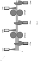
- FIG. 1 shows an illustrative example of the looper-less rolling mill arrangement 2 used in accordance with the invention.
- the looper-less roll mill arrangement 2 includes a rolling mill line 4, rolling mill stands STD13 and STD14, cameras C12o, C13o and C14o, and output lasers L12o, L13o and L140.
- the rolling mill product is moved thru various points in the mill 2 using a rolling mill line 4 that passes thru a number of rolling mill stands.
- Each rolling mill stand STD13, STD14 includes a respective camera C12o, C13o, C14o and output laser L12o, L13o, L14o.
- Each camera C12o, C13o, C14o is used as a visual tool to assess the quality of the rolling mill product, such as the height of a stock section for accurate control.
- Each laser L12o, L13o, L14o measures the true product speed of the rolling mill line 4 and compares this with the calculated speed at this point and makes the necessary speed adjustments to the rolling mill stand in question and the subsequent rolling mill stands if needed to balance the rolling process.
- the rolling mill stands are connected to a control system that allows for the speed adjustment at each rolling mill stand. Both the laser and the camera can share a common mount or enclosure.
- the individual rolling mill stands are controlled from a master speed reference.
- This speed reference takes into consideration the calculated reduction in area achieved in each rolling mill stand, the roll diameter of each rolling mill stand, and the associated gear ratio.
- the error can manifest itself due to slightly incorrect roll profiles or diameters, poor section control in the mill, or slight differences in the theoretical and actual gearbox ratios in the rolling mill stands.
- a MTC (minimum tension control) system is utilized that leverages an iterative self-learning system to match the rolling mill stand speeds. Further upstream in the rolling mill, this iterative approach is not possible as the speed error grows and the risk of a rolling mill cobble increases.
- the means for controlling this error in speed in most rolling mills in the prior art is the looper.
- the looper is effectively a mechanical piece of equipment that is controlled by a loop.
- the looper allows for a mismatch in equipment speed by giving the rolling mill product a buffer space to either grow a loop or collapse a loop to a setpoint with limits for loop growth or decay dependent upon process changes.
- the looper effectively balances any error in the rolling mill speed reference.
- a new speed reference is then sent to a control device in the mill to control the rolling speeds so as to ensure the speed of each rolling mill stand is correct relative to the one before it and/or after it.
- the speed reference is a calculated value and is subject to error.
- the invention eliminates the need for the mechanical looper and its associated control.
- the looper is replaced with a simple laser velocimetry system described herein.
- One laser is positioned in-between each individual rolling mill stand. This can include machines of multiple rolls but with one drive motor.
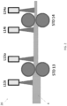
- FIG. 2 shows an illustrative example of another embodiment of the looper-less rolling mill arrangement 20 used in accordance with the invention.
- the looper-less rolling mill arrangement 20 includes a rolling mill having a line 4, roll milling stands STD13 and STD14, input lasers L13i and L14i, and output lasers L13o and L140. Note the looper-less arrangement 20 is similar to the looper-less rolling mill arrangement 2 of FIG. 1 .
- Each rolling mill stand STD13, STD14 includes a respective input laser L13i, L14i and output laser L13o, L14o.
- the input lasers L13i, L14i measure the incoming speed of the rolling mill product to its respective rolling stand STD13, STD14.
- the output lasers L13o, L14o measure the outgoing speed of the rolling mill product from its respective rolling stand STD13, STD14.
- the incoming speeds and outgoing speeds of the rolling mill product at each rolling mill stand is compared to its theoretically controlled rolling speed as well as comparing the incoming speed and outgoing speed form a previous rolling mill stand.
- the invention can allow the ring spacing at the laying head area of a rolling mill to be maintained perfectly from head to tail of a rolling mill product. Any change in product speed could be instantly adjusted using the lasers and cameras discussed herein.
- the information provided by the cameras and lasers can be used to devise an intelligent mill system that requires less mechanical equipment. This can reduce the building length and any associated costs as well as the cost of maintaining less equipment, and the product quality is improved due to the overall increase in accurate seed control of the rolling mill.
- two non-contact gauges can be utilized, one at the exit of the first rolling mill stand and one at the entry to the subsequent rolling mill stand. This ensures any effects from quenching and resistance to forward motion is accounted by the control device.
Landscapes
- Engineering & Computer Science (AREA)
- Mechanical Engineering (AREA)
- Metal Rolling (AREA)
- Control Of Metal Rolling (AREA)
- Laminated Bodies (AREA)
Description
- The invention is related to the field of long product mills, and in particular to long product mills utilizing tensionless or loop-less smart rolling or a method thereof according to the preamble of claims 1 and 9.
- Inter-stand tension is inherent in all long rolling mills. The physical manifestation of tension is the difference in speed from one rolling mill stand to the other, in theory the speed of each rolling mill stand is derived from the work being carried out, however due to differences in material spread, roll wear and stock control, the speed between two rolling mill stands in a long products mill is never 100% matched. This mismatch is called tension or compression as the material can be pushed and or pulled dependent on the error in speed between the two rolling mill stands.
- In the early part of a rolling mill, tension control is managed using a minimum control tension system (MTC). The MTC calculates the speed and torque for each rolling mill stand allowing for speed adjustments. Such a control arrangement is described by
JPS59118212A - In the later part of the rolling mill, loopers are utilized that are natural breaks in the mill rolling process. A loop is formed to give an area of float or a buffer in the continuous process between two rolling stands. This loop can be pushed or pulled as the mill speed changes. If the loop grows or shrinks out of a preset position the rolling mill stands can adjust their speeds accordingly in an attempt to maintain equilibrium.
- The theory being that with the looper in the ideal or dead band position, an error in speed between the rolling mill stands is compensated for and the process remains stable. A looper, however, never removes all tension or compression in the mill as by nature the true material speed is never known and the force of the push or pull is inherent in the material. Loopers include mechanical and electrics/automation (EA) equipment that has an added cost and they add length to the overall rolling mill further adding to the overall cost of a rolling mill line.
- According to one aspect of the invention as claimed in claim 1, there is provided a rolling mill for producing rolling mill product. The rolling mill includes a rolling mill line that moves the rolling mill product. A plurality of rolling mill stands are coupled to the rolling mill line that receives the rolling mill product and rolls the rolling mill product. A plurality of speed measuring devices that are positioned in close proximity to each rolling mill stand, where each speed measuring device measures the speed of the rolling mill product as it passes the speed measuring devices. A control device receives information associated with the speed measuring devices and adjusts the speed of the rolling mill product for any speed differential that might exist between any of the rolling mill stands, wherein the speed differential is the difference between the actual speed of the rolling mill product with a calculated speed at a point on the rolling mill line.
- According to another aspect of the invention, as claimed in claim 9, there is provided a method for producing rolling mill product in a rolling mill. The method includes providing a rolling mill line that moves the rolling mill product. Also, the method includes providing a plurality of rolling mill stands that are coupled to the rolling line that receives the rolling mill product and rolls the rolling mill product. A plurality of speed measuring devices are positioned in close proximity to each rolling mill stand, where each speed measuring device measures the speed of the rolling mill product as it passes the speed measuring devices. Furthermore, the method includes adjusting the speed of the rolling mill product for any speed differential that might exist between any of the rolling mill stands using a control device that receives information associated with the speed measuring devices, wherein the speed differential is the difference between the actual speed of the rolling mill product with a calculated speed at a point on the rolling mill line.
- These and further advantageous aspects of the claimed invention will now be described in further detail with reference to the accompanying drawings..
-
FIG. 1 is a schematic diagram illustrating the looper-less rolling mill arrangement used in accordance with the invention; and -
FIG. 2 is a schematic diagram illustrating another embodiment of the looper-less rolling mill arrangement used in accordance with the invention. - The invention describes a systematic approach that eliminates the need for a mechanical looper in a rolling mill and its associated control. The looper is replaced with a simple laser velocimetry system and/or camera arrangement where one laser is positioned in-between each individual rolling mill stand. This can include machines of multiple rolls but with one drive motor.
- In the prior art, the tension and loop control systems work from a theoretical speed calculated from a theoretical working diameter. This diameter change is dependent on the process section being rolled. Furthermore, as the material is rolled in the rolling mill, its area is reduced and passes through each subsequent rolling mill stand at higher velocities. This complicates a looper design and control as enough buffer "storage" must be accounted for each looper to effectively support and control smaller product or sections sizes.
- As an example, if a section in question is travelling at 15 m/s and the rolling stands in question have the ability to adjust at 2.5 m/s/s. Then the required loop storage for a speed differential of 3% would be 0.18m of material, from the initial start position or pass line to reach equilibrium.
- The invention eliminates the need for the complications and limitations referenced above, as the actual product speed between rolling mill stands is measured with non-contact velocimetry. In the early part of the rolling mill line, speed measurements can be utilized as the rolling mill stands are positioned close to one another as the metallurgical process in the mill does not require water-quenching and/or equalization.
-
FIG. 1 shows an illustrative example of the looper-lessrolling mill arrangement 2 used in accordance with the invention. The looper-lessroll mill arrangement 2 includes a rolling mill line 4, rolling mill stands STD13 and STD14, cameras C12o, C13o and C14o, and output lasers L12o, L13o and L140. The rolling mill product is moved thru various points in themill 2 using a rolling mill line 4 that passes thru a number of rolling mill stands. Each rolling mill stand STD13, STD14 includes a respective camera C12o, C13o, C14o and output laser L12o, L13o, L14o. - Each camera C12o, C13o, C14o is used as a visual tool to assess the quality of the rolling mill product, such as the height of a stock section for accurate control. Each laser L12o, L13o, L14o measures the true product speed of the rolling mill line 4 and compares this with the calculated speed at this point and makes the necessary speed adjustments to the rolling mill stand in question and the subsequent rolling mill stands if needed to balance the rolling process. The rolling mill stands are connected to a control system that allows for the speed adjustment at each rolling mill stand. Both the laser and the camera can share a common mount or enclosure.
- In most rolling mills, the individual rolling mill stands are controlled from a master speed reference. This speed reference takes into consideration the calculated reduction in area achieved in each rolling mill stand, the roll diameter of each rolling mill stand, and the associated gear ratio.
- The error can manifest itself due to slightly incorrect roll profiles or diameters, poor section control in the mill, or slight differences in the theoretical and actual gearbox ratios in the rolling mill stands. In the slower part of the rolling mill, a MTC (minimum tension control) system is utilized that leverages an iterative self-learning system to match the rolling mill stand speeds. Further upstream in the rolling mill, this iterative approach is not possible as the speed error grows and the risk of a rolling mill cobble increases.
- The means for controlling this error in speed in most rolling mills in the prior art is the looper. The looper is effectively a mechanical piece of equipment that is controlled by a loop. The looper allows for a mismatch in equipment speed by giving the rolling mill product a buffer space to either grow a loop or collapse a loop to a setpoint with limits for loop growth or decay dependent upon process changes. The looper effectively balances any error in the rolling mill speed reference. A new speed reference is then sent to a control device in the mill to control the rolling speeds so as to ensure the speed of each rolling mill stand is correct relative to the one before it and/or after it. As one can theorize, the speed reference is a calculated value and is subject to error.
- The invention eliminates the need for the mechanical looper and its associated control. The looper is replaced with a simple laser velocimetry system described herein. One laser is positioned in-between each individual rolling mill stand. This can include machines of multiple rolls but with one drive motor.
-
FIG. 2 shows an illustrative example of another embodiment of the looper-lessrolling mill arrangement 20 used in accordance with the invention. The looper-lessrolling mill arrangement 20 includes a rolling mill having a line 4, roll milling stands STD13 and STD14, input lasers L13i and L14i, and output lasers L13o and L140. Note thelooper-less arrangement 20 is similar to the looper-lessrolling mill arrangement 2 ofFIG. 1 . Each rolling mill stand STD13, STD14 includes a respective input laser L13i, L14i and output laser L13o, L14o. The input lasers L13i, L14i measure the incoming speed of the rolling mill product to its respective rolling stand STD13, STD14. The output lasers L13o, L14o measure the outgoing speed of the rolling mill product from its respective rolling stand STD13, STD14. - The incoming speeds and outgoing speeds of the rolling mill product at each rolling mill stand is compared to its theoretically controlled rolling speed as well as comparing the incoming speed and outgoing speed form a previous rolling mill stand.
- Using the invention and tying the actual rolling mill product speed into the control device of a rolling mill, one could further improve the control of ancillary machines, such as head and tail crop shears, or achieve shorter crop lengths thus reducing metallic yield loss.
- Moreover, the invention can allow the ring spacing at the laying head area of a rolling mill to be maintained perfectly from head to tail of a rolling mill product. Any change in product speed could be instantly adjusted using the lasers and cameras discussed herein. Moreover, the information provided by the cameras and lasers can be used to devise an intelligent mill system that requires less mechanical equipment. This can reduce the building length and any associated costs as well as the cost of maintaining less equipment, and the product quality is improved due to the overall increase in accurate seed control of the rolling mill.
- Where metallurgical processes dictate larger inter-stand distance due to the necessity to quenching and equalization, then two non-contact gauges can be utilized, one at the exit of the first rolling mill stand and one at the entry to the subsequent rolling mill stand. This ensures any effects from quenching and resistance to forward motion is accounted by the control device.
- Although the present invention has been shown and described with respect to several preferred embodiments thereof, various changes, omissions and additions to the form and detail thereof, may be made therein, without departing from the scope of the invention as defined by the appended claims.
Claims (16)
- A rolling mill for producing rolling mill product, said rolling mill comprising:a rolling mill line (4) that moves the rolling mill product;a plurality of rolling mill stands (STD13, STD14) that are coupled to the rolling mill line that receives the rolling mill product and rolls the rolling mill product;a plurality of speed measuring devices that are positioned in close proximity to each rolling mill stand, each speed measuring device measures the speed of the rolling mill product as it passes the speed measuring devices; anda control device that receives information associated with the speed measuring devices characterized in that said control device adjusts the speed of the rolling mill product for any speed differential that might exist between any of the rolling mill stands, wherein the speed differential is the difference between the actual speed of the rolling mill product with a calculated speed at a point on the rolling mill line.
- The rolling mill of claim 1, wherein the speed measuring devices comprise a laser (L12o, L13i, L13o, L14i, L14o) and a camera (C12o, C13o, C14o).
- The rolling mill of claim 2, wherein the camera (C12o, C13o, C14o) assesses the quality of the rolling mill product.
- The rolling mill of claim 3, wherein the laser (L12o, L13i, L13o, L14i, L14o) measures the actual speed of the rolling mill product.
- The rolling mill of claim 1, wherein the speed measuring devices comprise a plurality of lasers (L12o, L13i, L13o, L14i, L14o).
- The rolling mill of claim 5, wherein the lasers (L12o, L13i, L13o, L14i, L14o) are arranged such that a selective number of the lasers is associated with each rolling mill stand (STD13, STD14).
- The rolling mill of claim 6, wherein the selective number of the lasers (L12o, L13i, L13o, L14i, L14o) measure the incoming and outgoing speeds of the rolling mill product for its respective rolling mill stand (STD13, STD14).
- The rolling mill of claim 1, wherein the control device increases or decreases the rolling speed of one or more rolling mill stands (STD13, STD14) to ensure the mill speeds are equalized to stabilize the rolling mill.
- A method for producing rolling mill product in a rolling mill, said method comprising:providing a rolling mill line (4) that moves the rolling mill product;providing a plurality of rolling mill stands (STD13, STD14) that are coupled to the rolling line that receives the rolling mill product and rolls the rolling mill product;positioning in close proximity to each rolling mill stand a plurality of speed measuring devices, each speed measuring device measures the speed of the rolling mill product as it passes the speed measuring devices; and characterized byadjusting the speed of the rolling mill product for any speed differential that might exist between any of the rolling mill stands using a control device that receives information associated with the speed measuring devices, wherein the speed differential is the difference between the actual speed of the rolling mill product with a calculated speed at a point on the rolling mill line.
- The method of claim 9, wherein the speed measuring devices comprise a laser (L12o, L13i, L13o, L14i, L14o) and a camera (C12o, C13o, C14o).
- The method of claim 10, wherein the camera (C12o, C13o, C14o) assesses the quality of the rolling mill product.
- The method of claim 10 or 11, wherein the laser (L12o, L13i, L13o, L14i, L14o) measures the actual speed of the rolling mill product.
- The method of claim 9, wherein the speed measuring devices comprises a plurality of lasers (L12o, L13i, L13o, L14i, L14o).
- The method of claim 13, wherein the lasers (L12o, L13i, L13o, L14i, L14o) are arranged such that a selective number of the lasers is associated with each rolling mill stand (STD13, STD14).
- The method of claim 14, wherein the selective number of the lasers (L13i, L13o, L14i, L14o) measure the incoming and outgoing speeds of the rolling mill product for its respective rolling mill stand (STD13, STD14).
- The method of claim 9, wherein the control device increases or decreases the rolling speed of one or more rolling mill stands (STD13, STD14) to stabilize the rolling mill.
Applications Claiming Priority (2)
| Application Number | Priority Date | Filing Date | Title |
|---|---|---|---|
| US15/834,714 US20190176199A1 (en) | 2017-12-07 | 2017-12-07 | Looper-less smart rolling in long product mills |
| PCT/US2018/060668 WO2019112758A1 (en) | 2017-12-07 | 2018-11-13 | Looper-less smart rolling in long product mills |
Publications (2)
| Publication Number | Publication Date |
|---|---|
| EP3720622A1 EP3720622A1 (en) | 2020-10-14 |
| EP3720622B1 true EP3720622B1 (en) | 2023-03-22 |
Family
ID=64661454
Family Applications (1)
| Application Number | Title | Priority Date | Filing Date |
|---|---|---|---|
| EP18815849.7A Active EP3720622B1 (en) | 2017-12-07 | 2018-11-13 | Looper-less smart rolling in long product mills |
Country Status (4)
| Country | Link |
|---|---|
| US (1) | US20190176199A1 (en) |
| EP (1) | EP3720622B1 (en) |
| ES (1) | ES2946466T3 (en) |
| WO (1) | WO2019112758A1 (en) |
Family Cites Families (4)
| Publication number | Priority date | Publication date | Assignee | Title |
|---|---|---|---|---|
| JPS59118212A (en) * | 1982-12-22 | 1984-07-07 | Kawasaki Steel Corp | Control method of tension in bar steel continuous rolling mill |
| SE517670C2 (en) * | 1998-07-10 | 2002-07-02 | Abb Ab | Method and apparatus for continuous control of the intermediate voltage in a rolling mill |
| SE513922C2 (en) * | 1998-07-10 | 2000-11-27 | Abb Ab | Method and apparatus for controlling tail exit dimensions in a rolling mill |
| US9630228B2 (en) * | 2012-01-19 | 2017-04-25 | Primetals Technologies USA LLC | Dual cascade control system for a long rolling mill |
-
2017
- 2017-12-07 US US15/834,714 patent/US20190176199A1/en not_active Abandoned
-
2018
- 2018-11-13 ES ES18815849T patent/ES2946466T3/en active Active
- 2018-11-13 EP EP18815849.7A patent/EP3720622B1/en active Active
- 2018-11-13 WO PCT/US2018/060668 patent/WO2019112758A1/en not_active Ceased
Also Published As
| Publication number | Publication date |
|---|---|
| WO2019112758A1 (en) | 2019-06-13 |
| EP3720622A1 (en) | 2020-10-14 |
| ES2946466T3 (en) | 2023-07-19 |
| US20190176199A1 (en) | 2019-06-13 |
Similar Documents
| Publication | Publication Date | Title |
|---|---|---|
| CN106944479B (en) | A kind of thin strip single chassis tandem mill and implementation method | |
| CN104338753B (en) | A kind of dynamic variable specification control method of cold continuous rolling | |
| JP5960848B2 (en) | Method for controlling a production plant of two continuous strands obtained from a single billet | |
| CN104801548B (en) | Method for automatically improving per-second flow balance of strip steel in hot continuous rolling strip threading process | |
| CN103551389B (en) | Flying gauge change control method of tandem cold mill | |
| DE202014011231U1 (en) | Dynamic Reduction Displacement (DSR) system for controlling a temperature in tandem mills | |
| US9630228B2 (en) | Dual cascade control system for a long rolling mill | |
| US20190176199A1 (en) | Looper-less smart rolling in long product mills | |
| US3559431A (en) | Apparatus for stretching continuous bands | |
| CN109047340B (en) | Control method for hot rolling and finish rolling multistage threading speed | |
| CN105658347B (en) | For processing the method and roll line of stocking in roll line | |
| US3992915A (en) | Rolling mill | |
| EP2460597A1 (en) | Method for controlling a tandem mill train, control and/or regulating device for a tandem mill train, machine-readable programming code, storage medium and tandem mill train | |
| US8113026B2 (en) | Apparatus and method for reducing the section and sizing of rolling mill products for wire rod | |
| EP3713686B2 (en) | Device for controlling a stretch-reducing mill | |
| CN104148413B (en) | A kind of torque adjusting device coefficient jockey pulley control method | |
| SE444273B (en) | PROCEDURE FOR SETTING THE ROLLER WITH A ROLLER WITH MULTIPLE ROLLER | |
| JP6935588B2 (en) | How to adjust the pulling action on the bar and the corresponding device | |
| US8375760B2 (en) | Making and coiling rod and wire | |
| RU2446026C2 (en) | Method of strip tension automatic control in interstand space of hot rolling broad-strip stand | |
| CN119016515B (en) | A control method and device for dynamically adjusting the frame load of a cold rolling mill | |
| CN211870930U (en) | Textile product winding device with adjustable tension degree | |
| CN107900115A (en) | Control method for producing 3.0mm cold-rolled product | |
| Abrosimov et al. | Improving the Rolling Process Stability on a Continuous Wide-Strip Hot Rolling Mill 2000 by Improving the Operating Modes of Control Systems | |
| SU1205955A1 (en) | Method of continuous rolling of superimposed strips |
Legal Events
| Date | Code | Title | Description |
|---|---|---|---|
| STAA | Information on the status of an ep patent application or granted ep patent |
Free format text: STATUS: UNKNOWN |
|
| STAA | Information on the status of an ep patent application or granted ep patent |
Free format text: STATUS: THE INTERNATIONAL PUBLICATION HAS BEEN MADE |
|
| PUAI | Public reference made under article 153(3) epc to a published international application that has entered the european phase |
Free format text: ORIGINAL CODE: 0009012 |
|
| STAA | Information on the status of an ep patent application or granted ep patent |
Free format text: STATUS: REQUEST FOR EXAMINATION WAS MADE |
|
| 17P | Request for examination filed |
Effective date: 20200707 |
|
| AK | Designated contracting states |
Kind code of ref document: A1 Designated state(s): AL AT BE BG CH CY CZ DE DK EE ES FI FR GB GR HR HU IE IS IT LI LT LU LV MC MK MT NL NO PL PT RO RS SE SI SK SM TR |
|
| AX | Request for extension of the european patent |
Extension state: BA ME |
|
| DAV | Request for validation of the european patent (deleted) | ||
| DAX | Request for extension of the european patent (deleted) | ||
| STAA | Information on the status of an ep patent application or granted ep patent |
Free format text: STATUS: EXAMINATION IS IN PROGRESS |
|
| 17Q | First examination report despatched |
Effective date: 20220509 |
|
| GRAP | Despatch of communication of intention to grant a patent |
Free format text: ORIGINAL CODE: EPIDOSNIGR1 |
|
| STAA | Information on the status of an ep patent application or granted ep patent |
Free format text: STATUS: GRANT OF PATENT IS INTENDED |
|
| INTG | Intention to grant announced |
Effective date: 20221206 |
|
| RIN1 | Information on inventor provided before grant (corrected) |
Inventor name: RICHES, PAUL BARRY Inventor name: PALFREMAN, MATTHEW D. Inventor name: MORGAN, STEVEN |
|
| GRAS | Grant fee paid |
Free format text: ORIGINAL CODE: EPIDOSNIGR3 |
|
| GRAA | (expected) grant |
Free format text: ORIGINAL CODE: 0009210 |
|
| STAA | Information on the status of an ep patent application or granted ep patent |
Free format text: STATUS: THE PATENT HAS BEEN GRANTED |
|
| AK | Designated contracting states |
Kind code of ref document: B1 Designated state(s): AL AT BE BG CH CY CZ DE DK EE ES FI FR GB GR HR HU IE IS IT LI LT LU LV MC MK MT NL NO PL PT RO RS SE SI SK SM TR |
|
| REG | Reference to a national code |
Ref country code: GB Ref legal event code: FG4D |
|
| REG | Reference to a national code |
Ref country code: CH Ref legal event code: EP |
|
| REG | Reference to a national code |
Ref country code: DE Ref legal event code: R096 Ref document number: 602018047552 Country of ref document: DE |
|
| REG | Reference to a national code |
Ref country code: IE Ref legal event code: FG4D |
|
| REG | Reference to a national code |
Ref country code: AT Ref legal event code: REF Ref document number: 1554968 Country of ref document: AT Kind code of ref document: T Effective date: 20230415 |
|
| REG | Reference to a national code |
Ref country code: LT Ref legal event code: MG9D |
|
| REG | Reference to a national code |
Ref country code: ES Ref legal event code: FG2A Ref document number: 2946466 Country of ref document: ES Kind code of ref document: T3 Effective date: 20230719 |
|
| REG | Reference to a national code |
Ref country code: NL Ref legal event code: MP Effective date: 20230322 |
|
| PG25 | Lapsed in a contracting state [announced via postgrant information from national office to epo] |
Ref country code: RS Free format text: LAPSE BECAUSE OF FAILURE TO SUBMIT A TRANSLATION OF THE DESCRIPTION OR TO PAY THE FEE WITHIN THE PRESCRIBED TIME-LIMIT Effective date: 20230322 Ref country code: NO Free format text: LAPSE BECAUSE OF FAILURE TO SUBMIT A TRANSLATION OF THE DESCRIPTION OR TO PAY THE FEE WITHIN THE PRESCRIBED TIME-LIMIT Effective date: 20230622 Ref country code: LV Free format text: LAPSE BECAUSE OF FAILURE TO SUBMIT A TRANSLATION OF THE DESCRIPTION OR TO PAY THE FEE WITHIN THE PRESCRIBED TIME-LIMIT Effective date: 20230322 Ref country code: LT Free format text: LAPSE BECAUSE OF FAILURE TO SUBMIT A TRANSLATION OF THE DESCRIPTION OR TO PAY THE FEE WITHIN THE PRESCRIBED TIME-LIMIT Effective date: 20230322 Ref country code: HR Free format text: LAPSE BECAUSE OF FAILURE TO SUBMIT A TRANSLATION OF THE DESCRIPTION OR TO PAY THE FEE WITHIN THE PRESCRIBED TIME-LIMIT Effective date: 20230322 |
|
| REG | Reference to a national code |
Ref country code: AT Ref legal event code: MK05 Ref document number: 1554968 Country of ref document: AT Kind code of ref document: T Effective date: 20230322 |
|
| PG25 | Lapsed in a contracting state [announced via postgrant information from national office to epo] |
Ref country code: SE Free format text: LAPSE BECAUSE OF FAILURE TO SUBMIT A TRANSLATION OF THE DESCRIPTION OR TO PAY THE FEE WITHIN THE PRESCRIBED TIME-LIMIT Effective date: 20230322 Ref country code: NL Free format text: LAPSE BECAUSE OF FAILURE TO SUBMIT A TRANSLATION OF THE DESCRIPTION OR TO PAY THE FEE WITHIN THE PRESCRIBED TIME-LIMIT Effective date: 20230322 Ref country code: GR Free format text: LAPSE BECAUSE OF FAILURE TO SUBMIT A TRANSLATION OF THE DESCRIPTION OR TO PAY THE FEE WITHIN THE PRESCRIBED TIME-LIMIT Effective date: 20230623 Ref country code: FI Free format text: LAPSE BECAUSE OF FAILURE TO SUBMIT A TRANSLATION OF THE DESCRIPTION OR TO PAY THE FEE WITHIN THE PRESCRIBED TIME-LIMIT Effective date: 20230322 |
|
| PG25 | Lapsed in a contracting state [announced via postgrant information from national office to epo] |
Ref country code: SM Free format text: LAPSE BECAUSE OF FAILURE TO SUBMIT A TRANSLATION OF THE DESCRIPTION OR TO PAY THE FEE WITHIN THE PRESCRIBED TIME-LIMIT Effective date: 20230322 Ref country code: RO Free format text: LAPSE BECAUSE OF FAILURE TO SUBMIT A TRANSLATION OF THE DESCRIPTION OR TO PAY THE FEE WITHIN THE PRESCRIBED TIME-LIMIT Effective date: 20230322 Ref country code: PT Free format text: LAPSE BECAUSE OF FAILURE TO SUBMIT A TRANSLATION OF THE DESCRIPTION OR TO PAY THE FEE WITHIN THE PRESCRIBED TIME-LIMIT Effective date: 20230724 Ref country code: EE Free format text: LAPSE BECAUSE OF FAILURE TO SUBMIT A TRANSLATION OF THE DESCRIPTION OR TO PAY THE FEE WITHIN THE PRESCRIBED TIME-LIMIT Effective date: 20230322 Ref country code: AT Free format text: LAPSE BECAUSE OF FAILURE TO SUBMIT A TRANSLATION OF THE DESCRIPTION OR TO PAY THE FEE WITHIN THE PRESCRIBED TIME-LIMIT Effective date: 20230322 |
|
| PG25 | Lapsed in a contracting state [announced via postgrant information from national office to epo] |
Ref country code: SK Free format text: LAPSE BECAUSE OF FAILURE TO SUBMIT A TRANSLATION OF THE DESCRIPTION OR TO PAY THE FEE WITHIN THE PRESCRIBED TIME-LIMIT Effective date: 20230322 Ref country code: PL Free format text: LAPSE BECAUSE OF FAILURE TO SUBMIT A TRANSLATION OF THE DESCRIPTION OR TO PAY THE FEE WITHIN THE PRESCRIBED TIME-LIMIT Effective date: 20230322 Ref country code: IS Free format text: LAPSE BECAUSE OF FAILURE TO SUBMIT A TRANSLATION OF THE DESCRIPTION OR TO PAY THE FEE WITHIN THE PRESCRIBED TIME-LIMIT Effective date: 20230722 |
|
| REG | Reference to a national code |
Ref country code: DE Ref legal event code: R097 Ref document number: 602018047552 Country of ref document: DE |
|
| PLBE | No opposition filed within time limit |
Free format text: ORIGINAL CODE: 0009261 |
|
| STAA | Information on the status of an ep patent application or granted ep patent |
Free format text: STATUS: NO OPPOSITION FILED WITHIN TIME LIMIT |
|
| PG25 | Lapsed in a contracting state [announced via postgrant information from national office to epo] |
Ref country code: SI Free format text: LAPSE BECAUSE OF FAILURE TO SUBMIT A TRANSLATION OF THE DESCRIPTION OR TO PAY THE FEE WITHIN THE PRESCRIBED TIME-LIMIT Effective date: 20230322 Ref country code: DK Free format text: LAPSE BECAUSE OF FAILURE TO SUBMIT A TRANSLATION OF THE DESCRIPTION OR TO PAY THE FEE WITHIN THE PRESCRIBED TIME-LIMIT Effective date: 20230322 Ref country code: CZ Free format text: LAPSE BECAUSE OF FAILURE TO SUBMIT A TRANSLATION OF THE DESCRIPTION OR TO PAY THE FEE WITHIN THE PRESCRIBED TIME-LIMIT Effective date: 20230322 |
|
| 26N | No opposition filed |
Effective date: 20240102 |
|
| REG | Reference to a national code |
Ref country code: CH Ref legal event code: PL |
|
| PG25 | Lapsed in a contracting state [announced via postgrant information from national office to epo] |
Ref country code: MC Free format text: LAPSE BECAUSE OF FAILURE TO SUBMIT A TRANSLATION OF THE DESCRIPTION OR TO PAY THE FEE WITHIN THE PRESCRIBED TIME-LIMIT Effective date: 20230322 |
|
| PG25 | Lapsed in a contracting state [announced via postgrant information from national office to epo] |
Ref country code: LU Free format text: LAPSE BECAUSE OF NON-PAYMENT OF DUE FEES Effective date: 20231113 |
|
| PG25 | Lapsed in a contracting state [announced via postgrant information from national office to epo] |
Ref country code: CH Free format text: LAPSE BECAUSE OF NON-PAYMENT OF DUE FEES Effective date: 20231130 |
|
| GBPC | Gb: european patent ceased through non-payment of renewal fee |
Effective date: 20231113 |
|
| PG25 | Lapsed in a contracting state [announced via postgrant information from national office to epo] |
Ref country code: MC Free format text: LAPSE BECAUSE OF FAILURE TO SUBMIT A TRANSLATION OF THE DESCRIPTION OR TO PAY THE FEE WITHIN THE PRESCRIBED TIME-LIMIT Effective date: 20230322 Ref country code: LU Free format text: LAPSE BECAUSE OF NON-PAYMENT OF DUE FEES Effective date: 20231113 Ref country code: CH Free format text: LAPSE BECAUSE OF NON-PAYMENT OF DUE FEES Effective date: 20231130 |
|
| REG | Reference to a national code |
Ref country code: BE Ref legal event code: MM Effective date: 20231130 |
|
| REG | Reference to a national code |
Ref country code: IE Ref legal event code: MM4A |
|
| PG25 | Lapsed in a contracting state [announced via postgrant information from national office to epo] |
Ref country code: IE Free format text: LAPSE BECAUSE OF NON-PAYMENT OF DUE FEES Effective date: 20231113 |
|
| PG25 | Lapsed in a contracting state [announced via postgrant information from national office to epo] |
Ref country code: GB Free format text: LAPSE BECAUSE OF NON-PAYMENT OF DUE FEES Effective date: 20231113 |
|
| PG25 | Lapsed in a contracting state [announced via postgrant information from national office to epo] |
Ref country code: BE Free format text: LAPSE BECAUSE OF NON-PAYMENT OF DUE FEES Effective date: 20231130 |
|
| PG25 | Lapsed in a contracting state [announced via postgrant information from national office to epo] |
Ref country code: FR Free format text: LAPSE BECAUSE OF NON-PAYMENT OF DUE FEES Effective date: 20231130 |
|
| PG25 | Lapsed in a contracting state [announced via postgrant information from national office to epo] |
Ref country code: IE Free format text: LAPSE BECAUSE OF NON-PAYMENT OF DUE FEES Effective date: 20231113 Ref country code: GB Free format text: LAPSE BECAUSE OF NON-PAYMENT OF DUE FEES Effective date: 20231113 Ref country code: FR Free format text: LAPSE BECAUSE OF NON-PAYMENT OF DUE FEES Effective date: 20231130 Ref country code: BE Free format text: LAPSE BECAUSE OF NON-PAYMENT OF DUE FEES Effective date: 20231130 |
|
| PG25 | Lapsed in a contracting state [announced via postgrant information from national office to epo] |
Ref country code: BG Free format text: LAPSE BECAUSE OF FAILURE TO SUBMIT A TRANSLATION OF THE DESCRIPTION OR TO PAY THE FEE WITHIN THE PRESCRIBED TIME-LIMIT Effective date: 20230322 |
|
| PG25 | Lapsed in a contracting state [announced via postgrant information from national office to epo] |
Ref country code: BG Free format text: LAPSE BECAUSE OF FAILURE TO SUBMIT A TRANSLATION OF THE DESCRIPTION OR TO PAY THE FEE WITHIN THE PRESCRIBED TIME-LIMIT Effective date: 20230322 |
|
| PG25 | Lapsed in a contracting state [announced via postgrant information from national office to epo] |
Ref country code: CY Free format text: LAPSE BECAUSE OF FAILURE TO SUBMIT A TRANSLATION OF THE DESCRIPTION OR TO PAY THE FEE WITHIN THE PRESCRIBED TIME-LIMIT; INVALID AB INITIO Effective date: 20181113 |
|
| PG25 | Lapsed in a contracting state [announced via postgrant information from national office to epo] |
Ref country code: HU Free format text: LAPSE BECAUSE OF FAILURE TO SUBMIT A TRANSLATION OF THE DESCRIPTION OR TO PAY THE FEE WITHIN THE PRESCRIBED TIME-LIMIT; INVALID AB INITIO Effective date: 20181113 |
|
| PG25 | Lapsed in a contracting state [announced via postgrant information from national office to epo] |
Ref country code: TR Free format text: LAPSE BECAUSE OF FAILURE TO SUBMIT A TRANSLATION OF THE DESCRIPTION OR TO PAY THE FEE WITHIN THE PRESCRIBED TIME-LIMIT Effective date: 20230322 |
|
| PGFP | Annual fee paid to national office [announced via postgrant information from national office to epo] |
Ref country code: DE Payment date: 20251119 Year of fee payment: 8 |
|
| PGFP | Annual fee paid to national office [announced via postgrant information from national office to epo] |
Ref country code: IT Payment date: 20251125 Year of fee payment: 8 |
|
| PGFP | Annual fee paid to national office [announced via postgrant information from national office to epo] |
Ref country code: ES Payment date: 20251229 Year of fee payment: 8 |