EP3719905A1 - Redox flow battery - Google Patents
Redox flow battery Download PDFInfo
- Publication number
- EP3719905A1 EP3719905A1 EP17875070.9A EP17875070A EP3719905A1 EP 3719905 A1 EP3719905 A1 EP 3719905A1 EP 17875070 A EP17875070 A EP 17875070A EP 3719905 A1 EP3719905 A1 EP 3719905A1
- Authority
- EP
- European Patent Office
- Prior art keywords
- communicating tube
- electrolyte
- electrolytes
- tanks
- tube
- Prior art date
- Legal status (The legal status is an assumption and is not a legal conclusion. Google has not performed a legal analysis and makes no representation as to the accuracy of the status listed.)
- Granted
Links
Images

Classifications
-
- H—ELECTRICITY
- H01—ELECTRIC ELEMENTS
- H01M—PROCESSES OR MEANS, e.g. BATTERIES, FOR THE DIRECT CONVERSION OF CHEMICAL ENERGY INTO ELECTRICAL ENERGY
- H01M8/00—Fuel cells; Manufacture thereof
- H01M8/18—Regenerative fuel cells, e.g. redox flow batteries or secondary fuel cells
- H01M8/184—Regeneration by electrochemical means
- H01M8/188—Regeneration by electrochemical means by recharging of redox couples containing fluids; Redox flow type batteries
-
- H—ELECTRICITY
- H01—ELECTRIC ELEMENTS
- H01M—PROCESSES OR MEANS, e.g. BATTERIES, FOR THE DIRECT CONVERSION OF CHEMICAL ENERGY INTO ELECTRICAL ENERGY
- H01M8/00—Fuel cells; Manufacture thereof
- H01M8/04—Auxiliary arrangements, e.g. for control of pressure or for circulation of fluids
- H01M8/04082—Arrangements for control of reactant parameters, e.g. pressure or concentration
- H01M8/04186—Arrangements for control of reactant parameters, e.g. pressure or concentration of liquid-charged or electrolyte-charged reactants
-
- H—ELECTRICITY
- H01—ELECTRIC ELEMENTS
- H01M—PROCESSES OR MEANS, e.g. BATTERIES, FOR THE DIRECT CONVERSION OF CHEMICAL ENERGY INTO ELECTRICAL ENERGY
- H01M8/00—Fuel cells; Manufacture thereof
- H01M8/04—Auxiliary arrangements, e.g. for control of pressure or for circulation of fluids
- H01M8/04082—Arrangements for control of reactant parameters, e.g. pressure or concentration
- H01M8/04201—Reactant storage and supply, e.g. means for feeding, pipes
-
- H—ELECTRICITY
- H01—ELECTRIC ELEMENTS
- H01M—PROCESSES OR MEANS, e.g. BATTERIES, FOR THE DIRECT CONVERSION OF CHEMICAL ENERGY INTO ELECTRICAL ENERGY
- H01M8/00—Fuel cells; Manufacture thereof
- H01M8/04—Auxiliary arrangements, e.g. for control of pressure or for circulation of fluids
- H01M8/04276—Arrangements for managing the electrolyte stream, e.g. heat exchange
-
- H—ELECTRICITY
- H01—ELECTRIC ELEMENTS
- H01M—PROCESSES OR MEANS, e.g. BATTERIES, FOR THE DIRECT CONVERSION OF CHEMICAL ENERGY INTO ELECTRICAL ENERGY
- H01M8/00—Fuel cells; Manufacture thereof
- H01M8/04—Auxiliary arrangements, e.g. for control of pressure or for circulation of fluids
- H01M8/04298—Processes for controlling fuel cells or fuel cell systems
- H01M8/04694—Processes for controlling fuel cells or fuel cell systems characterised by variables to be controlled
- H01M8/04746—Pressure; Flow
- H01M8/04753—Pressure; Flow of fuel cell reactants
-
- Y—GENERAL TAGGING OF NEW TECHNOLOGICAL DEVELOPMENTS; GENERAL TAGGING OF CROSS-SECTIONAL TECHNOLOGIES SPANNING OVER SEVERAL SECTIONS OF THE IPC; TECHNICAL SUBJECTS COVERED BY FORMER USPC CROSS-REFERENCE ART COLLECTIONS [XRACs] AND DIGESTS
- Y02—TECHNOLOGIES OR APPLICATIONS FOR MITIGATION OR ADAPTATION AGAINST CLIMATE CHANGE
- Y02E—REDUCTION OF GREENHOUSE GAS [GHG] EMISSIONS, RELATED TO ENERGY GENERATION, TRANSMISSION OR DISTRIBUTION
- Y02E60/00—Enabling technologies; Technologies with a potential or indirect contribution to GHG emissions mitigation
- Y02E60/30—Hydrogen technology
- Y02E60/50—Fuel cells
Definitions
- the circulation of electrolyte into the battery cell 100 is made through the supply/drainage plates 210 (see the lower part of Fig. 2 ) and also through liquid supply manifolds 33 and 34 and liquid discharge manifolds 35 and 36 passing through the frame body 32 of each cell frame 3 (see the upper part of Fig. 2 ) and liquid supply slits 33s and 34s and liquid discharge slits 35s and 36s formed in the frame body 32.
- the communicating tube 40 is a tube immersed at one open end 41 thereof in the positive electrolyte 10P, stretched at an intermediate portion 43 thereof above the levels of the electrolytes 10P and 10N, and immersed at the other open end 42 thereof in the negative electrolyte 10N.
- the communicating tube 40 is configured to allow liquid-phase portions in the tanks 106 and 107 to communicate with each other.
- the communicating tube 40 is connected to the openings 64 and 74 of the tanks 106 and 107.
- the length L of the communicating tube 40 is preferably set to ensure that the flow rate of the electrolyte passing through the communicating tube 40 is above a certain level.
- the length L may be 15 m, or more preferably 10 m or less.
- the communicating tube 40 may be bent into a J shape at both end portions thereof to allow the open ends 41 and 42 to face upward. In this case, gas bubbles are not easily drawn in through the open ends 41 and 42, and this makes it easier to maintain the siphon state.
- the redox flow battery according to the embodiment can be used for load leveling, compensation for instantaneous voltage drop, emergency power supply, and smoothing of the output of natural energy-based power generation (e.g., solar or wind power generation) which has been introduced at a large scale.
- natural energy-based power generation e.g., solar or wind power generation
Landscapes
- Life Sciences & Earth Sciences (AREA)
- Engineering & Computer Science (AREA)
- Manufacturing & Machinery (AREA)
- Sustainable Development (AREA)
- Sustainable Energy (AREA)
- Chemical & Material Sciences (AREA)
- Chemical Kinetics & Catalysis (AREA)
- Electrochemistry (AREA)
- General Chemical & Material Sciences (AREA)
- Fuel Cell (AREA)
- Inert Electrodes (AREA)
Abstract
Description
- The present invention relates to a redox flow battery.
- As a large-capacity storage battery, a redox flow battery (which may hereinafter be referred to as "RF battery") is known, which performs charge and discharge by circulating positive and negative electrolytes through a battery cell (see, e.g.,
Patent Literatures 1 and 2). The RF battery includes the battery cell, a positive electrolyte tank and a negative electrolyte tank configured to store therein a positive electrolyte and a negative electrolyte, respectively, and a positive electrolyte circulation path and a negative electrolyte circulation path each configured to allow a corresponding one of the electrolytes to circulate between a corresponding one of the tanks and the battery cell.Patent Literatures -
- PTL 1: Japanese Unexamined Patent Application Publication No.
2013-25964 - PTL 2: Japanese Unexamined Patent Application Publication No.
2013-37814 - A redox flow battery of the present disclosure includes a battery cell; a positive electrolyte tank and a negative electrolyte tank configured to store therein a positive electrolyte and a negative electrolyte, respectively; a positive electrolyte circulation path and a negative electrolyte circulation path each configured to allow a corresponding one of the electrolytes to circulate between a corresponding one of the tanks and the battery cell; and a communicating tube including a tube immersed at one open end thereof in the positive electrolyte, stretched at an intermediate portion thereof above levels of both the electrolytes, and immersed at the other open end thereof in the negative electrolyte. Brief Description of Drawings
-
- [
Fig. 1] Figure 1 is a schematic diagram of a redox flow battery according to an embodiment. - [
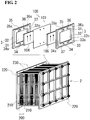
Fig. 2] Figure 2 is a schematic diagram of a cell stack. - [
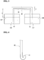
Fig. 3] Figure 3 illustrates dimensions of a communicating tube included in the redox flow battery according to the embodiment. - [
Fig. 4] Figure 4 illustrates a modified open end of the communicating tube included in the redox flow battery according to the embodiment. - [
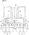
Fig. 5] Figure 5 is a schematic diagram of a redox flow battery according to a first modification. - [
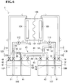
Fig. 6] Figure 6 is a schematic diagram of a redox flow battery according to a second modification. - When charge and discharge cycles are repeated during operation of a redox flow battery (RF battery), a phenomenon called "electrolyte crossover" may occur, in which positive and negative electrolytes are each transferred from one side to the other through a membrane interposed between a positive electrode and a negative electrode inside a battery cell. This may create a difference between the volumes of the electrolytes in a positive electrolyte tank and a negative electrolyte tank and lead to reduced battery capacity (discharge capacity).
- As a solution to such problems associated with the electrolyte crossover,
Patent Literatures Patent Literatures - Accordingly, the present disclosure aims to provide a redox flow battery that is capable not only of adjusting the volumes of the electrolytes in the positive electrolyte tank and the negative electrolyte tank, but also of preventing each electrolyte from flowing out of the tank.
- The present disclosure provides a redox flow battery that is capable not only of adjusting the volumes of the electrolytes in the positive electrolyte tank and the negative electrolyte tank, but also of preventing each electrolyte from flowing out of the tank.
- First, aspects of an embodiment of the invention of the present application will be listed.
- (1) A redox flow battery according to an aspect of the invention of the present application includes a battery cell; a positive electrolyte tank and a negative electrolyte tank configured to store therein a positive electrolyte and a negative electrolyte, respectively; a positive electrolyte circulation path and a negative electrolyte circulation path each configured to allow a corresponding one of the electrolytes to circulate between a corresponding one of the tanks and the battery cell; and a communicating tube including a tube immersed at one open end thereof in the positive electrolyte, stretched at an intermediate portion thereof above levels of both the electrolytes, and immersed at the other open end thereof in the negative electrolyte.
In the redox flow battery described above, the one and other open ends of the communicating tube are immersed in the positive electrolyte and the negative electrolyte, and the intermediate portion of the communicating tube is stretched above the levels of both the electrolytes. The communicating tube becomes a siphon by being filled with electrolyte. Then, when a difference occurs between the volumes of the electrolytes in the tanks, the levels of the electrolytes are adjusted to the same height through the communicating tube using the siphon principle. The volumes of the electrolytes are thus automatically adjusted to maintain the levels of the electrolytes in the tanks. If the communicating tube is broken, the resulting entry of air into the communicating tube terminates the siphon. As described above, the intermediate portion of the communicating tube is disposed above the levels of both the electrolytes. Therefore, even in the event of breakage, the electrolyte in the communicating tube is returned to either of the tanks by termination of the siphon. That is, even if the communicating tube is broken, the electrolyte in the communicating tube is prevented from flowing out of the tank. The redox flow battery described above is thus capable not only of adjusting the volumes of the electrolytes in the positive electrolyte tank and the negative electrolyte tank, but also of preventing each electrolyte from flowing out of the tank. - (2) Another aspect of the redox flow battery may include an introducing tube configured to connect at least one of the positive electrolyte circulation path and the negative electrolyte circulation path to the communicating tube, and an open-close valve configured to open and close the introducing tube.
To serve as a siphon, the communicating tube needs to be filled with electrolyte. In this aspect of the redox flow battery, which includes the introducing tube, the electrolyte is introduced through the introducing tube into the communicating tube when the redox flow battery starts, and this allows the communicating tube to be filled with the electrolyte. Also, with the open-close valve, a siphon can be created when the open-close valve closes the introducing tube to block the flow between the circulation path and the communicating tube, with the communicating tube being filled with the electrolyte. - (3) In another aspect of the redox flow battery, the open ends of the communicating tube may each be located on a bottom side in a corresponding one of the tanks.
Entry of a gas into the communicating tube may terminate the siphon. Gas bubbles may be produced in the vicinity of the surface of the electrolyte in each tank. Therefore, if an open end of the communicating tube is located near the surface of the electrolyte in the tank, gas bubbles are easily drawn in through the open end. In this aspect of the redox flow battery, where each open end of the communicating tube is located on the bottom side in the tank, gas bubbles are not easily drawn in through the open end. This makes it easier to keep the communicating tube in a siphon state. - (4) In another aspect of the redox flow battery, the open ends of the communicating tube may be formed to face upward.
In this aspect of the redox flow battery, where the open ends of the communicating tube are formed to face upward, gas bubbles are not easily drawn in through the open ends. This also makes it easier to keep the communicating tube in a siphon state. - (5) In another aspect of the redox flow battery, the communicating tube may be provided with a flow control valve.
In this aspect of the redox flow battery, where the communicating tube is provided with a flow control valve, it is possible to control, with the flow control valve, the flow rate (or the amount of transfer) of the electrolyte passing through the communicating tube when the volumes of the electrolytes in the tanks are adjusted through the communicating tube using the siphon principle. - (6) Another aspect of the redox flow battery may include a gas vent pipe configured to allow gas bubbles to escape from inside the communicating tube, and the gas vent pipe may be connected at one end thereof to the communicating tube and connected at the other end thereof to at least one of the positive electrolyte circulation path and the negative electrolyte circulation path.
- In this aspect of the redox flow battery, which includes the gas vent pipe, gas bubbles accumulated in the communicating tube can be discharged through the gas vent pipe to the circulation path. This makes it possible to keep the communicating tube in a siphon state.
- Examples of a redox flow battery (RF battery) according to an embodiment of the invention of the present application will now be described with reference to the drawings. The same reference numerals in the drawings denote the same or corresponding parts. The invention of the present application is not limited to the examples described below, and is defined by the appended claims. All changes that fall within meanings and scopes equivalent to the claims are therefore intended to be embraced by the claims.
- An RF battery according to the embodiment is typically connected through an AC/DC converter to an electric system and performs charge and discharge. The charge and discharge process involves using a positive electrolyte and a negative electrolyte each containing, as active materials, metal ions whose valences are changed by oxidation-reduction. The charge and discharge process is performed using a difference between the oxidation-reduction potential of the ions contained in the positive electrolyte and the oxidation-reduction potential of the ions contained in the negative electrolyte.
- An
RF battery 1 according to the embodiment will now be described with reference toFigs. 1 and2 . As illustrated inFig. 1 , theRF battery 1 of the embodiment includes abattery cell 100, apositive electrolyte tank 106 and anegative electrolyte tank 107, and a positiveelectrolyte circulation path 120 and a negativeelectrolyte circulation path 130. A feature of theRF battery 1 is that it includes a communicatingtube 40 for an adjustment which is made using the siphon principle such thatelectrolytes positive electrolyte tank 106 and thenegative electrolyte tank 107, respectively, have the same level. Hereinafter, the configuration of theRF battery 1 will be described in detail. - As illustrated in
Fig. 1 , thebattery cell 100 includes apositive electrode 104, anegative electrode 105, and amembrane 101 interposed between theelectrodes positive electrode cell 102 and anegative electrode cell 103 are formed with themembrane 101 therebetween. Themembrane 101 is, for example, an ion-exchange membrane that allows hydrogen ions to pass therethrough. The battery cell 100 (i.e., thepositive electrode cell 102 and the negative electrode cell 103) has the positiveelectrolyte circulation path 120 and the negativeelectrolyte circulation path 130 connected thereto, and allows thepositive electrolyte 10P and thenegative electrolyte 10N to circulate therethrough. Theelectrolytes electrolytes - The
battery cell 100 may be configured either as a single cell including onebattery cell 100, or as a multicell including a plurality ofbattery cells 100. In the case of a multicell, a structure called a cell stack 2 (seeFig. 2 ) is used, which is formed by stacking a plurality ofbattery cells 100. Thecell stack 2 includes asubstack 200 sandwiched on both sides by twoend plates 220, which are fastened with a fastening mechanism 230 (see the lower part ofFig. 2). Figure 2 illustrates a structure including a plurality ofsubstacks 200. Thesubstacks 200 are each formed by sequentially stacking acell frame 3, thepositive electrode 104, themembrane 101, and thenegative electrode 105 in layers (see the upper part ofFig. 2 ) and sandwiching the resulting layered body between supply/drainage plates 210 on both sides. The number ofbattery cells 100 stacked in layers to form thecell stack 2 can be appropriately determined. - As illustrated in the upper part of
Fig. 2 , eachcell frame 3 includes abipolar plate 31 disposed between thepositive electrode 104 and thenegative electrode 105, and aframe body 32 disposed around thebipolar plate 31. Thepositive electrode 104 is disposed on one side of thebipolar plate 31, and thenegative electrode 105 is disposed on the other side of thebipolar plate 31. Thebipolar plate 31 is disposed inside theframe body 32, and a recessed portion 32o is defined by thebipolar plate 31 and theframe body 32. The recessed portion 32o is provided on each side of thebipolar plate 31. Thepositive electrode 104 and thenegative electrode 105 are housed in the respective recessed portions 32o, with thebipolar plate 31 interposed therebetween, and a first side of theframe body 32 of eachcell frame 3 and a second side of theframe body 32 of anadjacent cell frame 3 are joined opposite each other. In the substack 200 (cell stack 2), thepositive electrode 104 and thenegative electrode 105, with themembrane 101 therebetween, are arranged between thebipolar plates 31 of adjacent cell frames 3 to form onebattery cell 100. To prevent leakage of electrolyte, theframe bodies 32 of adjacent cell frames 3 are each provided with anannular sealing member 37, such as an O ring or flat gasket, therebetween. - For example, the
bipolar plate 31 is made of plastic carbon, and theframe body 32 is made of plastic, such as vinyl chloride resin (PVC), polypropylene, polyethylene, fluorine resin, or epoxy resin. In this example, eachcell frame 3 includes thebipolar plate 31 and theframe body 32 therearound that are integrally formed, for example, by injection molding. - The circulation of electrolyte into the
battery cell 100 is made through the supply/drainage plates 210 (see the lower part ofFig. 2 ) and also throughliquid supply manifolds liquid discharge manifolds frame body 32 of each cell frame 3 (see the upper part ofFig. 2 ) andliquid supply slits frame body 32. In the case of the cell frame 3 (frame body 32) of this example, the positive electrolyte is supplied from theliquid supply manifold 33 in the lower part of theframe body 32, through theliquid supply slit 33s on the first side of theframe body 32, to thepositive electrode 104, and then discharged through the liquid discharge slit 35s in the upper part of theframe body 32 to theliquid discharge manifold 35. Similarly, the negative electrolyte is supplied from theliquid supply manifold 34 in the lower part of theframe body 32, through theliquid supply slit 34s on the second side of theframe body 32, to thenegative electrode 105, and then discharged through the liquid discharge slit 36s in the upper part of theframe body 32 to theliquid discharge manifold 36. A flow-guiding portion (not shown) may be formed along the lower and upper inner edges of theframe body 32 having thebipolar plate 31 therein. The flow-guiding portions have the function of diffusing the electrolytes supplied through theliquid supply slits electrodes electrodes - As illustrated in
Fig. 1 , thepositive electrolyte tank 106 and thenegative electrolyte tank 107 store therein thepositive electrolyte 10P and thenegative electrolyte 10N, respectively. Thetanks tanks 106 and 107 (i.e., upper part above the level of each of theelectrolytes positive electrolyte tank 106 has anoutlet 61 and aninlet 62 connected to asupply pipe 108 and areturn pipe 110, respectively, of the positiveelectrolyte circulation path 120. Thenegative electrolyte tank 107 has anoutlet 71 and theinlet 72 connected to asupply pipe 109 and areturn pipe 111, respectively, of the negativeelectrolyte circulation path 130. In this example, theoutlets inlets electrolytes tanks tanks outlet 61 and theinlet 62 are each provided with an open-close valve 66, and theoutlet 71 and theinlet 72 are each provided with an open-close valve 76. - The
tanks openings tube 40 is connected. Theopenings electrolytes tanks openings tanks openings close valves - As illustrated in
Fig. 1 , the positiveelectrolyte circulation path 120 connects thepositive electrolyte tank 106 to thebattery cell 100, whereas the negativeelectrolyte circulation path 130 connects thenegative electrolyte tank 107 to thebattery cell 100, thereby allowing theelectrolytes tanks battery cell 100. The positiveelectrolyte circulation path 120 includes thesupply pipe 108 configured to supply thepositive electrolyte 10P from thepositive electrolyte tank 106 to thepositive electrode cell 102, and thereturn pipe 110 configured to return thepositive electrolyte 10P from thepositive electrode cell 102 to thepositive electrolyte tank 106. The negativeelectrolyte circulation path 130 includes thesupply pipe 109 configured to supply thenegative electrolyte 10N from thenegative electrolyte tank 107 to thenegative electrode cell 103, and thereturn pipe 111 configured to return thenegative electrolyte 10N from thenegative electrode cell 103 to thenegative electrolyte tank 107. Thesupply pipes circulation paths outlets tanks return pipes circulation paths inlets tanks - End portions of the
respective supply pipes outlets tanks electrolytes tanks supply pipes electrolytes supply pipes tanks electrolyte tank tank electrolyte - The
supply pipes pumps electrolytes tanks pumps electrolytes positive electrode cell 102 and the negative electrode cell 103). In standby mode where neither charge nor discharge takes place, thepumps electrolytes - As illustrated in
Fig. 1 , the communicatingtube 40 is a tube immersed at oneopen end 41 thereof in thepositive electrolyte 10P, stretched at anintermediate portion 43 thereof above the levels of theelectrolytes open end 42 thereof in thenegative electrolyte 10N. The communicatingtube 40 is configured to allow liquid-phase portions in thetanks tube 40 is connected to theopenings tanks tube 40 is inserted at both end portions thereof through theopenings tanks tanks electrolytes tanks intermediate portion 43 is placed above thetanks tube 40 are each located on the bottom side in a corresponding one of thetanks - The communicating
tube 40 becomes a siphon by being filled with electrolyte. Thus, when a difference occurs between the volumes of theelectrolytes tanks electrolytes intermediate portion 43 in particular) is made of a transparent material, it is possible to visually recognize from the outside that the communicatingtube 40 is filled with electrolyte. Theintermediate portion 43 may have a window at the top (or highest portion) thereof, and the window may be made of a transparent material. Examples of the transparent material include transparent resin, such as vinyl chloride resin, and glass. - The communicating
tube 40 may be appropriately designed to satisfy the siphon principle. Dimensions of the communicating tube will now be described with reference primarily toFig. 3 . - If a height H from the level of the
electrolytes tanks tube 40 is too high, the transfer of electrolyte based on the siphon principle fails. The maximum height Hmax that satisfies the siphon principle is determined by the following equation:
- When the pressure P0 is equal to the atmospheric pressure (1.013 × 10⁵ N/m2) and the electrolyte density ρ is 1400 kg/m3, then Hmax is 7.38 m. Therefore, the installation level of the intermediate portion 43 (corresponding to the height H) is less than 7.38 m from the level of the
electrolytes tanks - If a length L of the communicating
tube 40 is too long, the resulting increase in frictional resistance in the communicatingtube 40 leads to an increased flow friction loss and lowers the flow rate of the electrolyte passing through the communicatingtube 40. This means that it takes time to adjust the electrolyte levels. The adjustment of the electrolyte levels is preferably completed within 10 minutes (or 600 seconds). Therefore, the length L of the communicatingtube 40 is preferably set to ensure that the flow rate of the electrolyte passing through the communicatingtube 40 is above a certain level. For example, the length L may be 15 m, or more preferably 10 m or less. - An inside diameter d of the communicating
tube 40 may also be appropriately set. For example, the inside diameter d may range from 10 mm to 150 mm, or more preferably from 20 mm to 100 mm. The flow friction loss varies depending also on the inside diameter d of the communicatingtube 40. That is, the smaller the inside diameter d, the greater the flow friction loss. Therefore, it is preferable to appropriately set the length L of the communicatingtube 40 in accordance with the inside diameter d. Specifically, it is preferable to set the length L of the communicatingtube 40 such that when a difference occurs between the volumes of theelectrolytes tanks electrolytes tube 40 may be less than or equal to 100 times the inside diameter d (L ≤ 100d). Specifically, the length L may be 10 m or less if the inside diameter d is 100 mm, L may be 4.5 m or less if d is 50 mm, and L may be 1.7 m or less if d is 20 mm. - The
RF battery 1 illustrated inFig. 1 includes an introducingtube 50 configured to connect the positiveelectrolyte circulation path 120 to the communicatingtube 40, and an open-close valve 51 configured to open and close the introducingtube 50. In this example, the introducingtube 50 is connected at one end thereof in such a manner as to branch off thesupply pipe 108 of the positiveelectrolyte circulation path 120 and is connected at the other end thereof to theintermediate portion 43 of the communicatingtube 40. Also, in this example, thesupply pipe 108 has an open-close valve 69 downstream of its connection with the introducing tube 50 (i.e., located closer to thebattery cell 100 than the connection is). - The introducing
tube 50 and the open-close valve 51 are used to form a siphon, when theRF battery 1 starts, by filling the communicatingtube 40 with electrolyte. Specifically, when theRF battery 1 starts, the open-close valve 51 is opened to start thepump 112, with thesupply pipe 108 and the communicatingtube 40 communicating with each other through the introducingtube 50, and circulate thepositive electrolyte 10P through the communicatingtube 40. This makes it possible to introduce thepositive electrolyte 10P into the communicatingtube 40 and fill the communicatingtube 40 with the electrolyte. Then, with the communicatingtube 40 being filled with the electrolyte, the open-close valve 51 closes the introducingtube 50 to block the flow between thesupply pipe 108 and the communicatingtube 40. This creates a liquid-tight state in the communicatingtube 40 and thereby forms a siphon. After theRF battery 1 starts, the open-close valve 51 is always in a closed state during the operation. - When, for example, the communicating
tube 40 is removed from thetanks RF battery 1, thepump 112 is stopped and the open-close valve 51 is opened. This terminates the siphon, causes the electrolyte in the communicatingtube 40 to return to thetanks tube 40 is removed from thetanks close valves tanks openings electrolytes - Although the introducing
tube 50 is connected and attached to the positive electrolyte circulation path 120 (supply pipe 108) in this example, the introducingtube 50 may be attached to the negative electrolyte circulation path 130 (supply pipe 109) or may be attached to both thecirculation paths - The
RF battery 1 illustrated inFig. 1 includes a gas-phase communicating tube 45 that allows the gas-phase portions in thetanks phase communicating tube 45, it is possible to equalize pressures in thetanks phase communicating tube 45 is stretched over thetanks phase communicating tube 45 is connected toopenings tanks openings close valves - The
RF battery 1 according to the embodiment described above has the following operational advantages. - With the communicating
tube 40, when a difference occurs between the volumes of theelectrolytes tanks RF battery 1, the levels of theelectrolytes tube 40 using the siphon principle. As described above, theintermediate portion 43 of the communicatingtube 40 is disposed above the levels of theelectrolytes tube 40 is broken, the electrolyte in the communicatingtube 40 is returned to either of thetanks tube 40, it is possible to prevent the electrolyte in the communicatingtube 40 from flowing out of thetanks openings tanks tube 40 is connected are located above the levels of theelectrolytes electrolytes openings electrolytes positive electrolyte tank 106 and thenegative electrolyte tank 107 while automatically adjusting the volumes of theelectrolytes tanks - With the introducing
tube 50 and the open-close valve 51, a siphon can be created by filling the communicatingtube 40 with electrolyte when theRF battery 1 starts. - Since the open ends 41 and 42 of the communicating
tube 40 are located on the bottom side in thetanks tube 40 in a siphon state. - As illustrated in
Fig. 4 , the communicatingtube 40 may be bent into a J shape at both end portions thereof to allow the open ends 41 and 42 to face upward. In this case, gas bubbles are not easily drawn in through the open ends 41 and 42, and this makes it easier to maintain the siphon state. - Modifications of the
RF battery 1 according to the aforementioned embodiment will now be described with reference toFigs. 5 and6 . - The
RF battery 1 according to a first modification illustrated inFig. 5 differs from the aforementioned embodiment illustrated inFig. 1 in that the communicatingtube 40 is provided with aflow control valve 44. Other configurations of the first modification are the same as those of the aforementioned embodiment. - The
flow control valve 44 is disposed in the communicatingtube 40 and configured to control the flow rate of the electrolyte passing through the communicatingtube 40. In this example, as illustrated inFig. 5 , theflow control valve 44 is disposed in theintermediate portion 43 of the communicatingtube 40. When, in theRF battery 1 of the first modification, the volumes of theelectrolytes tanks tube 40, the flow rate (or the amount of transfer) of the electrolyte can be controlled by theflow control valve 44. In some cases, the transfer of the electrolyte may be stopped by closing theflow control valve 44. In this example, theflow control valve 44 is a motor-operated valve. - The
RF battery 1 according to a second modification illustrated inFig. 6 differs from the aforementioned embodiment illustrated inFig. 1 in that it includes agas vent pipe 55 for allowing gas bubbles to escape from inside the communicatingtube 40. Other configurations of the second modification are the same as those of the aforementioned embodiment. - The
gas vent pipe 55 is used to vent, from the communicatingtube 40, gas bubbles accidentally drawn into the communicatingtube 40. Thegas vent pipe 55 is connected at one end thereof to the communicatingtube 40 and connected at the other end thereof to at least one of the positiveelectrolyte circulation path 120 and the negativeelectrolyte circulation path 130. In this example, as illustrated inFig. 6 , thegas vent pipe 55 is connected at one end thereof to theintermediate portion 43 in such a manner as to branch off the communicatingtube 40 and connected at the other end thereof to thesupply pipe 109 of the negativeelectrolyte circulation path 130 in such a manner as to join thesupply pipe 109. More specifically, thegas vent pipe 55 is connected at one end thereof to the top of theintermediate portion 43 and connected at the other end thereof to thesupply pipe 109 at a location upstream of thepump 113 in the supply pipe 109 (i.e., closer to thetank 107 than thepump 113 is). - The
gas vent pipe 55 is provided with acheck valve 56. Thecheck valve 56 is disposed in thegas vent pipe 55 and configured to block the circulation from the negative electrolyte circulation path 130 (supply pipe 109) to the communicatingtube 40. Additionally, in this example, an open-close valve 57 is provided downstream of the check valve 56 (i.e., closer to thesupply pipe 109 than thecheck valve 56 is). The open-close valve 57 is in an open state when gas bubbles are to be removed from the communicatingtube 40, and is in a closed state when there is no need to remove gas bubbles from the communicatingtube 40. - In the
RF battery 1 of the second modification, if gas bubbles are accidentally drawn into the communicatingtube 40, the gas bubbles accumulated in the communicatingtube 40 can be vented through thegas vent pipe 55 to the negative electrolyte circulation path 130 (supply pipe 109) using suction by thepump 113. This allows the communicatingtube 40 to be kept in a siphon state. With thegas vent pipe 55 having thecheck valve 56, even when thepump 113 is stopped and thesupply pipe 109 is emptied, the entry of gas from thesupply pipe 109 into the communicatingtube 40 can be blocked. Therefore, even when thepump 113 is stopped, the communicatingtube 40 is kept in a siphon state and the electrolyte in the communicatingtube 40 is not returned into either of thetanks - Additionally, by adjusting the degree of opening of the open-
close valve 57, it is possible to control the flow rate of the electrolyte passing through thegas vent pipe 55 and prevent the electrolyte from accidentally flowing out of the communicatingtube 40 into thesupply pipe 109. Specifically, suction by thepump 113 causes the electrolyte to be fed little by little through thegas vent pipe 55 and the communicatingtube 40 to thesupply pipe 109, so that gas bubbles accumulated in the communicatingtube 40 are efficiently removed. When the communicatingtube 40 is removed, for example, for maintenance of theRF battery 1, the entry of air into thesupply pipe 109 is prevented by closing the open-close valve 57. - The redox flow battery according to the embodiment can be used for load leveling, compensation for instantaneous voltage drop, emergency power supply, and smoothing of the output of natural energy-based power generation (e.g., solar or wind power generation) which has been introduced at a large scale.
-
- 1:
- redox flow battery (RF battery)
- 2:
- cell stack
- 3:
- cell frame
- 31:
- bipolar plate
- 32:
- frame body
- 32o:
- recessed portion
- 33, 34:
- liquid supply manifold
- 35, 36:
- liquid discharge manifold
- 33s, 34s:
- liquid supply slit
- 35s, 36s:
- liquid discharge slit
- 37:
- sealing member
- 40:
- communicating tube
- 41, 42:
- open end
- 43:
- intermediate portion
- 44:
- flow control valve
- 45:
- gas-phase communicating tube
- 50:
- introducing tube
- 51:
- open-close valve
- 55:
- gas vent pipe
- 56:
- check valve
- 57:
- open-close valve
- 61, 71:
- outlet
- 62, 72:
- inlet
- 64, 74:
- opening
- 65, 75:
- opening
- 66, 67, 68, 69, 76, 77, 78:
- open-close valve
- 81, 91:
- open end
- 100:
- battery cell
- 101:
- membrane
- 102:
- positive electrode cell
- 103:
- negative electrode cell
- 104:
- positive electrode
- 105:
- negative electrode
- 106:
- positive electrolyte tank
- 107:
- negative electrolyte tank
- 108, 109:
- supply pipe
- 110, 111:
- return pipe
- 112, 113:
- pump
- 120:
- positive electrolyte circulation path
- 130:
- negative electrolyte circulation path
- 10P:
- positive electrolyte
- 10N:
- negative electrolyte
- 200:
- substack
- 210:
- supply/drainage plate
- 220:
- end plate
- 230:
- fastening mechanism
Claims (6)
- A redox flow battery comprising:a battery cell;a positive electrolyte tank and a negative electrolyte tank configured to store therein a positive electrolyte and a negative electrolyte, respectively;a positive electrolyte circulation path and a negative electrolyte circulation path each configured to allow a corresponding one of the electrolytes to circulate between a corresponding one of the tanks and the battery cell; anda communicating tube including a tube immersed at one open end thereof in the positive electrolyte, stretched at an intermediate portion thereof above levels of both the electrolytes, and immersed at the other open end thereof in the negative electrolyte.
- The redox flow battery according to Claim 1, further comprising:an introducing tube configured to connect at least one of the positive electrolyte circulation path and the negative electrolyte circulation path to the communicating tube; andan open-close valve configured to open and close the introducing tube.
- The redox flow battery according to Claim 1 or 2, wherein the open ends of the communicating tube are each located on a bottom side in a corresponding one of the tanks.
- The redox flow battery according to any one of Claims 1 to 3, wherein the open ends of the communicating tube are formed to face upward.
- The redox flow battery according to any one of Claims 1 to 4, wherein the communicating tube is provided with a flow control valve.
- The redox flow battery according to any one of Claims 1 to 5, further comprising a gas vent pipe configured to allow gas bubbles to escape from inside the communicating tube,
wherein the gas vent pipe is connected at one end thereof to the communicating tube and connected at the other end thereof to at least one of the positive electrolyte circulation path and the negative electrolyte circulation path.
Applications Claiming Priority (1)
| Application Number | Priority Date | Filing Date | Title |
|---|---|---|---|
| PCT/JP2017/042652 WO2019106723A1 (en) | 2017-11-28 | 2017-11-28 | Redox flow battery |
Publications (3)
| Publication Number | Publication Date |
|---|---|
| EP3719905A1 true EP3719905A1 (en) | 2020-10-07 |
| EP3719905A4 EP3719905A4 (en) | 2020-12-23 |
| EP3719905B1 EP3719905B1 (en) | 2025-08-27 |
Family
ID=66665439
Family Applications (1)
| Application Number | Title | Priority Date | Filing Date |
|---|---|---|---|
| EP17875070.9A Active EP3719905B1 (en) | 2017-11-28 | 2017-11-28 | Redox flow battery |
Country Status (7)
| Country | Link |
|---|---|
| US (2) | US11081708B2 (en) |
| EP (1) | EP3719905B1 (en) |
| JP (1) | JP6931467B2 (en) |
| KR (1) | KR102381015B1 (en) |
| CN (1) | CN110100342A (en) |
| TW (1) | TWI788429B (en) |
| WO (1) | WO2019106723A1 (en) |
Cited By (1)
| Publication number | Priority date | Publication date | Assignee | Title |
|---|---|---|---|---|
| WO2026163160A1 (en) * | 2025-01-31 | 2026-08-06 | Invinity Energy Systems (Canada) Corporation | Improved tank assembly for a redox flow battery system |
Families Citing this family (7)
| Publication number | Priority date | Publication date | Assignee | Title |
|---|---|---|---|---|
| CN113439359B (en) * | 2019-02-27 | 2024-03-15 | 住友电气工业株式会社 | Redox flow battery |
| US11539061B2 (en) * | 2019-04-12 | 2022-12-27 | Raytheon Technologies Corporation | Cell for electrochemically determining active species concentrations in redox flow batteries |
| JP7017251B2 (en) * | 2019-07-04 | 2022-02-08 | 株式会社岐阜多田精機 | Redox flow battery |
| US11923583B2 (en) * | 2021-11-08 | 2024-03-05 | Rtx Corporation | Condensation-based redox flow battery rebalancing |
| CN119585899A (en) * | 2022-08-04 | 2025-03-07 | 住友电气工业株式会社 | Redox flow battery |
| KR102769322B1 (en) * | 2022-09-07 | 2025-02-18 | 서울과학기술대학교 산학협력단 | Redox flow battery system |
| KR102798928B1 (en) * | 2023-12-01 | 2025-04-23 | 주식회사 에이치투 | Electrolyte Antioxidant System For Redox Flow battery |
Family Cites Families (23)
| Publication number | Priority date | Publication date | Assignee | Title |
|---|---|---|---|---|
| JPH04124754A (en) * | 1990-09-14 | 1992-04-24 | Nec Corp | Communication message buffer controller |
| JP2528100Y2 (en) * | 1991-04-26 | 1997-03-05 | 住友電気工業株式会社 | Electrolyte flow battery |
| JP4155745B2 (en) * | 2002-02-27 | 2008-09-24 | 住友電気工業株式会社 | Operating method of redox flow battery |
| JP2003303611A (en) * | 2002-04-10 | 2003-10-24 | Sumitomo Electric Ind Ltd | How to operate a redox flow battery |
| JP5027384B2 (en) * | 2004-11-19 | 2012-09-19 | 関西電力株式会社 | Redox flow battery and operation method thereof |
| US7517608B2 (en) * | 2007-03-09 | 2009-04-14 | Vrb Power Systems Inc. | Inherently safe redox flow battery storage system |
| CN101463841A (en) * | 2008-03-17 | 2009-06-24 | 肖光正 | Negative-pressure siphon device of open container |
| CN102055000B (en) * | 2009-10-29 | 2015-04-22 | 北京普能世纪科技有限公司 | Redox flow battery and method for enabling battery to operate continuously for long time |
| JP5007849B1 (en) * | 2011-03-25 | 2012-08-22 | 住友電気工業株式会社 | Redox flow battery and operation method thereof |
| CN102434500A (en) * | 2011-05-05 | 2012-05-02 | 肖光正 | Water-pumping and siphoning dual-purpose pump pipe |
| EP2725648B1 (en) * | 2011-06-27 | 2018-06-13 | Sumitomo Electric Industries, Ltd. | Redox flow battery |
| JP5769071B2 (en) * | 2011-06-27 | 2015-08-26 | 住友電気工業株式会社 | Redox flow battery |
| JP2013025964A (en) | 2011-07-19 | 2013-02-04 | Sumitomo Electric Ind Ltd | Electrolyte circulation cell |
| JP2013037814A (en) | 2011-08-04 | 2013-02-21 | Sumitomo Electric Ind Ltd | Electrolyte circulation battery |
| KR101491300B1 (en) * | 2012-08-21 | 2015-02-10 | 현대중공업 주식회사 | Rechargeable battery |
| US10090541B2 (en) * | 2012-09-18 | 2018-10-02 | Sumitomo Electric Industries, Ltd. | Redox flow battery |
| CN103779588B (en) * | 2012-10-19 | 2017-05-03 | 住友电气工业株式会社 | Redox flow battery |
| CN104143650A (en) * | 2013-05-09 | 2014-11-12 | 中国科学院大连化学物理研究所 | A redox flow battery and its application |
| CN204011566U (en) * | 2014-06-18 | 2014-12-10 | 广东威亚邦新能源科技有限公司 | A kind of fluid reservoir for all-vanadium redox flow battery electrolyte |
| US20160006058A1 (en) * | 2014-07-07 | 2016-01-07 | Unienergy Technologies, Llc | Siphon break for redox flow battery |
| WO2016017393A1 (en) * | 2014-08-01 | 2016-02-04 | 住友電気工業株式会社 | Electrolyte solution for redox flow batteries and redox flow battery system |
| JP6414463B2 (en) * | 2014-12-22 | 2018-10-31 | 住友電気工業株式会社 | Redox flow battery operating method and redox flow battery system |
| KR101791311B1 (en) * | 2015-10-15 | 2017-10-27 | 오씨아이 주식회사 | Cell stack damage prevention method of redox flow battery |
-
2017
- 2017-11-28 US US16/060,286 patent/US11081708B2/en active Active
- 2017-11-28 WO PCT/JP2017/042652 patent/WO2019106723A1/en not_active Ceased
- 2017-11-28 KR KR1020187016570A patent/KR102381015B1/en active Active
- 2017-11-28 EP EP17875070.9A patent/EP3719905B1/en active Active
- 2017-11-28 JP JP2018521444A patent/JP6931467B2/en active Active
- 2017-11-28 CN CN201780004505.7A patent/CN110100342A/en active Pending
-
2018
- 2018-10-05 TW TW107135247A patent/TWI788429B/en active
-
2021
- 2021-06-29 US US17/362,490 patent/US20210328242A1/en not_active Abandoned
Cited By (1)
| Publication number | Priority date | Publication date | Assignee | Title |
|---|---|---|---|---|
| WO2026163160A1 (en) * | 2025-01-31 | 2026-08-06 | Invinity Energy Systems (Canada) Corporation | Improved tank assembly for a redox flow battery system |
Also Published As
| Publication number | Publication date |
|---|---|
| JP6931467B2 (en) | 2021-09-08 |
| US20190237780A1 (en) | 2019-08-01 |
| TW201931655A (en) | 2019-08-01 |
| US11081708B2 (en) | 2021-08-03 |
| JPWO2019106723A1 (en) | 2020-10-08 |
| KR102381015B1 (en) | 2022-04-01 |
| WO2019106723A1 (en) | 2019-06-06 |
| TWI788429B (en) | 2023-01-01 |
| US20210328242A1 (en) | 2021-10-21 |
| EP3719905B1 (en) | 2025-08-27 |
| KR20200086757A (en) | 2020-07-20 |
| EP3719905A4 (en) | 2020-12-23 |
| AU2017366666A1 (en) | 2019-06-13 |
| CN110100342A (en) | 2019-08-06 |
Similar Documents
| Publication | Publication Date | Title |
|---|---|---|
| EP3719905B1 (en) | Redox flow battery | |
| US10090541B2 (en) | Redox flow battery | |
| US20180013156A1 (en) | Redox flow battery | |
| TW201931656A (en) | Redox flow battery | |
| CN109546183A (en) | A kind of leveling blending system and method for all-vanadium flow battery positive and negative electrode electrolyte | |
| EP3719906A1 (en) | Redox flow battery | |
| EP3719902B1 (en) | Method of operating a redox flow battery | |
| AU2017366666B2 (en) | Redox flow battery | |
| EP4567944A1 (en) | Redox flow battery | |
| US20190348692A1 (en) | Cell frame, cell stack, and redox flow battery | |
| KR102401319B1 (en) | redox flow battery | |
| KR20200080950A (en) | Redox flow battery using balancing flow path | |
| CN203192914U (en) | redox flow battery | |
| US11508975B2 (en) | Means for maintaining desired liquid level between inter-connected tanks | |
| KR20200039610A (en) | How to operate the redox flow battery |
Legal Events
| Date | Code | Title | Description |
|---|---|---|---|
| STAA | Information on the status of an ep patent application or granted ep patent |
Free format text: STATUS: UNKNOWN |
|
| STAA | Information on the status of an ep patent application or granted ep patent |
Free format text: STATUS: THE INTERNATIONAL PUBLICATION HAS BEEN MADE |
|
| PUAI | Public reference made under article 153(3) epc to a published international application that has entered the european phase |
Free format text: ORIGINAL CODE: 0009012 |
|
| STAA | Information on the status of an ep patent application or granted ep patent |
Free format text: STATUS: REQUEST FOR EXAMINATION WAS MADE |
|
| 17P | Request for examination filed |
Effective date: 20180606 |
|
| AK | Designated contracting states |
Kind code of ref document: A1 Designated state(s): AL AT BE BG CH CY CZ DE DK EE ES FI FR GB GR HR HU IE IS IT LI LT LU LV MC MK MT NL NO PL PT RO RS SE SI SK SM TR |
|
| AX | Request for extension of the european patent |
Extension state: BA ME |
|
| A4 | Supplementary search report drawn up and despatched |
Effective date: 20201124 |
|
| RIC1 | Information provided on ipc code assigned before grant |
Ipc: H01M 8/04082 20160101ALI20201118BHEP Ipc: H01M 8/18 20060101AFI20201118BHEP Ipc: H01M 8/04186 20160101ALI20201118BHEP |
|
| DAV | Request for validation of the european patent (deleted) | ||
| DAX | Request for extension of the european patent (deleted) | ||
| STAA | Information on the status of an ep patent application or granted ep patent |
Free format text: STATUS: EXAMINATION IS IN PROGRESS |
|
| 17Q | First examination report despatched |
Effective date: 20240502 |
|
| GRAP | Despatch of communication of intention to grant a patent |
Free format text: ORIGINAL CODE: EPIDOSNIGR1 |
|
| STAA | Information on the status of an ep patent application or granted ep patent |
Free format text: STATUS: GRANT OF PATENT IS INTENDED |
|
| INTG | Intention to grant announced |
Effective date: 20250129 |
|
| GRAJ | Information related to disapproval of communication of intention to grant by the applicant or resumption of examination proceedings by the epo deleted |
Free format text: ORIGINAL CODE: EPIDOSDIGR1 |
|
| STAA | Information on the status of an ep patent application or granted ep patent |
Free format text: STATUS: EXAMINATION IS IN PROGRESS |
|
| INTC | Intention to grant announced (deleted) | ||
| GRAP | Despatch of communication of intention to grant a patent |
Free format text: ORIGINAL CODE: EPIDOSNIGR1 |
|
| STAA | Information on the status of an ep patent application or granted ep patent |
Free format text: STATUS: GRANT OF PATENT IS INTENDED |
|
| INTG | Intention to grant announced |
Effective date: 20250513 |
|
| P01 | Opt-out of the competence of the unified patent court (upc) registered |
Free format text: CASE NUMBER: APP_25762/2025 Effective date: 20250529 |
|
| GRAS | Grant fee paid |
Free format text: ORIGINAL CODE: EPIDOSNIGR3 |
|
| GRAA | (expected) grant |
Free format text: ORIGINAL CODE: 0009210 |
|
| STAA | Information on the status of an ep patent application or granted ep patent |
Free format text: STATUS: THE PATENT HAS BEEN GRANTED |
|
| AK | Designated contracting states |
Kind code of ref document: B1 Designated state(s): AL AT BE BG CH CY CZ DE DK EE ES FI FR GB GR HR HU IE IS IT LI LT LU LV MC MK MT NL NO PL PT RO RS SE SI SK SM TR |
|
| REG | Reference to a national code |
Ref country code: GB Ref legal event code: FG4D |
|
| REG | Reference to a national code |
Ref country code: CH Ref legal event code: EP |
|
| REG | Reference to a national code |
Ref country code: DE Ref legal event code: R096 Ref document number: 602017091498 Country of ref document: DE |
|
| REG | Reference to a national code |
Ref country code: IE Ref legal event code: FG4D |
|
| REG | Reference to a national code |
Ref country code: NL Ref legal event code: MP Effective date: 20250827 |
|
| PG25 | Lapsed in a contracting state [announced via postgrant information from national office to epo] |
Ref country code: IS Free format text: LAPSE BECAUSE OF FAILURE TO SUBMIT A TRANSLATION OF THE DESCRIPTION OR TO PAY THE FEE WITHIN THE PRESCRIBED TIME-LIMIT Effective date: 20251227 |
|
| PGFP | Annual fee paid to national office [announced via postgrant information from national office to epo] |
Ref country code: DE Payment date: 20251014 Year of fee payment: 9 |
|
| PGFP | Annual fee paid to national office [announced via postgrant information from national office to epo] |
Ref country code: GB Payment date: 20251016 Year of fee payment: 9 |
|
| PG25 | Lapsed in a contracting state [announced via postgrant information from national office to epo] |
Ref country code: NO Free format text: LAPSE BECAUSE OF FAILURE TO SUBMIT A TRANSLATION OF THE DESCRIPTION OR TO PAY THE FEE WITHIN THE PRESCRIBED TIME-LIMIT Effective date: 20251127 |
|
| REG | Reference to a national code |
Ref country code: LT Ref legal event code: MG9D |
|
| PG25 | Lapsed in a contracting state [announced via postgrant information from national office to epo] |
Ref country code: PT Free format text: LAPSE BECAUSE OF FAILURE TO SUBMIT A TRANSLATION OF THE DESCRIPTION OR TO PAY THE FEE WITHIN THE PRESCRIBED TIME-LIMIT Effective date: 20251229 |
|
| PG25 | Lapsed in a contracting state [announced via postgrant information from national office to epo] |
Ref country code: FI Free format text: LAPSE BECAUSE OF FAILURE TO SUBMIT A TRANSLATION OF THE DESCRIPTION OR TO PAY THE FEE WITHIN THE PRESCRIBED TIME-LIMIT Effective date: 20250827 |
|
| PGFP | Annual fee paid to national office [announced via postgrant information from national office to epo] |
Ref country code: IT Payment date: 20251029 Year of fee payment: 9 |
|
| PG25 | Lapsed in a contracting state [announced via postgrant information from national office to epo] |
Ref country code: HR Free format text: LAPSE BECAUSE OF FAILURE TO SUBMIT A TRANSLATION OF THE DESCRIPTION OR TO PAY THE FEE WITHIN THE PRESCRIBED TIME-LIMIT Effective date: 20250827 Ref country code: NL Free format text: LAPSE BECAUSE OF FAILURE TO SUBMIT A TRANSLATION OF THE DESCRIPTION OR TO PAY THE FEE WITHIN THE PRESCRIBED TIME-LIMIT Effective date: 20250827 |
|
| PG25 | Lapsed in a contracting state [announced via postgrant information from national office to epo] |
Ref country code: GR Free format text: LAPSE BECAUSE OF FAILURE TO SUBMIT A TRANSLATION OF THE DESCRIPTION OR TO PAY THE FEE WITHIN THE PRESCRIBED TIME-LIMIT Effective date: 20251128 |
|
| PG25 | Lapsed in a contracting state [announced via postgrant information from national office to epo] |
Ref country code: SE Free format text: LAPSE BECAUSE OF FAILURE TO SUBMIT A TRANSLATION OF THE DESCRIPTION OR TO PAY THE FEE WITHIN THE PRESCRIBED TIME-LIMIT Effective date: 20250827 |
|
| PG25 | Lapsed in a contracting state [announced via postgrant information from national office to epo] |
Ref country code: LV Free format text: LAPSE BECAUSE OF FAILURE TO SUBMIT A TRANSLATION OF THE DESCRIPTION OR TO PAY THE FEE WITHIN THE PRESCRIBED TIME-LIMIT Effective date: 20250827 |
|
| PG25 | Lapsed in a contracting state [announced via postgrant information from national office to epo] |
Ref country code: PL Free format text: LAPSE BECAUSE OF FAILURE TO SUBMIT A TRANSLATION OF THE DESCRIPTION OR TO PAY THE FEE WITHIN THE PRESCRIBED TIME-LIMIT Effective date: 20250827 Ref country code: BG Free format text: LAPSE BECAUSE OF FAILURE TO SUBMIT A TRANSLATION OF THE DESCRIPTION OR TO PAY THE FEE WITHIN THE PRESCRIBED TIME-LIMIT Effective date: 20250827 |
|
| PG25 | Lapsed in a contracting state [announced via postgrant information from national office to epo] |
Ref country code: RS Free format text: LAPSE BECAUSE OF FAILURE TO SUBMIT A TRANSLATION OF THE DESCRIPTION OR TO PAY THE FEE WITHIN THE PRESCRIBED TIME-LIMIT Effective date: 20251127 |
|
| PG25 | Lapsed in a contracting state [announced via postgrant information from national office to epo] |
Ref country code: ES Free format text: LAPSE BECAUSE OF FAILURE TO SUBMIT A TRANSLATION OF THE DESCRIPTION OR TO PAY THE FEE WITHIN THE PRESCRIBED TIME-LIMIT Effective date: 20250827 |
|
| REG | Reference to a national code |
Ref country code: AT Ref legal event code: MK05 Ref document number: 1831064 Country of ref document: AT Kind code of ref document: T Effective date: 20250827 |
|
| PG25 | Lapsed in a contracting state [announced via postgrant information from national office to epo] |
Ref country code: RO Free format text: LAPSE BECAUSE OF FAILURE TO SUBMIT A TRANSLATION OF THE DESCRIPTION OR TO PAY THE FEE WITHIN THE PRESCRIBED TIME-LIMIT Effective date: 20250827 |
|
| PG25 | Lapsed in a contracting state [announced via postgrant information from national office to epo] |
Ref country code: SM Free format text: LAPSE BECAUSE OF FAILURE TO SUBMIT A TRANSLATION OF THE DESCRIPTION OR TO PAY THE FEE WITHIN THE PRESCRIBED TIME-LIMIT Effective date: 20250827 |
|
| PG25 | Lapsed in a contracting state [announced via postgrant information from national office to epo] |
Ref country code: DK Free format text: LAPSE BECAUSE OF FAILURE TO SUBMIT A TRANSLATION OF THE DESCRIPTION OR TO PAY THE FEE WITHIN THE PRESCRIBED TIME-LIMIT Effective date: 20250827 |
|
| PG25 | Lapsed in a contracting state [announced via postgrant information from national office to epo] |
Ref country code: AT Free format text: LAPSE BECAUSE OF FAILURE TO SUBMIT A TRANSLATION OF THE DESCRIPTION OR TO PAY THE FEE WITHIN THE PRESCRIBED TIME-LIMIT Effective date: 20250827 |
|
| PG25 | Lapsed in a contracting state [announced via postgrant information from national office to epo] |
Ref country code: CZ Free format text: LAPSE BECAUSE OF FAILURE TO SUBMIT A TRANSLATION OF THE DESCRIPTION OR TO PAY THE FEE WITHIN THE PRESCRIBED TIME-LIMIT Effective date: 20250827 |
|
| PG25 | Lapsed in a contracting state [announced via postgrant information from national office to epo] |
Ref country code: SK Free format text: LAPSE BECAUSE OF FAILURE TO SUBMIT A TRANSLATION OF THE DESCRIPTION OR TO PAY THE FEE WITHIN THE PRESCRIBED TIME-LIMIT Effective date: 20250827 Ref country code: EE Free format text: LAPSE BECAUSE OF FAILURE TO SUBMIT A TRANSLATION OF THE DESCRIPTION OR TO PAY THE FEE WITHIN THE PRESCRIBED TIME-LIMIT Effective date: 20250827 |
|
| REG | Reference to a national code |
Ref country code: DE Ref legal event code: R097 Ref document number: 602017091498 Country of ref document: DE |
|
| REG | Reference to a national code |
Ref country code: CH Ref legal event code: H13 Free format text: ST27 STATUS EVENT CODE: U-0-0-H10-H13 (AS PROVIDED BY THE NATIONAL OFFICE) Effective date: 20260623 |
|
| PG25 | Lapsed in a contracting state [announced via postgrant information from national office to epo] |
Ref country code: MC Free format text: LAPSE BECAUSE OF FAILURE TO SUBMIT A TRANSLATION OF THE DESCRIPTION OR TO PAY THE FEE WITHIN THE PRESCRIBED TIME-LIMIT Effective date: 20250827 Ref country code: LT Free format text: LAPSE BECAUSE OF FAILURE TO SUBMIT A TRANSLATION OF THE DESCRIPTION OR TO PAY THE FEE WITHIN THE PRESCRIBED TIME-LIMIT Effective date: 20250827 |
|
| PLBE | No opposition filed within time limit |
Free format text: ORIGINAL CODE: 0009261 |
|
| STAA | Information on the status of an ep patent application or granted ep patent |
Free format text: STATUS: NO OPPOSITION FILED WITHIN TIME LIMIT |
|
| REG | Reference to a national code |
Ref country code: CH Ref legal event code: L10 Free format text: ST27 STATUS EVENT CODE: U-0-0-L10-L00 (AS PROVIDED BY THE NATIONAL OFFICE) Effective date: 20260708 |
|
| PG25 | Lapsed in a contracting state [announced via postgrant information from national office to epo] |
Ref country code: CH Free format text: LAPSE BECAUSE OF NON-PAYMENT OF DUE FEES Effective date: 20251130 Ref country code: LU Free format text: LAPSE BECAUSE OF NON-PAYMENT OF DUE FEES Effective date: 20251128 |
|
| 26N | No opposition filed |
Effective date: 20260528 |