EP3719250B1 - Connector - Google Patents
Connector Download PDFInfo
- Publication number
- EP3719250B1 EP3719250B1 EP18883723.1A EP18883723A EP3719250B1 EP 3719250 B1 EP3719250 B1 EP 3719250B1 EP 18883723 A EP18883723 A EP 18883723A EP 3719250 B1 EP3719250 B1 EP 3719250B1
- Authority
- EP
- European Patent Office
- Prior art keywords
- teeth
- jaw
- wellhead
- tooth
- angles
- Prior art date
- Legal status (The legal status is an assumption and is not a legal conclusion. Google has not performed a legal analysis and makes no representation as to the accuracy of the status listed.)
- Active
Links
- 230000036316 preload Effects 0.000 claims description 8
- 230000008878 coupling Effects 0.000 claims description 6
- 238000010168 coupling process Methods 0.000 claims description 6
- 238000005859 coupling reaction Methods 0.000 claims description 6
- 230000009286 beneficial effect Effects 0.000 description 2
- 230000006835 compression Effects 0.000 description 1
- 238000007906 compression Methods 0.000 description 1
- 230000005489 elastic deformation Effects 0.000 description 1
- 230000003116 impacting effect Effects 0.000 description 1
- 238000000034 method Methods 0.000 description 1
- 238000005457 optimization Methods 0.000 description 1
- 238000004513 sizing Methods 0.000 description 1
Images


Classifications
-
- E—FIXED CONSTRUCTIONS
- E21—EARTH DRILLING; MINING
- E21B—EARTH DRILLING, e.g. DEEP DRILLING; OBTAINING OIL, GAS, WATER, SOLUBLE OR MELTABLE MATERIALS OR A SLURRY OF MINERALS FROM WELLS
- E21B33/00—Sealing or packing boreholes or wells
- E21B33/02—Surface sealing or packing
- E21B33/03—Well heads; Setting-up thereof
- E21B33/035—Well heads; Setting-up thereof specially adapted for underwater installations
- E21B33/038—Connectors used on well heads, e.g. for connecting blow-out preventer and riser
-
- F—MECHANICAL ENGINEERING; LIGHTING; HEATING; WEAPONS; BLASTING
- F16—ENGINEERING ELEMENTS AND UNITS; GENERAL MEASURES FOR PRODUCING AND MAINTAINING EFFECTIVE FUNCTIONING OF MACHINES OR INSTALLATIONS; THERMAL INSULATION IN GENERAL
- F16L—PIPES; JOINTS OR FITTINGS FOR PIPES; SUPPORTS FOR PIPES, CABLES OR PROTECTIVE TUBING; MEANS FOR THERMAL INSULATION IN GENERAL
- F16L37/00—Couplings of the quick-acting type
- F16L37/08—Couplings of the quick-acting type in which the connection between abutting or axially overlapping ends is maintained by locking members
Definitions
- the present invention relates to a wellhead connector having a teeth configuration that allows a more uniform tension distribution between male and female.
- Such a configuration consists of a jaw profile comprising a differentiated spacing among teeth and differentiated teeth angles (between male and female).
- the present invention can be used on contact surfaces, through which the preload of connectors of any type, from terrestrial to subsea connectors, passes.
- Connectors are used to connect two types of equipment, usually cylindrical parts, and apply a certain preload therebetween. Therefore, connectors are commonly used in the oil and gas field, for example, by connecting the wellhead to the BOP.
- the connector is made up of multi-toothed jaws having a tooth profile that is used to apply a preload to the contact surface.
- the tension distribution, after material deformation, is not uniform. This fact is due to the stiffness difference of the components during the connector locking.
- the present invention proposes a more efficient distribution configuration of tensions and contact forces between the teeth surfaces, making the locking mechanism more resistant to failure.
- the invention provides a system comprising a connection element, a wellhead and a connector according to claim 1.
- the connectors have the function to usually connect two cylindrical parts and apply a particular preload therebetween.
- each of the parts has a locking profile through which the load is transmitted to. These profiles always show angular locks, which influence the mechanical gain that is a characteristic of each type of connector.
- the parts that are connected can have profiles with a number of teeth ranging from one to four, but not limited to that number.
- the load transfer angles used in the art are the same between male and female. Equal angles generate a non-uniform tension distribution on the contact surfaces due to the non-uniform stiffness distribution to the components.
- the present invention discloses contact surfaces with differentiated angles and differentiated spacing which confer an extremely beneficial effect on the tension uniformity on the contact surfaces.
- the combination of angular differences and differentiated spacing of the teeth is an even more efficient solution.
- the proposed invention has the advantage of making the distribution of tensions on the contact surfaces more uniform, directly impacting on the sizing and optimization of the connector project.
- the connector according to the present invention comprises jaws with differentiated spacings and differentiated angles between the jaw and the contact surface in order to reach the intended goals:
- the present invention relates to a connector comprising a jaw (26) having a configuration to better distribute tensions on the contact surfaces of the teeth, i.e., it has contact surfaces with differentiated angles and differentiated spacings, conferring an extremely beneficial effect on the tension uniformity on the contact surfaces, solving the problem regarding the non-uniformity of the tension distribution on the teeth contact surfaces, and of the connectors in general, since the stiffness distribution of these teeth is also not uniform as well as the stiffness distribution in the wellhead is not uniform.
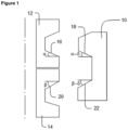
- FIG 1 shows schematically a jaw (10) connecting a connection element (12) and a wellhead (14).
- This jaw (10) comprises teeth (18) and (22) having angles different from the angles of the tooth (16) of the connection element (12) and different from the angle of the tooth (20) of the hub (14).
- the number of teeth of the jaw varies from one to four in each coupling region with the wellhead and the connection element, respectively, but is not limited to that number.
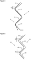
- Figure 2 shows an embodiment of the present invention
- this embodiment shows the relation between the angles of the teeth of the jaw (26) and the angles of the teeth of the connection element (24), and between the angles of the teeth of the jaw (26) and the angles of the teeth of the wellhead (28).
- the angles of the teeth of the connection element (24) and the teeth of the wellhead (28) are standardized by the manufacturers thereof, then, there is no variation of the teeth angles, as well as the distance among the teeth. Therefore, the present invention provides a configuration wherein the teeth of the jaw (26) have differentiated angles and differentiated spacings between them.
- the teeth (30) and (32) of the connection element (24) have the same angle ⁇
- the teeth (34) and (36) of the jaw (26) have differentiated angles
- the tooth (34) has an angle ⁇ - ⁇ 1
- the tooth (36) has an angle ⁇ - ⁇ 2, wherein ⁇ varies 0° ⁇ ⁇ ⁇ 1,75°.
- the wellhead (28) comprises teeth (38, 40, 42 and 44) with standardized angles ⁇ , in contrast, the teeth (46, 48, 50 and 52) of the jaw (26) have differentiated angulations ⁇ having a variation - ⁇ 1, - ⁇ 2, - ⁇ 3 and - ⁇ 4, respectively, with ⁇ varying 0° ⁇ ⁇ ⁇ 1,75°.
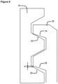
- Figure 3 shows the relation of the spaces between the teeth of the jaw (26) and the teeth of wellhead (28).
- the spacing d1 is the distance in the axial direction between the tooth (36) of the jaw (26) and the tooth (32) of the connection element (24) when the tooth (52) of the jaw (26) comes into contact with the tooth (44) of the wellhead (28), similarly, spacings (d2, d3 and d4) are the distances in the axial direction between the teeth of the jaw (26) and the teeth of the wellhead (28) when the tooth (52) of the jaw (26) comes into contact with the tooth (44) of the wellhead (28).
- the distance (d) between the teeth can vary from 0 ⁇ d ⁇ 1,50mm. The values used depend on the relative stiffness between the different components.
- the teeth of the jaw (26) are dimensioned to have differentiated angles and differentiated spacings first aiming at a non-uniform coupling.
- This concept relies on the fact that the tooth of the jaw (26) is in a pre-deforming position, such a way that, when the tooth of the jaw (26) undergoes a compression tension caused by the connector preload application process, the elastic deformation undergone by said tooth, evens out the tension distribution along the contact surface, making the operation more efficient.
- the number of teeth of the jaw (26) is defined according to the connector preload.
- the said jaw (26) preferably comprises from one to four teeth in the coupling region with the wellhead (28), and from one to two teeth in the coupling region with the connection element (24).
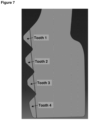
- Table 1 below shows the average tension and peak tension values of the connector for the teeth sections shown in Figure 7 according to the present invention, for the prior art connector (document US 7,614,453 ) and for a model having a jaw with equal spacing among teeth. Note that the average tension and peak tension values among the teeth of the present invention are smaller when compared with the results of document US 7,614,453 and the model having a jaw with equal spacing.
Description
- The present invention relates to a wellhead connector having a teeth configuration that allows a more uniform tension distribution between male and female.
- Such a configuration consists of a jaw profile comprising a differentiated spacing among teeth and differentiated teeth angles (between male and female). The present invention can be used on contact surfaces, through which the preload of connectors of any type, from terrestrial to subsea connectors, passes.
- Connectors are used to connect two types of equipment, usually cylindrical parts, and apply a certain preload therebetween. Therefore, connectors are commonly used in the oil and gas field, for example, by connecting the wellhead to the BOP.
- The connector is made up of multi-toothed jaws having a tooth profile that is used to apply a preload to the contact surface. Despite the male (connector jaw) and female (wellhead contact surface) have the same profile in order to be better engaged, the tension distribution, after material deformation, is not uniform. This fact is due to the stiffness difference of the components during the connector locking.
- Document
US 7,614,453 discloses a connector having jaws with non-uniform spacings between the connector teeth and also the wellhead surface. Such a configuration allows to distribute tension and contact forces more uniformly between the contact surfaces. - The present invention proposes a more efficient distribution configuration of tensions and contact forces between the teeth surfaces, making the locking mechanism more resistant to failure.
- The invention provides a system comprising a connection element, a wellhead and a connector according to
claim 1. - The connectors have the function to usually connect two cylindrical parts and apply a particular preload therebetween. For this purpose, each of the parts has a locking profile through which the load is transmitted to. These profiles always show angular locks, which influence the mechanical gain that is a characteristic of each type of connector. The parts that are connected can have profiles with a number of teeth ranging from one to four, but not limited to that number.
- The load transfer angles used in the art are the same between male and female. Equal angles generate a non-uniform tension distribution on the contact surfaces due to the non-uniform stiffness distribution to the components.
- The present invention discloses contact surfaces with differentiated angles and differentiated spacing which confer an extremely beneficial effect on the tension uniformity on the contact surfaces. The combination of angular differences and differentiated spacing of the teeth is an even more efficient solution.
- The proposed invention has the advantage of making the distribution of tensions on the contact surfaces more uniform, directly impacting on the sizing and optimization of the connector project.
- The connector according to the present invention comprises jaws with differentiated spacings and differentiated angles between the jaw and the contact surface in order to reach the intended goals:
- The present invention will be better understood from the accompanying illustrative drawings, which, in a schematic form and without limiting its scope, represent:
-
Figure 1 - Schematic concept of the present invention. -
Figure 2 - Schematic drawing of the jaw, wellhead and connection element teeth. -
Figure 3 - Schematic drawing of the contact of the jaw teeth with the wellhead teeth. -
Figure 4 - Spacing detailing between the jaw and wellhead teeth. -
Figure 5 - Spacing detailing between the jaw and wellhead teeth. -
Figure 6 - Spacing detailing between the jaw and connection element teeth. -
Figure 7 - Schematic drawing of the jaw teeth. - The present invention relates to a connector comprising a jaw (26) having a configuration to better distribute tensions on the contact surfaces of the teeth, i.e., it has contact surfaces with differentiated angles and differentiated spacings, conferring an extremely beneficial effect on the tension uniformity on the contact surfaces, solving the problem regarding the non-uniformity of the tension distribution on the teeth contact surfaces, and of the connectors in general, since the stiffness distribution of these teeth is also not uniform as well as the stiffness distribution in the wellhead is not uniform.
-
Figure 1 shows schematically a jaw (10) connecting a connection element (12) and a wellhead (14). This jaw (10) comprises teeth (18) and (22) having angles different from the angles of the tooth (16) of the connection element (12) and different from the angle of the tooth (20) of the hub (14). The number of teeth of the jaw varies from one to four in each coupling region with the wellhead and the connection element, respectively, but is not limited to that number. -
Figure 2 shows an embodiment of the present invention, this embodiment shows the relation between the angles of the teeth of the jaw (26) and the angles of the teeth of the connection element (24), and between the angles of the teeth of the jaw (26) and the angles of the teeth of the wellhead (28). Given the knowledge from the current art, the angles of the teeth of the connection element (24) and the teeth of the wellhead (28) are standardized by the manufacturers thereof, then, there is no variation of the teeth angles, as well as the distance among the teeth. Therefore, the present invention provides a configuration wherein the teeth of the jaw (26) have differentiated angles and differentiated spacings between them. As can be seen inFigure 2 , the teeth (30) and (32) of the connection element (24) have the same angle α, and the teeth (34) and (36) of the jaw (26) have differentiated angles, as can be seen inFigure 2 , the tooth (34) has an angle α-δ1 and the tooth (36) has an angle α-δ2, wherein δ varies 0° < δ ≤ 1,75°. - The wellhead (28) comprises teeth (38, 40, 42 and 44) with standardized angles β, in contrast, the teeth (46, 48, 50 and 52) of the jaw (26) have differentiated angulations β having a variation -γ1, -γ2, -γ3 and -γ4, respectively, with γ varying 0° < γ ≤ 1,75°.
-
Figure 3 shows the relation of the spaces between the teeth of the jaw (26) and the teeth of wellhead (28). An example of what occurs when a tooth of the jaw (26) comes into contact with the tooth of the wellhead (28), in this case, the tooth (52) comes into contact with the tooth (44) at the beginning of the connector preload application. At this time, the other teeth of the jaw (26) are not in contact with the wellhead (28) due to the difference of the angles and to the differentiated spacings abovementioned. Same situation occurs between the teeth of the jaw (26) and the connection element (24). - As can be seen in
Figures 4 to 6 , the spacing d1 is the distance in the axial direction between the tooth (36) of the jaw (26) and the tooth (32) of the connection element (24) when the tooth (52) of the jaw (26) comes into contact with the tooth (44) of the wellhead (28), similarly, spacings (d2, d3 and d4) are the distances in the axial direction between the teeth of the jaw (26) and the teeth of the wellhead (28) when the tooth (52) of the jaw (26) comes into contact with the tooth (44) of the wellhead (28). The distance (d) between the teeth can vary from 0 < d ≤ 1,50mm. The values used depend on the relative stiffness between the different components. - In order to even out the tension distribution along the contact surfaces, the teeth of the jaw (26) are dimensioned to have differentiated angles and differentiated spacings first aiming at a non-uniform coupling. This concept relies on the fact that the tooth of the jaw (26) is in a pre-deforming position, such a way that, when the tooth of the jaw (26) undergoes a compression tension caused by the connector preload application process, the elastic deformation undergone by said tooth, evens out the tension distribution along the contact surface, making the operation more efficient.
- The number of teeth of the jaw (26) is defined according to the connector preload. The said jaw (26) preferably comprises from one to four teeth in the coupling region with the wellhead (28), and from one to two teeth in the coupling region with the connection element (24).
- Table 1 below shows the average tension and peak tension values of the connector for the teeth sections shown in
Figure 7 according to the present invention, for the prior art connector (documentUS 7,614,453 ) and for a model having a jaw with equal spacing among teeth. Note that the average tension and peak tension values among the teeth of the present invention are smaller when compared with the results of documentUS 7,614,453 and the model having a jaw with equal spacing.Type of tension / Position Invention Prior art ( US 7,614,453 )Prior art (connector having equal spacing among teeth) Average Tension (MPa) - tooth 1433 447 751 Average Tension (MPa) - tooth 2311 381 606 Average Tension (MPa) - tooth 3240 193 159 Average Tension (MPa) - tooth 4172 200 14 Peak Tension (MPa) - tooth 1274 373 158 Peak Tension (MPa) - tooth 2344 514 306 Peak Tension (MPa) - tooth 3163 490 181 Peak Tension (MPa) - tooth 4160 451 9 - As the pressure exerted by the piston increase, the other teeth of the jaw (26) will come into contact with the teeth of the wellhead (28). Such a principle applies to the jaw (26) and the connection element (24).
Claims (8)
- System comprising a connection element (12, 24), a wellhead (14, 28) and a connector, the connector comprising a jaw (10, 26) having a plurality of teeth (18, 22, 34, 36, 46, 48, 50, 52) for connecting the connection element (12, 24) to the wellhead (14, 28),wherein the connection element (12, 24) comprises one tooth forming a first angle (α) or a plurality of teeth forming first equal angles, and the wellhead (14, 28) comprises one tooth forming a second angle (β) or a plurality of teeth forming second equal angles,wherein a face of each tooth (18, 22, 34, 36, 46, 48, 50, 52) of the jaw (10, 26) forms an angle (α-δ, β-δ) which is different from a corresponding angle (α, β) formed by a face of a tooth (16, 20, 30, 32, 38, 40, 42, 44) of the connection element (12, 24) or of the wellhead (14, 28), which faces said face of a tooth of the jaw (10, 26) in a position of connection of the connection element (12, 24) and the wellhead (14, 28); andthe teeth of the jaw (10, 26) are configured such that at least one spacing (d1-d4) is present in an axial direction defined by the system and between two opposite faces of a tooth of the jaw (10, 26) and a tooth of the connection element (12, 24) or of the wellhead (14, 28) when two other opposite faces of a tooth of the jaw (10, 26) and a tooth of the connection element (12, 24) or of the wellhead (14, 28) come into contact.
- System according to claim 1, characterized in that the jaw (10, 26) includes teeth with angles in relation to angles α of the teeth of the connection element (12, 24) and angles β of the teeth of the wellhead (14, 28), wherein:- two teeth (34,36) have angles α-δ1 and α-δ2, respectively; and- teeth (46, 48, 50, 52) have angles β having a variation -γ1, -γ2, -γ3 and -γ4, respectively.
- System according to claim 2, characterized in that the angles δ and γ are the same or different.
- System according to claim 2, characterized in that the angle δ is in the range of 0° < δ ≤ 1,75° and the angle γ is in the range of 0° < γ ≤ 1,75°.
- System according to claim 1, characterized in that spacings (d1) between teeth of the jaw (26) and teeth of the connection element (24) and spacings (d2-d4) between teeth of the jaw (26) and teeth of the wellhead (28) are in a range of 0 < d ≤ 1,5 mm.
- System according to claim 5, characterized in that the spacings (d1-d4) are the same or different.
- System according to claim 1, characterized in that the number of teeth of the jaw (26) is defined according to the connector preload.
- System according to claim 7, characterized in that said jaw (10, 26) has preferably from one to four teeth in the coupling region with the wellhead (14, 28), and from one to two teeth in the coupling region with the connection element (12, 24).
Applications Claiming Priority (2)
| Application Number | Priority Date | Filing Date | Title |
|---|---|---|---|
| BR102017025983-8A BR102017025983B1 (en) | 2017-12-01 | CONNECTOR | |
| PCT/BR2018/050414 WO2019104401A1 (en) | 2017-12-01 | 2018-11-12 | Connector |
Publications (3)
| Publication Number | Publication Date |
|---|---|
| EP3719250A1 EP3719250A1 (en) | 2020-10-07 |
| EP3719250A4 EP3719250A4 (en) | 2021-07-28 |
| EP3719250B1 true EP3719250B1 (en) | 2023-10-11 |
Family
ID=66663693
Family Applications (1)
| Application Number | Title | Priority Date | Filing Date |
|---|---|---|---|
| EP18883723.1A Active EP3719250B1 (en) | 2017-12-01 | 2018-11-12 | Connector |
Country Status (3)
| Country | Link |
|---|---|
| US (1) | US11492864B2 (en) |
| EP (1) | EP3719250B1 (en) |
| WO (1) | WO2019104401A1 (en) |
Families Citing this family (1)
| Publication number | Priority date | Publication date | Assignee | Title |
|---|---|---|---|---|
| BR112022008679A2 (en) * | 2019-11-06 | 2022-07-19 | Fmc Tech Inc | CLAMP TYPE WELL HEAD CONNECTOR SYSTEM |
Family Cites Families (8)
| Publication number | Priority date | Publication date | Assignee | Title |
|---|---|---|---|---|
| US4615544A (en) | 1982-02-16 | 1986-10-07 | Smith International, Inc. | Subsea wellhead system |
| FR2622247A1 (en) * | 1987-10-27 | 1989-04-28 | Vetco Gray Inc | DEVICE FOR ADJUSTING AND LOCKING THE VOLTAGE INSERTED INTO A CYLINDRICAL BODY. APPLICATION TO HEADS OF OIL WELLS |
| US4989479A (en) * | 1989-11-02 | 1991-02-05 | Cooper Industries, Inc. | Plier jaws |
| GB0222321D0 (en) * | 2002-09-25 | 2002-10-30 | Weatherford Lamb | Expandable connection |
| US7380607B2 (en) * | 2004-06-15 | 2008-06-03 | Vetco Gray Inc. | Casing hanger with integral load ring |
| FR2880097B1 (en) * | 2004-12-23 | 2007-03-30 | Philippe Nobileau | SEALED PIPE CONNECTOR |
| US7614453B2 (en) * | 2006-06-01 | 2009-11-10 | Cameron International Corporation | Stress distributing wellhead connector |
| US10527207B2 (en) * | 2016-12-09 | 2020-01-07 | Dril-Quip, Inc. | High capacity universal connector |
-
2018
- 2018-11-12 EP EP18883723.1A patent/EP3719250B1/en active Active
- 2018-11-12 WO PCT/BR2018/050414 patent/WO2019104401A1/en unknown
- 2018-11-12 US US16/768,835 patent/US11492864B2/en active Active
Also Published As
| Publication number | Publication date |
|---|---|
| BR102017025983A2 (en) | 2019-06-25 |
| WO2019104401A1 (en) | 2019-06-06 |
| EP3719250A4 (en) | 2021-07-28 |
| US11492864B2 (en) | 2022-11-08 |
| US20210164311A1 (en) | 2021-06-03 |
| EP3719250A1 (en) | 2020-10-07 |
Similar Documents
| Publication | Publication Date | Title |
|---|---|---|
| US7927135B1 (en) | Coaxial connector with a coupling body with grip fingers engaging a wedge of a stabilizing body | |
| US20140327238A1 (en) | Coupling Having Arcuate Stiffness Ribs | |
| EP3719250B1 (en) | Connector | |
| US10184597B2 (en) | Stress reducing thread form | |
| EP1761751A1 (en) | Pressure sensor | |
| US20200232743A1 (en) | Multiple Flange Crush Washer | |
| EP2283203B1 (en) | Pipe connection | |
| US11767906B2 (en) | Transmission and method for producing a transmission having a housing | |
| MX2019015289A (en) | Rolling block restraint connector. | |
| JP6137080B2 (en) | Slab forging method | |
| KR101537381B1 (en) | Bending press apparatus for spring back reduction | |
| US20170122470A1 (en) | Joint restraint devices and methods of using same | |
| CN109440033B (en) | Process method for eliminating residual stress of arc-shaped forge piece | |
| WO2020154704A3 (en) | Common contact surfaces for use in the manufacture, packaging, delivery, and assessment of biopharmaceutical products | |
| US20210131458A1 (en) | Packing nut locking apparatus and methods | |
| KR20130084984A (en) | Chain, and method for manufacturing a chain | |
| EP2937612B1 (en) | Threaded joint for pipe | |
| DE102017217364B4 (en) | Electrolysis cell with preload coupling, method for mounting the preload coupling and use of the preload coupling | |
| MX2022008550A (en) | Inkjet method for producing a spectacle lens. | |
| EP3098496A1 (en) | Threaded joint for pipe | |
| DE102008048972A1 (en) | Beam pipe arrangement with a connecting device | |
| CN216666159U (en) | Self-adaptive fastening structure | |
| US11248689B2 (en) | Actuator with a spindle drive and rear-axle steering system | |
| CN209959727U (en) | Locking and anti-loosening device and locking system of aircraft engine rotor | |
| JP4823208B2 (en) | Manufacturing method of roller chain link plate |
Legal Events
| Date | Code | Title | Description |
|---|---|---|---|
| STAA | Information on the status of an ep patent application or granted ep patent |
Free format text: STATUS: THE INTERNATIONAL PUBLICATION HAS BEEN MADE |
|
| PUAI | Public reference made under article 153(3) epc to a published international application that has entered the european phase |
Free format text: ORIGINAL CODE: 0009012 |
|
| STAA | Information on the status of an ep patent application or granted ep patent |
Free format text: STATUS: REQUEST FOR EXAMINATION WAS MADE |
|
| 17P | Request for examination filed |
Effective date: 20200529 |
|
| AK | Designated contracting states |
Kind code of ref document: A1 Designated state(s): AL AT BE BG CH CY CZ DE DK EE ES FI FR GB GR HR HU IE IS IT LI LT LU LV MC MK MT NL NO PL PT RO RS SE SI SK SM TR |
|
| AX | Request for extension of the european patent |
Extension state: BA ME |
|
| DAV | Request for validation of the european patent (deleted) | ||
| DAX | Request for extension of the european patent (deleted) | ||
| A4 | Supplementary search report drawn up and despatched |
Effective date: 20210628 |
|
| RIC1 | Information provided on ipc code assigned before grant |
Ipc: E21B 33/038 20060101AFI20210622BHEP |
|
| STAA | Information on the status of an ep patent application or granted ep patent |
Free format text: STATUS: EXAMINATION IS IN PROGRESS |
|
| 17Q | First examination report despatched |
Effective date: 20220708 |
|
| GRAP | Despatch of communication of intention to grant a patent |
Free format text: ORIGINAL CODE: EPIDOSNIGR1 |
|
| STAA | Information on the status of an ep patent application or granted ep patent |
Free format text: STATUS: GRANT OF PATENT IS INTENDED |
|
| RIC1 | Information provided on ipc code assigned before grant |
Ipc: F16L 37/08 20060101ALI20230426BHEP Ipc: E21B 33/038 20060101AFI20230426BHEP |
|
| INTG | Intention to grant announced |
Effective date: 20230517 |
|
| GRAS | Grant fee paid |
Free format text: ORIGINAL CODE: EPIDOSNIGR3 |
|
| GRAA | (expected) grant |
Free format text: ORIGINAL CODE: 0009210 |
|
| STAA | Information on the status of an ep patent application or granted ep patent |
Free format text: STATUS: THE PATENT HAS BEEN GRANTED |
|
| AK | Designated contracting states |
Kind code of ref document: B1 Designated state(s): AL AT BE BG CH CY CZ DE DK EE ES FI FR GB GR HR HU IE IS IT LI LT LU LV MC MK MT NL NO PL PT RO RS SE SI SK SM TR |
|
| REG | Reference to a national code |
Ref country code: GB Ref legal event code: FG4D |
|
| REG | Reference to a national code |
Ref country code: CH Ref legal event code: EP |
|
| REG | Reference to a national code |
Ref country code: DE Ref legal event code: R096 Ref document number: 602018059370 Country of ref document: DE |
|
| REG | Reference to a national code |
Ref country code: IE Ref legal event code: FG4D |
|
| PGFP | Annual fee paid to national office [announced via postgrant information from national office to epo] |
Ref country code: GB Payment date: 20231214 Year of fee payment: 6 |
|
| PGFP | Annual fee paid to national office [announced via postgrant information from national office to epo] |
Ref country code: FR Payment date: 20231228 Year of fee payment: 6 |
|
| REG | Reference to a national code |
Ref country code: LT Ref legal event code: MG9D |
|
| REG | Reference to a national code |
Ref country code: NL Ref legal event code: MP Effective date: 20231011 |
|
| REG | Reference to a national code |
Ref country code: NO Ref legal event code: T2 Effective date: 20231011 |
|
| REG | Reference to a national code |
Ref country code: AT Ref legal event code: MK05 Ref document number: 1620397 Country of ref document: AT Kind code of ref document: T Effective date: 20231011 |
|
| PG25 | Lapsed in a contracting state [announced via postgrant information from national office to epo] |
Ref country code: NL Free format text: LAPSE BECAUSE OF FAILURE TO SUBMIT A TRANSLATION OF THE DESCRIPTION OR TO PAY THE FEE WITHIN THE PRESCRIBED TIME-LIMIT Effective date: 20231011 |
|
| PG25 | Lapsed in a contracting state [announced via postgrant information from national office to epo] |
Ref country code: GR Free format text: LAPSE BECAUSE OF FAILURE TO SUBMIT A TRANSLATION OF THE DESCRIPTION OR TO PAY THE FEE WITHIN THE PRESCRIBED TIME-LIMIT Effective date: 20240112 |
|
| PG25 | Lapsed in a contracting state [announced via postgrant information from national office to epo] |
Ref country code: IS Free format text: LAPSE BECAUSE OF FAILURE TO SUBMIT A TRANSLATION OF THE DESCRIPTION OR TO PAY THE FEE WITHIN THE PRESCRIBED TIME-LIMIT Effective date: 20240211 |
|
| PG25 | Lapsed in a contracting state [announced via postgrant information from national office to epo] |
Ref country code: LT Free format text: LAPSE BECAUSE OF FAILURE TO SUBMIT A TRANSLATION OF THE DESCRIPTION OR TO PAY THE FEE WITHIN THE PRESCRIBED TIME-LIMIT Effective date: 20231011 |