EP3719215A1 - Work machine cab and work machine - Google Patents
Work machine cab and work machine Download PDFInfo
- Publication number
- EP3719215A1 EP3719215A1 EP19812429.9A EP19812429A EP3719215A1 EP 3719215 A1 EP3719215 A1 EP 3719215A1 EP 19812429 A EP19812429 A EP 19812429A EP 3719215 A1 EP3719215 A1 EP 3719215A1
- Authority
- EP
- European Patent Office
- Prior art keywords
- door
- cab
- actuator
- work machine
- angle range
- Prior art date
- Legal status (The legal status is an assumption and is not a legal conclusion. Google has not performed a legal analysis and makes no representation as to the accuracy of the status listed.)
- Granted
Links
Images



Classifications
-
- E—FIXED CONSTRUCTIONS
- E02—HYDRAULIC ENGINEERING; FOUNDATIONS; SOIL SHIFTING
- E02F—DREDGING; SOIL-SHIFTING
- E02F9/00—Component parts of dredgers or soil-shifting machines, not restricted to one of the kinds covered by groups E02F3/00 - E02F7/00
- E02F9/16—Cabins, platforms, or the like, for drivers
-
- E—FIXED CONSTRUCTIONS
- E02—HYDRAULIC ENGINEERING; FOUNDATIONS; SOIL SHIFTING
- E02F—DREDGING; SOIL-SHIFTING
- E02F9/00—Component parts of dredgers or soil-shifting machines, not restricted to one of the kinds covered by groups E02F3/00 - E02F7/00
- E02F9/16—Cabins, platforms, or the like, for drivers
- E02F9/163—Structures to protect drivers, e.g. cabins, doors for cabins; Falling object protection structure [FOPS]; Roll over protection structure [ROPS]
-
- B—PERFORMING OPERATIONS; TRANSPORTING
- B62—LAND VEHICLES FOR TRAVELLING OTHERWISE THAN ON RAILS
- B62D—MOTOR VEHICLES; TRAILERS
- B62D33/00—Superstructures for load-carrying vehicles
- B62D33/06—Drivers' cabs
- B62D33/0617—Drivers' cabs for tractors or off-the-road vehicles
-
- E—FIXED CONSTRUCTIONS
- E05—LOCKS; KEYS; WINDOW OR DOOR FITTINGS; SAFES
- E05F—DEVICES FOR MOVING WINGS INTO OPEN OR CLOSED POSITION; CHECKS FOR WINGS; WING FITTINGS NOT OTHERWISE PROVIDED FOR, CONCERNED WITH THE FUNCTIONING OF THE WING
- E05F15/00—Power-operated mechanisms for wings
-
- E—FIXED CONSTRUCTIONS
- E02—HYDRAULIC ENGINEERING; FOUNDATIONS; SOIL SHIFTING
- E02F—DREDGING; SOIL-SHIFTING
- E02F3/00—Dredgers; Soil-shifting machines
- E02F3/04—Dredgers; Soil-shifting machines mechanically-driven
- E02F3/28—Dredgers; Soil-shifting machines mechanically-driven with digging tools mounted on a dipper- or bucket-arm, i.e. there is either one arm or a pair of arms, e.g. dippers, buckets
- E02F3/283—Dredgers; Soil-shifting machines mechanically-driven with digging tools mounted on a dipper- or bucket-arm, i.e. there is either one arm or a pair of arms, e.g. dippers, buckets with a single arm pivoted directly on the chassis
-
- E—FIXED CONSTRUCTIONS
- E05—LOCKS; KEYS; WINDOW OR DOOR FITTINGS; SAFES
- E05F—DEVICES FOR MOVING WINGS INTO OPEN OR CLOSED POSITION; CHECKS FOR WINGS; WING FITTINGS NOT OTHERWISE PROVIDED FOR, CONCERNED WITH THE FUNCTIONING OF THE WING
- E05F1/00—Closers or openers for wings, not otherwise provided for in this subclass
- E05F1/08—Closers or openers for wings, not otherwise provided for in this subclass spring-actuated, e.g. for horizontally sliding wings
- E05F1/10—Closers or openers for wings, not otherwise provided for in this subclass spring-actuated, e.g. for horizontally sliding wings for swinging wings, e.g. counterbalance
- E05F1/1091—Closers or openers for wings, not otherwise provided for in this subclass spring-actuated, e.g. for horizontally sliding wings for swinging wings, e.g. counterbalance with a gas spring
-
- E—FIXED CONSTRUCTIONS
- E05—LOCKS; KEYS; WINDOW OR DOOR FITTINGS; SAFES
- E05Y—INDEXING SCHEME ASSOCIATED WITH SUBCLASSES E05D AND E05F, RELATING TO CONSTRUCTION ELEMENTS, ELECTRIC CONTROL, POWER SUPPLY, POWER SIGNAL OR TRANSMISSION, USER INTERFACES, MOUNTING OR COUPLING, DETAILS, ACCESSORIES, AUXILIARY OPERATIONS NOT OTHERWISE PROVIDED FOR, APPLICATION THEREOF
- E05Y2201/00—Constructional elements; Accessories therefor
- E05Y2201/40—Motors; Magnets; Springs; Weights; Accessories therefor
- E05Y2201/404—Function thereof
- E05Y2201/41—Function thereof for closing
-
- E—FIXED CONSTRUCTIONS
- E05—LOCKS; KEYS; WINDOW OR DOOR FITTINGS; SAFES
- E05Y—INDEXING SCHEME ASSOCIATED WITH SUBCLASSES E05D AND E05F, RELATING TO CONSTRUCTION ELEMENTS, ELECTRIC CONTROL, POWER SUPPLY, POWER SIGNAL OR TRANSMISSION, USER INTERFACES, MOUNTING OR COUPLING, DETAILS, ACCESSORIES, AUXILIARY OPERATIONS NOT OTHERWISE PROVIDED FOR, APPLICATION THEREOF
- E05Y2201/00—Constructional elements; Accessories therefor
- E05Y2201/40—Motors; Magnets; Springs; Weights; Accessories therefor
- E05Y2201/404—Function thereof
- E05Y2201/422—Function thereof for opening
-
- E—FIXED CONSTRUCTIONS
- E05—LOCKS; KEYS; WINDOW OR DOOR FITTINGS; SAFES
- E05Y—INDEXING SCHEME ASSOCIATED WITH SUBCLASSES E05D AND E05F, RELATING TO CONSTRUCTION ELEMENTS, ELECTRIC CONTROL, POWER SUPPLY, POWER SIGNAL OR TRANSMISSION, USER INTERFACES, MOUNTING OR COUPLING, DETAILS, ACCESSORIES, AUXILIARY OPERATIONS NOT OTHERWISE PROVIDED FOR, APPLICATION THEREOF
- E05Y2201/00—Constructional elements; Accessories therefor
- E05Y2201/40—Motors; Magnets; Springs; Weights; Accessories therefor
- E05Y2201/47—Springs
- E05Y2201/478—Gas springs
-
- E—FIXED CONSTRUCTIONS
- E05—LOCKS; KEYS; WINDOW OR DOOR FITTINGS; SAFES
- E05Y—INDEXING SCHEME ASSOCIATED WITH SUBCLASSES E05D AND E05F, RELATING TO CONSTRUCTION ELEMENTS, ELECTRIC CONTROL, POWER SUPPLY, POWER SIGNAL OR TRANSMISSION, USER INTERFACES, MOUNTING OR COUPLING, DETAILS, ACCESSORIES, AUXILIARY OPERATIONS NOT OTHERWISE PROVIDED FOR, APPLICATION THEREOF
- E05Y2900/00—Application of doors, windows, wings or fittings thereof
- E05Y2900/50—Application of doors, windows, wings or fittings thereof for vehicles
- E05Y2900/518—Application of doors, windows, wings or fittings thereof for vehicles for working vehicles
-
- E—FIXED CONSTRUCTIONS
- E05—LOCKS; KEYS; WINDOW OR DOOR FITTINGS; SAFES
- E05Y—INDEXING SCHEME ASSOCIATED WITH SUBCLASSES E05D AND E05F, RELATING TO CONSTRUCTION ELEMENTS, ELECTRIC CONTROL, POWER SUPPLY, POWER SIGNAL OR TRANSMISSION, USER INTERFACES, MOUNTING OR COUPLING, DETAILS, ACCESSORIES, AUXILIARY OPERATIONS NOT OTHERWISE PROVIDED FOR, APPLICATION THEREOF
- E05Y2900/00—Application of doors, windows, wings or fittings thereof
- E05Y2900/50—Application of doors, windows, wings or fittings thereof for vehicles
- E05Y2900/53—Type of wing
- E05Y2900/531—Doors
Definitions
- the present disclosure relates to a cab for a work machine and a work machine including the cab.
- U.S. Patent Application Publication No. 2017/0362869 discloses that an access door of an operator cab is biased in a direction away from the cab body by the force of gravity.
- the door disclosed in the above-mentioned document is subjected to a force that comes from the weight of the door in a direction from the closed position to the open position. After the closed door is unlocked, the door starts moving in the opening direction.
- the door of the prior art moves unintentionally, it may be a problem when a window of the door is under cleaning or the like.
- the present disclosure provides a cab for a work machine and a work machine capable of preventing the door from opening against an operator's intention.
- a cab for a work machine includes a cab body, a door, and a biasing member.
- the cab body is formed with a doorway.
- the door is rotatably supported on the cab body.
- the door opens and closes the doorway.
- the biasing member biases the door in the closing direction.
- Fig. 1 is a side view illustrating a wheel loader 10 according to an embodiment of the present disclosure.
- the wheel loader 10 includes a front frame 12, a rear frame 14, front wheels 26, rear wheels 27, a work implement 16, a cab (an operator's compartment) 30, and a rear structure 18.
- the direction in which the wheel loader 10 travels straight is defined as a front-rear direction of the wheel loader 10.
- the side on which the work implement 16 is disposed relative to the front frame 12 and the rear frame 14 is defined as a front side
- the side opposite to the front side is defined as a rear side.
- the left-right direction of the wheel loader 10 is defined as a direction orthogonal to the front-rear direction in planar view.
- the right side and the left side in the left-right direction when viewed from the front direction correspond to the right direction and the left direction, respectively.
- the vertical direction of the wheel loader 10 is defined as a direction orthogonal to a plane defined by the front-rear direction and the left-right direction.
- the side downward the ground is defined as a lower side
- the side upward the sky is defined as an upper side.
- the front-rear direction corresponds to the front-rear direction of the operator sitting on a driver's seat in the cab 30.
- the left-right direction corresponds to the left-right direction of the operator sitting on the driver's seat.
- the left-right direction corresponds to the width direction of the wheel loader 10.
- the vertical direction corresponds to the vertical direction of the operator sitting on the driver's seat.
- the direction facing the operator sitting on the driver's seat corresponds to the front direction, and the direction behind the operator sitting on the driver's seat corresponds to the rear direction.
- the right side and the left side when the operator is sitting on the driver's seat and facing toward the front correspond to the right direction and the left direction, respectively.
- the side down to the feet of the operator sitting on the driver's seat corresponds to the lower side
- the side upper to the head corresponds to the upper side.
- the front frame 12 and the rear frame 14 constitute an articulate body frame.
- the front frame 12 is provided in front of the rear frame 14.
- the front frame 12 is rotatably coupled to the rear frame 14 by a center pin (not shown).
- the center of rotation of the front frame 12 relative to the rear frame 14 corresponds to an axis extending in the vertical direction.
- the front frame 12 is coupled to the rear frame 14 via steering cylinders (not shown).
- the steering cylinders are provided in pairs on the left side and the right side, respectively.
- the front frame 12 rotates to the left side or to the right side about the center pin as one steering cylinder extends and the other steering cylinder contracts or vice versa.
- the front wheels 26 and the rear wheels 27 are travelling wheels of the wheel loader 10.
- the front wheels 26 are provided on the front frame 12.
- the front wheels 26 are provided in pairs on the left side and the right side, respectively.
- the rear wheels 27 are provided on the rear frame 14.
- the rear wheels 27 are provided in pairs on the left side and the right side, respectively.
- the work implement 16 is provided on the front frame 12.
- the work implement 16 includes a boom 21, a bucket 24, a boom cylinder 21A, a bell crank 22, a bucket cylinder 24A, and a link 23.
- the cab 30 and the rear structure 18 are provided on the rear frame 14.
- the cab 30 is provided behind the work implement 16.
- the operator enters the room of the cab 30 and operates the wheel loader 10.
- the operator gets into the cab 30 so as to drive the wheel loader 10 and operate the work implement 16.
- the rear structure 18 is provided behind the cab 30.
- the rear structure 18 includes a hydraulic oil tank, an engine, a hydraulic pump, and the like.
- the front frame 12, the rear frame 14 and the rear structure 18 constitute the body of the wheel loader 10.
- the cab 30 includes a cab body 31.
- the cab body 31 defines an interior space of the cab 30.
- the cab body 31 is formed by assembling steel plates and transparent windows in combination.
- the cab body 31 has a hexagonal shape in top view.
- the cab body 31 includes a front surface 32, a rear surface 33, a left surface 34, a right surface, a diagonally left front surface 36, and a diagonally right front surface.
- the front surface 32 is provided facing forward.
- the rear surface 33 is provided facing rearward.
- the length of the front surface 32 in the left-right direction is shorter than the length of the rear surface 33 in the left-right direction.
- the right surface is provided facing rightward.
- the right surface is disposed between the front surface 32 and the rear surface 33.
- the right surface is continuous with the right end of the rear surface 33.
- the left surface 34 is provided facing leftward.
- the left surface 34 is disposed between the front surface 32 and the rear surface 33.
- the left surface 34 is continuous with the left end of the rear surface 33.
- the diagonally left front surface 36 is provided facing diagonally left forward.
- the diagonally left front surface 36 is disposed between the front surface 32 and the left surface 34.
- the diagonally left front surface 36 is continuous with the left end of the front surface 32 and the front end of the left surface 34.
- the diagonally right front surface is provided facing diagonally right forward.
- the diagonally right front surface is disposed between the front surface 32 and the right surface.
- the diagonally right front surface is continuous with the right end of the front surface 32 and the front end of the right surface. The distance between the diagonally left front surface 36 and the diagonally right front surface in the left-right direction decreases from the rear side toward the front side.
- the cab body 31 of the cab 30 is not limited to the hexagonal shape in top view as described above, and it may have, for example, a rectangular shape in top view.
- the cab 30 includes a left door 61 and a right door. Both the left door 61 and the right door are provided on the cab body 31 so that they may be opened or closed as necessary.
- the left door 61 is provided on the left side of the cab body 31.
- the door 61 is provided on the left surface 34.
- the door 61 is an automatic door that may be opened and closed automatically.
- the right door is provided on the right side of the cab body 31.
- the right door is provided on the right surface.
- the right door is a manual door that may be opened and closed manually.
- the cab body 31 is formed with a doorway.
- the doorway is an entrance provided in the cab body 31 for the operator to get in and out of the cab 30.
- the doorway has a rectangular shape as a whole in which the vertical direction corresponds to the longitudinal direction.
- the doorway is provided on the left surface 34 and the right surface, respectively.
- the door 61 is provided for the doorway which is provided on the left surface 34.
- the door 61 may be rotated between a closed position (a position illustrated in Fig. 1 and Figs. 2 and 3 to be described later) in which the doorway is closed and an open position (a position illustrated in Fig. 4 to be described later) in which the doorway is opened.
- the door 61 is configured to open and close the doorway.
- the door 61 includes a hinge 62.
- the door 61 is rotatably supported on the cab body 31 via the hinge 62.
- the door 61 is configured to be rotatable around the hinge 62 between the closed position and the open position.
- the door 61 is configured to open outward from the cab 30.
- the door 61 is a rear hinge door in which the hinge 62 is arranged at the rear side of the doorway.
- the rotation angle of the door 61 from the closed position to the open position is greater than 90°.
- the rotation angle of the door 61 from the closed position to the open position is 120° or more.
- the door 61 When the door 61 is at the closed position, the door 61 is parallel to the left surface 34. When the door 61 is at the open position, the door 61 extends diagonally left rearward from the rear end of the opening formed by the doorway. The door 61 at the open position is located rearward than the doorway.
- the wheel loader 10 further includes a ladder 41.
- the cab 30 is arranged above the ladder 41.
- the ladder 41 is used by the operator to move up and down between the ground and the cab 30.
- the ladder 41 is attached to the rear frame 14.
- the ladder 41 includes a plurality of steps 42.
- Each step 42 serves as a foothold on which the operator steps.
- the plurality of steps 42 are arranged at an interval in the vertical direction.
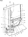
- Fig. 2 is a perspective view illustrating the door 61 at the closed position when viewed from the inside of the cab 30.
- the wheel loader 10 further includes a handrail 64, a handrail 65, and a handrail 66.
- the handrail 64, the handrail 65 and the handrail 66 are used by the operator as handrails to move up and down between the ground and the cab 30 or get in and out of the cab 30.
- the handrail 64, the handrail 65 and the handrail 66 each is in the form of a bar that may be gripped by the operator.
- the handrail 64, the handrail 65 and the handrail 66 are attached to the door 61.
- the handrail 64, the handrail 65 and the handrail 66 are provided on an indoor surface of the door 61 that is located inside the cab 30 when the door 61 is at the closed position.
- the handrail 64 and the handrail 66 are adjacent to the rear end of the doorway in the front-rear direction.
- the handrail 64 and the handrail 66 extend in the vertical direction.
- the handrail 65 extends in the horizontal direction. When the door 61 is at the open position, the handrail 64, the handrail 65 and the handrail 66 are located outside the cab 30.
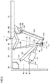
- FIG. 3 is a planar view schematically illustrating the configuration of an opening and closing device for the door 61.
- the wheel loader 10 further includes an actuator 91.
- the actuator 91 generates a driving force to move the closed door 61 in the opening direction.
- the actuator 91 performs an opening operation on the door 61.
- the opening operation refers to such an operation that the door 61 is moved from the closed position to the open position.
- the actuator 91 further generates a driving force to move the opened door 61 in the closing direction.
- the actuator 91 performs a closing operation on the door 61.
- the closing operation refers to such an operation that the door 61 is moved from the open position to the closed position.
- the actuator 91 includes a rod 94 and a support 96.
- the rod 94 can do reciprocating motion, and the length of the rod 94 protruding from the actuator 91 is extendable.
- the actuator 91 is supported on the cab body 31 via the support 96.
- a bracket 40 is fixed on a floor 37 of the cab body 31.
- a coupling pin 97 is inserted through a through hole formed in the bracket 40 to fix the support 96.
- the support 96 (the actuator 91) is fixed to the cab body 31 in such a manner that it is rotatable about the coupling pin 97.
- the wheel loader 10 further includes an operation unit 70.
- the operation unit 70 is operated by the operator when the operator opens or closes the door 61.
- the operation unit 70 includes, for example, a push button to be pressed by the operator.
- the operation unit 70 may include an open button for opening the door 61 and a close button for closing the door 61.
- the operation unit 70 includes a first operation unit (not shown) provided inside the cab 30 and a second operation unit 76 provided outside the cab 30.
- the first operation unit is used by the operator to open or close the door 61 from the inside of the cab 30.
- the first operation unit is attached to, for example, a right front pillar of the cab 30.
- the second operation unit 76 is used by the operator to open or close the door 61 from the outside of the cab 30.
- the second operation unit 76 is attached to the ladder 41.
- the wheel loader 10 further includes an open position locking unit 111 and a closed position locking unit 121.
- the closed position locking unit 121 is configured to lock the door 61 at the closed position.
- the open position locking unit 111 is configured to lock the door 61 at the open position.
- the closed position locking unit 121 is provided inside the cab 30.
- the closed position locking unit 121 includes a movable catcher 122 and a striker 123 that may be engaged with the catcher 122.
- the catcher 122 is provided on the indoor surface of the door 61.
- the striker 123 is attached to the left front pillar of the cab 30. When the catcher 122 is engaged with the striker 123, the door 61 is locked at the closed position (locking operation). When the catcher 122 is disengaged from the striker 123, the door 61 is released from the closed position (unlocking operation).
- the open position locking unit 111 is provided on the indoor surface of the door 61. Similar to the closed position locking unit 121, the open position locking unit 111 includes a movable latch and a striker that may be engaged with the latch.
- the wheel loader 10 further includes a power transmission device that transmits a driving force generated by the actuator 91 to the door 61.
- the power transmission device includes a first link 130, a second link 140, and a third link 150.
- the first link 130 and the second link 140 each is in the form of a rod. Similar to the support 96 of the actuator 91, the base end of the first link 130 is rotatably attached to the bracket 40 by a coupling pin 131. The distal end of the first link 130 is coupled to the base end of the second link 140 by a coupling pin 132 in such a manner that they are rotatable relative to each other.
- the rod 94 of the actuator 91 is coupled to a position between the base end and the distal end of the first link 130 by a coupling pin 95 in such a manner that they are rotatable relative to each other.
- the third link 150 is in the form of a plate.
- the third link 150 is rotatable relative to the cab body 31 and rotatable relative to the door 61 about a rotation shaft 151.
- the distal end of the second link 140 is coupled to the third link 150 by a coupling pin 142 in such a manner that they are rotatable relative to each other.
- the peripheral edge of the third link 150 may come into contact with a contact member 158 formed integrally with the door 61.
- the contact member 158 is included in the power transmission device that transmits a driving force generated by the actuator 91 to the door 61.
- the driving force for opening the door 61 is transmitted to the door 61.
- the driving force for closing the door 61 is transmitted to the door 61.
- the third link 150 is coupled to a locking link 160 in the form of a cable and a locking link 162 in the form of a cable.
- the locking link 160 and the locking link 162 are not drawn for simplicity of illustration.
- the locking link 160 is coupled to the catcher 122 of the closed position locking unit 121.
- the driving force of the actuator 91 is transmitted to the catcher 122 via the locking link 160, the catcher 122 is disengaged from the striker 123, and thereby, the door 61 that is locked by the closed position locking unit 121 is released.
- the driving force to unlock the door 61 that is locked by the closed position locking unit 121 is generated by the actuator 91.
- the locking link 162 is coupled to the latch of the open position locking unit 111.
- the driving force of the actuator 91 is transmitted to the latch via the locking link 162
- the latch is disengaged from the striker, and thereby, the door 61 that is locked by the open position locking unit 111 is released.
- the driving force to unlock the door 61 that is locked by the open position locking unit 111 is generated by the actuator 91.
- the wheel loader 10 further includes a gas spring 170.
- the gas spring 170 includes a cylinder 177, a rod 175, and a mount 171.
- the cylinder 177 is sealed with compressed gas.
- the rod 175 can reciprocate relative to the cylinder 177.
- the rod 175 is biased by the pressure of the compressed gas in a direction of extending from the cylinder 177. Therefore, the gas spring 170 is biased to increase its length.
- the cab body 31 includes a bracket 174.
- the bracket 174 is fixed on the floor 37 of the cab body 31 via a fixing seat 173.
- the mount 171 of the gas spring 170 is coupled to the bracket 174 by a coupling pin 172 in such a manner that they are rotatable relative to each other.
- the rod 175 is coupled to a gas spring fixing bracket 63 by a coupling pin 176 in such a manner that they are rotatable relative to each other.
- the gas spring fixing bracket 63 is attached to the indoor surface of the door 61, and is formed integrally with the door 61.
- the straight line L indicated by a two-dot chain line in Fig. 3 is such a straight line that passes through the center of the hinge 62 (a hinge center 62C illustrated in Fig. 2 ) and the center of the coupling pin 172 of the gas spring 170.
- the coupling pin 176 that couples the gas spring 170 and the door 61 (the gas spring fixing bracket 63) is located in the rear of the straight line L.
- the door 61 illustrated in Fig. 3 is subjected to a force in the clockwise direction around the hinge 62 from the gas spring 170.
- the door 61 at the closed position is biased by the gas spring 170 in the closing direction.
- Fig. 4 is a planar view schematically illustrating the configuration of the opening/closing device when the door is at the open position. As illustrated in Fig. 4 , when the rod 94 of the actuator 91 extends, the first link 130 is forced to rotate counterclockwise about the coupling pin 131, whereby the second link 140 and the third link 150 are moved toward the outside of the cab 30.
- the driving force of the actuator 91 is applied to the door 61 via the first link 130, the second link 140, and the third link 150.
- the door 61 Upon receiving the driving force, the door 61 is forced to rotate counterclockwise around the hinge 62, and is moved to the open position.
- Fig. 4 illustrates that the doorway 39 is open.
- the actuator 91 is completely located inside the cab body 31 without being located outside the cab 30.
- the coupling pin 176 that couples the gas spring 170 and the door 61 (the gas spring fixing bracket 63) is located in front of the straight line L.
- the door 61 illustrated in Fig. 4 is subjected to a force in the counterclockwise direction around the hinge 62 from the gas spring 170.
- the door 61 at the open position is biased by the gas spring 170 in the opening direction.
- the gas spring 170 constitutes the biasing member of the present embodiment that biases the door 61 in both the closing direction and the opening direction.
- the gas spring 170 biases the door 61 in the closing direction.
- the gas spring 170 biases the door 61 in the opening direction.
- the coupling pin 176 is located on the straight line L.
- Fig. 5 is a schematic planar view illustrating a position of the door 61 where the coupling pin 176 is located on the straight line L.
- Fig. 6 is a schematic planar view illustrating a first angle range.
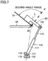
- Fig. 7 is a schematic planar view illustrating a second angle range.
- the door 61 illustrated in Fig. 6 is at the closed position.
- the door 61 illustrated in Fig. 7 is at the open position.
- the broken line illustrates the position of the door 61 when the coupling pin 176 is located on the straight line L as illustrated in Fig. 5 .
- the range between the closed position and the position of the door 61 where the coupling pin 176 is located on the straight line L is referred to as a first angle range.
- the range between the open position and the position of the door 61 where the coupling pin 176 is located on the straight line L is referred to as a second angle range.
- the first angle range and the second angle range each represents a partial range of the rotation angle of the door 61 relative to the cab body 31.
- the first angle range includes a state when the door 61 is fully closed.
- the second angle range includes a state when the door 61 is fully open.
- the biasing force that biases the rod 175 of the gas spring 170 to extend generates a clockwise moment around the hinge 62 in Fig. 6 .
- this moment acts on the door 61 via the coupling pin 176 and the gas spring fixing bracket 63, the door 61 is biased in the clockwise direction around the hinge 62.
- the gas spring 170 biases the door 61 in the closing direction when the door 61 is positioned in the first angle range.
- the biasing force that biases the rod 175 of the gas spring 170 to extend generates a counterclockwise moment around the hinge 62 in Fig. 7 .
- this moment acts on the door 61 via the coupling pin 176 and the gas spring fixing bracket 63, the door 61 is biased in the counterclockwise direction around the hinge 62.
- the gas spring 170 biases the door 61 in the opening direction when the door 61 is positioned in the second angle range.
- the length of the rod 94 of the actuator 91 is decreased, and a driving force to move the door 61 in the closing direction is transmitted from the actuator 91 to the door 61.
- the gas spring 170 biases the door 61 in the opening direction.
- the door 61 is forced to move in the closing direction by the driving force of the actuator 91 against the biasing force of the gas spring 170.
- the door 61 When the door 61 is positioned in the first angle range, the door 61 is forced to move in the closing direction by the biasing force of the gas spring 170. At this time, no driving force is applied by the actuator 91 to move the door 61 in the closing direction. While the door 61 is being moved in the closing direction, when the position of the door 61 is changed from the second angle range to the first angle range, the driving force generated by the actuator 91 cannot be transmitted to the door 61. The switching of the power transmission is performed by the rotation of the third link 150 around the rotation shaft 151.
- the third link 150 is configured to rotate relative to the cab body 31 and rotate relative to the door 61. Due to the rotation of the third link 150, the driving force generated by the actuator 91 is not transmitted to the door 61.
- the third link 150 functions as a play member in the present embodiment which provides a play in a path for transmitting the driving force generated by the actuator 91 to the door 61.
- the door 61 is supported by the third link 150 with a play relative to the cab body 31.
- the cab 30 includes a gas spring 170 which biases the door 61 in the closing direction. Since the gas spring 170 biases the door 61 in the closing direction after the door 61 locked by the closed position locking unit 121 is released, the door 61 is prevented from being opened unintentionally. Even though the door 61 is slightly opened, it will be automatically closed by the biasing force of the gas spring 170. Therefore, according to the cab 30 of the present embodiment, it is possible to prevent the door 61 at the closed position from being opened against the operator's intention.
- the cab 30 includes an actuator 91.
- the actuator 91 generates a driving force to move the closed door 61 in the opening direction.
- the door 61 can be moved from the closed position to the open position by the driving force generated by the actuator 91.
- the gas spring 170 biases the door 61 in the opening direction. Since the gas spring 170 biases the door 61 in the opening direction after the door 61 locked by the open position locking unit 111 is released, the door 61 is prevented from being closed unintentionally. Therefore, it is possible to prevent the door 61 at the open position from being closed against the operator's intention.
- the actuator 91 further generates a driving force to move the opened door 61 in the closing direction. Since a single actuator 91 may be used to generate a driving force to move the door 61 in the opening direction and a driving force to move the door 61 in the closing direction, it is possible to simplify the configuration and reduce the cost.
- the cab 30 includes a third link 150 in a power transmission device that transmits the driving force generated by the actuator 91 to the door 61.
- the third link 150 provides a play that prevents the driving force generated by the actuator 91 from being transmitted to the door 61.
- the play between the cab body 31 and the door 61 may be realized by, for example, forming a slot in the third link 150 and engaging the second link 140 in the slot of the third link 150.
- the play is provided by the relative rotation of the plate-shaped third link 150 of the present embodiment, which makes it possible to improve the durability of the play member which provides the play.
- the power transmission device including the third link 150 as a play member between the actuator 91 and the door 61 has been described.
- the arrangement of the play member in the power transmission device is not limited to that in the example of the present embodiment.
- the play member for providing a play may be arranged between the actuator 91 and the cab body 31.
- the gas spring 170 has been described as an example of the biasing member that biases the door 61 in the closing direction and the opening direction.
- the biasing member is not limited to the gas spring 170, it may be any biasing member such as a coil spring or the like.
- the present disclosure is applicable to various work machines including a cab.
- the work machine described in the present disclosure is not limited to a wheel loader, it may be a bulldozer, a hydraulic excavator, a motor grader, a crane or a forestry machine.
Landscapes
- Engineering & Computer Science (AREA)
- Mining & Mineral Resources (AREA)
- Civil Engineering (AREA)
- General Engineering & Computer Science (AREA)
- Structural Engineering (AREA)
- Chemical & Material Sciences (AREA)
- Combustion & Propulsion (AREA)
- Transportation (AREA)
- Mechanical Engineering (AREA)
- Component Parts Of Construction Machinery (AREA)
Abstract
Description
- The present disclosure relates to a cab for a work machine and a work machine including the cab.
- Conventionally,
U.S. Patent Application Publication No. 2017/0362869 (PTL 1) discloses that an access door of an operator cab is biased in a direction away from the cab body by the force of gravity. -
- The door disclosed in the above-mentioned document is subjected to a force that comes from the weight of the door in a direction from the closed position to the open position. After the closed door is unlocked, the door starts moving in the opening direction. However, if the door of the prior art moves unintentionally, it may be a problem when a window of the door is under cleaning or the like.
- The present disclosure provides a cab for a work machine and a work machine capable of preventing the door from opening against an operator's intention.
- According to the present disclosure, a cab for a work machine is provided. The cab includes a cab body, a door, and a biasing member. The cab body is formed with a doorway. The door is rotatably supported on the cab body. The door opens and closes the doorway. The biasing member biases the door in the closing direction.
- According to the present disclosure, it is possible to prevent the door from being opened against the operator's intention.
-
-
Fig. 1 is a side view illustrating a wheel loader according to an embodiment of the present disclosure; -
Fig. 2 is a perspective view illustrating a door at a closed position when viewed from the inside of a cab; -
Fig. 3 is a planar view schematically illustrating the configuration of an opening/closing device for the door; -
Fig. 4 is a planar view schematically illustrating the configuration of the opening/closing device when the door is at the open position; -
Fig. 5 is a schematic planar view illustrating a position of the door where a coupling pin is located on a straight line L; -
Fig. 6 is a schematic planar view illustrating a first angle range; and -
Fig. 7 is a schematic planar view illustrating a second angle range. - Hereinafter, embodiments will be described with reference to the drawings. In the following description, the same components will be denoted by the same reference numerals, and may have the same names and the same functions, and thereby, the detailed description thereof will not be repeated.
- In the present embodiment, the configuration of a wheel loader which serves as an example of a work machine to which the idea of the present disclosure may be applied will be described firstly.
Fig. 1 is a side view illustrating awheel loader 10 according to an embodiment of the present disclosure. - As illustrated in
Fig. 1 , thewheel loader 10 includes afront frame 12, arear frame 14,front wheels 26,rear wheels 27, a work implement 16, a cab (an operator's compartment) 30, and arear structure 18. - In the following description, the direction in which the
wheel loader 10 travels straight is defined as a front-rear direction of thewheel loader 10. In the front-rear direction of thewheel loader 10, the side on which thework implement 16 is disposed relative to thefront frame 12 and therear frame 14 is defined as a front side, and the side opposite to the front side is defined as a rear side. The left-right direction of thewheel loader 10 is defined as a direction orthogonal to the front-rear direction in planar view. The right side and the left side in the left-right direction when viewed from the front direction correspond to the right direction and the left direction, respectively. The vertical direction of thewheel loader 10 is defined as a direction orthogonal to a plane defined by the front-rear direction and the left-right direction. In the vertical direction, the side downward the ground is defined as a lower side, and the side upward the sky is defined as an upper side. - The front-rear direction corresponds to the front-rear direction of the operator sitting on a driver's seat in the
cab 30. The left-right direction corresponds to the left-right direction of the operator sitting on the driver's seat. The left-right direction corresponds to the width direction of thewheel loader 10. The vertical direction corresponds to the vertical direction of the operator sitting on the driver's seat. The direction facing the operator sitting on the driver's seat corresponds to the front direction, and the direction behind the operator sitting on the driver's seat corresponds to the rear direction. The right side and the left side when the operator is sitting on the driver's seat and facing toward the front correspond to the right direction and the left direction, respectively. The side down to the feet of the operator sitting on the driver's seat corresponds to the lower side, and the side upper to the head corresponds to the upper side. - The
front frame 12 and therear frame 14 constitute an articulate body frame. Thefront frame 12 is provided in front of therear frame 14. Thefront frame 12 is rotatably coupled to therear frame 14 by a center pin (not shown). The center of rotation of thefront frame 12 relative to therear frame 14 corresponds to an axis extending in the vertical direction. - The
front frame 12 is coupled to therear frame 14 via steering cylinders (not shown). The steering cylinders are provided in pairs on the left side and the right side, respectively. Thefront frame 12 rotates to the left side or to the right side about the center pin as one steering cylinder extends and the other steering cylinder contracts or vice versa. - The
front wheels 26 and therear wheels 27 are travelling wheels of thewheel loader 10. Thefront wheels 26 are provided on thefront frame 12. Thefront wheels 26 are provided in pairs on the left side and the right side, respectively. Therear wheels 27 are provided on therear frame 14. Therear wheels 27 are provided in pairs on the left side and the right side, respectively. - The
work implement 16 is provided on thefront frame 12. Thework implement 16 includes aboom 21, abucket 24, aboom cylinder 21A, abell crank 22, abucket cylinder 24A, and alink 23. - The
cab 30 and therear structure 18 are provided on therear frame 14. Thecab 30 is provided behind the work implement 16. The operator enters the room of thecab 30 and operates thewheel loader 10. The operator gets into thecab 30 so as to drive thewheel loader 10 and operate the work implement 16. - The
rear structure 18 is provided behind thecab 30. Therear structure 18 includes a hydraulic oil tank, an engine, a hydraulic pump, and the like. Thefront frame 12, therear frame 14 and therear structure 18 constitute the body of thewheel loader 10. - Next, the configuration of the
cab 30 will be described. Thecab 30 includes acab body 31. Thecab body 31 defines an interior space of thecab 30. Thecab body 31 is formed by assembling steel plates and transparent windows in combination. - The
cab body 31 has a hexagonal shape in top view. Thecab body 31 includes afront surface 32, arear surface 33, aleft surface 34, a right surface, a diagonally leftfront surface 36, and a diagonally right front surface. - The
front surface 32 is provided facing forward. Therear surface 33 is provided facing rearward. The length of thefront surface 32 in the left-right direction is shorter than the length of therear surface 33 in the left-right direction. The right surface is provided facing rightward. The right surface is disposed between thefront surface 32 and therear surface 33. The right surface is continuous with the right end of therear surface 33. Theleft surface 34 is provided facing leftward. Theleft surface 34 is disposed between thefront surface 32 and therear surface 33. Theleft surface 34 is continuous with the left end of therear surface 33. - The diagonally left
front surface 36 is provided facing diagonally left forward. The diagonally leftfront surface 36 is disposed between thefront surface 32 and theleft surface 34. The diagonally leftfront surface 36 is continuous with the left end of thefront surface 32 and the front end of theleft surface 34. The diagonally right front surface is provided facing diagonally right forward. The diagonally right front surface is disposed between thefront surface 32 and the right surface. The diagonally right front surface is continuous with the right end of thefront surface 32 and the front end of the right surface. The distance between the diagonally leftfront surface 36 and the diagonally right front surface in the left-right direction decreases from the rear side toward the front side. - The
cab body 31 of thecab 30 is not limited to the hexagonal shape in top view as described above, and it may have, for example, a rectangular shape in top view. - The
cab 30 includes aleft door 61 and a right door. Both theleft door 61 and the right door are provided on thecab body 31 so that they may be opened or closed as necessary. Theleft door 61 is provided on the left side of thecab body 31. Thedoor 61 is provided on theleft surface 34. Thedoor 61 is an automatic door that may be opened and closed automatically. The right door is provided on the right side of thecab body 31. The right door is provided on the right surface. The right door is a manual door that may be opened and closed manually. - Next, the configuration of the
door 61 and the configuration around thedoor 61 will be described. - The
cab body 31 is formed with a doorway. The doorway is an entrance provided in thecab body 31 for the operator to get in and out of thecab 30. The doorway has a rectangular shape as a whole in which the vertical direction corresponds to the longitudinal direction. The doorway is provided on theleft surface 34 and the right surface, respectively. - The
door 61 is provided for the doorway which is provided on theleft surface 34. Thedoor 61 may be rotated between a closed position (a position illustrated inFig. 1 andFigs. 2 and3 to be described later) in which the doorway is closed and an open position (a position illustrated inFig. 4 to be described later) in which the doorway is opened. Thedoor 61 is configured to open and close the doorway. - The
door 61 includes ahinge 62. Thedoor 61 is rotatably supported on thecab body 31 via thehinge 62. Thedoor 61 is configured to be rotatable around thehinge 62 between the closed position and the open position. Thedoor 61 is configured to open outward from thecab 30. Thedoor 61 is a rear hinge door in which thehinge 62 is arranged at the rear side of the doorway. - The rotation angle of the
door 61 from the closed position to the open position is greater than 90°. Preferably, the rotation angle of thedoor 61 from the closed position to the open position is 120° or more. - When the
door 61 is at the closed position, thedoor 61 is parallel to theleft surface 34. When thedoor 61 is at the open position, thedoor 61 extends diagonally left rearward from the rear end of the opening formed by the doorway. Thedoor 61 at the open position is located rearward than the doorway. - The
wheel loader 10 further includes aladder 41. Thecab 30 is arranged above theladder 41. Theladder 41 is used by the operator to move up and down between the ground and thecab 30. - The
ladder 41 is attached to therear frame 14. Theladder 41 includes a plurality ofsteps 42. Eachstep 42 serves as a foothold on which the operator steps. The plurality ofsteps 42 are arranged at an interval in the vertical direction. -
Fig. 2 is a perspective view illustrating thedoor 61 at the closed position when viewed from the inside of thecab 30. As illustrated inFigs. 1 and2 , thewheel loader 10 further includes ahandrail 64, ahandrail 65, and ahandrail 66. - The
handrail 64, thehandrail 65 and thehandrail 66 are used by the operator as handrails to move up and down between the ground and thecab 30 or get in and out of thecab 30. Thehandrail 64, thehandrail 65 and thehandrail 66 each is in the form of a bar that may be gripped by the operator. - The
handrail 64, thehandrail 65 and thehandrail 66 are attached to thedoor 61. Thehandrail 64, thehandrail 65 and thehandrail 66 are provided on an indoor surface of thedoor 61 that is located inside thecab 30 when thedoor 61 is at the closed position. Thehandrail 64 and thehandrail 66 are adjacent to the rear end of the doorway in the front-rear direction. Thehandrail 64 and thehandrail 66 extend in the vertical direction. Thehandrail 65 extends in the horizontal direction. When thedoor 61 is at the open position, thehandrail 64, thehandrail 65 and thehandrail 66 are located outside thecab 30. - Next, the configuration of a device automatically opening and closing the
door 61 will be described.Fig. 3 is a planar view schematically illustrating the configuration of an opening and closing device for thedoor 61. - As illustrated in
Figs. 2 and3 , thewheel loader 10 further includes anactuator 91. Theactuator 91 generates a driving force to move theclosed door 61 in the opening direction. Theactuator 91 performs an opening operation on thedoor 61. The opening operation refers to such an operation that thedoor 61 is moved from the closed position to the open position. Theactuator 91 further generates a driving force to move the openeddoor 61 in the closing direction. Theactuator 91 performs a closing operation on thedoor 61. The closing operation refers to such an operation that thedoor 61 is moved from the open position to the closed position. - The
actuator 91 includes arod 94 and asupport 96. Therod 94 can do reciprocating motion, and the length of therod 94 protruding from theactuator 91 is extendable. Theactuator 91 is supported on thecab body 31 via thesupport 96. As illustrated inFig. 3 , abracket 40 is fixed on afloor 37 of thecab body 31. Acoupling pin 97 is inserted through a through hole formed in thebracket 40 to fix thesupport 96. Thus, the support 96 (the actuator 91) is fixed to thecab body 31 in such a manner that it is rotatable about thecoupling pin 97. - As illustrated in
Fig. 1 , thewheel loader 10 further includes anoperation unit 70. Theoperation unit 70 is operated by the operator when the operator opens or closes thedoor 61. Theoperation unit 70 includes, for example, a push button to be pressed by the operator. Theoperation unit 70 may include an open button for opening thedoor 61 and a close button for closing thedoor 61. - The
operation unit 70 includes a first operation unit (not shown) provided inside thecab 30 and asecond operation unit 76 provided outside thecab 30. The first operation unit is used by the operator to open or close thedoor 61 from the inside of thecab 30. The first operation unit is attached to, for example, a right front pillar of thecab 30. Thesecond operation unit 76 is used by the operator to open or close thedoor 61 from the outside of thecab 30. Thesecond operation unit 76 is attached to theladder 41. - As illustrated in
Fig. 2 , thewheel loader 10 further includes an openposition locking unit 111 and a closedposition locking unit 121. The closedposition locking unit 121 is configured to lock thedoor 61 at the closed position. The openposition locking unit 111 is configured to lock thedoor 61 at the open position. - The closed
position locking unit 121 is provided inside thecab 30. The closedposition locking unit 121 includes amovable catcher 122 and astriker 123 that may be engaged with thecatcher 122. Thecatcher 122 is provided on the indoor surface of thedoor 61. Thestriker 123 is attached to the left front pillar of thecab 30. When thecatcher 122 is engaged with thestriker 123, thedoor 61 is locked at the closed position (locking operation). When thecatcher 122 is disengaged from thestriker 123, thedoor 61 is released from the closed position (unlocking operation). - The open
position locking unit 111 is provided on the indoor surface of thedoor 61. Similar to the closedposition locking unit 121, the openposition locking unit 111 includes a movable latch and a striker that may be engaged with the latch. - The
wheel loader 10 further includes a power transmission device that transmits a driving force generated by theactuator 91 to thedoor 61. The power transmission device includes afirst link 130, asecond link 140, and athird link 150. - The
first link 130 and thesecond link 140 each is in the form of a rod. Similar to thesupport 96 of theactuator 91, the base end of thefirst link 130 is rotatably attached to thebracket 40 by acoupling pin 131. The distal end of thefirst link 130 is coupled to the base end of thesecond link 140 by acoupling pin 132 in such a manner that they are rotatable relative to each other. Therod 94 of theactuator 91 is coupled to a position between the base end and the distal end of thefirst link 130 by acoupling pin 95 in such a manner that they are rotatable relative to each other. - The
third link 150 is in the form of a plate. Thethird link 150 is rotatable relative to thecab body 31 and rotatable relative to thedoor 61 about arotation shaft 151. The distal end of thesecond link 140 is coupled to thethird link 150 by acoupling pin 142 in such a manner that they are rotatable relative to each other. - The peripheral edge of the
third link 150 may come into contact with acontact member 158 formed integrally with thedoor 61. Thecontact member 158 is included in the power transmission device that transmits a driving force generated by theactuator 91 to thedoor 61. When a part of the peripheral edge of thethird link 150 comes into contact with a part of thecontact member 158, the driving force for opening thedoor 61 is transmitted to thedoor 61. When the other part of the periphery edge of thethird link 150 comes into contact with the other part of thecontact member 158, the driving force for closing thedoor 61 is transmitted to thedoor 61. - As illustrated in
Fig. 2 , thethird link 150 is coupled to alocking link 160 in the form of a cable and alocking link 162 in the form of a cable. InFig. 3 andFig. 4 to be described later, thelocking link 160 and thelocking link 162 are not drawn for simplicity of illustration. - The
locking link 160 is coupled to thecatcher 122 of the closedposition locking unit 121. When the driving force of theactuator 91 is transmitted to thecatcher 122 via thelocking link 160, thecatcher 122 is disengaged from thestriker 123, and thereby, thedoor 61 that is locked by the closedposition locking unit 121 is released. The driving force to unlock thedoor 61 that is locked by the closedposition locking unit 121 is generated by theactuator 91. - The
locking link 162 is coupled to the latch of the openposition locking unit 111. When the driving force of theactuator 91 is transmitted to the latch via thelocking link 162, the latch is disengaged from the striker, and thereby, thedoor 61 that is locked by the openposition locking unit 111 is released. The driving force to unlock thedoor 61 that is locked by the openposition locking unit 111 is generated by theactuator 91. - As illustrated in
Figs. 2 and3 , thewheel loader 10 further includes agas spring 170. Thegas spring 170 includes acylinder 177, arod 175, and amount 171. Thecylinder 177 is sealed with compressed gas. Therod 175 can reciprocate relative to thecylinder 177. Therod 175 is biased by the pressure of the compressed gas in a direction of extending from thecylinder 177. Therefore, thegas spring 170 is biased to increase its length. - The
cab body 31 includes abracket 174. Thebracket 174 is fixed on thefloor 37 of thecab body 31 via a fixingseat 173. Themount 171 of thegas spring 170 is coupled to thebracket 174 by acoupling pin 172 in such a manner that they are rotatable relative to each other. Therod 175 is coupled to a gasspring fixing bracket 63 by acoupling pin 176 in such a manner that they are rotatable relative to each other. The gasspring fixing bracket 63 is attached to the indoor surface of thedoor 61, and is formed integrally with thedoor 61. - The straight line L indicated by a two-dot chain line in
Fig. 3 is such a straight line that passes through the center of the hinge 62 (ahinge center 62C illustrated inFig. 2 ) and the center of thecoupling pin 172 of thegas spring 170. When thedoor 61 illustrated inFig. 3 is at the closed position, thecoupling pin 176 that couples thegas spring 170 and the door 61 (the gas spring fixing bracket 63) is located in the rear of the straight line L. Thedoor 61 illustrated inFig. 3 is subjected to a force in the clockwise direction around thehinge 62 from thegas spring 170. Thedoor 61 at the closed position is biased by thegas spring 170 in the closing direction. -
Fig. 4 is a planar view schematically illustrating the configuration of the opening/closing device when the door is at the open position. As illustrated inFig. 4 , when therod 94 of theactuator 91 extends, thefirst link 130 is forced to rotate counterclockwise about thecoupling pin 131, whereby thesecond link 140 and thethird link 150 are moved toward the outside of thecab 30. - The driving force of the
actuator 91 is applied to thedoor 61 via thefirst link 130, thesecond link 140, and thethird link 150. Upon receiving the driving force, thedoor 61 is forced to rotate counterclockwise around thehinge 62, and is moved to the open position.Fig. 4 illustrates that thedoorway 39 is open. When thedoor 61 is at the open position, theactuator 91 is completely located inside thecab body 31 without being located outside thecab 30. - When the
door 61 illustrated inFig. 4 is at the open position, thecoupling pin 176 that couples thegas spring 170 and the door 61 (the gas spring fixing bracket 63) is located in front of the straight line L. Thedoor 61 illustrated inFig. 4 is subjected to a force in the counterclockwise direction around thehinge 62 from thegas spring 170. Thedoor 61 at the open position is biased by thegas spring 170 in the opening direction. Thegas spring 170 constitutes the biasing member of the present embodiment that biases thedoor 61 in both the closing direction and the opening direction. - As described above, when the
coupling pin 176 is located in the rear of the straight line L, thegas spring 170 biases thedoor 61 in the closing direction. When thecoupling pin 176 is located in front of the straight line L, thegas spring 170 biases thedoor 61 in the opening direction. When thedoor 61 is at a specific position between a fully closed state and a fully open state, thecoupling pin 176 is located on the straight line L. -
Fig. 5 is a schematic planar view illustrating a position of thedoor 61 where thecoupling pin 176 is located on the straight line L.Fig. 6 is a schematic planar view illustrating a first angle range.Fig. 7 is a schematic planar view illustrating a second angle range. Thedoor 61 illustrated inFig. 6 is at the closed position. Thedoor 61 illustrated inFig. 7 is at the open position. InFigs. 6 and7 , the broken line illustrates the position of thedoor 61 when thecoupling pin 176 is located on the straight line L as illustrated inFig. 5 . - As illustrated in
Fig. 6 , the range between the closed position and the position of thedoor 61 where thecoupling pin 176 is located on the straight line L is referred to as a first angle range. As illustrated inFig. 7 , the range between the open position and the position of thedoor 61 where thecoupling pin 176 is located on the straight line L is referred to as a second angle range. The first angle range and the second angle range each represents a partial range of the rotation angle of thedoor 61 relative to thecab body 31. The first angle range includes a state when thedoor 61 is fully closed. The second angle range includes a state when thedoor 61 is fully open. When thedoor 61 is positioned in the first angle range, thecoupling pin 176 is located in the rear of the straight line L. When thedoor 61 is positioned in the second angle range, thecoupling pin 176 is located in front of the straight line L. - When the
door 61 is positioned in the first angle range, the biasing force that biases therod 175 of thegas spring 170 to extend generates a clockwise moment around thehinge 62 inFig. 6 . When this moment acts on thedoor 61 via thecoupling pin 176 and the gasspring fixing bracket 63, thedoor 61 is biased in the clockwise direction around thehinge 62. Thegas spring 170 biases thedoor 61 in the closing direction when thedoor 61 is positioned in the first angle range. - When the
door 61 is in the second angle range, the biasing force that biases therod 175 of thegas spring 170 to extend generates a counterclockwise moment around thehinge 62 inFig. 7 . When this moment acts on thedoor 61 via thecoupling pin 176 and the gasspring fixing bracket 63, thedoor 61 is biased in the counterclockwise direction around thehinge 62. Thegas spring 170 biases thedoor 61 in the opening direction when thedoor 61 is positioned in the second angle range. - When the
door 61 is moved from the open position to the closed position, the length of therod 94 of theactuator 91 is decreased, and a driving force to move thedoor 61 in the closing direction is transmitted from theactuator 91 to thedoor 61. When thedoor 61 is positioned in the second angle range, thegas spring 170 biases thedoor 61 in the opening direction. However, thedoor 61 is forced to move in the closing direction by the driving force of theactuator 91 against the biasing force of thegas spring 170. - When the
door 61 is positioned in the first angle range, thedoor 61 is forced to move in the closing direction by the biasing force of thegas spring 170. At this time, no driving force is applied by theactuator 91 to move thedoor 61 in the closing direction. While thedoor 61 is being moved in the closing direction, when the position of thedoor 61 is changed from the second angle range to the first angle range, the driving force generated by theactuator 91 cannot be transmitted to thedoor 61. The switching of the power transmission is performed by the rotation of thethird link 150 around therotation shaft 151. - More specifically, as illustrated in
Figs. 3 and4 , thethird link 150 is configured to rotate relative to thecab body 31 and rotate relative to thedoor 61. Due to the rotation of thethird link 150, the driving force generated by theactuator 91 is not transmitted to thedoor 61. Thethird link 150 functions as a play member in the present embodiment which provides a play in a path for transmitting the driving force generated by theactuator 91 to thedoor 61. Thedoor 61 is supported by thethird link 150 with a play relative to thecab body 31. - Next, the function and effects of the present embodiment will be described.
- In the present embodiment, as illustrated in
Fig. 3 , thecab 30 includes agas spring 170 which biases thedoor 61 in the closing direction. Since thegas spring 170 biases thedoor 61 in the closing direction after thedoor 61 locked by the closedposition locking unit 121 is released, thedoor 61 is prevented from being opened unintentionally. Even though thedoor 61 is slightly opened, it will be automatically closed by the biasing force of thegas spring 170. Therefore, according to thecab 30 of the present embodiment, it is possible to prevent thedoor 61 at the closed position from being opened against the operator's intention. - As illustrated in
Fig. 3 , thecab 30 includes anactuator 91. Theactuator 91 generates a driving force to move theclosed door 61 in the opening direction. Thus, thedoor 61 can be moved from the closed position to the open position by the driving force generated by theactuator 91. - As illustrated in
Figs. 4 and7 , when thedoor 61 is positioned in the second angle range in which thedoor 61 is fully opened or almost fully opened, thegas spring 170 biases thedoor 61 in the opening direction. Since thegas spring 170 biases thedoor 61 in the opening direction after thedoor 61 locked by the openposition locking unit 111 is released, thedoor 61 is prevented from being closed unintentionally. Therefore, it is possible to prevent thedoor 61 at the open position from being closed against the operator's intention. - The
actuator 91 further generates a driving force to move the openeddoor 61 in the closing direction. Since asingle actuator 91 may be used to generate a driving force to move thedoor 61 in the opening direction and a driving force to move thedoor 61 in the closing direction, it is possible to simplify the configuration and reduce the cost. - As illustrated in
Figs. 2 to 4 , thecab 30 includes athird link 150 in a power transmission device that transmits the driving force generated by theactuator 91 to thedoor 61. Thethird link 150 provides a play that prevents the driving force generated by the actuator 91 from being transmitted to thedoor 61. When thedoor 61 is moved in the closing direction to the first angle range (Fig. 6 ) in which thedoor 61 is fully closed or almost fully closed, the driving force generated by theactuator 91 is not transmitted to thedoor 61. - As mentioned above, while the
door 61 is being moved in the closing direction, no driving force is applied from theactuator 91, thedoor 61 is closed only by the biasing force of thegas spring 170, and thus, thedoor 61 biased in the closing direction by thegas spring 170 is supported by theactuator 91. Thereby, even if the operator's finger or arm is caught between thedoor 61 that is being closed and thecab body 31, the operator may quickly pull out his/her arm before an excessively great force is applied to the operator's finger or arm. - The play between the
cab body 31 and thedoor 61 may be realized by, for example, forming a slot in thethird link 150 and engaging thesecond link 140 in the slot of thethird link 150. Thus, the play is provided by the relative rotation of the plate-shapedthird link 150 of the present embodiment, which makes it possible to improve the durability of the play member which provides the play. - As illustrated in
Figs. 3 and4 , the power transmission device including thethird link 150 as a play member between the actuator 91 and thedoor 61 has been described. The arrangement of the play member in the power transmission device is not limited to that in the example of the present embodiment. For example, the play member for providing a play may be arranged between the actuator 91 and thecab body 31. - The
gas spring 170 has been described as an example of the biasing member that biases thedoor 61 in the closing direction and the opening direction. However, the biasing member is not limited to thegas spring 170, it may be any biasing member such as a coil spring or the like. However, it is advantageous to use thegas spring 170 since it may reduce the biasing member in size or it is easier to control the opening and closing movement of thedoor 61. - The present disclosure is applicable to various work machines including a cab. The work machine described in the present disclosure is not limited to a wheel loader, it may be a bulldozer, a hydraulic excavator, a motor grader, a crane or a forestry machine.
- It should be understood that the embodiments disclosed herein have been presented for the purpose of illustration and description but not limited in all aspects. It is intended that the scope of the present invention is not limited to the description above but defined by the scope of the claims and encompasses all modifications equivalent in meaning and scope to the claims.
- 10: wheel loader; 16: work implement; 30: cab; 31: cab body; 34: left surface; 38: left rear pillar; 39: doorway; 40: bracket; 61: door; 62: hinge; 62c: hinge center; 63: gas spring fixing bracket; 70: operation unit; 76: second operation unit; 91: actuator; 94, 175: rod; 95, 97, 131, 132, 142, 172, 176: coupling pin; 96: support; 111: open position locking unit; 121: closed position locking unit; 122: catcher; 123: striker; 130: first link; 140: second link; 150: third link; 151: rotation shaft; 160: locking link; 162: locking link; 170: gas spring; 171: mount; 173: fixing seat; 174: bracket; 177: cylinder; L: straight line
Claims (8)
- A cab for a work machine, the cab comprising:a cab body which is formed with a doorway;a door which is rotatably supported on the cab body so as to open and close the doorway; anda biasing member which biases the door in a closing direction.
- The cab for a work machine according to claim 1, further comprising an actuator that generates a driving force to move the closed door in an opening direction.
- The cab for a work machine according to claim 2, wherein
the biasing member biases the door in the closing direction when a rotation angle of the door relative to the cab body is in a first angle range which includes a fully closed state, and biases the door in the opening direction when the rotation angle is in a second angle range which includes a fully open state and is larger than the first angle range. - The work machine cab according to claim 3, wherein
the actuator further generates a driving force to move the opened door in the closing direction. - The cab for a work machine according to claim 4, further comprising a power transmission device that transmits the driving force generated by the actuator to the door,
the power transmission device includes a play member, and
the play member provides a play that prevents the driving force generated by the actuator from being transmitted to the door. - The cab for a work machine according to claim 5, wherein
while the door is being moved in the closing direction, the play member transmits the driving force generated by the actuator to the door if the rotation angle is in the second angle range, and prevents the drive force generated by the actuator from being transmitted to the door if the rotation angle is changed from the second angle range to the first angle range. - The cab for a work machine according to claim 1, wherein
the biasing member biases the door in the closing direction when a rotation angle of the door relative to the cab body is in a first angle range which includes a fully closed state, and biases the door in the opening direction when the rotation angle is in a second angle range which includes a fully open state and is larger than the first angle range. - A work machine comprising:a work implement; anda cab according to any one of claims 1 to 7, in which an operator who operates the work implement is seated.
Applications Claiming Priority (2)
| Application Number | Priority Date | Filing Date | Title |
|---|---|---|---|
| JP2018102490A JP7049921B2 (en) | 2018-05-29 | 2018-05-29 | Work machine cab, and work machine |
| PCT/JP2019/009884 WO2019230114A1 (en) | 2018-05-29 | 2019-03-12 | Work machine cab and work machine |
Publications (3)
| Publication Number | Publication Date |
|---|---|
| EP3719215A1 true EP3719215A1 (en) | 2020-10-07 |
| EP3719215A4 EP3719215A4 (en) | 2021-08-18 |
| EP3719215B1 EP3719215B1 (en) | 2024-04-24 |
Family
ID=68697262
Family Applications (1)
| Application Number | Title | Priority Date | Filing Date |
|---|---|---|---|
| EP19812429.9A Active EP3719215B1 (en) | 2018-05-29 | 2019-03-12 | Work machine cab and work machine |
Country Status (5)
| Country | Link |
|---|---|
| US (1) | US11773566B2 (en) |
| EP (1) | EP3719215B1 (en) |
| JP (1) | JP7049921B2 (en) |
| CN (1) | CN111601931B (en) |
| WO (1) | WO2019230114A1 (en) |
Families Citing this family (6)
| Publication number | Priority date | Publication date | Assignee | Title |
|---|---|---|---|---|
| US11203893B2 (en) * | 2017-04-24 | 2021-12-21 | Assa Abloy Entrance Systems Ab | Swing door operator |
| IT202100008540A1 (en) * | 2021-04-06 | 2022-10-06 | Manitou Italia Srl | TELEHANDLER WITH EASY GETTING UP AND DOWN. |
| JP7717002B2 (en) * | 2022-02-04 | 2025-08-01 | 日立建機株式会社 | Work machinery |
| DE102023131660A1 (en) * | 2023-11-14 | 2025-05-15 | Manitowoc Crane Group France Sas | Crane cabin door system |
| US12497811B2 (en) | 2023-12-01 | 2025-12-16 | Caterpillar Inc. | Door hinge cushioning arrangement |
| JP2025115605A (en) * | 2024-01-26 | 2025-08-07 | 株式会社小松製作所 | Work machine and work machine control method |
Family Cites Families (15)
| Publication number | Priority date | Publication date | Assignee | Title |
|---|---|---|---|---|
| JPS55119875A (en) | 1979-03-06 | 1980-09-13 | Nippon Air Brake Co | Device for automatically opening*closing vehicle door |
| JP3767485B2 (en) | 2002-01-28 | 2006-04-19 | コベルコ建機株式会社 | Opening and closing mechanism of link type door of cabin of construction machine |
| JP2004143687A (en) | 2002-10-22 | 2004-05-20 | Shin Caterpillar Mitsubishi Ltd | Door opening/closing structure of working machine |
| CN101368463A (en) * | 2004-07-14 | 2009-02-18 | 尤利乌斯·布卢姆有限公司 | Actuating mechanism for a pivotably mounted actuating arm |
| US7347488B2 (en) | 2005-08-31 | 2008-03-25 | Caterpillar Inc. | Vehicle cab including centrally-located “A post” |
| JP4875875B2 (en) * | 2005-09-22 | 2012-02-15 | 昭和スプリング株式会社 | Door closing device |
| US7703835B2 (en) * | 2006-08-11 | 2010-04-27 | Weeda Dewey J | Secondary door and temperature control system and method |
| US7770959B2 (en) * | 2006-10-30 | 2010-08-10 | Gm Global Technology Operations, Inc. | Door actuation systems using active materials |
| JP2008196262A (en) | 2007-02-15 | 2008-08-28 | Hitachi Constr Mach Co Ltd | Auxiliary door handle device |
| JP4953914B2 (en) | 2007-05-18 | 2012-06-13 | 株式会社小松製作所 | Cab door |
| KR101556413B1 (en) | 2008-12-19 | 2015-10-01 | 두산인프라코어 주식회사 | Door opening/locking system for cabin |
| JP2013174046A (en) | 2012-02-23 | 2013-09-05 | Hitachi Constr Mach Co Ltd | Door unlocking device of tire-type work machine, and tire-type work machine |
| JP6748409B2 (en) | 2015-08-24 | 2020-09-02 | 株式会社小松製作所 | Work vehicle |
| DE102016210168B3 (en) * | 2016-06-09 | 2017-04-13 | Bayerische Motoren Werke Aktiengesellschaft | Door drive for a motor vehicle door |
| US9995069B2 (en) | 2016-06-20 | 2018-06-12 | Caterpillar Inc. | Operator cab for machine having door with swing controlling hinge mechanism |
-
2018
- 2018-05-29 JP JP2018102490A patent/JP7049921B2/en active Active
-
2019
- 2019-03-12 US US16/966,085 patent/US11773566B2/en active Active
- 2019-03-12 EP EP19812429.9A patent/EP3719215B1/en active Active
- 2019-03-12 WO PCT/JP2019/009884 patent/WO2019230114A1/en not_active Ceased
- 2019-03-12 CN CN201980008825.9A patent/CN111601931B/en active Active
Also Published As
| Publication number | Publication date |
|---|---|
| JP2019206847A (en) | 2019-12-05 |
| CN111601931A (en) | 2020-08-28 |
| WO2019230114A1 (en) | 2019-12-05 |
| EP3719215A4 (en) | 2021-08-18 |
| JP7049921B2 (en) | 2022-04-07 |
| US20210025130A1 (en) | 2021-01-28 |
| CN111601931B (en) | 2021-10-26 |
| US11773566B2 (en) | 2023-10-03 |
| EP3719215B1 (en) | 2024-04-24 |
Similar Documents
| Publication | Publication Date | Title |
|---|---|---|
| EP3719215B1 (en) | Work machine cab and work machine | |
| US11634012B2 (en) | Cab for work machine and work machine | |
| US8303026B2 (en) | Cabin unit for work machine | |
| EP3640403B1 (en) | Work vehicle and system including work vehicle | |
| KR101863743B1 (en) | Construction machine | |
| US20200232184A1 (en) | Small-Sized Construction Machine | |
| US5873612A (en) | Window latching arrangement | |
| JP2013174046A (en) | Door unlocking device of tire-type work machine, and tire-type work machine | |
| JP7488123B2 (en) | Emergency release structure for trunk latch | |
| EP2821567B1 (en) | Cab for construction machine, and construction machine | |
| KR101778827B1 (en) | Construction machinery | |
| JP4953914B2 (en) | Cab door | |
| JP5241443B2 (en) | Opening and closing structure of movable fender | |
| JP2025166749A (en) | Work machinery | |
| JP2024142828A (en) | Construction Machinery | |
| CN106062286B (en) | Working truck and locking bar | |
| WO2025159071A1 (en) | Work machine and method for controlling work machine | |
| JP3612104B2 (en) | Work vehicle | |
| JP2000303501A (en) | Construction machine and console device used therefor | |
| JPH08246718A (en) | Door opening / closing operation device | |
| JP2011236701A (en) | Work machine | |
| JP2022142587A (en) | Construction machine | |
| JP2006256421A (en) | Agricultural working machine |
Legal Events
| Date | Code | Title | Description |
|---|---|---|---|
| STAA | Information on the status of an ep patent application or granted ep patent |
Free format text: STATUS: THE INTERNATIONAL PUBLICATION HAS BEEN MADE |
|
| PUAI | Public reference made under article 153(3) epc to a published international application that has entered the european phase |
Free format text: ORIGINAL CODE: 0009012 |
|
| STAA | Information on the status of an ep patent application or granted ep patent |
Free format text: STATUS: REQUEST FOR EXAMINATION WAS MADE |
|
| 17P | Request for examination filed |
Effective date: 20200629 |
|
| AK | Designated contracting states |
Kind code of ref document: A1 Designated state(s): AL AT BE BG CH CY CZ DE DK EE ES FI FR GB GR HR HU IE IS IT LI LT LU LV MC MK MT NL NO PL PT RO RS SE SI SK SM TR |
|
| AX | Request for extension of the european patent |
Extension state: BA ME |
|
| A4 | Supplementary search report drawn up and despatched |
Effective date: 20210716 |
|
| RIC1 | Information provided on ipc code assigned before grant |
Ipc: E02F 9/16 20060101AFI20210712BHEP |
|
| DAV | Request for validation of the european patent (deleted) | ||
| DAX | Request for extension of the european patent (deleted) | ||
| GRAP | Despatch of communication of intention to grant a patent |
Free format text: ORIGINAL CODE: EPIDOSNIGR1 |
|
| STAA | Information on the status of an ep patent application or granted ep patent |
Free format text: STATUS: GRANT OF PATENT IS INTENDED |
|
| INTG | Intention to grant announced |
Effective date: 20231018 |
|
| GRAS | Grant fee paid |
Free format text: ORIGINAL CODE: EPIDOSNIGR3 |
|
| GRAA | (expected) grant |
Free format text: ORIGINAL CODE: 0009210 |
|
| STAA | Information on the status of an ep patent application or granted ep patent |
Free format text: STATUS: THE PATENT HAS BEEN GRANTED |
|
| AK | Designated contracting states |
Kind code of ref document: B1 Designated state(s): AL AT BE BG CH CY CZ DE DK EE ES FI FR GB GR HR HU IE IS IT LI LT LU LV MC MK MT NL NO PL PT RO RS SE SI SK SM TR |
|
| REG | Reference to a national code |
Ref country code: GB Ref legal event code: FG4D |
|
| REG | Reference to a national code |
Ref country code: CH Ref legal event code: EP |
|
| REG | Reference to a national code |
Ref country code: DE Ref legal event code: R096 Ref document number: 602019051004 Country of ref document: DE |
|
| REG | Reference to a national code |
Ref country code: IE Ref legal event code: FG4D |
|
| REG | Reference to a national code |
Ref country code: SE Ref legal event code: TRGR |
|
| REG | Reference to a national code |
Ref country code: LT Ref legal event code: MG9D |
|
| REG | Reference to a national code |
Ref country code: NL Ref legal event code: MP Effective date: 20240424 |
|
| REG | Reference to a national code |
Ref country code: AT Ref legal event code: MK05 Ref document number: 1679693 Country of ref document: AT Kind code of ref document: T Effective date: 20240424 |
|
| PG25 | Lapsed in a contracting state [announced via postgrant information from national office to epo] |
Ref country code: NL Free format text: LAPSE BECAUSE OF FAILURE TO SUBMIT A TRANSLATION OF THE DESCRIPTION OR TO PAY THE FEE WITHIN THE PRESCRIBED TIME-LIMIT Effective date: 20240424 |
|
| PG25 | Lapsed in a contracting state [announced via postgrant information from national office to epo] |
Ref country code: NL Free format text: LAPSE BECAUSE OF FAILURE TO SUBMIT A TRANSLATION OF THE DESCRIPTION OR TO PAY THE FEE WITHIN THE PRESCRIBED TIME-LIMIT Effective date: 20240424 |
|
| PG25 | Lapsed in a contracting state [announced via postgrant information from national office to epo] |
Ref country code: IS Free format text: LAPSE BECAUSE OF FAILURE TO SUBMIT A TRANSLATION OF THE DESCRIPTION OR TO PAY THE FEE WITHIN THE PRESCRIBED TIME-LIMIT Effective date: 20240824 |
|
| PG25 | Lapsed in a contracting state [announced via postgrant information from national office to epo] |
Ref country code: BG Free format text: LAPSE BECAUSE OF FAILURE TO SUBMIT A TRANSLATION OF THE DESCRIPTION OR TO PAY THE FEE WITHIN THE PRESCRIBED TIME-LIMIT Effective date: 20240424 |
|
| PG25 | Lapsed in a contracting state [announced via postgrant information from national office to epo] |
Ref country code: FI Free format text: LAPSE BECAUSE OF FAILURE TO SUBMIT A TRANSLATION OF THE DESCRIPTION OR TO PAY THE FEE WITHIN THE PRESCRIBED TIME-LIMIT Effective date: 20240424 Ref country code: HR Free format text: LAPSE BECAUSE OF FAILURE TO SUBMIT A TRANSLATION OF THE DESCRIPTION OR TO PAY THE FEE WITHIN THE PRESCRIBED TIME-LIMIT Effective date: 20240424 |
|
| PG25 | Lapsed in a contracting state [announced via postgrant information from national office to epo] |
Ref country code: GR Free format text: LAPSE BECAUSE OF FAILURE TO SUBMIT A TRANSLATION OF THE DESCRIPTION OR TO PAY THE FEE WITHIN THE PRESCRIBED TIME-LIMIT Effective date: 20240725 |
|
| PG25 | Lapsed in a contracting state [announced via postgrant information from national office to epo] |
Ref country code: PT Free format text: LAPSE BECAUSE OF FAILURE TO SUBMIT A TRANSLATION OF THE DESCRIPTION OR TO PAY THE FEE WITHIN THE PRESCRIBED TIME-LIMIT Effective date: 20240826 |
|
| PG25 | Lapsed in a contracting state [announced via postgrant information from national office to epo] |
Ref country code: ES Free format text: LAPSE BECAUSE OF FAILURE TO SUBMIT A TRANSLATION OF THE DESCRIPTION OR TO PAY THE FEE WITHIN THE PRESCRIBED TIME-LIMIT Effective date: 20240424 |
|
| PG25 | Lapsed in a contracting state [announced via postgrant information from national office to epo] |
Ref country code: AT Free format text: LAPSE BECAUSE OF FAILURE TO SUBMIT A TRANSLATION OF THE DESCRIPTION OR TO PAY THE FEE WITHIN THE PRESCRIBED TIME-LIMIT Effective date: 20240424 |
|
| PG25 | Lapsed in a contracting state [announced via postgrant information from national office to epo] |
Ref country code: PL Free format text: LAPSE BECAUSE OF FAILURE TO SUBMIT A TRANSLATION OF THE DESCRIPTION OR TO PAY THE FEE WITHIN THE PRESCRIBED TIME-LIMIT Effective date: 20240424 |
|
| PG25 | Lapsed in a contracting state [announced via postgrant information from national office to epo] |
Ref country code: LV Free format text: LAPSE BECAUSE OF FAILURE TO SUBMIT A TRANSLATION OF THE DESCRIPTION OR TO PAY THE FEE WITHIN THE PRESCRIBED TIME-LIMIT Effective date: 20240424 |
|
| PG25 | Lapsed in a contracting state [announced via postgrant information from national office to epo] |
Ref country code: PT Free format text: LAPSE BECAUSE OF FAILURE TO SUBMIT A TRANSLATION OF THE DESCRIPTION OR TO PAY THE FEE WITHIN THE PRESCRIBED TIME-LIMIT Effective date: 20240826 Ref country code: PL Free format text: LAPSE BECAUSE OF FAILURE TO SUBMIT A TRANSLATION OF THE DESCRIPTION OR TO PAY THE FEE WITHIN THE PRESCRIBED TIME-LIMIT Effective date: 20240424 Ref country code: NO Free format text: LAPSE BECAUSE OF FAILURE TO SUBMIT A TRANSLATION OF THE DESCRIPTION OR TO PAY THE FEE WITHIN THE PRESCRIBED TIME-LIMIT Effective date: 20240724 Ref country code: LV Free format text: LAPSE BECAUSE OF FAILURE TO SUBMIT A TRANSLATION OF THE DESCRIPTION OR TO PAY THE FEE WITHIN THE PRESCRIBED TIME-LIMIT Effective date: 20240424 Ref country code: IS Free format text: LAPSE BECAUSE OF FAILURE TO SUBMIT A TRANSLATION OF THE DESCRIPTION OR TO PAY THE FEE WITHIN THE PRESCRIBED TIME-LIMIT Effective date: 20240824 Ref country code: HR Free format text: LAPSE BECAUSE OF FAILURE TO SUBMIT A TRANSLATION OF THE DESCRIPTION OR TO PAY THE FEE WITHIN THE PRESCRIBED TIME-LIMIT Effective date: 20240424 Ref country code: GR Free format text: LAPSE BECAUSE OF FAILURE TO SUBMIT A TRANSLATION OF THE DESCRIPTION OR TO PAY THE FEE WITHIN THE PRESCRIBED TIME-LIMIT Effective date: 20240725 Ref country code: FI Free format text: LAPSE BECAUSE OF FAILURE TO SUBMIT A TRANSLATION OF THE DESCRIPTION OR TO PAY THE FEE WITHIN THE PRESCRIBED TIME-LIMIT Effective date: 20240424 Ref country code: ES Free format text: LAPSE BECAUSE OF FAILURE TO SUBMIT A TRANSLATION OF THE DESCRIPTION OR TO PAY THE FEE WITHIN THE PRESCRIBED TIME-LIMIT Effective date: 20240424 Ref country code: BG Free format text: LAPSE BECAUSE OF FAILURE TO SUBMIT A TRANSLATION OF THE DESCRIPTION OR TO PAY THE FEE WITHIN THE PRESCRIBED TIME-LIMIT Effective date: 20240424 Ref country code: AT Free format text: LAPSE BECAUSE OF FAILURE TO SUBMIT A TRANSLATION OF THE DESCRIPTION OR TO PAY THE FEE WITHIN THE PRESCRIBED TIME-LIMIT Effective date: 20240424 Ref country code: RS Free format text: LAPSE BECAUSE OF FAILURE TO SUBMIT A TRANSLATION OF THE DESCRIPTION OR TO PAY THE FEE WITHIN THE PRESCRIBED TIME-LIMIT Effective date: 20240724 |
|
| PG25 | Lapsed in a contracting state [announced via postgrant information from national office to epo] |
Ref country code: DK Free format text: LAPSE BECAUSE OF FAILURE TO SUBMIT A TRANSLATION OF THE DESCRIPTION OR TO PAY THE FEE WITHIN THE PRESCRIBED TIME-LIMIT Effective date: 20240424 |
|
| PG25 | Lapsed in a contracting state [announced via postgrant information from national office to epo] |
Ref country code: EE Free format text: LAPSE BECAUSE OF FAILURE TO SUBMIT A TRANSLATION OF THE DESCRIPTION OR TO PAY THE FEE WITHIN THE PRESCRIBED TIME-LIMIT Effective date: 20240424 |
|
| PG25 | Lapsed in a contracting state [announced via postgrant information from national office to epo] |
Ref country code: CZ Free format text: LAPSE BECAUSE OF FAILURE TO SUBMIT A TRANSLATION OF THE DESCRIPTION OR TO PAY THE FEE WITHIN THE PRESCRIBED TIME-LIMIT Effective date: 20240424 |
|
| PG25 | Lapsed in a contracting state [announced via postgrant information from national office to epo] |
Ref country code: RO Free format text: LAPSE BECAUSE OF FAILURE TO SUBMIT A TRANSLATION OF THE DESCRIPTION OR TO PAY THE FEE WITHIN THE PRESCRIBED TIME-LIMIT Effective date: 20240424 Ref country code: SK Free format text: LAPSE BECAUSE OF FAILURE TO SUBMIT A TRANSLATION OF THE DESCRIPTION OR TO PAY THE FEE WITHIN THE PRESCRIBED TIME-LIMIT Effective date: 20240424 |
|
| REG | Reference to a national code |
Ref country code: DE Ref legal event code: R097 Ref document number: 602019051004 Country of ref document: DE |
|
| PG25 | Lapsed in a contracting state [announced via postgrant information from national office to epo] |
Ref country code: SM Free format text: LAPSE BECAUSE OF FAILURE TO SUBMIT A TRANSLATION OF THE DESCRIPTION OR TO PAY THE FEE WITHIN THE PRESCRIBED TIME-LIMIT Effective date: 20240424 |
|
| PG25 | Lapsed in a contracting state [announced via postgrant information from national office to epo] |
Ref country code: SM Free format text: LAPSE BECAUSE OF FAILURE TO SUBMIT A TRANSLATION OF THE DESCRIPTION OR TO PAY THE FEE WITHIN THE PRESCRIBED TIME-LIMIT Effective date: 20240424 Ref country code: SK Free format text: LAPSE BECAUSE OF FAILURE TO SUBMIT A TRANSLATION OF THE DESCRIPTION OR TO PAY THE FEE WITHIN THE PRESCRIBED TIME-LIMIT Effective date: 20240424 Ref country code: RO Free format text: LAPSE BECAUSE OF FAILURE TO SUBMIT A TRANSLATION OF THE DESCRIPTION OR TO PAY THE FEE WITHIN THE PRESCRIBED TIME-LIMIT Effective date: 20240424 Ref country code: EE Free format text: LAPSE BECAUSE OF FAILURE TO SUBMIT A TRANSLATION OF THE DESCRIPTION OR TO PAY THE FEE WITHIN THE PRESCRIBED TIME-LIMIT Effective date: 20240424 Ref country code: DK Free format text: LAPSE BECAUSE OF FAILURE TO SUBMIT A TRANSLATION OF THE DESCRIPTION OR TO PAY THE FEE WITHIN THE PRESCRIBED TIME-LIMIT Effective date: 20240424 Ref country code: CZ Free format text: LAPSE BECAUSE OF FAILURE TO SUBMIT A TRANSLATION OF THE DESCRIPTION OR TO PAY THE FEE WITHIN THE PRESCRIBED TIME-LIMIT Effective date: 20240424 |
|
| PLBE | No opposition filed within time limit |
Free format text: ORIGINAL CODE: 0009261 |
|
| STAA | Information on the status of an ep patent application or granted ep patent |
Free format text: STATUS: NO OPPOSITION FILED WITHIN TIME LIMIT |
|
| 26N | No opposition filed |
Effective date: 20250127 |
|
| PG25 | Lapsed in a contracting state [announced via postgrant information from national office to epo] |
Ref country code: SI Free format text: LAPSE BECAUSE OF FAILURE TO SUBMIT A TRANSLATION OF THE DESCRIPTION OR TO PAY THE FEE WITHIN THE PRESCRIBED TIME-LIMIT Effective date: 20240424 |
|
| PG25 | Lapsed in a contracting state [announced via postgrant information from national office to epo] |
Ref country code: MC Free format text: LAPSE BECAUSE OF FAILURE TO SUBMIT A TRANSLATION OF THE DESCRIPTION OR TO PAY THE FEE WITHIN THE PRESCRIBED TIME-LIMIT Effective date: 20240424 |
|
| REG | Reference to a national code |
Ref country code: CH Ref legal event code: H13 Free format text: ST27 STATUS EVENT CODE: U-0-0-H10-H13 (AS PROVIDED BY THE NATIONAL OFFICE) Effective date: 20251023 |
|
| PG25 | Lapsed in a contracting state [announced via postgrant information from national office to epo] |
Ref country code: LU Free format text: LAPSE BECAUSE OF NON-PAYMENT OF DUE FEES Effective date: 20250312 |
|
| GBPC | Gb: european patent ceased through non-payment of renewal fee |
Effective date: 20250312 |
|
| REG | Reference to a national code |
Ref country code: BE Ref legal event code: MM Effective date: 20250331 |
|
| PG25 | Lapsed in a contracting state [announced via postgrant information from national office to epo] |
Ref country code: GB Free format text: LAPSE BECAUSE OF NON-PAYMENT OF DUE FEES Effective date: 20250312 |
|
| PG25 | Lapsed in a contracting state [announced via postgrant information from national office to epo] |
Ref country code: FR Free format text: LAPSE BECAUSE OF NON-PAYMENT OF DUE FEES Effective date: 20250331 |
|
| PG25 | Lapsed in a contracting state [announced via postgrant information from national office to epo] |
Ref country code: BE Free format text: LAPSE BECAUSE OF NON-PAYMENT OF DUE FEES Effective date: 20250331 |
|
| PG25 | Lapsed in a contracting state [announced via postgrant information from national office to epo] |
Ref country code: CH Free format text: LAPSE BECAUSE OF NON-PAYMENT OF DUE FEES Effective date: 20250331 |
|
| PG25 | Lapsed in a contracting state [announced via postgrant information from national office to epo] |
Ref country code: IE Free format text: LAPSE BECAUSE OF NON-PAYMENT OF DUE FEES Effective date: 20250312 |
|
| PG25 | Lapsed in a contracting state [announced via postgrant information from national office to epo] |
Ref country code: IT Free format text: LAPSE BECAUSE OF FAILURE TO SUBMIT A TRANSLATION OF THE DESCRIPTION OR TO PAY THE FEE WITHIN THE PRESCRIBED TIME-LIMIT Effective date: 20240424 |
|
| PGFP | Annual fee paid to national office [announced via postgrant information from national office to epo] |
Ref country code: SE Payment date: 20260211 Year of fee payment: 8 |
|
| PGFP | Annual fee paid to national office [announced via postgrant information from national office to epo] |
Ref country code: DE Payment date: 20260128 Year of fee payment: 8 |
|
| PG25 | Lapsed in a contracting state [announced via postgrant information from national office to epo] |
Ref country code: CY Free format text: LAPSE BECAUSE OF FAILURE TO SUBMIT A TRANSLATION OF THE DESCRIPTION OR TO PAY THE FEE WITHIN THE PRESCRIBED TIME-LIMIT Effective date: 20240424 |
|
| PG25 | Lapsed in a contracting state [announced via postgrant information from national office to epo] |
Ref country code: LT Free format text: LAPSE BECAUSE OF FAILURE TO SUBMIT A TRANSLATION OF THE DESCRIPTION OR TO PAY THE FEE WITHIN THE PRESCRIBED TIME-LIMIT Effective date: 20240424 |
|
| PG25 | Lapsed in a contracting state [announced via postgrant information from national office to epo] |
Ref country code: TR Free format text: LAPSE BECAUSE OF FAILURE TO SUBMIT A TRANSLATION OF THE DESCRIPTION OR TO PAY THE FEE WITHIN THE PRESCRIBED TIME-LIMIT Effective date: 20240424 |