EP3718883B1 - Steuerverfahren einer bremsvorrichtung - Google Patents
Steuerverfahren einer bremsvorrichtung Download PDFInfo
- Publication number
- EP3718883B1 EP3718883B1 EP20168029.5A EP20168029A EP3718883B1 EP 3718883 B1 EP3718883 B1 EP 3718883B1 EP 20168029 A EP20168029 A EP 20168029A EP 3718883 B1 EP3718883 B1 EP 3718883B1
- Authority
- EP
- European Patent Office
- Prior art keywords
- value
- set point
- pressure
- pressure set
- servovalve
- Prior art date
- Legal status (The legal status is an assumption and is not a legal conclusion. Google has not performed a legal analysis and makes no representation as to the accuracy of the status listed.)
- Active
Links
Images


Classifications
-
- B—PERFORMING OPERATIONS; TRANSPORTING
- B60—VEHICLES IN GENERAL
- B60T—VEHICLE BRAKE CONTROL SYSTEMS OR PARTS THEREOF; BRAKE CONTROL SYSTEMS OR PARTS THEREOF, IN GENERAL; ARRANGEMENT OF BRAKING ELEMENTS ON VEHICLES IN GENERAL; PORTABLE DEVICES FOR PREVENTING UNWANTED MOVEMENT OF VEHICLES; VEHICLE MODIFICATIONS TO FACILITATE COOLING OF BRAKES
- B60T8/00—Arrangements for adjusting wheel-braking force to meet varying vehicular or ground-surface conditions, e.g. limiting or varying distribution of braking force
- B60T8/17—Using electrical or electronic regulation means to control braking
- B60T8/1701—Braking or traction control means specially adapted for particular types of vehicles
- B60T8/1703—Braking or traction control means specially adapted for particular types of vehicles for aircrafts
-
- B—PERFORMING OPERATIONS; TRANSPORTING
- B64—AIRCRAFT; AVIATION; COSMONAUTICS
- B64C—AEROPLANES; HELICOPTERS
- B64C25/00—Alighting gear
- B64C25/32—Alighting gear characterised by elements which contact the ground or similar surface
- B64C25/42—Arrangement or adaptation of brakes
- B64C25/44—Actuating mechanisms
-
- B—PERFORMING OPERATIONS; TRANSPORTING
- B60—VEHICLES IN GENERAL
- B60T—VEHICLE BRAKE CONTROL SYSTEMS OR PARTS THEREOF; BRAKE CONTROL SYSTEMS OR PARTS THEREOF, IN GENERAL; ARRANGEMENT OF BRAKING ELEMENTS ON VEHICLES IN GENERAL; PORTABLE DEVICES FOR PREVENTING UNWANTED MOVEMENT OF VEHICLES; VEHICLE MODIFICATIONS TO FACILITATE COOLING OF BRAKES
- B60T13/00—Transmitting braking action from initiating means to ultimate brake actuator with power assistance or drive; Brake systems incorporating such transmitting means, e.g. air-pressure brake systems
- B60T13/10—Transmitting braking action from initiating means to ultimate brake actuator with power assistance or drive; Brake systems incorporating such transmitting means, e.g. air-pressure brake systems with fluid assistance, drive, or release
- B60T13/66—Electrical control in fluid-pressure brake systems
- B60T13/662—Electrical control in fluid-pressure brake systems characterised by specified functions of the control system components
-
- B—PERFORMING OPERATIONS; TRANSPORTING
- B60—VEHICLES IN GENERAL
- B60T—VEHICLE BRAKE CONTROL SYSTEMS OR PARTS THEREOF; BRAKE CONTROL SYSTEMS OR PARTS THEREOF, IN GENERAL; ARRANGEMENT OF BRAKING ELEMENTS ON VEHICLES IN GENERAL; PORTABLE DEVICES FOR PREVENTING UNWANTED MOVEMENT OF VEHICLES; VEHICLE MODIFICATIONS TO FACILITATE COOLING OF BRAKES
- B60T13/00—Transmitting braking action from initiating means to ultimate brake actuator with power assistance or drive; Brake systems incorporating such transmitting means, e.g. air-pressure brake systems
- B60T13/10—Transmitting braking action from initiating means to ultimate brake actuator with power assistance or drive; Brake systems incorporating such transmitting means, e.g. air-pressure brake systems with fluid assistance, drive, or release
- B60T13/66—Electrical control in fluid-pressure brake systems
- B60T13/68—Electrical control in fluid-pressure brake systems by electrically-controlled valves
- B60T13/686—Electrical control in fluid-pressure brake systems by electrically-controlled valves in hydraulic systems or parts thereof
-
- B—PERFORMING OPERATIONS; TRANSPORTING
- B60—VEHICLES IN GENERAL
- B60T—VEHICLE BRAKE CONTROL SYSTEMS OR PARTS THEREOF; BRAKE CONTROL SYSTEMS OR PARTS THEREOF, IN GENERAL; ARRANGEMENT OF BRAKING ELEMENTS ON VEHICLES IN GENERAL; PORTABLE DEVICES FOR PREVENTING UNWANTED MOVEMENT OF VEHICLES; VEHICLE MODIFICATIONS TO FACILITATE COOLING OF BRAKES
- B60T13/00—Transmitting braking action from initiating means to ultimate brake actuator with power assistance or drive; Brake systems incorporating such transmitting means, e.g. air-pressure brake systems
- B60T13/10—Transmitting braking action from initiating means to ultimate brake actuator with power assistance or drive; Brake systems incorporating such transmitting means, e.g. air-pressure brake systems with fluid assistance, drive, or release
- B60T13/66—Electrical control in fluid-pressure brake systems
- B60T13/70—Electrical control in fluid-pressure brake systems by fluid-controlled switches
-
- B—PERFORMING OPERATIONS; TRANSPORTING
- B60—VEHICLES IN GENERAL
- B60T—VEHICLE BRAKE CONTROL SYSTEMS OR PARTS THEREOF; BRAKE CONTROL SYSTEMS OR PARTS THEREOF, IN GENERAL; ARRANGEMENT OF BRAKING ELEMENTS ON VEHICLES IN GENERAL; PORTABLE DEVICES FOR PREVENTING UNWANTED MOVEMENT OF VEHICLES; VEHICLE MODIFICATIONS TO FACILITATE COOLING OF BRAKES
- B60T17/00—Component parts, details, or accessories of power brake systems not covered by groups B60T8/00, B60T13/00 or B60T15/00, or presenting other characteristic features
- B60T17/04—Arrangements of piping, valves in the piping, e.g. cut-off valves, couplings or air hoses
-
- B—PERFORMING OPERATIONS; TRANSPORTING
- B60—VEHICLES IN GENERAL
- B60T—VEHICLE BRAKE CONTROL SYSTEMS OR PARTS THEREOF; BRAKE CONTROL SYSTEMS OR PARTS THEREOF, IN GENERAL; ARRANGEMENT OF BRAKING ELEMENTS ON VEHICLES IN GENERAL; PORTABLE DEVICES FOR PREVENTING UNWANTED MOVEMENT OF VEHICLES; VEHICLE MODIFICATIONS TO FACILITATE COOLING OF BRAKES
- B60T17/00—Component parts, details, or accessories of power brake systems not covered by groups B60T8/00, B60T13/00 or B60T15/00, or presenting other characteristic features
- B60T17/18—Safety devices; Monitoring
- B60T17/22—Devices for monitoring or checking brake systems; Signal devices
- B60T17/221—Procedure or apparatus for checking or keeping in a correct functioning condition of brake systems
-
- B—PERFORMING OPERATIONS; TRANSPORTING
- B64—AIRCRAFT; AVIATION; COSMONAUTICS
- B64C—AEROPLANES; HELICOPTERS
- B64C25/00—Alighting gear
- B64C25/32—Alighting gear characterised by elements which contact the ground or similar surface
- B64C25/42—Arrangement or adaptation of brakes
-
- B—PERFORMING OPERATIONS; TRANSPORTING
- B64—AIRCRAFT; AVIATION; COSMONAUTICS
- B64C—AEROPLANES; HELICOPTERS
- B64C25/00—Alighting gear
- B64C25/32—Alighting gear characterised by elements which contact the ground or similar surface
- B64C25/42—Arrangement or adaptation of brakes
- B64C25/44—Actuating mechanisms
- B64C25/46—Brake regulators for preventing skidding or aircraft somersaulting
-
- F—MECHANICAL ENGINEERING; LIGHTING; HEATING; WEAPONS; BLASTING
- F16—ENGINEERING ELEMENTS AND UNITS; GENERAL MEASURES FOR PRODUCING AND MAINTAINING EFFECTIVE FUNCTIONING OF MACHINES OR INSTALLATIONS; THERMAL INSULATION IN GENERAL
- F16D—COUPLINGS FOR TRANSMITTING ROTATION; CLUTCHES; BRAKES
- F16D65/00—Parts or details
- F16D65/02—Braking members; Mounting thereof
- F16D65/04—Bands, shoes or pads; Pivots or supporting members therefor
- F16D65/092—Bands, shoes or pads; Pivots or supporting members therefor for axially-engaging brakes, e.g. disc brakes
-
- F—MECHANICAL ENGINEERING; LIGHTING; HEATING; WEAPONS; BLASTING
- F16—ENGINEERING ELEMENTS AND UNITS; GENERAL MEASURES FOR PRODUCING AND MAINTAINING EFFECTIVE FUNCTIONING OF MACHINES OR INSTALLATIONS; THERMAL INSULATION IN GENERAL
- F16D—COUPLINGS FOR TRANSMITTING ROTATION; CLUTCHES; BRAKES
- F16D65/00—Parts or details
- F16D65/14—Actuating mechanisms for brakes; Means for initiating operation at a predetermined position
- F16D65/16—Actuating mechanisms for brakes; Means for initiating operation at a predetermined position arranged in or on the brake
- F16D65/18—Actuating mechanisms for brakes; Means for initiating operation at a predetermined position arranged in or on the brake adapted for drawing members together, e.g. for disc brakes
-
- F—MECHANICAL ENGINEERING; LIGHTING; HEATING; WEAPONS; BLASTING
- F16—ENGINEERING ELEMENTS AND UNITS; GENERAL MEASURES FOR PRODUCING AND MAINTAINING EFFECTIVE FUNCTIONING OF MACHINES OR INSTALLATIONS; THERMAL INSULATION IN GENERAL
- F16H—GEARING
- F16H63/00—Control outputs from the control unit to change-speed- or reversing-gearings for conveying rotary motion or to other devices than the final output mechanism
- F16H63/02—Final output mechanisms therefor; Actuating means for the final output mechanisms
- F16H63/30—Constructional features of the final output mechanisms
- F16H63/34—Locking or disabling mechanisms
- F16H63/3416—Parking lock mechanisms or brakes in the transmission
- F16H63/3483—Parking lock mechanisms or brakes in the transmission with hydraulic actuating means
-
- B—PERFORMING OPERATIONS; TRANSPORTING
- B60—VEHICLES IN GENERAL
- B60T—VEHICLE BRAKE CONTROL SYSTEMS OR PARTS THEREOF; BRAKE CONTROL SYSTEMS OR PARTS THEREOF, IN GENERAL; ARRANGEMENT OF BRAKING ELEMENTS ON VEHICLES IN GENERAL; PORTABLE DEVICES FOR PREVENTING UNWANTED MOVEMENT OF VEHICLES; VEHICLE MODIFICATIONS TO FACILITATE COOLING OF BRAKES
- B60T2270/00—Further aspects of brake control systems not otherwise provided for
- B60T2270/88—Pressure measurement in brake systems
-
- B—PERFORMING OPERATIONS; TRANSPORTING
- B60—VEHICLES IN GENERAL
- B60T—VEHICLE BRAKE CONTROL SYSTEMS OR PARTS THEREOF; BRAKE CONTROL SYSTEMS OR PARTS THEREOF, IN GENERAL; ARRANGEMENT OF BRAKING ELEMENTS ON VEHICLES IN GENERAL; PORTABLE DEVICES FOR PREVENTING UNWANTED MOVEMENT OF VEHICLES; VEHICLE MODIFICATIONS TO FACILITATE COOLING OF BRAKES
- B60T8/00—Arrangements for adjusting wheel-braking force to meet varying vehicular or ground-surface conditions, e.g. limiting or varying distribution of braking force
- B60T8/32—Arrangements for adjusting wheel-braking force to meet varying vehicular or ground-surface conditions, e.g. limiting or varying distribution of braking force responsive to a speed condition, e.g. acceleration or deceleration
- B60T8/321—Arrangements for adjusting wheel-braking force to meet varying vehicular or ground-surface conditions, e.g. limiting or varying distribution of braking force responsive to a speed condition, e.g. acceleration or deceleration deceleration
- B60T8/325—Systems specially adapted for aircraft
-
- F—MECHANICAL ENGINEERING; LIGHTING; HEATING; WEAPONS; BLASTING
- F16—ENGINEERING ELEMENTS AND UNITS; GENERAL MEASURES FOR PRODUCING AND MAINTAINING EFFECTIVE FUNCTIONING OF MACHINES OR INSTALLATIONS; THERMAL INSULATION IN GENERAL
- F16D—COUPLINGS FOR TRANSMITTING ROTATION; CLUTCHES; BRAKES
- F16D2121/00—Type of actuator operation force
- F16D2121/02—Fluid pressure
-
- F—MECHANICAL ENGINEERING; LIGHTING; HEATING; WEAPONS; BLASTING
- F16—ENGINEERING ELEMENTS AND UNITS; GENERAL MEASURES FOR PRODUCING AND MAINTAINING EFFECTIVE FUNCTIONING OF MACHINES OR INSTALLATIONS; THERMAL INSULATION IN GENERAL
- F16D—COUPLINGS FOR TRANSMITTING ROTATION; CLUTCHES; BRAKES
- F16D2127/00—Auxiliary mechanisms
- F16D2127/008—Trigger mechanisms
-
- F—MECHANICAL ENGINEERING; LIGHTING; HEATING; WEAPONS; BLASTING
- F16—ENGINEERING ELEMENTS AND UNITS; GENERAL MEASURES FOR PRODUCING AND MAINTAINING EFFECTIVE FUNCTIONING OF MACHINES OR INSTALLATIONS; THERMAL INSULATION IN GENERAL
- F16D—COUPLINGS FOR TRANSMITTING ROTATION; CLUTCHES; BRAKES
- F16D2129/00—Type of operation source for auxiliary mechanisms
- F16D2129/02—Fluid-pressure
-
- F—MECHANICAL ENGINEERING; LIGHTING; HEATING; WEAPONS; BLASTING
- F16—ENGINEERING ELEMENTS AND UNITS; GENERAL MEASURES FOR PRODUCING AND MAINTAINING EFFECTIVE FUNCTIONING OF MACHINES OR INSTALLATIONS; THERMAL INSULATION IN GENERAL
- F16D—COUPLINGS FOR TRANSMITTING ROTATION; CLUTCHES; BRAKES
- F16D2131/00—Overall arrangement of the actuators or their elements, e.g. modular construction
- F16D2131/02—Overall arrangement of the actuators or their elements, e.g. modular construction of the actuator controllers
Definitions
- the invention relates to the field of braking and more particularly to a method for controlling a hydraulic braking device.
- a braking device of an aircraft conventionally comprises a servo valve connected to a hydraulic actuator selectively exerting pressure on a stack of braking discs comprising at least one disc integral in rotation with a wheel.
- a control unit converts a braking instruction, given by the pilot (via a brake pedal for example) or by an automatic management device, into a signal for controlling a hydraulic pressure supply to the actuator. Since the braking is generally applied to two wheels, the device comprises two servo valves dedicated respectively to a first and a second wheel.
- the document US5456523 discloses a single hydraulic source feeder and document US20180326955 describes a device with a single braking actuator per braked wheel.
- the aircraft frequently includes a first and a second hydraulic source both connected to the servovalves.
- Two configurations can then be implemented.
- the servovalves are powered by the first source and, in the event of failure of the first source, the servovalves are powered by the second source.
- the servovalves are supplied simultaneously by the first source and the second source.
- a braking device does not make it possible to guard against a failure of one or both servo valves.
- Such a device is discussed in the document DE4227157 .
- An object of the invention is to reduce the costs associated with a braking device while improving its reliability.
- a direct control of the braking torque applied is thus obtained, which makes it possible to maintain a substantially identical torque on each of the brakes, which limits the differential wear of the stacks of discs of each brake and makes it possible to reduce the costs of maintenance and optimize the use of disk arrays.
- the stacks of discs of each brake being stressed in the same way, they wear in the same way, which justifies changing all the stacks of discs of the same aircraft in a single operation.
- the occurrence of a situation in which a worn brake is changed, and this change also requires the change of another disk array that might still be in use.
- precise control of the braking torque makes it possible to reduce the sizing constraints of the braking members and thus to optimize the mass of the brakes, the structure of the landing gear and potentially the fuselage of the aircraft.
- the method comprises the additional step of limiting the rate of increase of the first pressure setpoint and/or of the second pressure setpoint and/or of the third pressure setpoint.
- the risk of exceeding the set braking torque is the most limited when the value of the third pressure set point is established at a value corresponding to the smallest value among the first average supply pressure and the second average supply pressure.
- the braking torque setpoint is reached more quickly when the value of the third pressure setpoint is established at a value corresponding to the greater value among the first average supply pressure and the second average supply pressure.
- the invention also relates to a hydraulic braking device comprising a first servo valve, a second servo valve, a third servo valve, a first brake of a first wheel comprising a first braking actuator and a second braking actuator, a second brake of a second wheel including a second brake actuator.
- the first servo valve is arranged to deliver a first pressure to the first actuator
- the second servo valve is arranged to deliver a second pressure to the third actuator
- the third servo valve is arranged to deliver a third pressure to the second actuator and to the fourth actuator.
- the device also comprises a first braking torque sensor arranged on the first brake to provide a first measurement of a first braking torque applied by the first brake on the first wheel and a second braking torque sensor arranged on the second brake to provide a second measurement of a second braking torque applied by the second brake to the second wheel.
- the device comprises a control unit connected to the first servo valve, the second servo valve, the third servo valve, the first torque sensor and the second torque sensor.
- a braking control interface is arranged to deliver a braking torque instruction to the control unit.
- the control unit is arranged to implement the method described above.
- the braking device comprises a first pressure sensor arranged on a first output of the first servo valve to provide a first measurement of a first pressure of a fluid at the output of the first servo valve, a second pressure sensor arranged on a second output of the second servo valve to provide a second measurement of a second pressure of a fluid at the output of the second servo valve and a third pressure sensor arranged on a third output of the third servo valve to provide a third measurement of a third pressure of a fluid at the outlet of the third servovalve.
- the invention also relates to an aircraft comprising such a braking device.
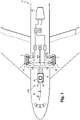
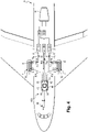
- the hydraulic braking device is mounted in an aircraft A comprising a landing gear which comprises a first wheel R1 and a second wheel R2.
- Aircraft A further comprises a turbine 90 connected to one of the engines of aircraft A.
- the device 100 comprises a first servo valve 10, a second servo valve 20 and a third servo valve 30 electrically controlled.
- the device 100 also comprises a first brake 1 of the first wheel R1 and a second brake 2 of the second wheel R2.
- the first brake 1 comprises a first stack 4 of braking discs which comes press a first brake actuator 5.1 and a second brake actuator 5.2 in a manner known to those skilled in the art.
- the second brake 2 comprises a second stack 6 of brake discs which is pressed by a third brake actuator 7.1 and a fourth brake actuator 7.2 in a manner known to those skilled in the art.
- the turbine 90 drives a first hydraulic unit 91 and a second hydraulic unit 92.
- the first servovalve 10 is powered by the first hydraulic unit 91 and has an output connected to the first actuator 5.1 to deliver a fluid to it at a first pressure P10.
- the second servo valve 20 is powered by the first hydraulic unit 91 and has an output connected to the third actuator 7.1 to deliver fluid to it at a second pressure P20.
- the third servo valve 30 is powered by the second hydraulic unit 92 and has outputs connected respectively to the second actuator 5.2 and to the fourth actuator 7.2 to deliver thereto a fluid at a third pressure P30.
- the device 100 also comprises a first braking torque sensor 8 arranged on the first brake 1 to provide a first measurement (here a first intensity I8) representative of a first braking torque C1 applied by the first brake 1 on the first wheel R1.
- a second braking torque sensor 9 is arranged on the second brake 2 to provide a second measurement (here a second intensity I9) of a second braking torque C2 applied by the second brake 2 to the second wheel R2.
- a control unit 40 comprising in known manner a microprocessor 41, is connected to the first servo valve 10, to the second servo valve 20, to the third servo valve 30, to the first sensor 8 as well as to the second sensor 9.
- the device 100 also comprises a brake pedal 42 which can be actuated by a pilot of the aircraft A and which delivers a braking torque instruction If to the control unit 40.
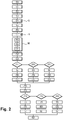
- a step 50 the pilot of the aircraft A acts on the brake pedal 42 and the control unit 40 receives a braking torque instruction If corresponding to the depression of the brake pedal 42.
- the control unit 40 on the basis of the braking torque instruction If, establishes a first braking torque setpoint Cf1 for the first brake 1 and a second braking torque setpoint Cf2 for the second brake 2
- the first braking torque setpoint Cf1 and the second braking torque setpoint Cf2 are, here, both equal to 3500 decaNewton meters.
- the control unit 40 measures the first intensity I8 supplied by the first torque sensor 8 and converts this first intensity 18 into a value of first braking torque C1app applied by the first brake 1 to the first wheel R1 . According to a step 53, the control unit 40 then determines a first torque error ⁇ 1 that exists between the first braking setpoint Cf1 and the first applied braking torque C1app.
- the unit 40 defines a first average pressure supply P1 to be applied to the first brake 1 to obtain a first applied braking torque C1app equal to the first torque setpoint Cf1 using a first servo loop 43 known in itself.
- the first servo loop 93 includes a PID regulator.
- This first mean supply pressure P1 is here equal to 100,000 hectopascals.
- the average feed pressure is determined in a manner known per se by those skilled in the art. The numerical values are given for information only.
- the control unit measures the second intensity 19 supplied by the second torque sensor 9, converts this second intensity 19 into a second braking torque value C2app applied by the second brake 2 to the second wheel R2.
- the control unit 40 determines a second torque error ⁇ 2 that exists between the second braking setpoint Cf2 and the second applied braking torque C2app.
- the unit 40 defines a second average supply pressure P2 to be applied to the second brake 2 to obtain a second applied braking torque C2app equal to the second torque setpoint Cf2 using a second servo loop 94 known in itself .
- the second servo loop 44 comprises a PID regulator.
- This second average supply pressure P2 is here equal to 150,000 hectopascals.
- the control unit 40 defines - on the basis of the first average supply pressure P1 and the second average supply pressure P2 - a first pressure setpoint Cp1, a second pressure setpoint Cp2 and a third pressure setpoint Cp3.
- Step 58 includes several operations.
- the control unit 40 during a first operation 59, establishes the value of the third pressure set point Cp3 at a value equal to the arithmetic mean of the first mean supply pressure P1 and the second average supply pressure P2, being 125,000 hectopascals.
- Cp1 is the value of the first pressure setpoint
- P1 is the value of the first average supply pressure
- Cp3 is the value of the third pressure setpoint.
- the first pressure setpoint Cp1 is equal to 75000 hectopascals.
- Cp2 is the value of the second pressure setpoint
- P2 is the value of the second average supply pressure
- Cp3 is the value of the third pressure setpoint.
- the second pressure setpoint Cp2 is equal to 175,000 hectopascals.
- the control unit 40 compares the value of the first pressure setpoint Cp1 with a first threshold top Pmax10 -here equal to 200,000 hectopascals- and which corresponds to the first maximum output pressure that the first servovalve 10 can deliver.
- the control unit 40 compares the value of the first pressure setpoint Cp1 with a first low threshold Pmin10 -here equal to 0 hectopascal- and which corresponds to the first minimum output pressure that the first servovalve can deliver. 10.
- the control unit 40 compares the value of the second pressure setpoint Cp2 with a second low threshold Pmin20 -here equal to 0 hectopascal- and which corresponds to the second minimum output pressure that the second servovalve can deliver. 20.
- the control unit 40 applies the first pressure setpoint Cp1 to the first servovalve 10, the second pressure setpoint Cp2 to the second servovalve 20 and the third pressure setpoint Cp3 to the third servovalve 30.
- the control unit 40 monitors the evolution of the first pressure setpoint Cp1, of the second pressure setpoint Cp2 and of the third pressure setpoint Cp3 and limits, according to a step 83 located between steps 73/77/97 and step 82, the rate of increase of the first pressure setpoint Cp1, of the second pressure setpoint Cp2 and of the third pressure setpoint Cp3 so that the rate of increase of the pressure setpoints remains below 100,000 hectopascals per second.
- the device 100 also comprises a first pressure sensor 11 arranged on the outlet 12 of the first servovalve 10 to provide a first measurement of the first pressure P10 at the outlet of the first servovalve 10.
- the device 100 also comprises a second pressure sensor 21 disposed on the output 22 of the second servo valve 20 to provide a second measurement of the second pressure P20 at the output of the second servo valve 20.
- the device 100 also comprises a third pressure sensor 31 disposed on the output 32 of the third servovalve 30 to provide a third measurement of the third pressure P30 at the output of the third servovalve 30.
- the control unit 40 measures a third intensity I11 supplied by the first pressure sensor 11, converts this third intensity I11 into a first pressure value P10 and defines a value of a first command -here a first voltage U13- to be applied to the first servovalve 10 as a function of the value of the third intensity I11 and of the first pressure setpoint Cp1 using a third loop of enslavement known in itself.
- the third servo loop includes a PID controller.
- the control unit 40 measures a fourth intensity I21 supplied by the second pressure sensor 21, converts this fourth intensity I21 into a second pressure value P20 and sets a value of a second control -here a second voltage U23- to be applied to the second servovalve 20 as a function of the fourth intensity I21 and of the second pressure setpoint Cp2 using a fourth control loop known in itself.
- the fourth servo loop includes a PID controller.
- the control unit 40 measures a fifth intensity I31 supplied by the third pressure sensor 31, converts this fifth intensity I31 into a third pressure value P30 and defines a value of a third command -here a third voltage U23- to be applied to the second servovalve 20 as a function of the fifth intensity value I31 and of the third pressure set point Cp3 using a fifth d loop servo 47 known in itself.
- the fifth servo loop 47 comprises a PID regulator.
- the operation 55 to establish the value of the third pressure setpoint Cp3 is carried out by setting the third pressure setpoint Cp3 to a value corresponding to the smallest value among the first supply pressure P1 and the second supply pressure P2.
- the operation 55 to establish the value of the third pressure setpoint Cp3 is carried out by setting the third pressure setpoint Cp3 to a value corresponding to the greatest value among the first supply pressure P1 and the second supply pressure P2.
Landscapes
- Engineering & Computer Science (AREA)
- Mechanical Engineering (AREA)
- Transportation (AREA)
- Aviation & Aerospace Engineering (AREA)
- General Engineering & Computer Science (AREA)
- Valves And Accessory Devices For Braking Systems (AREA)
- Regulating Braking Force (AREA)
- Braking Arrangements (AREA)
- Braking Systems And Boosters (AREA)
Claims (14)
- Verfahren zum Steuern einer hydraulischen Bremsvorrichtung (100), wobei die Bremsvorrichtung (100) umfasst- ein erstes Servoventil (10), ein zweites Servoventil (20), ein drittes Servoventil (30);- eine erste Bremse (1) eines ersten Rades (R1), die mindestens einen ersten Bremsaktor (5.1) und einen zweiten Bremsaktor (5.2) umfasst, um ein erstes Bremsmoment (C1) auf das erste Rad (R1) aufzubringen;- eine zweite Bremse (2) eines zweiten Rades (R2), die mindestens einen dritten Bremsaktor (7.1) und einen vierten Bremsaktor (7.2) umfasst, um ein zweites Bremsmoment (C2) auf das zweite Rad (R2) aufzubringen;bei dem das erste Servoventil (10) ausgebildet ist, um einen ersten Druck (P10) an den ersten Aktor (5.1) zu liefern, das zweite Servoventil (20) ausgebildet ist, um einen zweiten Druck (P20) an den dritten Aktor (7.1) zu liefern, das dritte Servoventil (30) ausgebildet ist, um einen dritten Druck (P30) an den zweiten Aktor (5.2) und an den vierten Aktor (7.2) zu liefern;wobei das Verfahren die folgenden Schritte umfasst:- Empfangen einer Bremsmomentanweisung (If);- auf der Grundlage der empfangenen Bremsmomentanweisung (If), Festlegen eines ersten Bremsmomentsollwerts (Cf1) für die erste Bremse (1) und eines zweiten Bremsmomentsollwerts (Cf2) für die zweite Bremse (2);- Messen eines ersten Werts eines ersten Parameters (I8), der repräsentativ für das erste Bremsmoment (C1) ist;- Definieren eines ersten mittleren Versorgungsdrucks (P1) zum Aufbringen auf die erste Bremse (1) in Abhängigkeit von dem ersten Wert des ersten Parameters und des ersten Bremssollwerts (Cf1) mit Hilfe eines ersten Regelkreises (93);- Messen eines zweiten Werts eines zweiten Parameters (I9), der repräsentativ für das zweite Bremsmoment (C2) ist;- Definieren eines zweiten mittleren Versorgungsdrucks (P2) zum Aufbringen auf die zweite Bremse (2) in Abhängigkeit von dem zweiten Wert des zweiten Parameters und des zweiten Bremssollwerts (Cf2) mit Hilfe eines zweiten Regelkreises (94);- auf der Grundlage des ersten mittleren Versorgungsdrucks (P1) und des zweiten mittleren Versorgungsdrucks (P2), Definieren eines ersten Drucksollwerts (Cp1), eines zweiten Drucksollwerts (Cp2) und eines dritten Drucksollwerts (Cp3);- Aufbringen des ersten Drucksollwerts (Cp1) auf das erste Servoventil (10), des zweiten Drucksollwerts (Cp2) auf das zweite Servoventil (20) und des dritten Drucksollwerts (Cp3) auf das dritte Servoventil (30).
- Verfahren nach Anspruch 1, umfassend den zusätzlichen Schritt des Begrenzens der Steigerungsgeschwindigkeit des ersten Drucksollwerts (Cp1) und/oder des zweiten Drucksollwerts (Cp2) und/oder des dritten Drucksollwerts (Cp3).
- Verfahren nach einem der vorhergehenden Ansprüche, bei dem der Schritt des Definierens eines ersten Drucksollwerts (Cp1), eines zweiten Drucksollwerts (Cp2) und eines dritten Drucksollwerts (Cp3) die folgenden Vorgänge umfasst:- Definieren eines Werts für den ersten mittleren Versorgungsdruck (P1) der ersten Bremse (1);- Definieren eines Werts für den zweiten mittleren Versorgungsdruck (P2) der zweiten Bremse (2);- Festlegen des Werts für den dritten Drucksollwert (Cp3);- Festlegen des Werts für den ersten Drucksollwert (Cp1) auf einen Wert gleich:
 - Festlegen des Werts des zweiten Drucksollwerts (Cp2) auf einen Wert gleich:
- Verfahren nach Anspruch 3, bei dem der Wert des dritten Drucksollwerts (Cp3) auf einen Wert festgelegt wird, der dem arithmetischen Mittel des ersten mittleren Versorgungsdrucks (P1) und des zweiten mittleren Versorgungsdrucks (P2) entspricht.
- Verfahren nach Anspruch 3, bei dem der Wert des dritten Drucksollwerts (Cp3) auf einen Wert festgelegt wird, der dem kleinsten Wert unter dem ersten mittleren Versorgungsdruck (P1) und dem zweiten mittleren Versorgungsdruck (P2) entspricht.
- Verfahren nach Anspruch 3, bei dem der Wert des dritten Drucksollwerts (Cp3) auf den höchsten Wert unter dem ersten mittleren Versorgungsdruck (P1) und dem zweiten mittleren Versorgungsdruck (P2) festgelegt wird.
- Verfahren nach einem der vorhergehenden Ansprüche, bei dem nach dem Schritt des Definierens eines ersten Drucksollwerts (Cp1), eines zweiten Drucksollwerts (Cp2) und eines dritten Drucksollwerts (Cp3) und vor dem Schritt des Aufbringens des ersten Drucksollwerts (Cp1) auf das erste Servoventil (10), des zweiten Drucksollwerts (Cp2) auf das zweite Servoventil (20) und des dritten Drucksollwerts (Cp3) auf das dritte Servoventil (30) das Verfahren die folgenden zusätzlichen Schritte umfasst:- Vergleichen des Werts des ersten Drucksollwerts (Cp1) mit einem ersten hohen Schwellenwert (Pmax10);- Vergleichen des Werts des zweiten Drucksollwerts (Cp2) mit einem zweiten hohen Schwellenwert (Pmax20);- wenn der Wert des ersten Drucksollwerts (Cp1) größer oder gleich dem ersten hohen Schwellenwert (Pmax10) ist und wenn der Wert des zweiten Drucksollwerts (Cp2) größer oder gleich dem zweiten hohen Schwellenwert (Pmax20) ist:- Festlegen des Werts des ersten Drucksollwerts (Cp1) auf den ersten hohen Schwellenwert (Pmax10);- Festlegen des Werts des zweiten Drucksollwerts (Cp2) auf den zweiten hohen Schwellenwert (Pmax20); und- Festlegen des Werts des dritten Drucksollwerts (Cp3) auf einen dritten hohen Schwellenwert (Pmax30).
- Verfahren nach einem der vorhergehenden Ansprüche, bei dem nach dem Schritt des Definierens eines ersten Drucksollwerts (Cp1), eines zweiten Drucksollwerts (Cp2) und eines dritten Drucksollwerts (Cp3) und vor dem Schritt des Aufbringens des ersten Drucksollwerts (Cp1) auf das erste Servoventil (10), des zweiten Drucksollwerts (Cp2) auf das zweite Servoventil (20) und des dritten Drucksollwerts (Cp3) auf das dritte Servoventil (30), wobei das Verfahren die folgenden zusätzlichen Schritte umfasst:- wenn der Wert des ersten Drucksollwerts (Cp1) größer oder gleich einem ersten hohen Schwellenwert (Pmax10) ist und wenn der Wert des zweiten Drucksollwerts (Cp2) kleiner als ein zweiter hoher Schwellenwert (Pmax20) ist:- Festlegen des Werts des ersten Drucksollwerts (CP1) auf den ersten hohen Schwellenwert (Pmax10);- Festlegen des Werts des dritten Drucksollwerts (Cp3) auf einen Wert gleich:
 - Festlegen des Werts des zweiten Drucksollwerts (Cp2) auf einen Wert gleich:
- Verfahren nach einem der vorhergehenden Ansprüche, bei dem nach dem Schritt des Definierens eines ersten Drucksollwerts (Cp1), eines zweiten Drucksollwerts (Cp2) und eines dritten Drucksollwerts (Cp3) und vor dem Schritt des Aufbringens des ersten Drucksollwerts (Cp1) auf das erste Servoventil (10), des zweiten Drucksollwerts (Cp2) auf das zweite Servoventil (20) und des dritten Drucksollwerts (Cp3) auf das dritte Servoventil (30) das Verfahren die folgenden zusätzlichen Schritte umfasst:- Vergleichen des Werts des ersten Drucksollwerts (Cp1) mit einem ersten niedrigen Schwellenwert (Pmin10);- Vergleichen des Werts des zweiten Drucksollwerts (Cp2) mit einem zweiten niedrigen Schwellenwert (Pmin20);- wenn der Wert des ersten Drucksollwerts (Cp1) kleiner oder gleich dem ersten niedrigen Schwellenwert (Pmin10) ist und wenn der Wert des zweiten Drucksollwerts (Cp2) kleiner oder gleich dem zweiten niedrigen Schwellenwert (Pmin20) ist:- Festlegen des Werts des ersten Drucksollwerts (Cp1) auf den ersten niedrigen Schwellenwert (Pmin10); und- Festlegen des Werts des zweiten Drucksollwerts (Cp2) auf den zweiten niedrigen Schwellenwert (Pmin20); und- Festlegen des Werts des dritten Drucksollwerts (Cp3) auf einen dritten niedrigen Schwellenwert (Pmin30).
- Verfahren nach einem der vorhergehenden Ansprüche, bei dem nach dem Schritt des Definierens eines ersten Drucksollwerts (Cp1), eines zweiten Drucksollwerts (Cp2) und eines dritten Drucksollwerts (Cp3) und vor dem Schritt des Aufbringens des ersten Drucksollwerts (Cp1) auf das erste Servoventil (10), des zweiten Drucksollwerts (Cp2) auf das zweite Servoventil (20) und des dritten Drucksollwerts (Cp3) auf das dritte Servoventil (30) das Verfahren die folgenden zusätzlichen Schritte umfasst:- wenn der Wert des ersten Drucksollwerts (Cp1) kleiner oder gleich einem ersten niedrigen Schwellenwert (Pmin10) ist und wenn der Wert des zweiten Versorgungssollwerts größer als ein zweiter niedriger Schwellenwert (Pmin20) ist;- Festlegen des Werts des ersten Drucksollwerts (Cp1) auf den ersten niedrigen Schwellenwert (Pmin10);- Festlegen des Werts des dritten Drucksollwerts (Cp3) auf einen Wert gleich:
 - Festlegen des Werts des zweiten Drucksollwerts (Cp2) auf einen Wert gleich:
- Verfahren nach einem der vorhergehenden Ansprüche, umfassend die folgenden zusätzlichen Schritte:- Messen eines dritten Werts (I11), der repräsentativ für den ersten Druck (P10) ist;- Definieren eines ersten Befehls zum Aufbringen auf das erste Servoventil (10) in Abhängigkeit von dem dritten Wert (I11) und dem ersten Drucksollwert (Cp1) mit Hilfe eines dritten Regelkreises (95);- Messen eines vierten Werts (I21), der repräsentativ für den zweiten Druck (P20) ist;- Definieren eines zweiten Befehls zum Aufbringen auf das zweite Servoventil in Abhängigkeit von dem vierten Wert (I21) und dem zweiten Drucksollwert (Cp2) mit Hilfe eines vierten Regelkreises (96);- Messen eines fünften Werts (I31), der repräsentativ für den dritten Druck (P30) ist;- Definieren eines dritten Befehls zum Aufbringen auf das zweite Servoventil in Abhängigkeit von dem fünften Wert (I31) und dem dritten Drucksollwert (Cp3) mit Hilfe eines fünften Regelkreises (97).
- Bremsvorrichtung (100), umfassend:- ein erstes Servoventil (10), ein zweites Servoventil (20), ein drittes Servoventil (30);- eine erste Bremse (1) eines ersten Rades (R1), die einen ersten Bremsaktor (5.1) und einen zweiten Bremsaktor (5.2) umfasst;- eine zweite Bremse (2) eines zweiten Rades (R2), die einen dritten Bremsaktor (7.1) und einen vierten Bremsaktor (7.2) umfasst;- wobei das erste Servoventil (10) ausgebildet ist, um einen ersten Druck (P10) an den ersten Aktor (5.1) zu liefern, wobei das zweite Servoventil (20) ausgebildet ist, um einen zweiten Druck (P20) an den dritten Aktor (7.1) zu liefern; wobei die Vorrichtung (100) ferner umfasst:- einen ersten Bremsmomentsensor (8), der an der ersten Bremse (1) angeordnet ist, um eine erste Messung eines ersten Bremsmoments (C1) zu liefern, das von der ersten Bremse (1) auf das erste Rad (R1) aufgebracht wird;- einen zweiten Bremsmomentsensor (9), der an der zweiten Bremse (2) angeordnet ist, um eine zweite Messung eines zweiten Bremsmoments (C2) zu liefern, das von der zweiten Bremse (2) auf das zweite Rad (R2) aufgebracht wird;- eine Steuereinheit (40), die mit dem ersten Servoventil (10), dem zweiten Servoventil (20), dem dritten Servoventil (30), dem ersten Bremsmomentsensor (8) und dem zweiten Bremsmomentsensor (9) verbunden ist;- eine Bremssteuerschnittstelle (42), die ausgebildet ist, um eine Bremsmomentanweisung (If) an die Steuereinheit (40) zu liefern;dadurch gekennzeichnet, dass:- das dritte Servoventil ausgebildet ist, um einen dritten Druck (P30) an den zweiten Aktor (5.2) und an den vierten Aktor (7.2) zu liefern; und dassdie Steuereinheit (40) ausgebildet ist, um das Verfahren nach einem der Ansprüche 1 bis 10 durchzuführen.
- Bremsvorrichtung (100) nach Anspruch 12, umfassend- einen ersten Drucksensor (11), der an einem ersten Ausgang (12) des ersten Servoventils (10) angeordnet ist, um eine erste Messung eines ersten Drucks (P10) eines Fluids am Ausgang des ersten Servoventils (10) zu liefern;- einen zweiten Drucksensor (21), der an einem zweiten Ausgang (22) des zweiten Servoventils (20) angeordnet ist, um eine zweite Messung eines zweiten Drucks (P20) eines Fluids am Ausgang des zweiten Servoventils (20) zu liefern;- einen dritten Drucksensor (31), der an einem dritten Ausgang (32) des dritten Servoventils (30) angeordnet ist, um eine dritte Messung eines dritten Drucks (P30) eines Fluids am Ausgang des dritten Servoventils (30) zu liefern;wobei die Steuereinheit (40) ausgebildet ist, um das Verfahren nach Anspruch 11 durchzuführen.
- Luftfahrzeug (A), umfassend eine Bremsvorrichtung (100) nach Anspruch 12 oder 13.
Applications Claiming Priority (1)
| Application Number | Priority Date | Filing Date | Title |
|---|---|---|---|
| FR1903701A FR3094695B1 (fr) | 2019-04-05 | 2019-04-05 | Procédé de pilotage d’un dispositif de freinage |
Publications (2)
| Publication Number | Publication Date |
|---|---|
| EP3718883A1 EP3718883A1 (de) | 2020-10-07 |
| EP3718883B1 true EP3718883B1 (de) | 2022-07-13 |
Family
ID=68138215
Family Applications (1)
| Application Number | Title | Priority Date | Filing Date |
|---|---|---|---|
| EP20168029.5A Active EP3718883B1 (de) | 2019-04-05 | 2020-04-03 | Steuerverfahren einer bremsvorrichtung |
Country Status (6)
| Country | Link |
|---|---|
| US (1) | US11618421B2 (de) |
| EP (1) | EP3718883B1 (de) |
| CN (1) | CN111792025B (de) |
| CA (1) | CA3077780C (de) |
| ES (1) | ES2926899T3 (de) |
| FR (1) | FR3094695B1 (de) |
Cited By (1)
| Publication number | Priority date | Publication date | Assignee | Title |
|---|---|---|---|---|
| FR3164446A1 (fr) * | 2024-07-15 | 2026-01-16 | Safran Landing Systems | Procédé de commande pour réduire le temps de remplissage d’un frein sur un système de freinage hydraulique d’un train d’atterrissage d’un aéronef |
Families Citing this family (4)
| Publication number | Priority date | Publication date | Assignee | Title |
|---|---|---|---|---|
| US11499880B2 (en) * | 2020-08-03 | 2022-11-15 | Fisher Controls International Llc | Methods and apparatus for pressure-based direct measurement of a final control element variable |
| US12194974B2 (en) * | 2020-08-20 | 2025-01-14 | Goodrich Corporation | Systems and methods for pressure control mixed mode for braking operation |
| US11975704B2 (en) | 2021-01-05 | 2024-05-07 | The Boeing Company | Fault-tolerant brake load alleviation |
| ES3031839T3 (en) * | 2021-05-06 | 2025-07-11 | Safran Landing Systems Uk Ltd | Anti-lock braking system |
Citations (1)
| Publication number | Priority date | Publication date | Assignee | Title |
|---|---|---|---|---|
| DE4227157C2 (de) * | 1991-09-02 | 1994-11-24 | Deutsche Aerospace Airbus | Schaltungsanordnung für ein automatisches Bremssteuersystem |
Family Cites Families (11)
| Publication number | Priority date | Publication date | Assignee | Title |
|---|---|---|---|---|
| US3718377A (en) * | 1971-09-30 | 1973-02-27 | Gen Motors Corp | Hydraulic vehicle ground speed computer |
| US3720447A (en) * | 1971-09-30 | 1973-03-13 | Gen Motors Corp | Hydraulic anti-lock brake control system |
| DE4214182C2 (de) * | 1992-04-30 | 1995-12-07 | Daimler Benz Ag | Bremsdrucksteuereinrichtung zur Bremsbelagverschleißoptimierung in einem Kraftfahrzeug |
| US5456523A (en) * | 1994-01-19 | 1995-10-10 | Mcdonnell Douglas Corporation | Multi-wheel brake system |
| JP3851779B2 (ja) * | 1999-05-14 | 2006-11-29 | ハイドロ エアー インコーポレイテッド | 二重冗長能動/能動ブレーキ・バイ・ワイヤ技術 |
| FR2973761B1 (fr) * | 2011-04-05 | 2013-04-05 | Messier Bugatti | Procede de repartition de couple de freinage entre des roues freinees portees par au moins un atterrisseur d'un aeronef. |
| JP6091841B2 (ja) * | 2012-10-25 | 2017-03-08 | Ntn株式会社 | パーキング機能付き電動ブレーキアクチュエータ |
| FR3061139B1 (fr) * | 2016-12-23 | 2019-05-31 | Safran Landing Systems | Architecture de systeme de freinage pour aeronef |
| US10518758B2 (en) * | 2017-04-18 | 2019-12-31 | Goodrich Corporation | Emergency park brake system |
| US10300897B2 (en) * | 2017-05-15 | 2019-05-28 | Goodrich Corporation | Brake load balance and runway centering techniques |
| CN208615936U (zh) * | 2018-05-07 | 2019-03-19 | 西安航空制动科技有限公司 | 一种飞机液压刹车系统压力调节器 |
-
2019
- 2019-04-05 FR FR1903701A patent/FR3094695B1/fr active Active
-
2020
- 2020-04-02 CA CA3077780A patent/CA3077780C/fr active Active
- 2020-04-03 EP EP20168029.5A patent/EP3718883B1/de active Active
- 2020-04-03 US US16/839,621 patent/US11618421B2/en active Active
- 2020-04-03 ES ES20168029T patent/ES2926899T3/es active Active
- 2020-04-07 CN CN202010263968.9A patent/CN111792025B/zh active Active
Patent Citations (1)
| Publication number | Priority date | Publication date | Assignee | Title |
|---|---|---|---|---|
| DE4227157C2 (de) * | 1991-09-02 | 1994-11-24 | Deutsche Aerospace Airbus | Schaltungsanordnung für ein automatisches Bremssteuersystem |
Cited By (2)
| Publication number | Priority date | Publication date | Assignee | Title |
|---|---|---|---|---|
| FR3164446A1 (fr) * | 2024-07-15 | 2026-01-16 | Safran Landing Systems | Procédé de commande pour réduire le temps de remplissage d’un frein sur un système de freinage hydraulique d’un train d’atterrissage d’un aéronef |
| WO2026017940A1 (fr) * | 2024-07-15 | 2026-01-22 | Safran Landing Systems | Procédé de commande pour réduire le temps de remplissage d'un frein sur un système de freinage hydraulique d'un train d'atterrissage d'un aéronef |
Also Published As
| Publication number | Publication date |
|---|---|
| FR3094695A1 (fr) | 2020-10-09 |
| EP3718883A1 (de) | 2020-10-07 |
| CA3077780A1 (fr) | 2020-10-05 |
| US20200317171A1 (en) | 2020-10-08 |
| CA3077780C (fr) | 2022-07-12 |
| US11618421B2 (en) | 2023-04-04 |
| CN111792025A (zh) | 2020-10-20 |
| FR3094695B1 (fr) | 2021-08-13 |
| CN111792025B (zh) | 2024-08-16 |
| ES2926899T3 (es) | 2022-10-31 |
Similar Documents
| Publication | Publication Date | Title |
|---|---|---|
| EP3718883B1 (de) | Steuerverfahren einer bremsvorrichtung | |
| EP3109155B1 (de) | Regulierverfahren für eine dreimotorige antriebsanlage für ein drehflügelflugzeug | |
| EP1240417B1 (de) | Verfahren und vorrichtung zur leistungsregelung einer hubschrauber-rotor-antriebseinheit | |
| EP2719592A1 (de) | Aufbau eines elektromechanischen Bremssystems | |
| EP2886454A1 (de) | Verfahren zur Steuerung eines Elektromotors mit Drehantrieb eines Luftfahrzeugrads | |
| EP1586968B1 (de) | System zur längsgerichteten Führung eines am Boden rollenden Flugzeuges | |
| EP3718841B1 (de) | Bremssystem eines luftfahrzeugrads, das gemäss normal-modus oder rto-modus eingestellt werden kann | |
| CA3112147C (fr) | Procede de commande d'un helicoptere hybride lors d'une panne d'une installation motrice | |
| FR3008368A1 (fr) | Procede de gestion du freinage d'un aeronef | |
| EP4054906B1 (de) | Flugzeugbremsverfahren mit dynamischer korrektur des bremsbefehls | |
| EP3666647B1 (de) | Verfahren zur drehmomentregelung einer drehantriebsvorrichtung der räder eines luftfahrzeugs | |
| EP4308830B1 (de) | System und verfahren zur verbesserten traktionssteuerung | |
| EP3868658B1 (de) | Verfahren zur steuerung eines hybrid-helikopters im falle eines ausfalls einer antriebsanlage | |
| EP4103469B1 (de) | Verfahren zur steuerung eines flugzeugrollsystems | |
| FR2873977A1 (fr) | Procede de commande d'un vehicule au moyen d'un dispositif de freinage pilotable | |
| EP4662097A1 (de) | Selektives bremsen auf rädern ohne antriebsaktuator |
Legal Events
| Date | Code | Title | Description |
|---|---|---|---|
| PUAI | Public reference made under article 153(3) epc to a published international application that has entered the european phase |
Free format text: ORIGINAL CODE: 0009012 |
|
| STAA | Information on the status of an ep patent application or granted ep patent |
Free format text: STATUS: THE APPLICATION HAS BEEN PUBLISHED |
|
| AK | Designated contracting states |
Kind code of ref document: A1 Designated state(s): AL AT BE BG CH CY CZ DE DK EE ES FI FR GB GR HR HU IE IS IT LI LT LU LV MC MK MT NL NO PL PT RO RS SE SI SK SM TR |
|
| AX | Request for extension of the european patent |
Extension state: BA ME |
|
| STAA | Information on the status of an ep patent application or granted ep patent |
Free format text: STATUS: REQUEST FOR EXAMINATION WAS MADE |
|
| 17P | Request for examination filed |
Effective date: 20210325 |
|
| RBV | Designated contracting states (corrected) |
Designated state(s): AL AT BE BG CH CY CZ DE DK EE ES FI FR GB GR HR HU IE IS IT LI LT LU LV MC MK MT NL NO PL PT RO RS SE SI SK SM TR |
|
| GRAP | Despatch of communication of intention to grant a patent |
Free format text: ORIGINAL CODE: EPIDOSNIGR1 |
|
| STAA | Information on the status of an ep patent application or granted ep patent |
Free format text: STATUS: GRANT OF PATENT IS INTENDED |
|
| INTG | Intention to grant announced |
Effective date: 20220201 |
|
| GRAS | Grant fee paid |
Free format text: ORIGINAL CODE: EPIDOSNIGR3 |
|
| GRAA | (expected) grant |
Free format text: ORIGINAL CODE: 0009210 |
|
| STAA | Information on the status of an ep patent application or granted ep patent |
Free format text: STATUS: THE PATENT HAS BEEN GRANTED |
|
| AK | Designated contracting states |
Kind code of ref document: B1 Designated state(s): AL AT BE BG CH CY CZ DE DK EE ES FI FR GB GR HR HU IE IS IT LI LT LU LV MC MK MT NL NO PL PT RO RS SE SI SK SM TR |
|
| REG | Reference to a national code |
Ref country code: CH Ref legal event code: EP |
|
| REG | Reference to a national code |
Ref country code: DE Ref legal event code: R096 Ref document number: 602020003953 Country of ref document: DE |
|
| REG | Reference to a national code |
Ref country code: AT Ref legal event code: REF Ref document number: 1504157 Country of ref document: AT Kind code of ref document: T Effective date: 20220815 |
|
| REG | Reference to a national code |
Ref country code: IE Ref legal event code: FG4D Free format text: LANGUAGE OF EP DOCUMENT: FRENCH |
|
| REG | Reference to a national code |
Ref country code: SE Ref legal event code: TRGR |
|
| REG | Reference to a national code |
Ref country code: ES Ref legal event code: FG2A Ref document number: 2926899 Country of ref document: ES Kind code of ref document: T3 Effective date: 20221031 |
|
| REG | Reference to a national code |
Ref country code: LT Ref legal event code: MG9D |
|
| REG | Reference to a national code |
Ref country code: NL Ref legal event code: MP Effective date: 20220713 |
|
| PG25 | Lapsed in a contracting state [announced via postgrant information from national office to epo] |
Ref country code: RS Free format text: LAPSE BECAUSE OF FAILURE TO SUBMIT A TRANSLATION OF THE DESCRIPTION OR TO PAY THE FEE WITHIN THE PRESCRIBED TIME-LIMIT Effective date: 20220713 Ref country code: PT Free format text: LAPSE BECAUSE OF FAILURE TO SUBMIT A TRANSLATION OF THE DESCRIPTION OR TO PAY THE FEE WITHIN THE PRESCRIBED TIME-LIMIT Effective date: 20221114 Ref country code: NO Free format text: LAPSE BECAUSE OF FAILURE TO SUBMIT A TRANSLATION OF THE DESCRIPTION OR TO PAY THE FEE WITHIN THE PRESCRIBED TIME-LIMIT Effective date: 20221013 Ref country code: NL Free format text: LAPSE BECAUSE OF FAILURE TO SUBMIT A TRANSLATION OF THE DESCRIPTION OR TO PAY THE FEE WITHIN THE PRESCRIBED TIME-LIMIT Effective date: 20220713 Ref country code: LV Free format text: LAPSE BECAUSE OF FAILURE TO SUBMIT A TRANSLATION OF THE DESCRIPTION OR TO PAY THE FEE WITHIN THE PRESCRIBED TIME-LIMIT Effective date: 20220713 Ref country code: LT Free format text: LAPSE BECAUSE OF FAILURE TO SUBMIT A TRANSLATION OF THE DESCRIPTION OR TO PAY THE FEE WITHIN THE PRESCRIBED TIME-LIMIT Effective date: 20220713 Ref country code: FI Free format text: LAPSE BECAUSE OF FAILURE TO SUBMIT A TRANSLATION OF THE DESCRIPTION OR TO PAY THE FEE WITHIN THE PRESCRIBED TIME-LIMIT Effective date: 20220713 |
|
| REG | Reference to a national code |
Ref country code: AT Ref legal event code: MK05 Ref document number: 1504157 Country of ref document: AT Kind code of ref document: T Effective date: 20220713 |
|
| PG25 | Lapsed in a contracting state [announced via postgrant information from national office to epo] |
Ref country code: PL Free format text: LAPSE BECAUSE OF FAILURE TO SUBMIT A TRANSLATION OF THE DESCRIPTION OR TO PAY THE FEE WITHIN THE PRESCRIBED TIME-LIMIT Effective date: 20220713 Ref country code: IS Free format text: LAPSE BECAUSE OF FAILURE TO SUBMIT A TRANSLATION OF THE DESCRIPTION OR TO PAY THE FEE WITHIN THE PRESCRIBED TIME-LIMIT Effective date: 20221113 Ref country code: HR Free format text: LAPSE BECAUSE OF FAILURE TO SUBMIT A TRANSLATION OF THE DESCRIPTION OR TO PAY THE FEE WITHIN THE PRESCRIBED TIME-LIMIT Effective date: 20220713 Ref country code: GR Free format text: LAPSE BECAUSE OF FAILURE TO SUBMIT A TRANSLATION OF THE DESCRIPTION OR TO PAY THE FEE WITHIN THE PRESCRIBED TIME-LIMIT Effective date: 20221014 |
|
| REG | Reference to a national code |
Ref country code: DE Ref legal event code: R097 Ref document number: 602020003953 Country of ref document: DE |
|
| PG25 | Lapsed in a contracting state [announced via postgrant information from national office to epo] |
Ref country code: SM Free format text: LAPSE BECAUSE OF FAILURE TO SUBMIT A TRANSLATION OF THE DESCRIPTION OR TO PAY THE FEE WITHIN THE PRESCRIBED TIME-LIMIT Effective date: 20220713 Ref country code: RO Free format text: LAPSE BECAUSE OF FAILURE TO SUBMIT A TRANSLATION OF THE DESCRIPTION OR TO PAY THE FEE WITHIN THE PRESCRIBED TIME-LIMIT Effective date: 20220713 Ref country code: DK Free format text: LAPSE BECAUSE OF FAILURE TO SUBMIT A TRANSLATION OF THE DESCRIPTION OR TO PAY THE FEE WITHIN THE PRESCRIBED TIME-LIMIT Effective date: 20220713 Ref country code: CZ Free format text: LAPSE BECAUSE OF FAILURE TO SUBMIT A TRANSLATION OF THE DESCRIPTION OR TO PAY THE FEE WITHIN THE PRESCRIBED TIME-LIMIT Effective date: 20220713 Ref country code: AT Free format text: LAPSE BECAUSE OF FAILURE TO SUBMIT A TRANSLATION OF THE DESCRIPTION OR TO PAY THE FEE WITHIN THE PRESCRIBED TIME-LIMIT Effective date: 20220713 |
|
| PLBE | No opposition filed within time limit |
Free format text: ORIGINAL CODE: 0009261 |
|
| STAA | Information on the status of an ep patent application or granted ep patent |
Free format text: STATUS: NO OPPOSITION FILED WITHIN TIME LIMIT |
|
| PG25 | Lapsed in a contracting state [announced via postgrant information from national office to epo] |
Ref country code: SK Free format text: LAPSE BECAUSE OF FAILURE TO SUBMIT A TRANSLATION OF THE DESCRIPTION OR TO PAY THE FEE WITHIN THE PRESCRIBED TIME-LIMIT Effective date: 20220713 Ref country code: EE Free format text: LAPSE BECAUSE OF FAILURE TO SUBMIT A TRANSLATION OF THE DESCRIPTION OR TO PAY THE FEE WITHIN THE PRESCRIBED TIME-LIMIT Effective date: 20220713 |
|
| 26N | No opposition filed |
Effective date: 20230414 |
|
| PG25 | Lapsed in a contracting state [announced via postgrant information from national office to epo] |
Ref country code: AL Free format text: LAPSE BECAUSE OF FAILURE TO SUBMIT A TRANSLATION OF THE DESCRIPTION OR TO PAY THE FEE WITHIN THE PRESCRIBED TIME-LIMIT Effective date: 20220713 |
|
| PG25 | Lapsed in a contracting state [announced via postgrant information from national office to epo] |
Ref country code: SI Free format text: LAPSE BECAUSE OF FAILURE TO SUBMIT A TRANSLATION OF THE DESCRIPTION OR TO PAY THE FEE WITHIN THE PRESCRIBED TIME-LIMIT Effective date: 20220713 |
|
| REG | Reference to a national code |
Ref country code: CH Ref legal event code: PL |
|
| PG25 | Lapsed in a contracting state [announced via postgrant information from national office to epo] |
Ref country code: LU Free format text: LAPSE BECAUSE OF NON-PAYMENT OF DUE FEES Effective date: 20230403 |
|
| REG | Reference to a national code |
Ref country code: BE Ref legal event code: MM Effective date: 20230430 |
|
| PG25 | Lapsed in a contracting state [announced via postgrant information from national office to epo] |
Ref country code: MC Free format text: LAPSE BECAUSE OF FAILURE TO SUBMIT A TRANSLATION OF THE DESCRIPTION OR TO PAY THE FEE WITHIN THE PRESCRIBED TIME-LIMIT Effective date: 20220713 |
|
| PG25 | Lapsed in a contracting state [announced via postgrant information from national office to epo] |
Ref country code: MC Free format text: LAPSE BECAUSE OF FAILURE TO SUBMIT A TRANSLATION OF THE DESCRIPTION OR TO PAY THE FEE WITHIN THE PRESCRIBED TIME-LIMIT Effective date: 20220713 Ref country code: LI Free format text: LAPSE BECAUSE OF NON-PAYMENT OF DUE FEES Effective date: 20230430 Ref country code: IT Free format text: LAPSE BECAUSE OF FAILURE TO SUBMIT A TRANSLATION OF THE DESCRIPTION OR TO PAY THE FEE WITHIN THE PRESCRIBED TIME-LIMIT Effective date: 20220713 Ref country code: CH Free format text: LAPSE BECAUSE OF NON-PAYMENT OF DUE FEES Effective date: 20230430 |
|
| REG | Reference to a national code |
Ref country code: IE Ref legal event code: MM4A |
|
| PG25 | Lapsed in a contracting state [announced via postgrant information from national office to epo] |
Ref country code: BE Free format text: LAPSE BECAUSE OF NON-PAYMENT OF DUE FEES Effective date: 20230430 |
|
| PG25 | Lapsed in a contracting state [announced via postgrant information from national office to epo] |
Ref country code: IE Free format text: LAPSE BECAUSE OF NON-PAYMENT OF DUE FEES Effective date: 20230403 |
|
| PG25 | Lapsed in a contracting state [announced via postgrant information from national office to epo] |
Ref country code: IE Free format text: LAPSE BECAUSE OF NON-PAYMENT OF DUE FEES Effective date: 20230403 |
|
| PG25 | Lapsed in a contracting state [announced via postgrant information from national office to epo] |
Ref country code: BG Free format text: LAPSE BECAUSE OF FAILURE TO SUBMIT A TRANSLATION OF THE DESCRIPTION OR TO PAY THE FEE WITHIN THE PRESCRIBED TIME-LIMIT Effective date: 20220713 |
|
| PG25 | Lapsed in a contracting state [announced via postgrant information from national office to epo] |
Ref country code: BG Free format text: LAPSE BECAUSE OF FAILURE TO SUBMIT A TRANSLATION OF THE DESCRIPTION OR TO PAY THE FEE WITHIN THE PRESCRIBED TIME-LIMIT Effective date: 20220713 |
|
| PGFP | Annual fee paid to national office [announced via postgrant information from national office to epo] |
Ref country code: DE Payment date: 20250417 Year of fee payment: 6 |
|
| PGFP | Annual fee paid to national office [announced via postgrant information from national office to epo] |
Ref country code: ES Payment date: 20250519 Year of fee payment: 6 |
|
| PGFP | Annual fee paid to national office [announced via postgrant information from national office to epo] |
Ref country code: FR Payment date: 20250428 Year of fee payment: 6 |
|
| PG25 | Lapsed in a contracting state [announced via postgrant information from national office to epo] |
Ref country code: CY Free format text: LAPSE BECAUSE OF FAILURE TO SUBMIT A TRANSLATION OF THE DESCRIPTION OR TO PAY THE FEE WITHIN THE PRESCRIBED TIME-LIMIT; INVALID AB INITIO Effective date: 20200403 |
|
| PGFP | Annual fee paid to national office [announced via postgrant information from national office to epo] |
Ref country code: SE Payment date: 20250423 Year of fee payment: 6 |
|
| PG25 | Lapsed in a contracting state [announced via postgrant information from national office to epo] |
Ref country code: HU Free format text: LAPSE BECAUSE OF FAILURE TO SUBMIT A TRANSLATION OF THE DESCRIPTION OR TO PAY THE FEE WITHIN THE PRESCRIBED TIME-LIMIT; INVALID AB INITIO Effective date: 20200403 |
|
| PG25 | Lapsed in a contracting state [announced via postgrant information from national office to epo] |
Ref country code: TR Free format text: LAPSE BECAUSE OF FAILURE TO SUBMIT A TRANSLATION OF THE DESCRIPTION OR TO PAY THE FEE WITHIN THE PRESCRIBED TIME-LIMIT Effective date: 20220713 |
|
| PGFP | Annual fee paid to national office [announced via postgrant information from national office to epo] |
Ref country code: GB Payment date: 20260327 Year of fee payment: 7 |