EP4054906B1 - Flugzeugbremsverfahren mit dynamischer korrektur des bremsbefehls - Google Patents
Flugzeugbremsverfahren mit dynamischer korrektur des bremsbefehls Download PDFInfo
- Publication number
- EP4054906B1 EP4054906B1 EP20801267.4A EP20801267A EP4054906B1 EP 4054906 B1 EP4054906 B1 EP 4054906B1 EP 20801267 A EP20801267 A EP 20801267A EP 4054906 B1 EP4054906 B1 EP 4054906B1
- Authority
- EP
- European Patent Office
- Prior art keywords
- braking
- command
- wheel
- braking command
- brake
- Prior art date
- Legal status (The legal status is an assumption and is not a legal conclusion. Google has not performed a legal analysis and makes no representation as to the accuracy of the status listed.)
- Active
Links
Images

Classifications
-
- B—PERFORMING OPERATIONS; TRANSPORTING
- B64—AIRCRAFT; AVIATION; COSMONAUTICS
- B64C—AEROPLANES; HELICOPTERS
- B64C25/00—Alighting gear
- B64C25/32—Alighting gear characterised by elements which contact the ground or similar surface
- B64C25/42—Arrangement or adaptation of brakes
- B64C25/44—Actuating mechanisms
-
- B—PERFORMING OPERATIONS; TRANSPORTING
- B60—VEHICLES IN GENERAL
- B60T—VEHICLE BRAKE CONTROL SYSTEMS OR PARTS THEREOF; BRAKE CONTROL SYSTEMS OR PARTS THEREOF, IN GENERAL; ARRANGEMENT OF BRAKING ELEMENTS ON VEHICLES IN GENERAL; PORTABLE DEVICES FOR PREVENTING UNWANTED MOVEMENT OF VEHICLES; VEHICLE MODIFICATIONS TO FACILITATE COOLING OF BRAKES
- B60T8/00—Arrangements for adjusting wheel-braking force to meet varying vehicular or ground-surface conditions, e.g. limiting or varying distribution of braking force
- B60T8/17—Using electrical or electronic regulation means to control braking
- B60T8/1701—Braking or traction control means specially adapted for particular types of vehicles
- B60T8/1703—Braking or traction control means specially adapted for particular types of vehicles for aircrafts
-
- B—PERFORMING OPERATIONS; TRANSPORTING
- B60—VEHICLES IN GENERAL
- B60T—VEHICLE BRAKE CONTROL SYSTEMS OR PARTS THEREOF; BRAKE CONTROL SYSTEMS OR PARTS THEREOF, IN GENERAL; ARRANGEMENT OF BRAKING ELEMENTS ON VEHICLES IN GENERAL; PORTABLE DEVICES FOR PREVENTING UNWANTED MOVEMENT OF VEHICLES; VEHICLE MODIFICATIONS TO FACILITATE COOLING OF BRAKES
- B60T8/00—Arrangements for adjusting wheel-braking force to meet varying vehicular or ground-surface conditions, e.g. limiting or varying distribution of braking force
- B60T8/32—Arrangements for adjusting wheel-braking force to meet varying vehicular or ground-surface conditions, e.g. limiting or varying distribution of braking force responsive to a speed condition, e.g. acceleration or deceleration
- B60T8/321—Arrangements for adjusting wheel-braking force to meet varying vehicular or ground-surface conditions, e.g. limiting or varying distribution of braking force responsive to a speed condition, e.g. acceleration or deceleration deceleration
- B60T8/325—Systems specially adapted for aircraft
-
- B—PERFORMING OPERATIONS; TRANSPORTING
- B64—AIRCRAFT; AVIATION; COSMONAUTICS
- B64C—AEROPLANES; HELICOPTERS
- B64C25/00—Alighting gear
- B64C25/32—Alighting gear characterised by elements which contact the ground or similar surface
- B64C25/42—Arrangement or adaptation of brakes
- B64C25/426—Braking devices providing an automatic sequence of braking
Definitions
- the invention relates to the field of aircraft braking methods, comprising dynamic correction of the braking control.
- a modern aircraft such as an airplane or helicopter, typically includes a ground braking system for certain so-called “braked” wheels of the aircraft.
- the braking system includes one or more braking computers and brakes, each of which equips one of the braked wheels.
- Each brake comprises at least one friction member, made for example of steel or carbon, and one or more braking actuators which are hydraulic actuators (in which case we speak of a “hydraulic braking system”) or electromechanical actuators (in which case we speak of an "electric braking system”).
- hydraulic actuators in which case we speak of a "hydraulic braking system”
- electromechanical actuators in which case we speak of an "electric braking system”
- each brake typically consists of several actuators and a stack of carbon discs.
- EP2853487A1 discloses a system for an aircraft that determines whether a hard braking condition and a high speed condition exist and implements different braking profiles. 1
- an automatic braking instruction is transmitted to the braking computer which generates an automatic braking command.
- the brake control either manual or automatic, is used to drive the brake actuators so that each brake exerts a braking torque on the associated braked wheel which brakes the braked wheel and thus slows the aircraft.
- the invention aims to optimize the braking control, with the aim of limiting the risks of damage to the structure of the brakes while maintaining the expected overall braking performance.
- a dynamic correction is applied which depends on the braking command and the wheel speed.
- the dynamic correction makes it possible to compensate for the braking command at high speed, and thus to improve the braking performance, and to limit the braking command at low speed, and thus to increase the service life of the aircraft brakes and to reduce the risk of damage to the structure of the brakes, in particular that of the rotor.
- a braking method such as that just described is proposed, in which, for a given braking command, when the wheel speed is greater than or equal to the predetermined speed threshold, the correction coefficient has a constant value which depends solely on the given braking command.
- a braking method such as that just described is also proposed, in which, for a given braking command, when the wheel speed is below the predetermined speed threshold, the correction coefficient is an increasing linear function of the wheel speed.
- a braking method such as that just described is proposed, in which a value of the correction coefficient, at zero wheel speed, is a decreasing function of the braking command.
- the observed average braking torque is constant but far from the maximum admissible braking torque. A greater braking force would make it possible to use the remaining margin and increase braking performance.
- the observed average braking torque increases as the wheel speed decreases, and may become greater than the maximum admissible braking torque. This situation risks causing the breakage of a structural component of the brake. The higher the braking force command, the greater the risk.
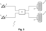
- the invention is here implemented in an electric braking system 1 of a helicopter, with the aim of optimizing the braking torque to reduce the risk of damage to the brake structure, and to maintain the expected level of performance.
- the helicopter consists of two nose wheels and two main wheels.
- the two main wheels are 2 braked wheels.
- the electric braking system 1 comprises two brakes 3 each associated with one of the wheels 2.
- Each brake 3 includes a brake actuator which is an electromechanical actuator, as well as a disc, a caliper, and pads.
- the brake actuator acts on a movable pad to pinch the disc between the two pads.
- Each brake 3 thus produces a braking torque to brake the associated wheel 2.
- Braking can be controlled by brake pedals 4 located in the cockpit of the helicopter.
- Each brake pedal 4 is connected to a deflection sensor 5 which measures a deflection of the associated brake pedal 4.
- the electric braking system 1 further comprises a braking computer 6 which is connected to the depression sensors 5.
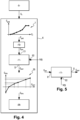
- the associated deflection sensor 5 measures a deflection of the brake pedal 4 and thus produces a braking instruction C f .
- the brake computer 6 acquires the braking instruction C f and generates, from the braking instruction C f , a preliminary braking command C Val for the brake 3 of a wheel 2.
- the preliminary braking command C Val is here a force command.
- the preliminary braking command C prel depends on the braking setpoint C f (and therefore on the deflection measurement) according to a first predetermined curve 7.
- the braking computer 6 performs processing on the preliminary braking command C prel .
- the processing involves the implementation of a plurality of functional blocks, which in particular comprise a slope limiter 10 and a limiter/compensator 11.
- the preliminary braking command C prel is applied to an input of the slope limiter 10.
- the slope limiter 10 makes it possible to limit a peak force occurring, at the start of braking, at the time of application of the braking force by the braking actuator.
- a braking command C om is thus generated at the output of the slope limiter 10.
- the braking command C om is then applied to a first input E1 of the limiter/compensator 11.
- the limiter/compensator 11 includes a second input E2 via which it acquires, in real time, a speed V(t) of the wheel 2.
- This speed V(t) of wheel 2 is here estimated from a measurement of the ground speed of the helicopter.
- the speed of wheel 2 could be obtained differently, for example by directly measuring the speed of wheel 2 using a tachometer mounted on wheel 2.
- the limiter/compensator 11 applies a dynamic correction to the braking command C om .
- the dynamic correction aims to ensure that brake 3 exerts on wheel 2, in response to the braking command C om , a braking torque which is effectively constant whatever the speed of wheel 2.
- Dynamic correction is a function of the brake command and the speed of wheel 2.
- Dynamic correction consists, at the start of braking, when the speed V(t) of wheel 2 is greater than or equal to at a predetermined speed threshold, to produce a corrected braking command C corr greater than the braking command C om .
- the dynamic correction consists of reducing the corrected braking command C corr so that the corrected braking command C corr becomes lower than the braking command C om .
- the corrected brake command C corr is produced on output S of limiter/compensator 11.
- Dynamic correction consists of multiplying the braking command C om by a correction coefficient C c which depends on the braking command C om and the speed V(t) of wheel 2.
- C corr C c C om , V t ⁇ C om , where C corr is the corrected brake command, C om is the brake command, V(t) is the speed of wheel 2 and C c (C om , V(t)) is the correction coefficient which depends on the brake command C om and the speed V(t) of wheel 2.
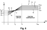
- the correction coefficient C c has a constant value which depends only on the given braking command C om . This constant value is an increasing function of the braking command C om .
- Curve portion 15 corresponds to a maximum braking command, curve portion 16 to a minimum braking command, and curve portions 17 to intermediate braking commands between maximum brake command and minimum brake command.
- the minimum brake command is the brake command below which dynamic correction is not implemented
- the maximum brake command is the brake command above which dynamic correction is not implemented.
- the correction coefficient C c is therefore limited by the minimum correction coefficient C cmin and by the maximum correction coefficient C cmax , which prevents a fault in the corrector from leading to a corrected braking command that is too weak or too strong.
- the correction coefficient C c is an increasing linear function of the speed of wheel 2.
- the slope of the linear function is an increasing function of the braking command C om .
- a value of the correction coefficient C c , at zero speed V(t), is a decreasing function of the braking command C om .
- the value 22 of the correction coefficient C c at zero speed V(t), for the maximum braking command is lower than the values 23 of the correction coefficient C c at zero speed V(t), for the intermediate braking commands, which are themselves lower than the value 24 of the correction coefficient C c at zero speed V(t), for the minimum braking command.
- the predetermined speed threshold S v is for example equal to 11m/s.
- the predetermined speed threshold can be influenced by the value of the brake command and by the predefined wheel speed value.
- the value of the predefined correction coefficient C cp is here equal to 1.
- the corrected braking command C corr is then transformed into a position instruction C ons .
- the position instruction C ons depends on the corrected braking command according to a second predetermined curve 25.
- the position instruction C ons is a linear position value of the pusher of the braking actuator of the brake 3 of the wheel 2.
- the braking computer 6 uses measurements of this linear position, provided by a position sensor located on the braking actuator, and implements a servocontrol 26 to control the linear position of the pusher of the braking actuator.
- the brake computer 6 therefore controls the braking actuator of brake 3 of wheel 2 using the command corrected braking C corr .
- the braking method according to the invention does not implement torque or force control.
- the braking command and the corrected braking command are force commands, but no torque or force measurement is carried out.
- the braking method according to the invention therefore does not require a torque or force sensor.
- the characterization of numerous data files from constant braking force control braking tests made it possible to build a model of the evolution of the torque as a function of the speed, and made it possible to identify the speed threshold S v . This modeling is independent of the initial braking speed.
- the correction coefficient was constructed in order to adapt dynamically to the wheel speed, but also to the braking command, because the level of compensation and/or limiter to be applied is dependent on the request made by the pilot or the avionics.
- the brake computer produces a brake command to a wheel, and that the brake command is corrected according to a dynamic correction which is a function of the brake command and the speed of the wheel.
- the brake command could of course be a global command to several wheels.
- the speed used could be a speed (measured or estimated) representative of the speed of several wheels (for example an average of the speeds of these wheels).
- the architecture of the braking system in which the invention is implemented may of course be different from that presented here.
- the braking system is not necessarily an electric braking system, but could be for example a hydraulic braking system (in which case the correction is for example carried out on the hydraulic pressure and not on a braking command intended to be transformed into a position instruction).
Landscapes
- Engineering & Computer Science (AREA)
- Mechanical Engineering (AREA)
- Aviation & Aerospace Engineering (AREA)
- Transportation (AREA)
- Regulating Braking Force (AREA)
Claims (10)
- Bremsverfahren zum Bremsen von zumindest einem Rad (2) eines Luftfahrzeugs, wobei das Rad mit einer Bremse (3) versehen ist, die zumindest einen Bremsaktor aufweist, wobei das Verfahren die Schritte umfassend, dass:- ein Bremsbefehl (Com) aus einem Bremssollwert (Cf) generiert wird;- eine Radgeschwindigkeit (V(t)) geschätzt und/oder gemessen wird;- eine dynamische Korrektur auf den Bremsbefehl angewendet wird, wobei die dynamische Korrektur von dem Bremsbefehl und von der Radgeschwindigkeit (V(t)) abhängig ist, wobei die dynamische Korrektur den Schritt umfasst, dass ein korrigierter Bremsbefehl (Ccorr) mit höherer Bremskraft als der ursprüngliche Bremsbefehl erzeugt wird, wenn die Radgeschwindigkeit größer oder gleich einem vorbestimmten Geschwindigkeitsschwellenwert (Sv) ist, und anschließend den Schritt umfasst, dass der korrigierte Bremsbefehl bremskraftreduziert wird, wenn die Radgeschwindigkeit unter den vorbestimmten Geschwindigkeitsschwellenwert abfällt, sodass der korrigierte Bremsbefehl eine geringere Bremskraft als der ursprüngliche Bremsbefehl aufweist;- der Bremsaktor der Radbremse mithilfe des korrigierten Bremsbefehls angesteuert wird.
- Bremsverfahren nach Anspruch 1, wobei die dynamische Korrektur darin besteht, dass der Bremsbefehl mit einem Korrekturkoeffizienten (Cc) multipliziert wird, der von dem Bremsbefehl (Com) und von der Radgeschwindigkeit (V(t)) abhängig ist.
- Bremsverfahren nach Anspruch 2, wobei, wenn die Radgeschwindigkeit (V(t)) größer oder gleich dem vorbestimmten Geschwindigkeitsschwellenwert (Sv) ist, der Korrekturkoeffizient (Cc) für einen gegebenen Bremsbefehl einen konstanten Wert aufweist, der ausschließlich von dem Bremsbefehl abhängig ist.
- Bremsverfahren nach Anspruch 3, wobei der konstante Wert eine steigende Funktion des Bremsbefehls (Com) darstellt.
- Bremsverfahren nach Anspruch 2, wobei der Korrekturkoeffizient (Cc) durch einen minimalen Korrekturkoeffizienten (Ccmin) und durch einen maximalen Korrekturkoeffizienten (Ccmax) begrenzt wird.
- Bremsverfahren nach Anspruch 2, wobei, wenn die Radgeschwindigkeit (V(t)) kleiner als der vorbestimmte Geschwindigkeitsschwellenwert (Sv) ist, der Korrekturkoeffizient (Cc) für einen gegebenen Bremsbefehl eine steigende lineare Funktion der Radgeschwindigkeit ((V(t)) darstellt.
- Bremsverfahren nach Anspruch 6, wobei die Neigung der linearen Funktion eine steigende Funktion des Bremsbefehls (Com) ist.
- Bremsverfahren nach Anspruch 6, wobei ein Wert des Korrekturkoeffizienten (Cc) bei Radgeschwindigkeit Null eine abnehmende Funktion des Bremsbefehls (Com) darstellt.
- Bremsverfahren nach Anspruch 6, wobei die lineare Funktion, unabhängig von dem Bremsbefehl (Com), durch ein und denselben Punkt (P) verläuft, der durch einen vordefinierten Radgeschwindigkeitswert (Vp) und durch einen vordefinierten Koeffizientenwert definiert ist.
- Bremsverfahren nach Anspruch 9, wobei der vordefinierte Koeffizientenwert gleich 1 ist.
Applications Claiming Priority (2)
| Application Number | Priority Date | Filing Date | Title |
|---|---|---|---|
| FR1912531A FR3102963B1 (fr) | 2019-11-07 | 2019-11-07 | Procédé de freinage d’aéronef, comprenant une correction dynamique de la commande de freinage |
| PCT/EP2020/081162 WO2021089714A1 (fr) | 2019-11-07 | 2020-11-05 | Procede de freinage d'aeronef, comprenant une correction dynamique de la commande de freinage |
Publications (2)
| Publication Number | Publication Date |
|---|---|
| EP4054906A1 EP4054906A1 (de) | 2022-09-14 |
| EP4054906B1 true EP4054906B1 (de) | 2025-01-01 |
Family
ID=69700041
Family Applications (1)
| Application Number | Title | Priority Date | Filing Date |
|---|---|---|---|
| EP20801267.4A Active EP4054906B1 (de) | 2019-11-07 | 2020-11-05 | Flugzeugbremsverfahren mit dynamischer korrektur des bremsbefehls |
Country Status (5)
| Country | Link |
|---|---|
| US (1) | US12037107B2 (de) |
| EP (1) | EP4054906B1 (de) |
| CN (1) | CN114650937B (de) |
| FR (1) | FR3102963B1 (de) |
| WO (1) | WO2021089714A1 (de) |
Families Citing this family (1)
| Publication number | Priority date | Publication date | Assignee | Title |
|---|---|---|---|---|
| US11702193B1 (en) * | 2022-04-28 | 2023-07-18 | Beta Air, Llc | Systems and methods for an electric vertical takeoff and landing aircraft braking system |
Family Cites Families (9)
| Publication number | Priority date | Publication date | Assignee | Title |
|---|---|---|---|---|
| US5968106A (en) * | 1997-08-05 | 1999-10-19 | The Boeing Company | Aircraft stop-to-position autobrake control system |
| US6882920B2 (en) * | 2003-04-29 | 2005-04-19 | Goodrich Corporation | Brake control system |
| US8083295B2 (en) * | 2008-07-16 | 2011-12-27 | Hydro-Aire, Inc. | Method of maintaining optimal braking and skid protection for a two-wheeled vehicle having a speed sensor failure on a single wheel |
| FR3007096B1 (fr) | 2013-06-17 | 2016-09-23 | Messier Bugatti Dowty | Frein pour roue d'aeronef, en particulier pour un helicoptere. |
| FR3008368B1 (fr) * | 2013-07-10 | 2016-09-23 | Messier Bugatti Dowty | Procede de gestion du freinage d'un aeronef |
| GB201315012D0 (en) * | 2013-08-22 | 2013-10-02 | Airbus Uk Ltd | Aircraft autonomous pushback |
| US9950699B2 (en) * | 2013-09-26 | 2018-04-24 | The Boeing Company | Brake load alleviation functions |
| CN104401305B (zh) * | 2014-11-18 | 2017-01-25 | 西安航空制动科技有限公司 | 一种飞机刹车控制方法 |
| GB2540183A (en) * | 2015-07-08 | 2017-01-11 | Airbus Operations Ltd | Braking control system for an aircraft |
-
2019
- 2019-11-07 FR FR1912531A patent/FR3102963B1/fr active Active
-
2020
- 2020-11-05 US US17/775,112 patent/US12037107B2/en active Active
- 2020-11-05 WO PCT/EP2020/081162 patent/WO2021089714A1/fr not_active Ceased
- 2020-11-05 CN CN202080077906.7A patent/CN114650937B/zh active Active
- 2020-11-05 EP EP20801267.4A patent/EP4054906B1/de active Active
Also Published As
| Publication number | Publication date |
|---|---|
| US12037107B2 (en) | 2024-07-16 |
| FR3102963A1 (fr) | 2021-05-14 |
| FR3102963B1 (fr) | 2021-11-12 |
| US20220388637A1 (en) | 2022-12-08 |
| EP4054906A1 (de) | 2022-09-14 |
| CN114650937B (zh) | 2025-04-08 |
| WO2021089714A1 (fr) | 2021-05-14 |
| CN114650937A (zh) | 2022-06-21 |
Similar Documents
| Publication | Publication Date | Title |
|---|---|---|
| EP1935732B1 (de) | Adaptatives Bremssteurungsverfahren für Fahrzeuge | |
| EP2917537B1 (de) | Verfahren zur überwachung eines schubkraftfehlers eines mantelstrom-triebwerks eines flugzeugs | |
| US10434996B2 (en) | Method for estimating coefficient of friction of a hydraulic brake system | |
| EP3718883A1 (de) | Steuerverfahren einer bremsvorrichtung | |
| EP2096011B1 (de) | Verfahren zur Steuerung einer Kraftfahrzeugbremse mit Dehnungskompensation | |
| EP4054906B1 (de) | Flugzeugbremsverfahren mit dynamischer korrektur des bremsbefehls | |
| FR2684345A1 (fr) | Procede pour determiner une valeur optimisee du rapport entre les pressions de freinage d'un vehicule tracteur et d'une remorque ou semi-remorque. | |
| EP2902285A1 (de) | Überwachungsverfahren von mindestens zwei elektromechanischen Bremsstellgliedern | |
| EP2017149B1 (de) | Verfahren zur Steuerung einer Kraftfahrzeugbremse mit Drehmomentkorrektur | |
| EP1586968B1 (de) | System zur längsgerichteten Führung eines am Boden rollenden Flugzeuges | |
| EP3010746B1 (de) | System und verfahren zur überwachung des durch den motor eines elektro- oder hybridmotorfahrzeugs erzeugten drehmoments | |
| CN111412274B (zh) | Cvt控制器钢带防打滑控制方法 | |
| EP3718841B1 (de) | Bremssystem eines luftfahrzeugrads, das gemäss normal-modus oder rto-modus eingestellt werden kann | |
| EP3268255B1 (de) | Verfahren zur verteilung des drehmoments zwischen den radsätzen eines kraftfahrzeugs | |
| FR3008368A1 (fr) | Procede de gestion du freinage d'un aeronef | |
| EP2297476B1 (de) | Modul zur drehmomentsteuerung einer reibkupplungsvorrichtung eines kraftfahrzeugantriebsstrangs mit zustandsbeobachter | |
| EP1587723B1 (de) | Bremssystem und berechnungsverfahren eines sollverzögerungswerts für bremsstellglieder eines fahrzeugs | |
| FR2916274A1 (fr) | Dispositif et procede d'estimation des jeux dans une chaine de transmission d'un vehicule. | |
| EP4135994B1 (de) | Vorrichtung und verfahren zum bremsen eines kraftfahrzeugs mit einer elektrischen maschine | |
| FR3013275A1 (fr) | Procede d'elaboration d'un couple de consigne d'un moteur electrique de vehicule automobile et groupe motopropulseur associe | |
| FR2920501A1 (fr) | Procede et systeme de pilotage d'un organe de couplage d'une chaine de traction d'un vehicule automobile | |
| EP1844962B1 (de) | Verfahren zur Steuerung der Federung eines Kraftfahrzeugs und System, in das dieses Steuerungsverfahren integriert ist | |
| WO2021018988A1 (fr) | Dispositif de freinage d'une roue | |
| FR3166675A1 (fr) | Méthode d’estimation de température d’un disque de frein embarqué dans un véhicule | |
| FR3019109A1 (fr) | Pedale d'accelerateur et vehicule hybride comportant une telle pedale |
Legal Events
| Date | Code | Title | Description |
|---|---|---|---|
| STAA | Information on the status of an ep patent application or granted ep patent |
Free format text: STATUS: UNKNOWN |
|
| STAA | Information on the status of an ep patent application or granted ep patent |
Free format text: STATUS: THE INTERNATIONAL PUBLICATION HAS BEEN MADE |
|
| PUAI | Public reference made under article 153(3) epc to a published international application that has entered the european phase |
Free format text: ORIGINAL CODE: 0009012 |
|
| STAA | Information on the status of an ep patent application or granted ep patent |
Free format text: STATUS: REQUEST FOR EXAMINATION WAS MADE |
|
| 17P | Request for examination filed |
Effective date: 20220603 |
|
| AK | Designated contracting states |
Kind code of ref document: A1 Designated state(s): AL AT BE BG CH CY CZ DE DK EE ES FI FR GB GR HR HU IE IS IT LI LT LU LV MC MK MT NL NO PL PT RO RS SE SI SK SM TR |
|
| DAV | Request for validation of the european patent (deleted) | ||
| DAX | Request for extension of the european patent (deleted) | ||
| GRAP | Despatch of communication of intention to grant a patent |
Free format text: ORIGINAL CODE: EPIDOSNIGR1 |
|
| STAA | Information on the status of an ep patent application or granted ep patent |
Free format text: STATUS: GRANT OF PATENT IS INTENDED |
|
| INTG | Intention to grant announced |
Effective date: 20240716 |
|
| GRAS | Grant fee paid |
Free format text: ORIGINAL CODE: EPIDOSNIGR3 |
|
| GRAA | (expected) grant |
Free format text: ORIGINAL CODE: 0009210 |
|
| STAA | Information on the status of an ep patent application or granted ep patent |
Free format text: STATUS: THE PATENT HAS BEEN GRANTED |
|
| AK | Designated contracting states |
Kind code of ref document: B1 Designated state(s): AL AT BE BG CH CY CZ DE DK EE ES FI FR GB GR HR HU IE IS IT LI LT LU LV MC MK MT NL NO PL PT RO RS SE SI SK SM TR |
|
| REG | Reference to a national code |
Ref country code: GB Ref legal event code: FG4D Free format text: NOT ENGLISH |
|
| REG | Reference to a national code |
Ref country code: DE Ref legal event code: R096 Ref document number: 602020044139 Country of ref document: DE |
|
| REG | Reference to a national code |
Ref country code: CH Ref legal event code: EP |
|
| REG | Reference to a national code |
Ref country code: IE Ref legal event code: FG4D Free format text: LANGUAGE OF EP DOCUMENT: FRENCH |
|
| REG | Reference to a national code |
Ref country code: LT Ref legal event code: MG9D |
|
| REG | Reference to a national code |
Ref country code: NL Ref legal event code: MP Effective date: 20250101 |
|
| REG | Reference to a national code |
Ref country code: AT Ref legal event code: MK05 Ref document number: 1755946 Country of ref document: AT Kind code of ref document: T Effective date: 20250101 |
|
| PG25 | Lapsed in a contracting state [announced via postgrant information from national office to epo] |
Ref country code: NL Free format text: LAPSE BECAUSE OF FAILURE TO SUBMIT A TRANSLATION OF THE DESCRIPTION OR TO PAY THE FEE WITHIN THE PRESCRIBED TIME-LIMIT Effective date: 20250101 |
|
| PG25 | Lapsed in a contracting state [announced via postgrant information from national office to epo] |
Ref country code: FI Free format text: LAPSE BECAUSE OF FAILURE TO SUBMIT A TRANSLATION OF THE DESCRIPTION OR TO PAY THE FEE WITHIN THE PRESCRIBED TIME-LIMIT Effective date: 20250101 |
|
| PG25 | Lapsed in a contracting state [announced via postgrant information from national office to epo] |
Ref country code: PL Free format text: LAPSE BECAUSE OF FAILURE TO SUBMIT A TRANSLATION OF THE DESCRIPTION OR TO PAY THE FEE WITHIN THE PRESCRIBED TIME-LIMIT Effective date: 20250101 |
|
| PG25 | Lapsed in a contracting state [announced via postgrant information from national office to epo] |
Ref country code: ES Free format text: LAPSE BECAUSE OF FAILURE TO SUBMIT A TRANSLATION OF THE DESCRIPTION OR TO PAY THE FEE WITHIN THE PRESCRIBED TIME-LIMIT Effective date: 20250101 |
|
| PG25 | Lapsed in a contracting state [announced via postgrant information from national office to epo] |
Ref country code: NO Free format text: LAPSE BECAUSE OF FAILURE TO SUBMIT A TRANSLATION OF THE DESCRIPTION OR TO PAY THE FEE WITHIN THE PRESCRIBED TIME-LIMIT Effective date: 20250401 Ref country code: IS Free format text: LAPSE BECAUSE OF FAILURE TO SUBMIT A TRANSLATION OF THE DESCRIPTION OR TO PAY THE FEE WITHIN THE PRESCRIBED TIME-LIMIT Effective date: 20250501 |
|
| PG25 | Lapsed in a contracting state [announced via postgrant information from national office to epo] |
Ref country code: HR Free format text: LAPSE BECAUSE OF FAILURE TO SUBMIT A TRANSLATION OF THE DESCRIPTION OR TO PAY THE FEE WITHIN THE PRESCRIBED TIME-LIMIT Effective date: 20250101 |
|
| PG25 | Lapsed in a contracting state [announced via postgrant information from national office to epo] |
Ref country code: LV Free format text: LAPSE BECAUSE OF FAILURE TO SUBMIT A TRANSLATION OF THE DESCRIPTION OR TO PAY THE FEE WITHIN THE PRESCRIBED TIME-LIMIT Effective date: 20250101 Ref country code: PT Free format text: LAPSE BECAUSE OF FAILURE TO SUBMIT A TRANSLATION OF THE DESCRIPTION OR TO PAY THE FEE WITHIN THE PRESCRIBED TIME-LIMIT Effective date: 20250502 |
|
| PG25 | Lapsed in a contracting state [announced via postgrant information from national office to epo] |
Ref country code: GR Free format text: LAPSE BECAUSE OF FAILURE TO SUBMIT A TRANSLATION OF THE DESCRIPTION OR TO PAY THE FEE WITHIN THE PRESCRIBED TIME-LIMIT Effective date: 20250402 Ref country code: BG Free format text: LAPSE BECAUSE OF FAILURE TO SUBMIT A TRANSLATION OF THE DESCRIPTION OR TO PAY THE FEE WITHIN THE PRESCRIBED TIME-LIMIT Effective date: 20250101 |
|
| PG25 | Lapsed in a contracting state [announced via postgrant information from national office to epo] |
Ref country code: AT Free format text: LAPSE BECAUSE OF FAILURE TO SUBMIT A TRANSLATION OF THE DESCRIPTION OR TO PAY THE FEE WITHIN THE PRESCRIBED TIME-LIMIT Effective date: 20250101 |
|
| PG25 | Lapsed in a contracting state [announced via postgrant information from national office to epo] |
Ref country code: CZ Free format text: LAPSE BECAUSE OF FAILURE TO SUBMIT A TRANSLATION OF THE DESCRIPTION OR TO PAY THE FEE WITHIN THE PRESCRIBED TIME-LIMIT Effective date: 20250101 |
|
| PG25 | Lapsed in a contracting state [announced via postgrant information from national office to epo] |
Ref country code: SE Free format text: LAPSE BECAUSE OF FAILURE TO SUBMIT A TRANSLATION OF THE DESCRIPTION OR TO PAY THE FEE WITHIN THE PRESCRIBED TIME-LIMIT Effective date: 20250101 |
|
| REG | Reference to a national code |
Ref country code: DE Ref legal event code: R097 Ref document number: 602020044139 Country of ref document: DE |
|
| PG25 | Lapsed in a contracting state [announced via postgrant information from national office to epo] |
Ref country code: SM Free format text: LAPSE BECAUSE OF FAILURE TO SUBMIT A TRANSLATION OF THE DESCRIPTION OR TO PAY THE FEE WITHIN THE PRESCRIBED TIME-LIMIT Effective date: 20250101 |
|
| PG25 | Lapsed in a contracting state [announced via postgrant information from national office to epo] |
Ref country code: DK Free format text: LAPSE BECAUSE OF FAILURE TO SUBMIT A TRANSLATION OF THE DESCRIPTION OR TO PAY THE FEE WITHIN THE PRESCRIBED TIME-LIMIT Effective date: 20250101 |
|
| PG25 | Lapsed in a contracting state [announced via postgrant information from national office to epo] |
Ref country code: IT Free format text: LAPSE BECAUSE OF FAILURE TO SUBMIT A TRANSLATION OF THE DESCRIPTION OR TO PAY THE FEE WITHIN THE PRESCRIBED TIME-LIMIT Effective date: 20250101 |
|
| PG25 | Lapsed in a contracting state [announced via postgrant information from national office to epo] |
Ref country code: EE Free format text: LAPSE BECAUSE OF FAILURE TO SUBMIT A TRANSLATION OF THE DESCRIPTION OR TO PAY THE FEE WITHIN THE PRESCRIBED TIME-LIMIT Effective date: 20250101 |
|
| PG25 | Lapsed in a contracting state [announced via postgrant information from national office to epo] |
Ref country code: RO Free format text: LAPSE BECAUSE OF FAILURE TO SUBMIT A TRANSLATION OF THE DESCRIPTION OR TO PAY THE FEE WITHIN THE PRESCRIBED TIME-LIMIT Effective date: 20250101 |
|
| PG25 | Lapsed in a contracting state [announced via postgrant information from national office to epo] |
Ref country code: SK Free format text: LAPSE BECAUSE OF FAILURE TO SUBMIT A TRANSLATION OF THE DESCRIPTION OR TO PAY THE FEE WITHIN THE PRESCRIBED TIME-LIMIT Effective date: 20250101 |
|
| PLBE | No opposition filed within time limit |
Free format text: ORIGINAL CODE: 0009261 |
|
| STAA | Information on the status of an ep patent application or granted ep patent |
Free format text: STATUS: NO OPPOSITION FILED WITHIN TIME LIMIT |
|
| 26N | No opposition filed |
Effective date: 20251002 |
|
| PGFP | Annual fee paid to national office [announced via postgrant information from national office to epo] |
Ref country code: DE Payment date: 20251118 Year of fee payment: 6 |
|
| PGFP | Annual fee paid to national office [announced via postgrant information from national office to epo] |
Ref country code: GB Payment date: 20251125 Year of fee payment: 6 |
|
| PGFP | Annual fee paid to national office [announced via postgrant information from national office to epo] |
Ref country code: FR Payment date: 20251125 Year of fee payment: 6 |