EP3718882B1 - Method and system for operating an aircraft powerplant - Google Patents
Method and system for operating an aircraft powerplant Download PDFInfo
- Publication number
- EP3718882B1 EP3718882B1 EP20167610.3A EP20167610A EP3718882B1 EP 3718882 B1 EP3718882 B1 EP 3718882B1 EP 20167610 A EP20167610 A EP 20167610A EP 3718882 B1 EP3718882 B1 EP 3718882B1
- Authority
- EP
- European Patent Office
- Prior art keywords
- reverse thrust
- propeller
- aircraft
- blade angle
- power lever
- Prior art date
- Legal status (The legal status is an assumption and is not a legal conclusion. Google has not performed a legal analysis and makes no representation as to the accuracy of the status listed.)
- Active
Links
- 238000000034 method Methods 0.000 title claims description 31
- 238000012545 processing Methods 0.000 claims description 14
- 230000004044 response Effects 0.000 claims description 8
- 230000003247 decreasing effect Effects 0.000 claims description 6
- 239000000446 fuel Substances 0.000 description 16
- 230000007704 transition Effects 0.000 description 5
- 238000010586 diagram Methods 0.000 description 4
- 230000009977 dual effect Effects 0.000 description 4
- 230000006870 function Effects 0.000 description 4
- 239000007789 gas Substances 0.000 description 4
- 239000003570 air Substances 0.000 description 2
- 238000013459 approach Methods 0.000 description 2
- 239000000567 combustion gas Substances 0.000 description 2
- 238000004891 communication Methods 0.000 description 2
- 238000004590 computer program Methods 0.000 description 2
- 238000005259 measurement Methods 0.000 description 2
- 230000007246 mechanism Effects 0.000 description 2
- 238000012986 modification Methods 0.000 description 2
- 230000004048 modification Effects 0.000 description 2
- 230000003287 optical effect Effects 0.000 description 2
- 230000001960 triggered effect Effects 0.000 description 2
- 230000009471 action Effects 0.000 description 1
- 239000012080 ambient air Substances 0.000 description 1
- 230000008859 change Effects 0.000 description 1
- 239000010720 hydraulic oil Substances 0.000 description 1
- 230000006872 improvement Effects 0.000 description 1
- 239000003921 oil Substances 0.000 description 1
- 230000001141 propulsive effect Effects 0.000 description 1
- 230000009467 reduction Effects 0.000 description 1
- 238000012552 review Methods 0.000 description 1
- 239000004065 semiconductor Substances 0.000 description 1
- 238000009987 spinning Methods 0.000 description 1
Images


Classifications
-
- B—PERFORMING OPERATIONS; TRANSPORTING
- B64—AIRCRAFT; AVIATION; COSMONAUTICS
- B64C—AEROPLANES; HELICOPTERS
- B64C11/00—Propellers, e.g. of ducted type; Features common to propellers and rotors for rotorcraft
- B64C11/30—Blade pitch-changing mechanisms
- B64C11/44—Blade pitch-changing mechanisms electric
-
- B—PERFORMING OPERATIONS; TRANSPORTING
- B64—AIRCRAFT; AVIATION; COSMONAUTICS
- B64C—AEROPLANES; HELICOPTERS
- B64C11/00—Propellers, e.g. of ducted type; Features common to propellers and rotors for rotorcraft
- B64C11/30—Blade pitch-changing mechanisms
- B64C11/305—Blade pitch-changing mechanisms characterised by being influenced by other control systems, e.g. fuel supply
-
- B—PERFORMING OPERATIONS; TRANSPORTING
- B64—AIRCRAFT; AVIATION; COSMONAUTICS
- B64D—EQUIPMENT FOR FITTING IN OR TO AIRCRAFT; FLIGHT SUITS; PARACHUTES; ARRANGEMENTS OR MOUNTING OF POWER PLANTS OR PROPULSION TRANSMISSIONS IN AIRCRAFT
- B64D31/00—Power plant control; Arrangement thereof
-
- F—MECHANICAL ENGINEERING; LIGHTING; HEATING; WEAPONS; BLASTING
- F02—COMBUSTION ENGINES; HOT-GAS OR COMBUSTION-PRODUCT ENGINE PLANTS
- F02C—GAS-TURBINE PLANTS; AIR INTAKES FOR JET-PROPULSION PLANTS; CONTROLLING FUEL SUPPLY IN AIR-BREATHING JET-PROPULSION PLANTS
- F02C9/00—Controlling gas-turbine plants; Controlling fuel supply in air- breathing jet-propulsion plants
- F02C9/48—Control of fuel supply conjointly with another control of the plant
- F02C9/56—Control of fuel supply conjointly with another control of the plant with power transmission control
- F02C9/58—Control of fuel supply conjointly with another control of the plant with power transmission control with control of a variable-pitch propeller
-
- F—MECHANICAL ENGINEERING; LIGHTING; HEATING; WEAPONS; BLASTING
- F02—COMBUSTION ENGINES; HOT-GAS OR COMBUSTION-PRODUCT ENGINE PLANTS
- F02D—CONTROLLING COMBUSTION ENGINES
- F02D29/00—Controlling engines, such controlling being peculiar to the devices driven thereby, the devices being other than parts or accessories essential to engine operation, e.g. controlling of engines by signals external thereto
- F02D29/02—Controlling engines, such controlling being peculiar to the devices driven thereby, the devices being other than parts or accessories essential to engine operation, e.g. controlling of engines by signals external thereto peculiar to engines driving vehicles; peculiar to engines driving variable pitch propellers
-
- B—PERFORMING OPERATIONS; TRANSPORTING
- B64—AIRCRAFT; AVIATION; COSMONAUTICS
- B64D—EQUIPMENT FOR FITTING IN OR TO AIRCRAFT; FLIGHT SUITS; PARACHUTES; ARRANGEMENTS OR MOUNTING OF POWER PLANTS OR PROPULSION TRANSMISSIONS IN AIRCRAFT
- B64D27/00—Arrangement or mounting of power plant in aircraft; Aircraft characterised thereby
- B64D27/02—Aircraft characterised by the type or position of power plant
- B64D27/10—Aircraft characterised by the type or position of power plant of gas-turbine type
Definitions
- the present disclosure relates generally to aircraft powerplants, and more particularly to controlling powerplant operation.
- a control system may adjust the blade angle of the propeller blades to cause a transition from forward to reverse thrust, for example during the landing phase.
- the transition from forward to reverse thrust requires that the propeller blades transition through a zone of operation known as "disking" or blade angle of minimum rotational drag, where the engine typically operates at low power.
- a pilot uses feedback of the position of the propeller blade angle to determine when to apply an increase in engine power at landing. However, if an increase in engine power is applied too soon when the propeller blades are transitioning from forward to reverse pitch during landing, positive thrust may occur rather than reverse thrust.
- EP 3 351 772 A1 discloses a prior art control system and method for managing a reverse-mode operation in a gas turbine engine.
- EP 3 447 269 A1 discloses a prior art method and system for limiting power of a gas turbine engine.
- a method for operating an aircraft powerplant comprising an engine coupled to a variable-pitch propeller capable of generating forward and reverse thrust as recited in claim 1.
- the selected idle region is a range between a ground idle position and a flight idle position of the power lever, inclusive of the ground idle position and the flight idle position.
- the selected idle region is a flight idle position of the power lever.
- the method further comprises determining that the reverse thrust conditions have been met when a forward airspeed of the aircraft is below a minimum forward speed threshold.
- triggering reverse thrust comprises decreasing the blade angle of the propeller at a predetermined rate towards a full reverse blade angle and increasing engine power at a predetermined rate towards a full reverse power of the engine.
- triggering reverse thrust of the propeller comprises applying reverse thrust for a period of time determined based on a weight of the aircraft.
- the method further comprises ending the reverse thrust when a forward airspeed of the aircraft is below a ground minimum speed threshold, and/or when the power lever is moved out of the selected idle region, and/or in response to receiving a request to disable the mode for automated reverse thrust.
- a system for operating an aircraft powerplant comprising an engine coupled to a variable-pitch propeller capable of generating forward and reverse thrust as recited in claim 8.
- the selected idle region is a range between a ground idle position and a flight idle position of the power lever, inclusive of the ground idle position and the flight idle position.
- the selected idle region is a flight idle position of the power lever.
- the program instructions are further executable by the at least one processing unit for determining that the reverse thrust conditions have been met when a forward airspeed of the aircraft is below a minimum forward speed threshold.
- triggering reverse thrust comprises decreasing the blade angle of the propeller at a predetermined rate towards a full reverse blade angle and increasing engine power at a predetermined rate towards a full reverse power of the engine.
- triggering reverse thrust of the propeller comprises applying reverse thrust for a period of time determined based on a weight of the aircraft.
- the program instructions are further executable by the at least one processing unit for ending the reverse thrust when a forward airspeed of the aircraft is below a ground minimum speed threshold, and/or when the power lever is moved out of the selected idle region, and/or in response to receiving a request to disable the mode for automated reverse thrust.
- Figure 1 illustrates an aircraft powerplant 100 for an aircraft of a type preferably provided for use in subsonic flight, generally comprising an engine 110 and a propeller 120.
- the powerplant 100 generally comprises in serial flow communication the propeller 120 attached to a shaft 108 and through which ambient air is propelled, a compressor section 114 for pressurizing the air, a combustor 116 in which the compressed air is mixed with fuel and ignited for generating an annular stream of hot combustion gases, and a turbine section 106 for extracting energy from the combustion gases driving the rotation of the propeller through shaft 108.
- the propeller 120 converts rotary motion from the shaft 108 of the engine 110 to provide propulsive force for the aircraft, also known as thrust.
- the propeller 120 is variable-pitch propeller capable of generating forward and reverse thrust.
- the propeller 120 comprises two or more propeller blades 122.
- a blade angle of the propeller blades 122 may be adjusted.
- the blade angle may be referred to as a beta angle, an angle of attack or a blade pitch.
- the powerplant 100 may be implemented to comprise a single or multi-spool gas turbine engine, where the turbine section 106 is typically connected to the propeller 120 through a reduction gearbox (RGB).
- RGB reduction gearbox
- a control system 210 receives a power lever or throttle position from a power lever 212 of the aircraft under control by a pilot or other operator of the aircraft.
- the power lever position is indicative of the type of thrust demanded by the power lever 212.
- power lever positions can be selected, including those for (1) maximum forward thrust (MAX FWD), which is typically used during takeoff; (2) flight idle (FLT IDLE), which may be used in flight during approach or during taxiing on the ground; (3) ground idle (GND IDLE), at which the propeller 120 is spinning, but providing very low thrust; (4) maximum reverse thrust (MAX REV), which is typically used at landing in order to slow the aircraft. Intermediate positions between the abovementioned positions can also be selected.
- the power lever positions may vary depending on practical implementations of the power lever 212. In some embodiments, the power lever 212 does not comprise a region for requesting reverse thrust.
- the control system 210 receives additional inputs pertaining to the operation of the propeller 120, engine 110 and/or the aircraft.
- the control system 210 receives a blade angle of the propeller 120.
- the control system 210 receives an aircraft status indicative of whether the aircraft is on-ground or in-flight.
- the aircraft status may be a weight-on-wheels condition received from an aircraft computer.
- the control system 210 determines the aircraft status based on one or more of the additional inputs.
- the control system 210 receives a forward airspeed of the aircraft.
- the additional inputs may vary depending on practical implementations.
- the control system 210 is configured to control the engine 110 and the propeller 120 based on the received inputs.
- the control system 210 controls the engine 110 by outputting a fuel flow request to an engine actuator 216 for adjusting engine fuel flow and controls the propeller 120 by outputting a propeller blade angle request to a propeller actuator 214 for adjusting the blade angle of the propeller 120.
- the engine actuator 216 and/or propeller actuator 214 may each be implemented as a torque motor, a stepper motor, or any other suitable actuator.
- the engine actuator 216 may be implemented as one or more valves that regulate fuel flow from a fuel source to the engine 110.
- the control system 210 determines the fuel flow request for adjusting engine fuel flow and the propeller blade angle request for adjusting the blade angle of the propeller 120 based on the received inputs.
- the propeller actuator 214 may control hydraulic oil pressure to adjust the blade angle based on the propeller blade angle request.
- the propeller blade angle request is an oil flow request to set the propeller blade angle.
- the engine actuator 216 can adjust the fuel flow to the engine 110 based on the fuel flow request. While the engine actuator 216 and the propeller actuator 214 are illustrated as being part of the engine 110 and the propeller 120, respectively, it should be understood that this is for illustrative purposes only and that the engine actuator 216 and/or the propeller actuator 214 may, in some embodiments, be separate from the powerplant 100. While the controller 210 is illustrated as separate from the powerplant 100, it should be understood that this is for illustrative purposes only and that the controller 210 may, in some embodiments, be integrated with the powerplant 100.
- the control system 210 is configured to receive a request to enable a mode for automated reverse thrust of the propeller 120 (referred to herein as the "automated reverse thrust mode").
- the automated reverse thrust mode is a mode of the control system 210 for operating the engine 110 and the propeller 120 in a manner to cause the propeller to provide reverse thrust at landing without a direct request for reverse thrust from the power lever 212.
- the request to enable the automated reverse thrust mode may be received in various manners, for example from an aircraft computer connected to a cockpit interface (e.g., an illuminated push-button) used to select and deselect the automated reverse thrust mode.
- a cockpit interface e.g., an illuminated push-button
- one or more of the power lever positions may correspond to a request for the automated reverse thrust mode.
- the control system 210 is configured to trigger reverse thrust of the propeller 120 when the automated reverse thrust mode is enabled and when certain reverse thrust conditions have been met.
- control system 210 is configured to determine that the reverse thrust conditions are met when the aircraft is on-ground, a blade angle of the propeller 120 is below a blade angle threshold and a position of the power lever 212 is at a selected idle region of the power lever 212. In some embodiments, the reverse thrust conditions are met when the aforementioned conditions are met and a forward airspeed of the aircraft is below a minimum forward speed threshold .
- the selected idle region may be a range of the power lever 212.
- the selected idle region can be a range between the ground idle position and the flight idle position of the power lever 212.
- the range between the ground idle position and the flight idle position of the power lever 212 is inclusive of the ground idle position and/or the flight idle position.
- the selected idle region may be a specific position of the power lever 212.
- the specific position may be the flight idle position of the power lever 212. It should be appreciated that the selected idle region does not correspond to a region of the power lever 212 normally used for requesting reverse thrust.
- Triggering reverse thrust corresponds to any response mechanism(s) and/or action(s) to cause the propeller to provide reverse thrust.
- Triggering reverse thrust comprises the control system 210 adjusting the blade angle of the propeller 120 and adjusting the engine power by adjusting engine fuel flow to cause the propeller 120 to provide reverse thrust.
- the control system 210 triggers reverse thrust by decreasing the blade angle of the propeller 120 at a predetermined rate towards a full reverse blade angle and increasing engine power at a predetermined rate towards a full reverse power of the engine 110.
- the control system 210 reduces engine power and adjusts the blade angle of the propeller 120 to stop the propeller 120 from providing reverse thrust.
- reverse thrust occurs automatically without any direct request from the pilot (i.e., without the pilot moving the power lever 212 into a reverse thrust regime of the power lever 212). It should further be appreciated that by not having the pilot move the power lever 212 into a reverse thrust regime of the power lever 212 to request reverse thrust, this prevents the propeller 120 from inadvertently providing positive thrust.
- a propeller controller 252 controls the propeller 120 and an engine controller 254 controls the engine 110.
- the propeller controller 252 determines and outputs the propeller blade angle request and the engine controller 254 determines and outputs the fuel flow request.
- the propeller controller 252 receives the inputs (e.g., the power lever position, blade angle, aircraft status, forward airspeed and/or any other suitable inputs) and is in electronic communication with the engine controller for providing one or more of the received inputs to the engine controller 254.
- the engine controller 254 additionally or alternatively receives the inputs (e.g., the power lever position, blade angle, aircraft status, forward airspeed and/or any other suitable inputs). In some embodiments, the engine controller 254 provides one or more of the received inputs to the propeller controller 252. In some embodiments, the propeller controller 252 may determine the blade angle of the propeller 120 and provide the blade angle to the engine controller 254. In alternative embodiments, the functionalities of the propeller controller 252 and the engine controller 254 may be implemented in a single controller.
- the inputs e.g., the power lever position, blade angle, aircraft status, forward airspeed and/or any other suitable inputs. In some embodiments, the engine controller 254 provides one or more of the received inputs to the propeller controller 252. In some embodiments, the propeller controller 252 may determine the blade angle of the propeller 120 and provide the blade angle to the engine controller 254. In alternative embodiments, the functionalities of the propeller controller 252 and the engine controller 254 may be implemented in a single controller.
- the pilot When the aircraft is in-flight (e.g., during descent of the aircraft), the pilot enables the automated reverse thrust mode by pushing an automated reverse thrust mode push-button of the cockpit interface from OFF to ON. As the aircraft approaches the runway, the pilot sets the power lever 212 at the flight idle position. When the aircraft touches down on the ground, the pilot maintains the power lever 212 at the flight idle position.
- the engine controller 254 automatically adjusts the engine power and the propeller controller 252 automatically adjusts the blade angle of the propeller 120 such that there is a transition to maximum reverse power and maximum reverse blade angle, resulting in maximum reverse thrust.
- the engine controller 254 reduces the engine power and the propeller controller 252 adjusts the blade angle of the propeller 120 to correspond to the engine power and blade angle for the ground idle position in order for the propeller 120 to stop providing reverse thrust.
- each of the propeller controller 252 and the engine controller 254 comprise two or more channels, such as channels A and B.
- the channels A, B are redundant channels and one of the channels (e.g., channel A) is selected as being active, while the other channel remains in standby (e.g., channel B).
- a channel is active, that channel is configured to generate and output the fuel flow request and/or the propeller blade angle request, and when a channel is in standby, that channel does not generate and output the fuel flow request or the propeller blade angle request.
- the channel When a channel is in standby, the channel is functional and able to take over control when needed. If it is determined that the presently active channel or one of the actuators 214, 216 is faulty or inoperative, the presently active channel may be inactivated and the channel in standby is activated. Similarly, if, during operation, an input to a presently active channel is erroneous or inexistent, the presently active channel may be inactivated and one of the channels in standby is activated.
- each channel A, B of the propeller controller 252 receives the power lever position from at least one sensor 224.
- Each channel A, B of the propeller controller 252 receives the power lever position from at least one sensor 222 (or aircraft computer).
- Each channel A, B of the propeller controller 252 receives the blade angle of the propeller 120 from at least one sensor 224 (or aircraft computer).
- Each channel A, B of the propeller controller 252 receives the aircraft status from at least one sensor 226 (or aircraft computer).
- Each channel A, B of the propeller controller 252 also receives the forward airspeed from at least one sensor 228 (or aircraft computer).
- One or more of the sensors 222, 224, 226, 228 may be implemented with a dual sensing devices, where one sensing element provides a first measurement to channel A and the other sensing element provides a second measurement to channel B.
- the propeller actuator 214 e.g., a dual input pitch change mechanism actuator
- the engine controller 254 receives the blade angle, the power lever position, aircraft status and forward airspeed from the propeller controller 254.
- the engine controller 254 receives the blade angle, the power lever position, aircraft status and forward airspeed from sensors, such as the sensors 222, 224, 226, 228, from an aircraft computer, or a combination thereof.
- the engine actuator 216 (e.g., a dual input fuel metering toque motor) modulates fuel flow to engine 110 based on the fuel flow request from the active channel of the engine controller 254.
- the functionalities of the propeller controller 252 and the engine controller 254 of Figure 2C may be implemented in a single dual-channel controller.
- a flowchart of a method 300 for operating a powerplant such as the powerplant 100.
- the method 300 may be performed by the control system 210, the engine controller 254, propeller controller 252 or a combination thereof.
- a request to enable the mode for automated reverse thrust is received.
- the method 300 comprises determining that reverse thrust conditions have been met.
- the reverse thrust conditions comprise a selected idle region of the power lever 212.
- the reverse thrust conditions comprise a blade angle of the propeller 120 being below a blade angle threshold.
- the reverse thrust conditions comprise an aircraft on-ground condition. One, two, or all three of these conditions may be used to determine that the reverse thrust conditions have been met. In some embodiments, one, two, or all three of these conditions are combined with other conditions.
- the reverse thrust conditions have been met when the aircraft is on-ground, a blade angle of the propeller 120 is below a blade angle threshold and a position of the power lever 212 is at a selected idle region of the power lever 212.
- the corresponding blade angle for the blade angle threshold may vary depending on practical implementations.
- the blade angle threshold may correspond to a minimum blade angle at which the propeller 120 can provide reverse thrust.
- the reverse thrust conditions have been met when the aircraft is on-ground, the blade angle of the propeller 120 is below the blade angle threshold, the position of the power lever 212 is at the selected idle region of the power lever 212 and a forward airspeed of the aircraft is below a minimum forward speed threshold.
- the minimum forward speed threshold corresponds to the minimum airspeed of aircraft for the enabling of automatic reverse thrust and
- the minimum forward speed threshold is below a minimum in-flight airspeed of the aircraft.
- the aircraft may be considered on-ground when a weight-on-wheels condition of the aircraft is met. Other means of determining on-ground/in-flight status of the aircraft may also be used.
- the aircraft may be considered to be on-ground when the forward airspeed of the aircraft is below the in-flight minimum speed threshold.
- the reverse thrust condition for the aircraft to be on-ground is met when the forward airspeed of the aircraft is below the minimum forward speed threshold.
- the reverse thrust conditions may be checked in any suitable order or concurrently. If one of the reverse thrust conditions is not met (e.g., if the aircraft is in-flight), the method may stop checking the other reverse thrust conditions.
- the power lever position, the blade angle of the propeller 120, the aircraft status and/or the forward airspeed may be obtained at step 304.
- Each of the power lever position, the blade angle of the propeller 120, the aircraft status and/or the forward airspeed may be received from a respective measuring device comprising one or more sensors.
- the power lever position, the blade angle of the propeller 120, the aircraft status and/or the forward airspeed are obtained via existing components as part of engine control and/or operation.
- the power lever position, the blade angle of the propeller 120, the aircraft status and/or the forward airspeed may be provided from one of an engine controller, a propeller controller or an aircraft computer.
- the power lever position, the blade angle of the propeller 120, the aircraft status and/or the forward airspeed may be dynamically obtained in real time, may be obtained regularly in accordance with any predetermined time interval, or may be obtained irregularly.
- step 306 reverse thrust of the propeller 120 is triggered when the mode for automated reverse thrust is enabled and when the reverse thrust conditions have been met.
- step 306 comprises applying reverse thrust for a predetermined or dynamically determined period of time.
- the predetermined period of time may be any suitable time period.
- the period of time may be determined dynamically based on the weight of the aircraft or using one or more other parameters.
- the method 300 comprises at step 308 ending the reverse thrust when a forward airspeed of the aircraft is below a ground minimum speed threshold.
- the ground minimum speed threshold corresponds to any suitable flight speed indicative that the application of reverse thrust can be stopped.
- the ground minimum speed threshold may be the taxiing speed of the aircraft.
- the method 300 comprises at step 310 ending the reverse thrust when the power lever 212 is moved out of the selected idle region.
- the method 300 comprises at step 312 ending the reverse thrust in response to a request to disable the mode for automated reverse thrust.
- the control system 210 sets the automated reverse thrust mode to various states: off, standby, armed, activated and deactivated.
- the automated reverse thrust mode is off.
- an automated reverse thrust mode push-button is actuated from OFF to ON. When the push-button is actuated from OFF to ON, a request to enable reverse thrust is provided to the control system 210.
- the automated reverse thrust mode remains turned off. If the aircraft is in-flight (i.e., on-ground), then the automated reverse thrust mode remains turned off. If the aircraft is in-flight, then at 328 it is determined if the power lever 212 is above the flight idle position. If the power lever 212 is below or at the flight idle position, then the automated reverse thrust mode remains turned off. If the power lever 212 is above the flight idle position, then the automated reverse thrust mode is put into standby at 330. In some embodiments, an indicator is outputted to cause a display device to indicate that the automated reverse thrust mode is in standby.
- the aircraft is on-ground. If the aircraft is not on-ground (i.e., in-flight), then the automated reverse thrust mode remains in standby and 332 is repeated. In other words, the logic waits for the aircraft to be on-ground. If the aircraft is on-ground, then at 334 it is determined if the position of the power lever 212 is between the ground idle and the flight idle positions. In this example, the selected idle region is between the ground idle and the flight idle position, inclusive of the ground idle and flight idle positions. If the position of the power lever 212 is outside of the selected idle region, then the automated reverse thrust mode is turned off.
- the push-button is still ON. If the push-button is OFF, then the automated reverse thrust mode is turned off. If the push-button is still ON, then at 338 the automated reverse thrust mode is armed. In some embodiments, an indicator is outputted to cause a display device to indicate that the automated reverse thrust mode is armed.
- the order of 332, 334 and 336 may vary depending on practical implementations. In some embodiments, one or more of 332, 334 and 336 may be combined.
- the armed conditions of 332, 334, 336 are assessed to determine if the armed conditions are still met. If one of the armed conditions are not met, then the automated reverse thrust mode is set to off. In other words, while the automated reverse thrust mode is armed, the pilot can disable the automatic reverse thrust mode by increasing the position of the power lever 212 above the flight idle position, decreasing the position of the power lever 212 below the ground idle position, or deselects the push-button from ON to OFF. When the automatic reverse thrust mode is disabled, the engine power and blade angle of the propeller 120 are set as function of the position of the power lever 212, as set by the pilot.
- the armed conditions are met, then at 340, it is determined if the blade angle of the propeller 120 is below the blade angle threshold. If the blade angle of the propeller 120 is not below the blade angle threshold, then the automated reverse thrust mode remains armed and then 339 is repeated. In other words, when the blade angle is not below the blade angle threshold, the logic waits for blade angle to become below the blade angle threshold. If the blade angle of the propeller 120 is below the blade angle threshold, then at 342 it is determined if the airspeed of the aircraft is below the minimum forward speed threshold. If the airspeed is not below the minimum forward speed threshold, then the automated reverse thrust mode remains armed and then 339 is repeated.
- the logic waits for the airspeed to be below the minimum forward speed threshold. If the airspeed is below the minimum forward speed threshold, then at 344 the automated reverse thrust mode is activated.
- the order of 339, 340 and 342 may vary depending on practical implementations. In some embodiments, one or more of 339, 340 and 342 may be combined.
- 342 may be omitted.
- the automated reverse thrust mode is activated in response to the reverse thrust conditions of 339, 340 and 342 being met.
- an indicator is outputted to cause a display device to indicate that the automated reverse thrust mode is activated.
- the reverse thrust conditions of 339, 340 and 342 have been met. If the reverse thrust conditions are not met, then the automated reverse thrust mode is turned off. If the reverse thrust conditions have been met, then reverse thrust is triggered at 347. The reverse thrust is provided while the reverse thrust conditions remain met. In other words, the pilot may disable the automated reverse thrust by causing one of the reverse thrust condition to no longer be met.
- the automatic reverse thrust mode is disabled, the engine power and blade angle of the propeller 120 are set as function of the position of the power lever 212, as set by the pilot.
- the forward airspeed of the aircraft is below the ground minimum speed threshold.
- a transition to ground idle settings occurs and reverse thrust is ended to deactivate the automated reverse thrust mode.
- an indicator is outputted to cause a display device to indicate that the automated reverse thrust mode is deactivated.
- 348 may be omitted and the reverse thrust applied at 347 may be applied for a predetermined period of time or for a period of time determined based on the weight of the aircraft.
- the propeller controller 252 automatically sets the blade angle of the propeller 120 to the blade angle associated with the ground idle position and the engine controller 252 sets the engine power to the engine power associated with the ground idle position, even though the position of the power lever 212 may not be set at the ground idle position (e.g., the position of the power lever 212 could be at the flight idle position).
- the position of the power lever 212 is above ground idle position or below flight idle position.
- the pilot may manually move the power lever 212 to the ground idle position after reverse thrust has stopped.
- the power lever 212 is automatically moved to the ground idle position by an actuator in response to ending of the reverse thrust. If the power lever 212 is below the ground idle or above flight idle position, the automated reverse thrust mode is turned off. If the power lever 212 is still in between ground idle and flight idle position, at 354 it is determined if the push-button is OFF.
- the pilot may push the push-button to the OFF state after reverse thrust has ended or in order to cause the reverse thrust to stop. If the push-button is OFF, the automated reverse thrust mode is turned off.
- the logic waits until either the push-button is OFF or the power lever 212 is at the ground idle position.
- the order of 352 and 354 may vary depending on practical implementations. In some embodiments, 352 and 354 may be combined. When the flowchart 320 returns to 322, the push-button would automatically be placed into OFF. In some embodiments, an indicator is outputted to cause a display device to indicate that the automated reverse thrust mode is turned off.
- the control system 210 may be implemented with one or more computing devices 400.
- each of the propeller controller 252 and the engine controller 254 may be implemented by a separate computing device 400.
- the computing device 400 comprises a processing unit 412 and a memory 414 which has stored therein computer-executable instructions 416.
- the processing unit 412 may comprise any suitable devices configured to implement the method 300 such that instructions 416, when executed by the computing device 400 or other programmable apparatus, may cause the functions/acts/steps performed as part of the method 300 as described herein to be executed.
- the processing unit 412 may comprise, for example, any type of general-purpose microprocessor or microcontroller, a digital signal processing (DSP) processor, a central processing unit (CPU), an integrated circuit, a field programmable gate array (FPGA), a reconfigurable processor, other suitably programmed or programmable logic circuits, or any combination thereof.
- DSP digital signal processing
- CPU central processing unit
- FPGA field programmable gate array
- reconfigurable processor other suitably programmed or programmable logic circuits, or any combination thereof.
- the memory 414 may comprise any suitable known or other machine-readable storage medium.
- the memory 414 may comprise non-transitory computer readable storage medium, for example, but not limited to, an electronic, magnetic, optical, electromagnetic, infrared, or semiconductor system, apparatus, or device, or any suitable combination of the foregoing.
- the memory 414 may include a suitable combination of any type of computer memory that is located either internally or externally to device, for example random-access memory (RAM), read-only memory (ROM), compact disc read-only memory (CDROM), electro-optical memory, magneto-optical memory, erasable programmable read-only memory (EPROM), and electrically-erasable programmable read-only memory (EEPROM), Ferroelectric RAM (FRAM) or the like.
- RAM random-access memory
- ROM read-only memory
- CDROM compact disc read-only memory
- electro-optical memory magneto-optical memory
- EPROM erasable programmable read-only memory
- EEPROM electrically-erasable
- Memory 414 may comprise any storage means (e.g., devices) suitable for retrievably storing machine-readable instructions 416 executable by processing unit 412.
- the computing device 400 can be implemented as part of a full-authority digital engine controls (FADEC) or other similar device, including electronic engine control (EEC), engine control unit (ECU), electronic propeller control, propeller control unit, and the like.
- FADEC full-authority digital engine controls
- EEC electronic engine control
- ECU engine control unit
- propeller control propeller control unit
- the methods and systems for operating an engine described herein may be implemented in a high level procedural or object oriented programming or scripting language, or a combination thereof, to communicate with or assist in the operation of a computer system, for example the computing device 400.
- the methods and systems for operating an engine may be implemented in assembly or machine language.
- the language may be a compiled or interpreted language.
- Program code for implementing the methods and systems for operating an engine may be stored on a storage media or a device, for example a ROM, a magnetic disk, an optical disc, a flash drive, or any other suitable storage media or device.
- the program code may be readable by a general or special-purpose programmable computer for configuring and operating the computer when the storage media or device is read by the computer to perform the procedures described herein.
- Embodiments of the methods and systems for operating an engine may also be considered to be implemented by way of a non-transitory computer-readable storage medium having a computer program stored thereon.
- the computer program may comprise computer-readable instructions which cause a computer, or more specifically the processing unit 412 of the computing device 400, to operate in a specific and predefined manner to perform the functions described herein, for example those described in the method 300.
- Computer-executable instructions may be in many forms, including program modules, executed by one or more computers or other devices.
- program modules include routines, programs, objects, components, data structures, etc., that perform particular tasks or implement particular abstract data types.
- functionality of the program modules may be combined or distributed as desired in various embodiments.
Description
- The present disclosure relates generally to aircraft powerplants, and more particularly to controlling powerplant operation.
- For propeller driven aircraft, a control system may adjust the blade angle of the propeller blades to cause a transition from forward to reverse thrust, for example during the landing phase. The transition from forward to reverse thrust requires that the propeller blades transition through a zone of operation known as "disking" or blade angle of minimum rotational drag, where the engine typically operates at low power. A pilot uses feedback of the position of the propeller blade angle to determine when to apply an increase in engine power at landing. However, if an increase in engine power is applied too soon when the propeller blades are transitioning from forward to reverse pitch during landing, positive thrust may occur rather than reverse thrust.
- As such, there is a need for improvement.
-
EP 3 351 772 A1 discloses a prior art control system and method for managing a reverse-mode operation in a gas turbine engine. -
EP 3 447 269 A1 discloses a prior art method and system for limiting power of a gas turbine engine. - In one aspect, there is provided a method for operating an aircraft powerplant comprising an engine coupled to a variable-pitch propeller capable of generating forward and reverse thrust as recited in claim 1.
- In an embodiment according to the above, the selected idle region is a range between a ground idle position and a flight idle position of the power lever, inclusive of the ground idle position and the flight idle position.
- In an embodiment according to any of the above, the selected idle region is a flight idle position of the power lever.
- In an embodiment according to any of the above, the method further comprises determining that the reverse thrust conditions have been met when a forward airspeed of the aircraft is below a minimum forward speed threshold.
- In an embodiment according to any of above, triggering reverse thrust comprises decreasing the blade angle of the propeller at a predetermined rate towards a full reverse blade angle and increasing engine power at a predetermined rate towards a full reverse power of the engine.
- In an embodiment according to any of the above, triggering reverse thrust of the propeller comprises applying reverse thrust for a period of time determined based on a weight of the aircraft.
- In an embodiment according to any of the above, the method further comprises ending the reverse thrust when a forward airspeed of the aircraft is below a ground minimum speed threshold, and/or when the power lever is moved out of the selected idle region, and/or in response to receiving a request to disable the mode for automated reverse thrust.
- In another aspect, there is provided a system for operating an aircraft powerplant comprising an engine coupled to a variable-pitch propeller capable of generating forward and reverse thrust as recited in claim 8.
- In an embodiment according to the above, the selected idle region is a range between a ground idle position and a flight idle position of the power lever, inclusive of the ground idle position and the flight idle position.
- In an embodiment according to any of the above, the selected idle region is a flight idle position of the power lever.
- In an embodiment according to any of the above, the program instructions are further executable by the at least one processing unit for determining that the reverse thrust conditions have been met when a forward airspeed of the aircraft is below a minimum forward speed threshold.
- In an embodiment according to any of the above, triggering reverse thrust comprises decreasing the blade angle of the propeller at a predetermined rate towards a full reverse blade angle and increasing engine power at a predetermined rate towards a full reverse power of the engine.
- In an embodiment according to any of the above, triggering reverse thrust of the propeller comprises applying reverse thrust for a period of time determined based on a weight of the aircraft.
- In an embodiment according to any of the above, the program instructions are further executable by the at least one processing unit for ending the reverse thrust when a forward airspeed of the aircraft is below a ground minimum speed threshold, and/or when the power lever is moved out of the selected idle region, and/or in response to receiving a request to disable the mode for automated reverse thrust.
- Any of the above features may be used together, in any combination.
- Reference is now made to the accompanying figures in which:
-
Figure 1 is a schematic of an example gas turbine engine and propeller, in accordance with one or more embodiments; -
Figure 2A is a schematic diagram illustrating a system for controlling operation of an engine and propeller, in accordance with one or more embodiments; -
Figure 2B is a schematic diagram illustrating an example control system, in accordance with one or more embodiments; -
Figure 2C is a schematic diagram illustrating examples of a propeller controller and an engine controller with dual channels, in accordance with one or more embodiments; -
Figure 3A is a flowchart of a method for controlling operation of an engine and a propeller, in accordance with one or more embodiments; -
Figure 3B is a flowchart illustrating the logic of a controller for controlling operation of an engine and propeller, in accordance with one or more embodiments; -
Figure 4 is a block diagram of an example computing device for controlling operation of an engine and/or propeller, in accordance with one or more embodiments. - It will be noted that throughout the appended drawings, like features are identified by like reference numerals.
-
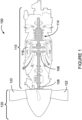
Figure 1 illustrates anaircraft powerplant 100 for an aircraft of a type preferably provided for use in subsonic flight, generally comprising anengine 110 and apropeller 120. Thepowerplant 100 generally comprises in serial flow communication thepropeller 120 attached to ashaft 108 and through which ambient air is propelled, acompressor section 114 for pressurizing the air, acombustor 116 in which the compressed air is mixed with fuel and ignited for generating an annular stream of hot combustion gases, and aturbine section 106 for extracting energy from the combustion gases driving the rotation of the propeller throughshaft 108. Thepropeller 120 converts rotary motion from theshaft 108 of theengine 110 to provide propulsive force for the aircraft, also known as thrust. Thepropeller 120 is variable-pitch propeller capable of generating forward and reverse thrust. Thepropeller 120 comprises two ormore propeller blades 122. A blade angle of thepropeller blades 122 may be adjusted. The blade angle may be referred to as a beta angle, an angle of attack or a blade pitch. Thepowerplant 100 may be implemented to comprise a single or multi-spool gas turbine engine, where theturbine section 106 is typically connected to thepropeller 120 through a reduction gearbox (RGB). - With reference to
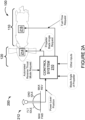
Figure 2A , there is illustrated asystem 200 for operating thepowerplant 100 in accordance with an embodiment. In this embodiment, acontrol system 210 receives a power lever or throttle position from apower lever 212 of the aircraft under control by a pilot or other operator of the aircraft. The power lever position is indicative of the type of thrust demanded by thepower lever 212. Several power lever positions can be selected, including those for (1) maximum forward thrust (MAX FWD), which is typically used during takeoff; (2) flight idle (FLT IDLE), which may be used in flight during approach or during taxiing on the ground; (3) ground idle (GND IDLE), at which thepropeller 120 is spinning, but providing very low thrust; (4) maximum reverse thrust (MAX REV), which is typically used at landing in order to slow the aircraft. Intermediate positions between the abovementioned positions can also be selected. The power lever positions may vary depending on practical implementations of thepower lever 212. In some embodiments, thepower lever 212 does not comprise a region for requesting reverse thrust. - The
control system 210 receives additional inputs pertaining to the operation of thepropeller 120,engine 110 and/or the aircraft. In the illustrated embodiment, thecontrol system 210 receives a blade angle of thepropeller 120. In some embodiments, thecontrol system 210 receives an aircraft status indicative of whether the aircraft is on-ground or in-flight. For example, the aircraft status may be a weight-on-wheels condition received from an aircraft computer. In some embodiments, thecontrol system 210 determines the aircraft status based on one or more of the additional inputs. In some embodiments, thecontrol system 210 receives a forward airspeed of the aircraft. The additional inputs may vary depending on practical implementations. In general, thecontrol system 210 is configured to control theengine 110 and thepropeller 120 based on the received inputs. Thecontrol system 210 controls theengine 110 by outputting a fuel flow request to anengine actuator 216 for adjusting engine fuel flow and controls thepropeller 120 by outputting a propeller blade angle request to apropeller actuator 214 for adjusting the blade angle of thepropeller 120. Theengine actuator 216 and/orpropeller actuator 214 may each be implemented as a torque motor, a stepper motor, or any other suitable actuator. Theengine actuator 216 may be implemented as one or more valves that regulate fuel flow from a fuel source to theengine 110. Thecontrol system 210 determines the fuel flow request for adjusting engine fuel flow and the propeller blade angle request for adjusting the blade angle of thepropeller 120 based on the received inputs. Thepropeller actuator 214 may control hydraulic oil pressure to adjust the blade angle based on the propeller blade angle request. In some embodiments, the propeller blade angle request is an oil flow request to set the propeller blade angle. Theengine actuator 216 can adjust the fuel flow to theengine 110 based on the fuel flow request. While theengine actuator 216 and thepropeller actuator 214 are illustrated as being part of theengine 110 and thepropeller 120, respectively, it should be understood that this is for illustrative purposes only and that theengine actuator 216 and/or thepropeller actuator 214 may, in some embodiments, be separate from thepowerplant 100. While thecontroller 210 is illustrated as separate from thepowerplant 100, it should be understood that this is for illustrative purposes only and that thecontroller 210 may, in some embodiments, be integrated with thepowerplant 100. - The
control system 210 is configured to receive a request to enable a mode for automated reverse thrust of the propeller 120 (referred to herein as the "automated reverse thrust mode"). The automated reverse thrust mode is a mode of thecontrol system 210 for operating theengine 110 and thepropeller 120 in a manner to cause the propeller to provide reverse thrust at landing without a direct request for reverse thrust from thepower lever 212. The request to enable the automated reverse thrust mode may be received in various manners, for example from an aircraft computer connected to a cockpit interface (e.g., an illuminated push-button) used to select and deselect the automated reverse thrust mode. Alternatively or in combination therewith, one or more of the power lever positions may correspond to a request for the automated reverse thrust mode. Thecontrol system 210 is configured to trigger reverse thrust of thepropeller 120 when the automated reverse thrust mode is enabled and when certain reverse thrust conditions have been met. - In accordance with some embodiments, the
control system 210 is configured to determine that the reverse thrust conditions are met when the aircraft is on-ground, a blade angle of thepropeller 120 is below a blade angle threshold and a position of thepower lever 212 is at a selected idle region of thepower lever 212. In some embodiments, the reverse thrust conditions are met when the aforementioned conditions are met and a forward airspeed of the aircraft is below a minimum forward speed threshold . - The selected idle region may be a range of the
power lever 212. For example, the selected idle region can be a range between the ground idle position and the flight idle position of thepower lever 212. In some embodiments, the range between the ground idle position and the flight idle position of thepower lever 212 is inclusive of the ground idle position and/or the flight idle position. The selected idle region may be a specific position of thepower lever 212. For example, the specific position may be the flight idle position of thepower lever 212. It should be appreciated that the selected idle region does not correspond to a region of thepower lever 212 normally used for requesting reverse thrust. - Triggering reverse thrust corresponds to any response mechanism(s) and/or action(s) to cause the propeller to provide reverse thrust. Triggering reverse thrust comprises the
control system 210 adjusting the blade angle of thepropeller 120 and adjusting the engine power by adjusting engine fuel flow to cause thepropeller 120 to provide reverse thrust. In some embodiments, thecontrol system 210 triggers reverse thrust by decreasing the blade angle of thepropeller 120 at a predetermined rate towards a full reverse blade angle and increasing engine power at a predetermined rate towards a full reverse power of theengine 110. When applicable, thecontrol system 210 reduces engine power and adjusts the blade angle of thepropeller 120 to stop thepropeller 120 from providing reverse thrust. - It should be appreciated that by triggering reverse thrust when the automated reverse thrust mode is enabled and when reverse thrust conditions have been met, reverse thrust occurs automatically without any direct request from the pilot (i.e., without the pilot moving the
power lever 212 into a reverse thrust regime of the power lever 212). It should further be appreciated that by not having the pilot move thepower lever 212 into a reverse thrust regime of thepower lever 212 to request reverse thrust, this prevents thepropeller 120 from inadvertently providing positive thrust. - With reference to
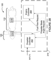
Figure 2B , thecontrol system 210 is illustrated in accordance with one or more embodiments. In this embodiment, apropeller controller 252 controls thepropeller 120 and anengine controller 254 controls theengine 110. Thepropeller controller 252 determines and outputs the propeller blade angle request and theengine controller 254 determines and outputs the fuel flow request. Thepropeller controller 252 receives the inputs (e.g., the power lever position, blade angle, aircraft status, forward airspeed and/or any other suitable inputs) and is in electronic communication with the engine controller for providing one or more of the received inputs to theengine controller 254. In some embodiments, theengine controller 254 additionally or alternatively receives the inputs (e.g., the power lever position, blade angle, aircraft status, forward airspeed and/or any other suitable inputs). In some embodiments, theengine controller 254 provides one or more of the received inputs to thepropeller controller 252. In some embodiments, thepropeller controller 252 may determine the blade angle of thepropeller 120 and provide the blade angle to theengine controller 254. In alternative embodiments, the functionalities of thepropeller controller 252 and theengine controller 254 may be implemented in a single controller. - To further illustrate automating of reverse thrust at landing of the aircraft, a specific and non-limiting example will now be described. When the aircraft is in-flight (e.g., during descent of the aircraft), the pilot enables the automated reverse thrust mode by pushing an automated reverse thrust mode push-button of the cockpit interface from OFF to ON. As the aircraft approaches the runway, the pilot sets the
power lever 212 at the flight idle position. When the aircraft touches down on the ground, the pilot maintains thepower lever 212 at the flight idle position. When all of the reverse thrust conditions have been met, and as the reverse thrust mode has been enabled, theengine controller 254 automatically adjusts the engine power and thepropeller controller 252 automatically adjusts the blade angle of thepropeller 120 such that there is a transition to maximum reverse power and maximum reverse blade angle, resulting in maximum reverse thrust. Once conditions for ending reverse thrust exist, theengine controller 254 reduces the engine power and thepropeller controller 252 adjusts the blade angle of thepropeller 120 to correspond to the engine power and blade angle for the ground idle position in order for thepropeller 120 to stop providing reverse thrust. - With reference to
Figure 2C , in some embodiments, each of thepropeller controller 252 and theengine controller 254 comprise two or more channels, such as channels A and B. For each of thecontrollers - When a channel is in standby, the channel is functional and able to take over control when needed. If it is determined that the presently active channel or one of the
actuators - In the illustrated embodiment, each channel A, B of the
propeller controller 252 receives the power lever position from at least onesensor 224. Each channel A, B of thepropeller controller 252 receives the power lever position from at least one sensor 222 (or aircraft computer). Each channel A, B of thepropeller controller 252 receives the blade angle of thepropeller 120 from at least one sensor 224 (or aircraft computer). Each channel A, B of thepropeller controller 252 receives the aircraft status from at least one sensor 226 (or aircraft computer). Each channel A, B of thepropeller controller 252 also receives the forward airspeed from at least one sensor 228 (or aircraft computer). One or more of thesensors propeller controller 252. In this example, theengine controller 254 receives the blade angle, the power lever position, aircraft status and forward airspeed from thepropeller controller 254. In alternative embodiments, theengine controller 254 receives the blade angle, the power lever position, aircraft status and forward airspeed from sensors, such as thesensors engine 110 based on the fuel flow request from the active channel of theengine controller 254. In alternate embodiments, the functionalities of thepropeller controller 252 and theengine controller 254 ofFigure 2C may be implemented in a single dual-channel controller. - With reference to
Figure 3A , there is illustrated a flowchart of amethod 300 for operating a powerplant, such as thepowerplant 100. Themethod 300 may be performed by thecontrol system 210, theengine controller 254,propeller controller 252 or a combination thereof. Atstep 302, a request to enable the mode for automated reverse thrust is received. - At
step 304, themethod 300 comprises determining that reverse thrust conditions have been met. In some embodiments, the reverse thrust conditions comprise a selected idle region of thepower lever 212. In some embodiments, the reverse thrust conditions comprise a blade angle of thepropeller 120 being below a blade angle threshold. In some embodiments, the reverse thrust conditions comprise an aircraft on-ground condition. One, two, or all three of these conditions may be used to determine that the reverse thrust conditions have been met. In some embodiments, one, two, or all three of these conditions are combined with other conditions. - In accordance with some embodiments, the reverse thrust conditions have been met when the aircraft is on-ground, a blade angle of the
propeller 120 is below a blade angle threshold and a position of thepower lever 212 is at a selected idle region of thepower lever 212. The corresponding blade angle for the blade angle threshold may vary depending on practical implementations. For example, the blade angle threshold may correspond to a minimum blade angle at which thepropeller 120 can provide reverse thrust. In some embodiments, the reverse thrust conditions have been met when the aircraft is on-ground, the blade angle of thepropeller 120 is below the blade angle threshold, the position of thepower lever 212 is at the selected idle region of thepower lever 212 and a forward airspeed of the aircraft is below a minimum forward speed threshold. The minimum forward speed threshold corresponds to the minimum airspeed of aircraft for the enabling of automatic reverse thrust and The minimum forward speed threshold is below a minimum in-flight airspeed of the aircraft. The aircraft may be considered on-ground when a weight-on-wheels condition of the aircraft is met. Other means of determining on-ground/in-flight status of the aircraft may also be used. For example, the aircraft may be considered to be on-ground when the forward airspeed of the aircraft is below the in-flight minimum speed threshold. Accordingly, in some embodiments, the reverse thrust condition for the aircraft to be on-ground is met when the forward airspeed of the aircraft is below the minimum forward speed threshold. The reverse thrust conditions may be checked in any suitable order or concurrently. If one of the reverse thrust conditions is not met (e.g., if the aircraft is in-flight), the method may stop checking the other reverse thrust conditions. - The power lever position, the blade angle of the
propeller 120, the aircraft status and/or the forward airspeed may be obtained atstep 304. Each of the power lever position, the blade angle of thepropeller 120, the aircraft status and/or the forward airspeed may be received from a respective measuring device comprising one or more sensors. In some embodiments, the power lever position, the blade angle of thepropeller 120, the aircraft status and/or the forward airspeed are obtained via existing components as part of engine control and/or operation. For example, the power lever position, the blade angle of thepropeller 120, the aircraft status and/or the forward airspeed may be provided from one of an engine controller, a propeller controller or an aircraft computer. The power lever position, the blade angle of thepropeller 120, the aircraft status and/or the forward airspeed may be dynamically obtained in real time, may be obtained regularly in accordance with any predetermined time interval, or may be obtained irregularly. - At
step 306, reverse thrust of thepropeller 120 is triggered when the mode for automated reverse thrust is enabled and when the reverse thrust conditions have been met. In some embodiments,step 306 comprises applying reverse thrust for a predetermined or dynamically determined period of time. The predetermined period of time may be any suitable time period. In some embodiments, the period of time may be determined dynamically based on the weight of the aircraft or using one or more other parameters. - In some embodiments, the
method 300 comprises atstep 308 ending the reverse thrust when a forward airspeed of the aircraft is below a ground minimum speed threshold. The ground minimum speed threshold corresponds to any suitable flight speed indicative that the application of reverse thrust can be stopped. For example, the ground minimum speed threshold may be the taxiing speed of the aircraft. In some embodiments, themethod 300 comprises atstep 310 ending the reverse thrust when thepower lever 212 is moved out of the selected idle region. In some embodiments, themethod 300 comprises atstep 312 ending the reverse thrust in response to a request to disable the mode for automated reverse thrust. - With reference to
Figure 3B there is shown aflowchart 320 illustrating the logic of thecontrol system 210 for operating thepowerplant 100, in accordance with a specific and non-limiting embodiment. In some embodiments, thecontrol system 210 sets the automated reverse thrust mode to various states: off, standby, armed, activated and deactivated. At 322, the automated reverse thrust mode is off. At 324, an automated reverse thrust mode push-button is actuated from OFF to ON. When the push-button is actuated from OFF to ON, a request to enable reverse thrust is provided to thecontrol system 210. At 326, it is determined if the aircraft is in-flight. If the aircraft is not in-flight (i.e., on-ground), then the automated reverse thrust mode remains turned off. If the aircraft is in-flight, then at 328 it is determined if thepower lever 212 is above the flight idle position. If thepower lever 212 is below or at the flight idle position, then the automated reverse thrust mode remains turned off. If thepower lever 212 is above the flight idle position, then the automated reverse thrust mode is put into standby at 330. In some embodiments, an indicator is outputted to cause a display device to indicate that the automated reverse thrust mode is in standby. - At 332, it is determined if the aircraft is on-ground. If the aircraft is not on-ground (i.e., in-flight), then the automated reverse thrust mode remains in standby and 332 is repeated. In other words, the logic waits for the aircraft to be on-ground. If the aircraft is on-ground, then at 334 it is determined if the position of the
power lever 212 is between the ground idle and the flight idle positions. In this example, the selected idle region is between the ground idle and the flight idle position, inclusive of the ground idle and flight idle positions. If the position of thepower lever 212 is outside of the selected idle region, then the automated reverse thrust mode is turned off. If the position of thepower lever 212 is within the selected idle region, then at 336 it is determined if the push-button is still ON. If the push-button is OFF, then the automated reverse thrust mode is turned off. If the push-button is still ON, then at 338 the automated reverse thrust mode is armed. In some embodiments, an indicator is outputted to cause a display device to indicate that the automated reverse thrust mode is armed. The order of 332, 334 and 336 may vary depending on practical implementations. In some embodiments, one or more of 332, 334 and 336 may be combined. - At 339, the armed conditions of 332, 334, 336 are assessed to determine if the armed conditions are still met. If one of the armed conditions are not met, then the automated reverse thrust mode is set to off. In other words, while the automated reverse thrust mode is armed, the pilot can disable the automatic reverse thrust mode by increasing the position of the
power lever 212 above the flight idle position, decreasing the position of thepower lever 212 below the ground idle position, or deselects the push-button from ON to OFF. When the automatic reverse thrust mode is disabled, the engine power and blade angle of thepropeller 120 are set as function of the position of thepower lever 212, as set by the pilot. - If the armed conditions are met, then at 340, it is determined if the blade angle of the
propeller 120 is below the blade angle threshold. If the blade angle of thepropeller 120 is not below the blade angle threshold, then the automated reverse thrust mode remains armed and then 339 is repeated. In other words, when the blade angle is not below the blade angle threshold, the logic waits for blade angle to become below the blade angle threshold. If the blade angle of thepropeller 120 is below the blade angle threshold, then at 342 it is determined if the airspeed of the aircraft is below the minimum forward speed threshold. If the airspeed is not below the minimum forward speed threshold, then the automated reverse thrust mode remains armed and then 339 is repeated. In otherwords, when the airspeed is not below the minimum forward speed threshold, the logic waits for the airspeed to be below the minimum forward speed threshold. If the airspeed is below the minimum forward speed threshold, then at 344 the automated reverse thrust mode is activated. The order of 339, 340 and 342 may vary depending on practical implementations. In some embodiments, one or more of 339, 340 and 342 may be combined. - In some embodiments, 342 may be omitted. In some embodiments, the automated reverse thrust mode is activated in response to the reverse thrust conditions of 339, 340 and 342 being met. In some embodiments, an indicator is outputted to cause a display device to indicate that the automated reverse thrust mode is activated.
- At 346, it is determined if the reverse thrust conditions of 339, 340 and 342 have been met. If the reverse thrust conditions are not met, then the automated reverse thrust mode is turned off. If the reverse thrust conditions have been met, then reverse thrust is triggered at 347. The reverse thrust is provided while the reverse thrust conditions remain met. In other words, the pilot may disable the automated reverse thrust by causing one of the reverse thrust condition to no longer be met. When the automatic reverse thrust mode is disabled, the engine power and blade angle of the
propeller 120 are set as function of the position of thepower lever 212, as set by the pilot. - At 348, it is determined if the forward airspeed of the aircraft is below the ground minimum speed threshold. Once the forward airspeed of the aircraft is below the ground minimum speed threshold, at 350, a transition to ground idle settings occurs and reverse thrust is ended to deactivate the automated reverse thrust mode. In some embodiments, an indicator is outputted to cause a display device to indicate that the automated reverse thrust mode is deactivated. In alternative embodiments, 348 may be omitted and the reverse thrust applied at 347 may be applied for a predetermined period of time or for a period of time determined based on the weight of the aircraft.
- In some embodiments, when the automated reverse thrust mode is deactivated, the
propeller controller 252 automatically sets the blade angle of thepropeller 120 to the blade angle associated with the ground idle position and theengine controller 252 sets the engine power to the engine power associated with the ground idle position, even though the position of thepower lever 212 may not be set at the ground idle position (e.g., the position of thepower lever 212 could be at the flight idle position). - At 352, it is determined if the position of the
power lever 212 is above ground idle position or below flight idle position. The pilot may manually move thepower lever 212 to the ground idle position after reverse thrust has stopped. In some embodiments, thepower lever 212 is automatically moved to the ground idle position by an actuator in response to ending of the reverse thrust. If thepower lever 212 is below the ground idle or above flight idle position, the automated reverse thrust mode is turned off. If thepower lever 212 is still in between ground idle and flight idle position, at 354 it is determined if the push-button is OFF. The pilot may push the push-button to the OFF state after reverse thrust has ended or in order to cause the reverse thrust to stop. If the push-button is OFF, the automated reverse thrust mode is turned off. If push-button is not OFF, the logic waits until either the push-button is OFF or thepower lever 212 is at the ground idle position. The order of 352 and 354 may vary depending on practical implementations. In some embodiments, 352 and 354 may be combined. When theflowchart 320 returns to 322, the push-button would automatically be placed into OFF. In some embodiments, an indicator is outputted to cause a display device to indicate that the automated reverse thrust mode is turned off. - With reference to
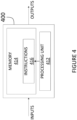
Figure 4 , an example of acomputing device 400 is illustrated. Thecontrol system 210 may be implemented with one ormore computing devices 400. For example, each of thepropeller controller 252 and theengine controller 254 may be implemented by aseparate computing device 400. Thecomputing device 400 comprises aprocessing unit 412 and amemory 414 which has stored therein computer-executable instructions 416. Theprocessing unit 412 may comprise any suitable devices configured to implement themethod 300 such thatinstructions 416, when executed by thecomputing device 400 or other programmable apparatus, may cause the functions/acts/steps performed as part of themethod 300 as described herein to be executed. Theprocessing unit 412 may comprise, for example, any type of general-purpose microprocessor or microcontroller, a digital signal processing (DSP) processor, a central processing unit (CPU), an integrated circuit, a field programmable gate array (FPGA), a reconfigurable processor, other suitably programmed or programmable logic circuits, or any combination thereof. - The
memory 414 may comprise any suitable known or other machine-readable storage medium. Thememory 414 may comprise non-transitory computer readable storage medium, for example, but not limited to, an electronic, magnetic, optical, electromagnetic, infrared, or semiconductor system, apparatus, or device, or any suitable combination of the foregoing. Thememory 414 may include a suitable combination of any type of computer memory that is located either internally or externally to device, for example random-access memory (RAM), read-only memory (ROM), compact disc read-only memory (CDROM), electro-optical memory, magneto-optical memory, erasable programmable read-only memory (EPROM), and electrically-erasable programmable read-only memory (EEPROM), Ferroelectric RAM (FRAM) or the like.Memory 414 may comprise any storage means (e.g., devices) suitable for retrievably storing machine-readable instructions 416 executable by processingunit 412. Note that thecomputing device 400 can be implemented as part of a full-authority digital engine controls (FADEC) or other similar device, including electronic engine control (EEC), engine control unit (ECU), electronic propeller control, propeller control unit, and the like. - The methods and systems for operating an engine described herein may be implemented in a high level procedural or object oriented programming or scripting language, or a combination thereof, to communicate with or assist in the operation of a computer system, for example the
computing device 400. Alternatively, the methods and systems for operating an engine may be implemented in assembly or machine language. The language may be a compiled or interpreted language. Program code for implementing the methods and systems for operating an engine may be stored on a storage media or a device, for example a ROM, a magnetic disk, an optical disc, a flash drive, or any other suitable storage media or device. The program code may be readable by a general or special-purpose programmable computer for configuring and operating the computer when the storage media or device is read by the computer to perform the procedures described herein. Embodiments of the methods and systems for operating an engine may also be considered to be implemented by way of a non-transitory computer-readable storage medium having a computer program stored thereon. The computer program may comprise computer-readable instructions which cause a computer, or more specifically theprocessing unit 412 of thecomputing device 400, to operate in a specific and predefined manner to perform the functions described herein, for example those described in themethod 300. - Computer-executable instructions may be in many forms, including program modules, executed by one or more computers or other devices. Generally, program modules include routines, programs, objects, components, data structures, etc., that perform particular tasks or implement particular abstract data types. Typically the functionality of the program modules may be combined or distributed as desired in various embodiments.
- The above description is meant to be exemplary only, and one skilled in the art will recognize that changes may be made to the embodiments described without departing from the scope of the invention disclosed. Still other modifications which fall within the scope of the present invention will be apparent to those skilled in the art, in light of a review of this disclosure.
- Various aspects of the methods and systems for operating an engine may be used in a variety of arrangements not specifically discussed in the embodiments described in the foregoing and is therefore not limited in its application to the details and arrangement of components set forth in the foregoing description or illustrated in the drawings. Although particular embodiments have been shown and described, it will be obvious to those skilled in the art that changes and modifications may be made without departing from this invention in its broader aspects. The scope of the following claims should not be limited by the embodiments set forth in the examples.
Claims (15)
- A method for operating an aircraft powerplant (100) comprising an engine (110) coupled to a variable-pitch propeller (120) capable of generating forward and reverse thrust, the method comprising:receiving a request to enable a mode for automated reverse thrust;determining that reverse thrust conditions have been met when the aircraft is on-ground, a blade angle of the propeller (120) is below a blade angle threshold and a position of a power lever (212) is at a selected idle region of the power lever (212); andtriggering reverse thrust of the propeller (120) when the mode for automated reverse thrust is enabled and the reverse thrust conditions have been met.
- The method of claim 1, wherein the selected idle region is a range between a ground idle position and a flight idle position of the power lever (212), inclusive of the ground idle position and the flight idle position.
- The method of claim 1, wherein the selected idle region is a flight idle position of the power lever (212).
- The method of any of claims 1 to 3, further comprising determining that the reverse thrust conditions have been met when a forward airspeed of the aircraft is below a minimum forward speed threshold.
- The method of any of claims 1 to 4, wherein triggering reverse thrust comprises decreasing the blade angle of the propeller (120) at a predetermined rate towards a full reverse blade angle and increasing engine power at a predetermined rate towards a full reverse power of the engine (110).
- The method of any of claims 1 to 5, wherein triggering reverse thrust of the propeller (120) comprises applying reverse thrust for a period of time determined based on a weight of the aircraft.
- The method of any of claims 1 to 6, further comprising ending the reverse thrust when a forward airspeed of the aircraft is below a ground minimum speed threshold, and/or when the power lever (212) is moved out of the selected idle region, and/or in response to receiving a request to disable the mode for automated reverse thrust.
- A system (200) for operating an aircraft powerplant (100) comprising an engine (110) coupled to a variable-pitch propeller (120) capable of generating forward and reverse thrust, the system (200) comprising:at least one processing unit (412); andat least one non-transitory computer-readable memory (414) having stored thereon program instructions (416) executable by the processing unit (412) for:receiving a request to enable a mode for automated reverse thrust;determining that reverse thrust conditions have been met when the aircraft is on-ground, a blade angle of the propeller (120) is below a blade angle threshold and a position of a power lever (212) is at a selected idle region of the power lever (212); andtriggering reverse thrust of the propeller (120) when the mode for automated reverse thrust is enabled and the reverse thrust conditions have been met.
- The system (200) of claim 8, wherein the selected idle region is a range between a ground idle position and a flight idle position of the power lever (212), inclusive of the ground idle position and the flight idle position.
- The system (200) of claim 8, wherein the selected idle region is a flight idle position of the power lever (212).
- The system (200) of any of claims 8 to 10, wherein the program instructions (416) are further executable by the at least one processing unit (412) for determining that the reverse thrust conditions have been met when a forward airspeed of the aircraft is below a minimum forward speed threshold.
- The system (200) of any of claims 8 to 11, wherein triggering reverse thrust comprises decreasing the blade angle of the propeller (120) at a predetermined rate towards a full reverse blade angle and increasing engine power at a predetermined rate towards a full reverse power of the engine (110).
- The system (200) of any of claims 8 to 12, wherein triggering reverse thrust of the propeller (120) comprises applying reverse thrust for a period of time determined based on a weight of the aircraft.
- The system (200) of any of claims 8 to 13, wherein the program instructions (416) are further executable by the at least one processing unit (412) for ending the reverse thrust when a forward airspeed of the aircraft is below a ground minimum speed threshold, and/or when the power lever (212) is moved out of the selected idle region.
- The system (200) of any of claims 8 to 14, wherein the program instructions (416) are further executable by the at least one processing unit (412) for ending the reverse thrust in response to receiving a request to disable the mode for automated reverse thrust.
Applications Claiming Priority (1)
| Application Number | Priority Date | Filing Date | Title |
|---|---|---|---|
| US16/371,608 US11414175B2 (en) | 2019-04-01 | 2019-04-01 | Method and system for operating an aircraft powerplant |
Publications (2)
| Publication Number | Publication Date |
|---|---|
| EP3718882A1 EP3718882A1 (en) | 2020-10-07 |
| EP3718882B1 true EP3718882B1 (en) | 2023-05-31 |
Family
ID=70154334
Family Applications (1)
| Application Number | Title | Priority Date | Filing Date |
|---|---|---|---|
| EP20167610.3A Active EP3718882B1 (en) | 2019-04-01 | 2020-04-01 | Method and system for operating an aircraft powerplant |
Country Status (3)
| Country | Link |
|---|---|
| US (1) | US11414175B2 (en) |
| EP (1) | EP3718882B1 (en) |
| CA (1) | CA3077511A1 (en) |
Families Citing this family (6)
| Publication number | Priority date | Publication date | Assignee | Title |
|---|---|---|---|---|
| US11852083B2 (en) | 2018-11-23 | 2023-12-26 | Pratt & Whitney Canada Corp. | Engine and propeller control system |
| US11408357B2 (en) * | 2018-11-23 | 2022-08-09 | Pratt & Whitney Canada Corp. | Engine and propeller control system |
| US11597508B2 (en) | 2021-05-13 | 2023-03-07 | Beta Air, Llc | Aircraft having reverse thrust capabilities |
| FR3132279B1 (en) * | 2022-02-01 | 2024-01-12 | Safran Aircraft Engines | Braking process for an aircraft turbomachine |
| US20230250766A1 (en) * | 2022-02-04 | 2023-08-10 | Nicolas Des Roches-Dionne | Method and system of operating an airplane engine |
| US11933248B1 (en) | 2022-12-09 | 2024-03-19 | Pratt & Whitney Canada Corp. | Reverse thrust system and method |
Family Cites Families (67)
| Publication number | Priority date | Publication date | Assignee | Title |
|---|---|---|---|---|
| US4648798A (en) * | 1985-05-01 | 1987-03-10 | The Cessna Aircraft Company | Controllable pitch aircraft propeller |
| US4958289A (en) * | 1988-12-14 | 1990-09-18 | General Electric Company | Aircraft propeller speed control |
| US5029091A (en) * | 1989-04-11 | 1991-07-02 | United Technologies Corporation | Ground mode control of aircraft propeller speed and pitch |
| US5213471A (en) | 1990-09-04 | 1993-05-25 | General Electric Company | Propeller pitch control |
| US6311928B1 (en) | 2000-01-05 | 2001-11-06 | Stage Iii Technologies, L.C. | Jet engine cascade thrust reverser for use with mixer/ejector noise suppressor |
| FR2830051B1 (en) | 2001-09-27 | 2003-11-07 | Hurel Hispano Le Havre | LOCKING SYSTEM ON A GRID DRIVE INVERTER |
| FR2857468B1 (en) * | 2003-07-08 | 2005-09-30 | Airbus France | SYSTEM FOR AIDING THE CONTROL OF THE DECELERATION OF AN AIRCRAFT RUNNING ON THE GROUND |
| US7946106B2 (en) | 2004-06-29 | 2011-05-24 | Aircelle | Device for actuating mobile cowls equipping a thrust reverser |
| US7797095B2 (en) | 2005-02-23 | 2010-09-14 | Aviation Safety Technologies, Llc | Method and device of calculating aircraft braking friction and other relating landing performance parameters based on the data received from aircraft's on board flight data management system |
| US7559507B2 (en) | 2005-06-27 | 2009-07-14 | The Boeing Company | Thrust reversers including locking assemblies for inhibiting deflection |
| US8651811B2 (en) | 2005-11-16 | 2014-02-18 | Hamilton Sundstrand | Control logic for a propeller system |
| US7586422B2 (en) | 2006-08-02 | 2009-09-08 | The Boeing Company | Determination of runway landing conditions |
| US8155876B2 (en) | 2006-09-07 | 2012-04-10 | The Boeing Company | Systems and methods for controlling aircraft electrical power |
| FR2906066B1 (en) | 2006-09-15 | 2008-12-19 | Thales Sa | METHOD OF ESTIMATING THE POINT OF TOUCHING WHEELS OF AN AIRCRAFT ON A LANDING TRAIL AND THE DISTANCE TO BE FOLLOWED FROM THE POINT OF TOUCH TO REACH A CONTROLLED SPEED. |
| US7818100B2 (en) | 2007-04-03 | 2010-10-19 | The Boeing Company | System and method for optimized runway exiting |
| FR2930973B1 (en) | 2008-05-06 | 2010-04-23 | Airbus France | METHOD AND DEVICE FOR IMPLEMENTING THE THRUST INVERTERS OF AN AIRCRAFT |
| US9043050B2 (en) | 2008-08-13 | 2015-05-26 | The Boeing Company | Programmable reverse thrust detent system and method |
| FR2936079B1 (en) | 2008-09-16 | 2010-09-17 | Thales Sa | METHOD FOR MONITORING THE LANDING PHASE OF AN AIRCRAFT |
| GB0821783D0 (en) | 2008-12-01 | 2009-01-07 | Rolls Royce Plc | Blade pitch control system |
| FR2941554B1 (en) | 2009-01-29 | 2011-04-01 | Airbus France | METHOD AND DEVICE FOR AIDING THE CONTROL OF AN AIRCRAFT DURING A LANDING PHASE |
| GB0905560D0 (en) | 2009-04-01 | 2009-05-13 | Rolls Royce Plc | An electrical actuator arrangement |
| FR2959316B1 (en) | 2010-04-21 | 2012-05-18 | Airbus Operations Sas | METHOD AND DEVICE FOR AUTOMATICALLY ESTIMATING AIR SPEED OF AN AIRCRAFT |
| US8560150B1 (en) | 2010-07-07 | 2013-10-15 | The Boeing Company | Methods and systems for landing decision point |
| FR2967397B1 (en) | 2010-11-16 | 2012-11-16 | Snecma | DEVICE FOR PASSING A REVERSE PROPELLER COMPRISING A ACTUATOR ACTING ON A MANETON |
| FR2978801B1 (en) | 2011-08-05 | 2016-03-04 | Snecma | METHOD FOR MONITORING THE LOCKING MEANS OF AN ELECTRICAL PUSH REVERSING SYSTEM FOR TURBOMACHINE |
| US8464511B1 (en) | 2012-01-06 | 2013-06-18 | Hamilton Sundstrand Corporation | Magnetically coupled contra-rotating propulsion stages |
| US9278674B2 (en) | 2012-01-18 | 2016-03-08 | Engineered Arresting Systems Corporation | Vehicle operator display and assistive mechanisms |
| US9120559B2 (en) | 2012-04-18 | 2015-09-01 | Hamilton Sundstrand Corporation | Propeller blade pitch actuation system |
| FR2990248B1 (en) | 2012-05-04 | 2015-09-25 | Aircelle Sa | CONTROL SYSTEM FOR THRUST INVERTER |
| US9164505B1 (en) | 2012-05-22 | 2015-10-20 | The Boeing Company | Automatic rejected takeoff system |
| GB2510634B (en) | 2013-02-12 | 2015-03-04 | Ge Aviat Systems Ltd | Methods of monitoring hydraulic fluid levels in an aircraft |
| US9296488B2 (en) | 2013-03-06 | 2016-03-29 | 3Rd Millennium Solutions, Inc. | Aircraft braking early warning system |
| US9163583B2 (en) | 2013-05-01 | 2015-10-20 | Rohr, Inc. | System, apparatus, and method for thrust vectoring |
| FR3006292B1 (en) | 2013-05-30 | 2017-01-27 | Eurocopter France | ROTARY SAILING GIRAVION WITH A PLURALITY OF PROPELLERS |
| EP2840022B1 (en) | 2013-08-21 | 2016-04-27 | Gatewing NV | An unmanned aircraft with failsafe system |
| CA2925870C (en) * | 2013-10-11 | 2019-05-14 | Unison Industries, Llc | Method and apparatus for controlling a turboprop engine |
| US9821901B2 (en) | 2013-11-21 | 2017-11-21 | Pratt & Whitney Canada Corp. | System and method for electronic propeller blade angle position feedback |
| CN103760906B (en) | 2014-01-29 | 2016-06-01 | 天津大学 | Neural network and non-linear continuous depopulated helicopter attitude control method |
| US9412210B2 (en) | 2014-03-07 | 2016-08-09 | Hydro-Aire, Inc. | Method of reporting runway condition using brake control system |
| US9430948B2 (en) | 2014-04-16 | 2016-08-30 | The Boeing Company | Landing alerts for preventing runway excursions |
| FR3022340B1 (en) | 2014-06-16 | 2016-07-15 | Thales Sa | METHOD AND DEVICE FOR DETERMINING AN AIRCRAFT CONTROL INSTRUCTION, COMPUTER PROGRAM PRODUCT AND ASSOCIATED AIRCRAFT |
| US9708073B2 (en) | 2014-08-22 | 2017-07-18 | Rohr, Inc. | Automatic deflection limiting latches for a thrust reverser |
| EP3186998A4 (en) | 2014-08-29 | 2018-09-26 | Zunum Aero, Inc. | System and methods for implementing regional air transit network using hybrid-electric aircraft |
| US9845145B2 (en) * | 2014-09-30 | 2017-12-19 | General Electric Company | Method and system for model based control for variable pitch fan engines and turbo-shaft, turbo-propeller engines |
| EP3018054B1 (en) * | 2014-11-07 | 2019-01-02 | Airbus Defence and Space, S.A. | Method for controlling an aircraft propeller system during thrust reversal |
| US9874176B2 (en) | 2015-01-14 | 2018-01-23 | The Boeing Company | Methods and apparatus to vary reverse thrust of aircraft engines |
| US9951718B2 (en) | 2015-02-19 | 2018-04-24 | Rohr, Inc. | Automatic bifurcation latch systems for a thrust reverser |
| FR3037108B1 (en) | 2015-06-02 | 2017-06-09 | Aircelle Sa | THRUST INVERTER FOR AIRCRAFT TURBO BOREHOLE |
| US9920695B2 (en) | 2015-06-22 | 2018-03-20 | Exhaustless Inc. | Thrust recovery in airplanes |
| US9771878B2 (en) | 2015-10-19 | 2017-09-26 | General Electric Company | Thrust scheduling method for variable pitch fan engines and turbo-shaft, turbo-propeller engines |
| US20170145956A1 (en) | 2015-11-20 | 2017-05-25 | General Electric Company | Thrust reverse feature control |
| FR3049265B1 (en) | 2016-03-24 | 2019-09-13 | Airbus Operations | METHOD AND DEVICE FOR DISPLAYING A HELP SYMBOL FOR AIDING AN AIRCRAFT DURING A LANDING PHASE |
| GB201607576D0 (en) | 2016-04-29 | 2016-06-15 | Novus Comm Ltd | Tracking system |
| EP3351772B1 (en) | 2017-01-20 | 2022-05-18 | GE Avio S.r.l. | Control system and method for managing a reverse-mode operation in a gas turbine engine |
| US10288007B2 (en) | 2017-02-02 | 2019-05-14 | Woodward, Inc. | Thrust reverser flow limiting valve |
| FR3064601B1 (en) | 2017-03-30 | 2021-01-01 | Safran Nacelles | TURBOREACTOR NACELLE CONNECTED TO THE FUSELAGE OF AN AIRCRAFT, AND PROPULSION ASSEMBLY |
| US10343786B2 (en) | 2017-06-28 | 2019-07-09 | General Electric Company | System and method of operating a ducted fan propulsion system during aircraft taxi |
| US10119495B1 (en) | 2017-06-28 | 2018-11-06 | General Electric Company | System and method of operating a ducted fan propulsion system inflight |
| US10831198B2 (en) * | 2017-08-18 | 2020-11-10 | The Boeing Company | Process and machine for making a runway extension speed for an aircraft |
| US10823113B2 (en) * | 2017-08-21 | 2020-11-03 | Pratt & Whitney Canada Corp. | Method and system for limiting power of an engine |
| US10429856B2 (en) | 2017-09-07 | 2019-10-01 | Embraer S.A. | Safe takeoff system |
| US10543909B2 (en) | 2017-09-11 | 2020-01-28 | Goodrich Corporation | System and method for aircraft electric taxi brake optimization |
| US11085395B2 (en) | 2017-12-22 | 2021-08-10 | Airbus Operations S.A.S. | Nacelle system and methods of operation |
| US10378452B1 (en) | 2018-02-26 | 2019-08-13 | The Boeing Company | Hybrid turbine jet engines and methods of operating the same |
| US20190279439A1 (en) | 2018-03-06 | 2019-09-12 | General Electric Company | Facilitating capturing aircraft flight segment |
| US10794327B2 (en) | 2018-03-21 | 2020-10-06 | Honeywell International Inc. | Systems and methods for thrust reverser with temperature and fluid management |
| US11098649B2 (en) | 2018-07-19 | 2021-08-24 | The Boeing Company | Self-regulating back-side pressurization system for thermal insulation blankets |
-
2019
- 2019-04-01 US US16/371,608 patent/US11414175B2/en active Active
-
2020
- 2020-03-31 CA CA3077511A patent/CA3077511A1/en active Pending
- 2020-04-01 EP EP20167610.3A patent/EP3718882B1/en active Active
Also Published As
| Publication number | Publication date |
|---|---|
| CA3077511A1 (en) | 2020-10-01 |
| EP3718882A1 (en) | 2020-10-07 |
| US20200307774A1 (en) | 2020-10-01 |
| US11414175B2 (en) | 2022-08-16 |
Similar Documents
| Publication | Publication Date | Title |
|---|---|---|
| EP3718882B1 (en) | Method and system for operating an aircraft powerplant | |
| US11408357B2 (en) | Engine and propeller control system | |
| US20200232395A1 (en) | Method and system for operating a gas turbine engine coupled to an aircraft propeller | |
| US20200362723A1 (en) | System and method for detecting an uncommanded or uncontrollable high thrust event in an aircraft | |
| US10823113B2 (en) | Method and system for limiting power of an engine | |
| EP3369660B1 (en) | System and method for testing control logic for a propeller of a gas turbine engine | |
| EP3738875B1 (en) | Method and system for operating a rotorcraft engine | |
| US11313286B2 (en) | Integrated propeller and engine controller | |
| EP3670876B1 (en) | System and method for operating a gas turbine engine coupled to an aircraft propeller | |
| EP3656661B1 (en) | Integral propeller and engine controller | |
| CA3002287A1 (en) | Detection of uncommanded and uncontrollable high thrust events | |
| CA3077906A1 (en) | Method and system for feathering a propeller | |
| US11852083B2 (en) | Engine and propeller control system | |
| EP3741665A1 (en) | Method and system for operating an aircraft powerplant | |
| US11719167B2 (en) | Operating a turboprop engine for in-flight restart | |
| US20210102504A1 (en) | Method and system for operating an aircraft powerplant |
Legal Events
| Date | Code | Title | Description |
|---|---|---|---|
| PUAI | Public reference made under article 153(3) epc to a published international application that has entered the european phase |
Free format text: ORIGINAL CODE: 0009012 |
|
| STAA | Information on the status of an ep patent application or granted ep patent |
Free format text: STATUS: THE APPLICATION HAS BEEN PUBLISHED |
|
| AK | Designated contracting states |
Kind code of ref document: A1 Designated state(s): AL AT BE BG CH CY CZ DE DK EE ES FI FR GB GR HR HU IE IS IT LI LT LU LV MC MK MT NL NO PL PT RO RS SE SI SK SM TR |
|
| AX | Request for extension of the european patent |
Extension state: BA ME |
|
| STAA | Information on the status of an ep patent application or granted ep patent |
Free format text: STATUS: REQUEST FOR EXAMINATION WAS MADE |
|
| 17P | Request for examination filed |
Effective date: 20210407 |
|
| RBV | Designated contracting states (corrected) |
Designated state(s): AL AT BE BG CH CY CZ DE DK EE ES FI FR GB GR HR HU IE IS IT LI LT LU LV MC MK MT NL NO PL PT RO RS SE SI SK SM TR |
|
| RIC1 | Information provided on ipc code assigned before grant |
Ipc: F02C 9/58 20060101ALI20220815BHEP Ipc: B64C 11/30 20060101AFI20220815BHEP |
|
| GRAP | Despatch of communication of intention to grant a patent |
Free format text: ORIGINAL CODE: EPIDOSNIGR1 |
|
| STAA | Information on the status of an ep patent application or granted ep patent |
Free format text: STATUS: GRANT OF PATENT IS INTENDED |
|
| INTG | Intention to grant announced |
Effective date: 20221005 |
|
| GRAJ | Information related to disapproval of communication of intention to grant by the applicant or resumption of examination proceedings by the epo deleted |
Free format text: ORIGINAL CODE: EPIDOSDIGR1 |
|
| STAA | Information on the status of an ep patent application or granted ep patent |
Free format text: STATUS: REQUEST FOR EXAMINATION WAS MADE |
|
| GRAP | Despatch of communication of intention to grant a patent |
Free format text: ORIGINAL CODE: EPIDOSNIGR1 |
|
| STAA | Information on the status of an ep patent application or granted ep patent |
Free format text: STATUS: GRANT OF PATENT IS INTENDED |
|
| INTC | Intention to grant announced (deleted) | ||
| GRAS | Grant fee paid |
Free format text: ORIGINAL CODE: EPIDOSNIGR3 |
|
| INTG | Intention to grant announced |
Effective date: 20230310 |
|
| GRAA | (expected) grant |
Free format text: ORIGINAL CODE: 0009210 |
|
| STAA | Information on the status of an ep patent application or granted ep patent |
Free format text: STATUS: THE PATENT HAS BEEN GRANTED |
|
| AK | Designated contracting states |
Kind code of ref document: B1 Designated state(s): AL AT BE BG CH CY CZ DE DK EE ES FI FR GB GR HR HU IE IS IT LI LT LU LV MC MK MT NL NO PL PT RO RS SE SI SK SM TR |
|
| REG | Reference to a national code |
Ref country code: GB Ref legal event code: FG4D Ref country code: CH Ref legal event code: EP |
|
| REG | Reference to a national code |
Ref country code: DE Ref legal event code: R096 Ref document number: 602020011223 Country of ref document: DE |
|
| REG | Reference to a national code |
Ref country code: AT Ref legal event code: REF Ref document number: 1570791 Country of ref document: AT Kind code of ref document: T Effective date: 20230615 |
|
| REG | Reference to a national code |
Ref country code: IE Ref legal event code: FG4D |
|
| REG | Reference to a national code |
Ref country code: LT Ref legal event code: MG9D |
|
| REG | Reference to a national code |
Ref country code: NL Ref legal event code: MP Effective date: 20230531 |
|
| REG | Reference to a national code |
Ref country code: AT Ref legal event code: MK05 Ref document number: 1570791 Country of ref document: AT Kind code of ref document: T Effective date: 20230531 |
|
| PG25 | Lapsed in a contracting state [announced via postgrant information from national office to epo] |
Ref country code: SE Free format text: LAPSE BECAUSE OF FAILURE TO SUBMIT A TRANSLATION OF THE DESCRIPTION OR TO PAY THE FEE WITHIN THE PRESCRIBED TIME-LIMIT Effective date: 20230531 Ref country code: NO Free format text: LAPSE BECAUSE OF FAILURE TO SUBMIT A TRANSLATION OF THE DESCRIPTION OR TO PAY THE FEE WITHIN THE PRESCRIBED TIME-LIMIT Effective date: 20230831 Ref country code: ES Free format text: LAPSE BECAUSE OF FAILURE TO SUBMIT A TRANSLATION OF THE DESCRIPTION OR TO PAY THE FEE WITHIN THE PRESCRIBED TIME-LIMIT Effective date: 20230531 Ref country code: AT Free format text: LAPSE BECAUSE OF FAILURE TO SUBMIT A TRANSLATION OF THE DESCRIPTION OR TO PAY THE FEE WITHIN THE PRESCRIBED TIME-LIMIT Effective date: 20230531 |
|
| PG25 | Lapsed in a contracting state [announced via postgrant information from national office to epo] |
Ref country code: RS Free format text: LAPSE BECAUSE OF FAILURE TO SUBMIT A TRANSLATION OF THE DESCRIPTION OR TO PAY THE FEE WITHIN THE PRESCRIBED TIME-LIMIT Effective date: 20230531 Ref country code: PL Free format text: LAPSE BECAUSE OF FAILURE TO SUBMIT A TRANSLATION OF THE DESCRIPTION OR TO PAY THE FEE WITHIN THE PRESCRIBED TIME-LIMIT Effective date: 20230531 Ref country code: NL Free format text: LAPSE BECAUSE OF FAILURE TO SUBMIT A TRANSLATION OF THE DESCRIPTION OR TO PAY THE FEE WITHIN THE PRESCRIBED TIME-LIMIT Effective date: 20230531 Ref country code: LV Free format text: LAPSE BECAUSE OF FAILURE TO SUBMIT A TRANSLATION OF THE DESCRIPTION OR TO PAY THE FEE WITHIN THE PRESCRIBED TIME-LIMIT Effective date: 20230531 Ref country code: LT Free format text: LAPSE BECAUSE OF FAILURE TO SUBMIT A TRANSLATION OF THE DESCRIPTION OR TO PAY THE FEE WITHIN THE PRESCRIBED TIME-LIMIT Effective date: 20230531 Ref country code: IS Free format text: LAPSE BECAUSE OF FAILURE TO SUBMIT A TRANSLATION OF THE DESCRIPTION OR TO PAY THE FEE WITHIN THE PRESCRIBED TIME-LIMIT Effective date: 20230930 Ref country code: HR Free format text: LAPSE BECAUSE OF FAILURE TO SUBMIT A TRANSLATION OF THE DESCRIPTION OR TO PAY THE FEE WITHIN THE PRESCRIBED TIME-LIMIT Effective date: 20230531 Ref country code: GR Free format text: LAPSE BECAUSE OF FAILURE TO SUBMIT A TRANSLATION OF THE DESCRIPTION OR TO PAY THE FEE WITHIN THE PRESCRIBED TIME-LIMIT Effective date: 20230901 |
|
| PG25 | Lapsed in a contracting state [announced via postgrant information from national office to epo] |
Ref country code: FI Free format text: LAPSE BECAUSE OF FAILURE TO SUBMIT A TRANSLATION OF THE DESCRIPTION OR TO PAY THE FEE WITHIN THE PRESCRIBED TIME-LIMIT Effective date: 20230531 |
|
| PG25 | Lapsed in a contracting state [announced via postgrant information from national office to epo] |
Ref country code: SK Free format text: LAPSE BECAUSE OF FAILURE TO SUBMIT A TRANSLATION OF THE DESCRIPTION OR TO PAY THE FEE WITHIN THE PRESCRIBED TIME-LIMIT Effective date: 20230531 |
|
| PG25 | Lapsed in a contracting state [announced via postgrant information from national office to epo] |
Ref country code: SM Free format text: LAPSE BECAUSE OF FAILURE TO SUBMIT A TRANSLATION OF THE DESCRIPTION OR TO PAY THE FEE WITHIN THE PRESCRIBED TIME-LIMIT Effective date: 20230531 Ref country code: SK Free format text: LAPSE BECAUSE OF FAILURE TO SUBMIT A TRANSLATION OF THE DESCRIPTION OR TO PAY THE FEE WITHIN THE PRESCRIBED TIME-LIMIT Effective date: 20230531 Ref country code: RO Free format text: LAPSE BECAUSE OF FAILURE TO SUBMIT A TRANSLATION OF THE DESCRIPTION OR TO PAY THE FEE WITHIN THE PRESCRIBED TIME-LIMIT Effective date: 20230531 Ref country code: PT Free format text: LAPSE BECAUSE OF FAILURE TO SUBMIT A TRANSLATION OF THE DESCRIPTION OR TO PAY THE FEE WITHIN THE PRESCRIBED TIME-LIMIT Effective date: 20231002 Ref country code: EE Free format text: LAPSE BECAUSE OF FAILURE TO SUBMIT A TRANSLATION OF THE DESCRIPTION OR TO PAY THE FEE WITHIN THE PRESCRIBED TIME-LIMIT Effective date: 20230531 Ref country code: DK Free format text: LAPSE BECAUSE OF FAILURE TO SUBMIT A TRANSLATION OF THE DESCRIPTION OR TO PAY THE FEE WITHIN THE PRESCRIBED TIME-LIMIT Effective date: 20230531 Ref country code: CZ Free format text: LAPSE BECAUSE OF FAILURE TO SUBMIT A TRANSLATION OF THE DESCRIPTION OR TO PAY THE FEE WITHIN THE PRESCRIBED TIME-LIMIT Effective date: 20230531 |
|
| PLBE | No opposition filed within time limit |
Free format text: ORIGINAL CODE: 0009261 |
|
| STAA | Information on the status of an ep patent application or granted ep patent |
Free format text: STATUS: NO OPPOSITION FILED WITHIN TIME LIMIT |