EP3351772B1 - Control system and method for managing a reverse-mode operation in a gas turbine engine - Google Patents
Control system and method for managing a reverse-mode operation in a gas turbine engine Download PDFInfo
- Publication number
- EP3351772B1 EP3351772B1 EP17425004.3A EP17425004A EP3351772B1 EP 3351772 B1 EP3351772 B1 EP 3351772B1 EP 17425004 A EP17425004 A EP 17425004A EP 3351772 B1 EP3351772 B1 EP 3351772B1
- Authority
- EP
- European Patent Office
- Prior art keywords
- reverse
- check
- gas generator
- turbine engine
- safety condition
- Prior art date
- Legal status (The legal status is an assumption and is not a legal conclusion. Google has not performed a legal analysis and makes no representation as to the accuracy of the status listed.)
- Active
Links
- 238000000034 method Methods 0.000 title claims description 9
- 230000007704 transition Effects 0.000 claims description 28
- 230000003213 activating effect Effects 0.000 claims 1
- 239000000446 fuel Substances 0.000 description 4
- 238000010586 diagram Methods 0.000 description 3
- 238000004088 simulation Methods 0.000 description 2
- 238000011217 control strategy Methods 0.000 description 1
- 238000012937 correction Methods 0.000 description 1
- 230000003247 decreasing effect Effects 0.000 description 1
- 238000005259 measurement Methods 0.000 description 1
- 238000012986 modification Methods 0.000 description 1
- 230000004048 modification Effects 0.000 description 1
- 238000012545 processing Methods 0.000 description 1
- 230000000750 progressive effect Effects 0.000 description 1
- 230000009467 reduction Effects 0.000 description 1
Images


Classifications
-
- F—MECHANICAL ENGINEERING; LIGHTING; HEATING; WEAPONS; BLASTING
- F02—COMBUSTION ENGINES; HOT-GAS OR COMBUSTION-PRODUCT ENGINE PLANTS
- F02C—GAS-TURBINE PLANTS; AIR INTAKES FOR JET-PROPULSION PLANTS; CONTROLLING FUEL SUPPLY IN AIR-BREATHING JET-PROPULSION PLANTS
- F02C9/00—Controlling gas-turbine plants; Controlling fuel supply in air- breathing jet-propulsion plants
- F02C9/48—Control of fuel supply conjointly with another control of the plant
- F02C9/56—Control of fuel supply conjointly with another control of the plant with power transmission control
- F02C9/58—Control of fuel supply conjointly with another control of the plant with power transmission control with control of a variable-pitch propeller
-
- B—PERFORMING OPERATIONS; TRANSPORTING
- B64—AIRCRAFT; AVIATION; COSMONAUTICS
- B64C—AEROPLANES; HELICOPTERS
- B64C19/00—Aircraft control not otherwise provided for
-
- F—MECHANICAL ENGINEERING; LIGHTING; HEATING; WEAPONS; BLASTING
- F05—INDEXING SCHEMES RELATING TO ENGINES OR PUMPS IN VARIOUS SUBCLASSES OF CLASSES F01-F04
- F05D—INDEXING SCHEME FOR ASPECTS RELATING TO NON-POSITIVE-DISPLACEMENT MACHINES OR ENGINES, GAS-TURBINES OR JET-PROPULSION PLANTS
- F05D2220/00—Application
- F05D2220/30—Application in turbines
- F05D2220/32—Application in turbines in gas turbines
- F05D2220/323—Application in turbines in gas turbines for aircraft propulsion, e.g. jet engines
-
- F—MECHANICAL ENGINEERING; LIGHTING; HEATING; WEAPONS; BLASTING
- F05—INDEXING SCHEMES RELATING TO ENGINES OR PUMPS IN VARIOUS SUBCLASSES OF CLASSES F01-F04
- F05D—INDEXING SCHEME FOR ASPECTS RELATING TO NON-POSITIVE-DISPLACEMENT MACHINES OR ENGINES, GAS-TURBINES OR JET-PROPULSION PLANTS
- F05D2270/00—Control
- F05D2270/01—Purpose of the control system
- F05D2270/02—Purpose of the control system to control rotational speed (n)
- F05D2270/021—Purpose of the control system to control rotational speed (n) to prevent overspeed
Definitions
- the present solution relates to a control system and method for managing a reverse-mode operation in a gas turbine engine, in particular for an aircraft.
- a gas turbine engine 1 in particular for an aircraft, generally comprises:
- the gas turbine engine 1 is managed by an automatic electronic control system 10, that includes an electronic control unit (e.g. a microprocessor, a microcontroller, or similar electronic processing unit) provided with a nonvolatile memory storing suitable software instructions, in order to implement an engine control strategy to meet an input power demand (e.g. originated from a pilot's power lever) .
- an electronic control unit e.g. a microprocessor, a microcontroller, or similar electronic processing unit
- a nonvolatile memory storing suitable software instructions
- engine operation generally envisages a forward-mode operation, when the pilot's power lever is above an idle position, and a reverse-mode operation, when the pilot's power lever is below an idle position (the idle position representing a zero-angle position for the same lever).
- the aim of the present solution is to provide an improved control of the gas turbine engine, in particular for properly managing a reverse-mode operation thereof.
- the present solution originates from the Applicant's realization that during manoeuvers such as the so called “aborted take off”, when the pilot suddenly demands full reverse from high forward power, or “missed landing after touch down”, when the pilot takes off power from full reverse, or in general when the pilot suddenly moves the pilot's lever from a forward position to a reverse position, there is a high risk to bring the engine propeller in a overspeed condition.
- Figure 2 shows the plot of the propeller speed N p versus time, when the pilot requests (at time 3,5 s in the exemplary plot) transition from forward to full reverse operation, considering different altitude operating values (the arrow indicating a progressive increase in the altitude level).
- the propeller overspeed condition is evident, after the pilot's command, with the propeller speed N p exceeding a target operating value (shown with the dashed line in Figure 2 , at about 2000 rpm in the example); in particular, the higher is the altitude, the higher is the propeller overspeed amount.
- Propeller overspeed may lead to damage and faults, or may eventually result in fuel cut-off or engine shutdown, as a consequence of engine overspeed protection system intervention.
- the engine control system may command a shut down, and shutting down the engine during such operating conditions may lead to high-risk events, such as the aircraft exiting the runway.
- the pilot is instructed not to move the lever directly from a full-forward to a full-reverse position, but to divide the movement into three phases:
- Waiting at idle before commanding the reverse operation may allow a reduction of the gas generator power, before the reverse operation is commanded.
- a high workload is indeed requested from the pilot, who has to consider the propeller speed condition, while performing difficult and risky operations, such as the above mentioned “aborted take off” and "missed landing” operations.
- the wait time may not be sufficient to avoid propeller overspeed.
- Figure 3 shows different plots of the propeller speed N p (again at different altitude values, as for the plots of Figure 2 ), considering different lengths of a wait time at the lever's idle position (from 1 to 4 seconds); these plots are the results of simulations performed by the Applicant.
- variable waiting time decided by the pilot in general may not guarantee to avoid the occurrence of propeller overspeed, with a consequent high risk of damage to the gas turbine engine and the aircraft.
- the waiting time commanded by the pilot may even be too long, depending on the altitude value and other engine operating conditions, and this could result in a non-proper execution of the desired aircraft manoeuver (such as the above mentioned “aborted take off” and "missed landing” operations).
- An aspect of the present solution therefore envisages reducing the pilot's workload in preventing the propeller overspeed event to occur, by means of an automatic propeller overspeed protection implemented by the engine control system when the pilot requests a transition between the forward and reverse operating modes, e.g. from full forward to full reverse operation.
- the propeller transition through the flat pitch region is in this case automatically prevented, until a safety condition is verified, indicating that a safe transition may be performed (i.e. avoiding the propeller overspeed).
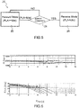
- control system 10 of the gas turbine engine 1 comprises: a control unit 12, configured to perform suitable control algorithms for controlling the engine operation; and a supervising unit 14, operatively coupled to the control unit 12 and configured to supervise its operation.
- control unit 12 comprises: a forward-mode control stage 15, configured to perform suitable control algorithms to control the gas-turbine engine 1 during forward mode operations; and a reverse-mode control stage 16, configured to perform suitable control algorithms to control the gas-turbine engine 1 during reverse mode operations.
- the control system 10 receives measurements of a plurality of engine quantities from sensors (here not shown) coupled to the gas-turbine engine 1, in order to implement the above control algorithms, among which:
- control algorithms implemented by the forward-mode control stage 15 and the reverse-mode control stage 16 are designed to determine a respective driving quantity (e.g. an electric current) for driving the propeller control unit (driving quantity q 1 ), the fuel metering unit of the gas generator 4 in order to determine a corresponding fuel flow W f (driving quantity q 2 ), and the gas generator variable geometry (driving quantity q 3 ); further driving quantities may also be provided by the control unit 12.
- a respective driving quantity e.g. an electric current
- the supervising unit 14 based on an input signal PLA indicative of an input power request, in particular of the angle, or setting, of the pilot's power lever (shown schematically and denoted with 17), is configured to enable either the forward-mode control stage 15 or the reverse-mode control stage 16, in order to activate the forward-mode or the reverse-mode operation of the gas-turbine engine 1.
- the supervising unit 14 comprises a state-transition stage 20, configured to control the state transitions between the forward-mode and the reverse-mode operation of the gas-turbine engine 1, in particular from the forward mode to the reverse mode, when the input signal PLA is indicative of the pilot's request to reverse the engine operation.
- the state-transition stage 20 is configured to determine, at block 22, a pilot's request to transition from forward power (PLA ⁇ idle) to reverse power (PLA ⁇ idle); in other words, the state-transition stage 20, based on the value of the input signal PLA, determines that the pilot has moved the input power lever from the forward position to the reverse position.
- the state-transition stage 20 checks, at block 24, if a safety condition is verified, indicating that a safe transition may be performed (i.e. avoiding the propeller overspeed).
- the state-transition stage 20 checks if the corrected core engine speed N gr is below a given safety threshold Thr: N gr ⁇ Thr .
- the safety threshold Thr may be set according to the operating altitude and according to engine operating parameters, such as the compressor inlet temperature T 2 .
- the safety threshold Thr may be expressed as a scheduled percentage of the core engine speed N gr .
- the state-transition stage 20 maintains the forward-mode operation for the gas-turbine engine 1 (maintaining the forward-mode control stage 15 enabled and disabling the reverse-mode control stage 16).
- the state-transition stage 20 enables, at block 26, the reverse-mode operation for the gas-turbine engine 1 (disabling the forward-mode control stage 15 and enabling the reverse-mode control stage 16).
- the state transition stage 20 therefore represents an enabling stage, configured to enable a transition between the forward and reverse operating modes based on the check that the safety condition is satisfied.
- the safety condition checked by the state-transition stage 20 may include additional parameters; for example, transition to the reverse-mode operation may be enabled only after a so-called WOW (Weight On Wheels) condition is verified, meaning that the aircraft's wheels are on the ground.
- WOW Weight On Wheels
- propeller overspeed (or, in general, any other dangerous condition for the gas turbine engine 1) is automatically and reliably prevented, thanks to the fact that the state transition is enabled only after it is determined that the power delivery of the gas generator 4 due to the inertia is decreased below a threshold.
- Figure 6 shows plots of the propeller speed N p (at different altitude values, as for the plots of Figures 2 and 3 ), after a transition request by the pilot; these plots are the results of simulations performed by the Applicant.
- the present solution allows to automatically control the transition between the forward and reverse operation mode of the gas-turbine engine 1, without the pilot's intervention (and therefore without increasing the pilot's workload, particularly during fast transitions request and complex manoeuvers).
- Occurrence of the propeller overspeed condition is advantageously avoided, thus avoiding the risk of fuel cut-off and engine shut down.
- state-transition stage 20 in the supervising unit 14 of the engine control system 10 may monitor other engine parameters in order to check the safety condition and enable the state transition (in particular from forward to reverse mode), for example the propeller's pitch.
- state-transition stage 20 may advantageously control also the transition from the reverse mode to the forward mode of the engine operation, in addition to the transition from the forward mode to the reverse mode operation, previously discussed in detail.
Description
- The present solution relates to a control system and method for managing a reverse-mode operation in a gas turbine engine, in particular for an aircraft.
- As it is known and as schematically shown in
Figure 1 , agas turbine engine 1, in particular for an aircraft, generally comprises: - an axial/
centrifugal compressor 2, coupled to anair intake 3; - a high-pressure turbine, so called "gas generator" 4, coupled to the axial/
centrifugal compressor 2 via a compressor shaft 5; - a low-pressure turbine, so called "power turbine" 6, driven by, and mechanically decoupled from, the
gas generator 4; and - a propeller 7, coupled to the
power turbine 6 via apower shaft 8 and a suitable gearing 9. - The
gas turbine engine 1 is managed by an automaticelectronic control system 10, that includes an electronic control unit (e.g. a microprocessor, a microcontroller, or similar electronic processing unit) provided with a nonvolatile memory storing suitable software instructions, in order to implement an engine control strategy to meet an input power demand (e.g. originated from a pilot's power lever) . - In particular, it is known that engine operation generally envisages a forward-mode operation, when the pilot's power lever is above an idle position, and a reverse-mode operation, when the pilot's power lever is below an idle position (the idle position representing a zero-angle position for the same lever).
- The present Applicant has realized that known control systems, although generally providing satisfying results, are not able to deal properly with transitions between the forward and reverse operating modes, in particular with transitions from full forward to full reverse operation. A known gas turbine engine control system is defined in
US 4,958,289 . - The aim of the present solution is to provide an improved control of the gas turbine engine, in particular for properly managing a reverse-mode operation thereof.
- According to the present solution, a control system and method are therefore provided, as defined in the appended claims.
- For a better understanding of the present invention, preferred embodiments thereof are now described, purely as non-limiting examples, with reference to the attached drawings, wherein:
-
Figure 1 is a schematic diagram of a gas turbine engine, of a known type; -
Figures 2 and3 show plots related to operation of the gas turbine engine, according to a known control solution; -
Figure 4 is a schematic block diagram of a control system of the gas turbine engine according to the present solution; -
Figure 5 is a schematic block diagram of a control algorithm implemented in the gas turbine engine control system; and -
Figure 6 shows plots related to operation of the gas turbine engine control system ofFigure 4 . - The present solution originates from the Applicant's realization that during manoeuvers such as the so called "aborted take off", when the pilot suddenly demands full reverse from high forward power, or "missed landing after touch down", when the pilot takes off power from full reverse, or in general when the pilot suddenly moves the pilot's lever from a forward position to a reverse position, there is a high risk to bring the engine propeller in a overspeed condition.
- Indeed, when such transitions are commanded, the propeller's pitch crosses the blades flat position (pitch angle ~ 0°), with minimum propeller torque resistance, while the gas generator is still delivering high thermodynamic power because of its inertia.
- In this respect,
Figure 2 shows the plot of the propeller speed Np versus time, when the pilot requests (attime 3,5 s in the exemplary plot) transition from forward to full reverse operation, considering different altitude operating values (the arrow indicating a progressive increase in the altitude level). - The propeller overspeed condition is evident, after the pilot's command, with the propeller speed Np exceeding a target operating value (shown with the dashed line in
Figure 2 , at about 2000 rpm in the example); in particular, the higher is the altitude, the higher is the propeller overspeed amount. - Propeller overspeed may lead to damage and faults, or may eventually result in fuel cut-off or engine shutdown, as a consequence of engine overspeed protection system intervention. Indeed, the engine control system may command a shut down, and shutting down the engine during such operating conditions may lead to high-risk events, such as the aircraft exiting the runway.
- In order to avoid such events, a known solution requires the pilot to take proper actions, while executing the above manoeuvers, in order to avoid the propeller entering the overspeed condition.
- In particular, the pilot is instructed not to move the lever directly from a full-forward to a full-reverse position, but to divide the movement into three phases:
- a first phase, with the lever shifted from full forward to idle;
- a second phase, with the lever maintained at idle; and
- a third phase, with the lever shifted from idle to full reverse.
- Waiting at idle before commanding the reverse operation may allow a reduction of the gas generator power, before the reverse operation is commanded.
- This known solution has, however, a number of drawbacks.
- A high workload is indeed requested from the pilot, who has to consider the propeller speed condition, while performing difficult and risky operations, such as the above mentioned "aborted take off" and "missed landing" operations.
- Moreover, even if the pilot waits at idle before commanding the transition from the forward to the reverse operating mode, the wait time may not be sufficient to avoid propeller overspeed.
- In this regard,
Figure 3 shows different plots of the propeller speed Np (again at different altitude values, as for the plots ofFigure 2 ), considering different lengths of a wait time at the lever's idle position (from 1 to 4 seconds); these plots are the results of simulations performed by the Applicant. - As is clear from these plots, also considering the different possible altitude values, the variable waiting time decided by the pilot in general may not guarantee to avoid the occurrence of propeller overspeed, with a consequent high risk of damage to the gas turbine engine and the aircraft.
- Moreover, the waiting time commanded by the pilot may even be too long, depending on the altitude value and other engine operating conditions, and this could result in a non-proper execution of the desired aircraft manoeuver (such as the above mentioned "aborted take off" and "missed landing" operations).
- An aspect of the present solution therefore envisages reducing the pilot's workload in preventing the propeller overspeed event to occur, by means of an automatic propeller overspeed protection implemented by the engine control system when the pilot requests a transition between the forward and reverse operating modes, e.g. from full forward to full reverse operation. The propeller transition through the flat pitch region is in this case automatically prevented, until a safety condition is verified, indicating that a safe transition may be performed (i.e. avoiding the propeller overspeed).
- In more detail, and with reference to
Figure 4 , thecontrol system 10 of thegas turbine engine 1 comprises: acontrol unit 12, configured to perform suitable control algorithms for controlling the engine operation; and asupervising unit 14, operatively coupled to thecontrol unit 12 and configured to supervise its operation. - In particular, the
control unit 12 comprises: a forward-mode control stage 15, configured to perform suitable control algorithms to control the gas-turbine engine 1 during forward mode operations; and a reverse-mode control stage 16, configured to perform suitable control algorithms to control the gas-turbine engine 1 during reverse mode operations. - The
control system 10 receives measurements of a plurality of engine quantities from sensors (here not shown) coupled to the gas-turbine engine 1, in order to implement the above control algorithms, among which: - gas generator torque Q;
- gas generator (or compressor) variable geometry position Vg;
- core engine speed Ng (i.e. speed of the gas generator 4) ;
- power turbine/propeller speed Np;
- compressor inlet temperature T2;
- compressor inlet pressure δ2; and
- air speed CAS.
- Starting from the core engine speed Ng, the
control system 10 moreover determines a corrected core engine speed Ngr, according to the following expression:

- In a known manner, here not discussed in detail, the control algorithms implemented by the forward-
mode control stage 15 and the reverse-mode control stage 16 are designed to determine a respective driving quantity (e.g. an electric current) for driving the propeller control unit (driving quantity q1), the fuel metering unit of thegas generator 4 in order to determine a corresponding fuel flow Wf (driving quantity q2), and the gas generator variable geometry (driving quantity q3); further driving quantities may also be provided by thecontrol unit 12. - The
supervising unit 14, based on an input signal PLA indicative of an input power request, in particular of the angle, or setting, of the pilot's power lever (shown schematically and denoted with 17), is configured to enable either the forward-mode control stage 15 or the reverse-mode control stage 16, in order to activate the forward-mode or the reverse-mode operation of the gas-turbine engine 1. - According to a particular aspect of the present solution, the
supervising unit 14 comprises a state-transition stage 20, configured to control the state transitions between the forward-mode and the reverse-mode operation of the gas-turbine engine 1, in particular from the forward mode to the reverse mode, when the input signal PLA is indicative of the pilot's request to reverse the engine operation. - In detail, and with reference to
Figure 5 , the state-transition stage 20 is configured to determine, atblock 22, a pilot's request to transition from forward power (PLA ≥ idle) to reverse power (PLA < idle); in other words, the state-transition stage 20, based on the value of the input signal PLA, determines that the pilot has moved the input power lever from the forward position to the reverse position. - After determination of a transition request, the state-
transition stage 20 checks, atblock 24, if a safety condition is verified, indicating that a safe transition may be performed (i.e. avoiding the propeller overspeed). - In this particular embodiment, the state-
transition stage 20 checks if the corrected core engine speed Ngr is below a given safety threshold Thr:
- The safety threshold Thr may be set according to the operating altitude and according to engine operating parameters, such as the compressor inlet temperature T2. For example, the safety threshold Thr may be expressed as a scheduled percentage of the core engine speed Ngr.
- As long as the above safety condition is not satisfied (i.e. as long as Ngr ≥ Thr), the state-
transition stage 20 maintains the forward-mode operation for the gas-turbine engine 1 (maintaining the forward-mode control stage 15 enabled and disabling the reverse-mode control stage 16). - Only after the safety condition is verified (i.e. Ngr < Thr), and with the input power lever still in reverse (PLA < idle), the state-
transition stage 20 enables, atblock 26, the reverse-mode operation for the gas-turbine engine 1 (disabling the forward-mode control stage 15 and enabling the reverse-mode control stage 16). - The
state transition stage 20 therefore represents an enabling stage, configured to enable a transition between the forward and reverse operating modes based on the check that the safety condition is satisfied. - According to a further aspect of the present solution, the safety condition checked by the state-
transition stage 20 may include additional parameters; for example, transition to the reverse-mode operation may be enabled only after a so-called WOW (Weight On Wheels) condition is verified, meaning that the aircraft's wheels are on the ground. - In any case, thanks to the operation of the state-
transition stage 20 in thesupervising unit 14, propeller overspeed (or, in general, any other dangerous condition for the gas turbine engine 1) is automatically and reliably prevented, thanks to the fact that the state transition is enabled only after it is determined that the power delivery of thegas generator 4 due to the inertia is decreased below a threshold. - In this respect,
Figure 6 shows plots of the propeller speed Np (at different altitude values, as for the plots ofFigures 2 and3 ), after a transition request by the pilot; these plots are the results of simulations performed by the Applicant. - As is clear from these plots, even considering different possible altitude values, the occurrence of the propeller overspeed is always avoided (the propeller speed Np does not exceed the target operating value, again shown with a dashed line), when the propeller's pitch crosses the flat position (pitch angle ≈ 0°).
- The advantages of the present solution are clear from the previous discussion.
- In particular, it is again underlined that the present solution allows to automatically control the transition between the forward and reverse operation mode of the gas-
turbine engine 1, without the pilot's intervention (and therefore without increasing the pilot's workload, particularly during fast transitions request and complex manoeuvers). - Occurrence of the propeller overspeed condition is advantageously avoided, thus avoiding the risk of fuel cut-off and engine shut down.
- Finally, it is clear that modifications and variations can be made to what described and illustrated herein, without thereby departing from the scope of the present invention as defined in the appended claims.
- In particular, it is underlined that the state-
transition stage 20 in the supervisingunit 14 of theengine control system 10 may monitor other engine parameters in order to check the safety condition and enable the state transition (in particular from forward to reverse mode), for example the propeller's pitch. - Moreover, it is again underlined that the state-
transition stage 20 may advantageously control also the transition from the reverse mode to the forward mode of the engine operation, in addition to the transition from the forward mode to the reverse mode operation, previously discussed in detail.
Claims (13)
- An electronic control system (10) for a gas turbine engine (1) having a gas generator (4) and a turbine (6) driven by the gas generator (4), comprising:a control unit (12) configured to control a forward operating mode or a reverse operating mode of the gas turbine engine (1); anda supervising unit (14), operatively coupled to the control unit (12), configured to receive an input signal (PLA) indicative of a forward, or reverse, power request and to cause the control unit (12) to control the forward, or reverse, operating mode based on the input signal (PLA),wherein the supervising unit (14) comprises an enabling stage (20) configured to enable a transition between the forward and reverse operating modes based on a check that a safety condition is satisfied,characterized in that the gas-turbine engine (1) comprises a compressor (2) coupled to the gas generator (4), and in that the check on the safety condition is based on a corrected speed (Ngr) of the gas generator (4) , as a function of the altitude and the temperature at the inlet of the compressor (2) .
- The system according to claim 1, wherein the control unit (12) has a first stage (15) configured to control the forward operating mode and a second stage (16) configured to control the reverse operating mode of the gas turbine engine (1), and the supervising unit (14) is configured to enable the first, or second, stage based on the input signal (PLA); wherein the enabling stage (20) is configured to determine, based on the input signal (PLA), a request of transition between the forward to the reverse operating mode, and to disable the first stage (15) and enable the second stage (16) only upon the check on the safety condition being satisfied.
- The system according to claim 1 or 2, wherein the safety condition is related to a residual power of the gas generator (4) due to inertia, upon transition between the forward and the reverse operating modes.
- The control system according to claim 1, wherein the check on the safety condition includes a check if the speed of the gas generator (4) is below a given threshold (Thr) .
- The control system according to claim 4, wherein the threshold (Thr) is a function of the altitude and the temperature at the inlet of the compressor (2).
- The control system according to any of claims 4 and 5, for an aircraft, wherein the safety condition further includes a check if the wheels of the aircraft are on the ground.
- A gas turbine engine (1), comprising the control system (10) according to any of the preceding claims.
- A control method for a gas turbine engine (1), having a gas generator (4) and a turbine (6) driven by the gas generator (4), comprising:activating a forward operating mode or a reverse operating mode based on an input signal (PLA) indicative of a forward, or reverse, power request,further comprising enabling a transition between the forward and reverse operating modes based on a check that a safety condition is satisfied,characterized in that the gas-turbine engine (1) comprises a compressor (2) coupled to the gas generator (4), and in that the check on the safety condition is based on a corrected speed (Ngr) of the gas generator (4), as a function of the altitude and the temperature at the inlet of the compressor (2).
- The control method according to claim 8, wherein enabling comprises determining, based on the input signal (PLA), a request of transition between the forward to the reverse operating mode, and disabling the forward operating mode and enabling the reverse operating mode only upon the check on the safety condition being satisfied.
- The control method according to claim 8 or 9, wherein the safety condition is associated to a residual power of the gas generator (4) due to inertia, upon transition between the forward to the reverse operating modes.
- The control method according to claim 8, wherein the check on the safety condition includes a check if the speed of the gas generator (4) is below a given threshold (Thr) .
- The control method according to claim 11, wherein the threshold (Thr) is a function of the altitude and the temperature at the inlet of the compressor (2).
- The control method according to any of claims 8, 11 and 12, for an aircraft, wherein the safety condition further includes a check if the wheels of the aircraft are on the ground.
Priority Applications (4)
| Application Number | Priority Date | Filing Date | Title |
|---|---|---|---|
| EP17425004.3A EP3351772B1 (en) | 2017-01-20 | 2017-01-20 | Control system and method for managing a reverse-mode operation in a gas turbine engine |
| CN201880007753.1A CN110199103B (en) | 2017-01-20 | 2018-01-19 | Control system and method for managing reverse mode operation in a gas turbine engine |
| US16/479,801 US11649771B2 (en) | 2017-01-20 | 2018-01-19 | Control system and method for managing a reverse-mode operation in a gas turbine engine |
| PCT/EP2018/051364 WO2018134379A1 (en) | 2017-01-20 | 2018-01-19 | Control system and method for managing a reverse-mode operation in a gas turbine engine |
Applications Claiming Priority (1)
| Application Number | Priority Date | Filing Date | Title |
|---|---|---|---|
| EP17425004.3A EP3351772B1 (en) | 2017-01-20 | 2017-01-20 | Control system and method for managing a reverse-mode operation in a gas turbine engine |
Publications (2)
| Publication Number | Publication Date |
|---|---|
| EP3351772A1 EP3351772A1 (en) | 2018-07-25 |
| EP3351772B1 true EP3351772B1 (en) | 2022-05-18 |
Family
ID=58265928
Family Applications (1)
| Application Number | Title | Priority Date | Filing Date |
|---|---|---|---|
| EP17425004.3A Active EP3351772B1 (en) | 2017-01-20 | 2017-01-20 | Control system and method for managing a reverse-mode operation in a gas turbine engine |
Country Status (4)
| Country | Link |
|---|---|
| US (1) | US11649771B2 (en) |
| EP (1) | EP3351772B1 (en) |
| CN (1) | CN110199103B (en) |
| WO (1) | WO2018134379A1 (en) |
Families Citing this family (3)
| Publication number | Priority date | Publication date | Assignee | Title |
|---|---|---|---|---|
| CA2961639A1 (en) | 2014-09-17 | 2016-03-24 | Lonza, Inc. | Activated disinfectant hydrogen peroxide compositions |
| US11414175B2 (en) | 2019-04-01 | 2022-08-16 | Pratt & Whitney Canada Corp. | Method and system for operating an aircraft powerplant |
| US11663863B2 (en) * | 2019-06-07 | 2023-05-30 | Pratt & Whitney Canada Corp. | Methods and systems for operating a rotorcraft |
Family Cites Families (4)
| Publication number | Priority date | Publication date | Assignee | Title |
|---|---|---|---|---|
| US4958289A (en) * | 1988-12-14 | 1990-09-18 | General Electric Company | Aircraft propeller speed control |
| US5416699A (en) | 1992-11-18 | 1995-05-16 | United Technologies Corporation | Propeller speed control having control parameters based on system dynamic characteristics |
| US8651811B2 (en) * | 2005-11-16 | 2014-02-18 | Hamilton Sundstrand | Control logic for a propeller system |
| CA2925870C (en) | 2013-10-11 | 2019-05-14 | Unison Industries, Llc | Method and apparatus for controlling a turboprop engine |
-
2017
- 2017-01-20 EP EP17425004.3A patent/EP3351772B1/en active Active
-
2018
- 2018-01-19 WO PCT/EP2018/051364 patent/WO2018134379A1/en active Application Filing
- 2018-01-19 US US16/479,801 patent/US11649771B2/en active Active
- 2018-01-19 CN CN201880007753.1A patent/CN110199103B/en active Active
Also Published As
| Publication number | Publication date |
|---|---|
| EP3351772A1 (en) | 2018-07-25 |
| US20210215106A1 (en) | 2021-07-15 |
| CN110199103B (en) | 2021-09-03 |
| WO2018134379A1 (en) | 2018-07-26 |
| CN110199103A (en) | 2019-09-03 |
| US11649771B2 (en) | 2023-05-16 |
Similar Documents
| Publication | Publication Date | Title |
|---|---|---|
| EP3205837B1 (en) | Bowed rotor start mitigation in a gas turbine engine using aircraft-derived parameters and corresponding method | |
| US11649771B2 (en) | Control system and method for managing a reverse-mode operation in a gas turbine engine | |
| US8762025B2 (en) | Method and system for controlling a gas turbine and a gas turbine including such a system | |
| EP3073122B1 (en) | Aero gas turbine engine with compressor and associated method | |
| JP5465950B2 (en) | Control device for aircraft gas turbine engine | |
| EP3135883B1 (en) | Propulsion system and method of operating a gas turbine engine of a propulsion system | |
| US20160090918A1 (en) | Method of stopping a rotorcraft engine in overspeed, and a system and a rotorcraft associated therewith | |
| CN111924127A (en) | System and method for detecting a no command or uncontrollable high thrust event in an aircraft | |
| US10150569B2 (en) | Method of stopping a rotorcraft engine in overspeed, and a system and a rotorcraft associated therewith | |
| EP3118437A1 (en) | Gas turbine engine fuel scheduling | |
| EP3738875B1 (en) | Method and system for operating a rotorcraft engine | |
| CN113906204A (en) | Method for regulating the acceleration of a turbomachine | |
| US8800295B2 (en) | Device and a method for regulating a turbine engine, and an aircraft | |
| JP6633962B2 (en) | Aircraft gas turbine engine controller | |
| JP3078822B2 (en) | Acceleration control device for gas turbine engine | |
| US11168621B2 (en) | Method and system for operating an engine in a multi-engine aircraft | |
| US10302021B2 (en) | Detection of uncommanded and uncontrollable high thrust events | |
| EP3855004B1 (en) | Methods and systems for starting a gas turbine engine | |
| RU2482024C2 (en) | Method of helicopter power plant control | |
| US20200284200A1 (en) | Aircraft engine reignition | |
| RU2468229C2 (en) | Monitoring method of gas turbine engine control system | |
| US20240003300A1 (en) | In-flight engine re-start | |
| JP6633963B2 (en) | Aircraft gas turbine engine controller | |
| RU2493392C2 (en) | Method of gas turbine engine | |
| EP4067635A1 (en) | Operating a turboprop engine for in-flight restart |
Legal Events
| Date | Code | Title | Description |
|---|---|---|---|
| PUAI | Public reference made under article 153(3) epc to a published international application that has entered the european phase |
Free format text: ORIGINAL CODE: 0009012 |
|
| STAA | Information on the status of an ep patent application or granted ep patent |
Free format text: STATUS: THE APPLICATION HAS BEEN PUBLISHED |
|
| AK | Designated contracting states |
Kind code of ref document: A1 Designated state(s): AL AT BE BG CH CY CZ DE DK EE ES FI FR GB GR HR HU IE IS IT LI LT LU LV MC MK MT NL NO PL PT RO RS SE SI SK SM TR |
|
| AX | Request for extension of the european patent |
Extension state: BA ME |
|
| STAA | Information on the status of an ep patent application or granted ep patent |
Free format text: STATUS: REQUEST FOR EXAMINATION WAS MADE |
|
| 17P | Request for examination filed |
Effective date: 20190125 |
|
| RBV | Designated contracting states (corrected) |
Designated state(s): AL AT BE BG CH CY CZ DE DK EE ES FI FR GB GR HR HU IE IS IT LI LT LU LV MC MK MT NL NO PL PT RO RS SE SI SK SM TR |
|
| STAA | Information on the status of an ep patent application or granted ep patent |
Free format text: STATUS: REQUEST FOR EXAMINATION WAS MADE |
|
| GRAP | Despatch of communication of intention to grant a patent |
Free format text: ORIGINAL CODE: EPIDOSNIGR1 |
|
| STAA | Information on the status of an ep patent application or granted ep patent |
Free format text: STATUS: GRANT OF PATENT IS INTENDED |
|
| INTG | Intention to grant announced |
Effective date: 20211207 |
|
| GRAS | Grant fee paid |
Free format text: ORIGINAL CODE: EPIDOSNIGR3 |
|
| GRAA | (expected) grant |
Free format text: ORIGINAL CODE: 0009210 |
|
| STAA | Information on the status of an ep patent application or granted ep patent |
Free format text: STATUS: THE PATENT HAS BEEN GRANTED |
|
| AK | Designated contracting states |
Kind code of ref document: B1 Designated state(s): AL AT BE BG CH CY CZ DE DK EE ES FI FR GB GR HR HU IE IS IT LI LT LU LV MC MK MT NL NO PL PT RO RS SE SI SK SM TR |
|
| REG | Reference to a national code |
Ref country code: GB Ref legal event code: FG4D |
|
| REG | Reference to a national code |
Ref country code: CH Ref legal event code: EP |
|
| REG | Reference to a national code |
Ref country code: IE Ref legal event code: FG4D |
|
| REG | Reference to a national code |
Ref country code: DE Ref legal event code: R096 Ref document number: 602017057580 Country of ref document: DE |
|
| REG | Reference to a national code |
Ref country code: AT Ref legal event code: REF Ref document number: 1493273 Country of ref document: AT Kind code of ref document: T Effective date: 20220615 |
|
| REG | Reference to a national code |
Ref country code: LT Ref legal event code: MG9D |
|
| REG | Reference to a national code |
Ref country code: NL Ref legal event code: MP Effective date: 20220518 |
|
| REG | Reference to a national code |
Ref country code: AT Ref legal event code: MK05 Ref document number: 1493273 Country of ref document: AT Kind code of ref document: T Effective date: 20220518 |
|
| PG25 | Lapsed in a contracting state [announced via postgrant information from national office to epo] |
Ref country code: SE Free format text: LAPSE BECAUSE OF FAILURE TO SUBMIT A TRANSLATION OF THE DESCRIPTION OR TO PAY THE FEE WITHIN THE PRESCRIBED TIME-LIMIT Effective date: 20220518 Ref country code: PT Free format text: LAPSE BECAUSE OF FAILURE TO SUBMIT A TRANSLATION OF THE DESCRIPTION OR TO PAY THE FEE WITHIN THE PRESCRIBED TIME-LIMIT Effective date: 20220919 Ref country code: NO Free format text: LAPSE BECAUSE OF FAILURE TO SUBMIT A TRANSLATION OF THE DESCRIPTION OR TO PAY THE FEE WITHIN THE PRESCRIBED TIME-LIMIT Effective date: 20220818 Ref country code: NL Free format text: LAPSE BECAUSE OF FAILURE TO SUBMIT A TRANSLATION OF THE DESCRIPTION OR TO PAY THE FEE WITHIN THE PRESCRIBED TIME-LIMIT Effective date: 20220518 Ref country code: LT Free format text: LAPSE BECAUSE OF FAILURE TO SUBMIT A TRANSLATION OF THE DESCRIPTION OR TO PAY THE FEE WITHIN THE PRESCRIBED TIME-LIMIT Effective date: 20220518 Ref country code: HR Free format text: LAPSE BECAUSE OF FAILURE TO SUBMIT A TRANSLATION OF THE DESCRIPTION OR TO PAY THE FEE WITHIN THE PRESCRIBED TIME-LIMIT Effective date: 20220518 Ref country code: GR Free format text: LAPSE BECAUSE OF FAILURE TO SUBMIT A TRANSLATION OF THE DESCRIPTION OR TO PAY THE FEE WITHIN THE PRESCRIBED TIME-LIMIT Effective date: 20220819 Ref country code: FI Free format text: LAPSE BECAUSE OF FAILURE TO SUBMIT A TRANSLATION OF THE DESCRIPTION OR TO PAY THE FEE WITHIN THE PRESCRIBED TIME-LIMIT Effective date: 20220518 Ref country code: ES Free format text: LAPSE BECAUSE OF FAILURE TO SUBMIT A TRANSLATION OF THE DESCRIPTION OR TO PAY THE FEE WITHIN THE PRESCRIBED TIME-LIMIT Effective date: 20220518 Ref country code: BG Free format text: LAPSE BECAUSE OF FAILURE TO SUBMIT A TRANSLATION OF THE DESCRIPTION OR TO PAY THE FEE WITHIN THE PRESCRIBED TIME-LIMIT Effective date: 20220818 Ref country code: AT Free format text: LAPSE BECAUSE OF FAILURE TO SUBMIT A TRANSLATION OF THE DESCRIPTION OR TO PAY THE FEE WITHIN THE PRESCRIBED TIME-LIMIT Effective date: 20220518 |
|
| PG25 | Lapsed in a contracting state [announced via postgrant information from national office to epo] |
Ref country code: RS Free format text: LAPSE BECAUSE OF FAILURE TO SUBMIT A TRANSLATION OF THE DESCRIPTION OR TO PAY THE FEE WITHIN THE PRESCRIBED TIME-LIMIT Effective date: 20220518 Ref country code: PL Free format text: LAPSE BECAUSE OF FAILURE TO SUBMIT A TRANSLATION OF THE DESCRIPTION OR TO PAY THE FEE WITHIN THE PRESCRIBED TIME-LIMIT Effective date: 20220518 Ref country code: LV Free format text: LAPSE BECAUSE OF FAILURE TO SUBMIT A TRANSLATION OF THE DESCRIPTION OR TO PAY THE FEE WITHIN THE PRESCRIBED TIME-LIMIT Effective date: 20220518 Ref country code: IS Free format text: LAPSE BECAUSE OF FAILURE TO SUBMIT A TRANSLATION OF THE DESCRIPTION OR TO PAY THE FEE WITHIN THE PRESCRIBED TIME-LIMIT Effective date: 20220918 |
|
| PG25 | Lapsed in a contracting state [announced via postgrant information from national office to epo] |
Ref country code: SM Free format text: LAPSE BECAUSE OF FAILURE TO SUBMIT A TRANSLATION OF THE DESCRIPTION OR TO PAY THE FEE WITHIN THE PRESCRIBED TIME-LIMIT Effective date: 20220518 Ref country code: SK Free format text: LAPSE BECAUSE OF FAILURE TO SUBMIT A TRANSLATION OF THE DESCRIPTION OR TO PAY THE FEE WITHIN THE PRESCRIBED TIME-LIMIT Effective date: 20220518 Ref country code: RO Free format text: LAPSE BECAUSE OF FAILURE TO SUBMIT A TRANSLATION OF THE DESCRIPTION OR TO PAY THE FEE WITHIN THE PRESCRIBED TIME-LIMIT Effective date: 20220518 Ref country code: EE Free format text: LAPSE BECAUSE OF FAILURE TO SUBMIT A TRANSLATION OF THE DESCRIPTION OR TO PAY THE FEE WITHIN THE PRESCRIBED TIME-LIMIT Effective date: 20220518 Ref country code: DK Free format text: LAPSE BECAUSE OF FAILURE TO SUBMIT A TRANSLATION OF THE DESCRIPTION OR TO PAY THE FEE WITHIN THE PRESCRIBED TIME-LIMIT Effective date: 20220518 Ref country code: CZ Free format text: LAPSE BECAUSE OF FAILURE TO SUBMIT A TRANSLATION OF THE DESCRIPTION OR TO PAY THE FEE WITHIN THE PRESCRIBED TIME-LIMIT Effective date: 20220518 |
|
| REG | Reference to a national code |
Ref country code: DE Ref legal event code: R097 Ref document number: 602017057580 Country of ref document: DE |
|
| PLBE | No opposition filed within time limit |
Free format text: ORIGINAL CODE: 0009261 |
|
| STAA | Information on the status of an ep patent application or granted ep patent |
Free format text: STATUS: NO OPPOSITION FILED WITHIN TIME LIMIT |
|
| PG25 | Lapsed in a contracting state [announced via postgrant information from national office to epo] |
Ref country code: AL Free format text: LAPSE BECAUSE OF FAILURE TO SUBMIT A TRANSLATION OF THE DESCRIPTION OR TO PAY THE FEE WITHIN THE PRESCRIBED TIME-LIMIT Effective date: 20220518 |
|
| 26N | No opposition filed |
Effective date: 20230221 |
|
| PG25 | Lapsed in a contracting state [announced via postgrant information from national office to epo] |
Ref country code: SI Free format text: LAPSE BECAUSE OF FAILURE TO SUBMIT A TRANSLATION OF THE DESCRIPTION OR TO PAY THE FEE WITHIN THE PRESCRIBED TIME-LIMIT Effective date: 20220518 |
|
| PGFP | Annual fee paid to national office [announced via postgrant information from national office to epo] |
Ref country code: DE Payment date: 20221220 Year of fee payment: 7 |
|
| P01 | Opt-out of the competence of the unified patent court (upc) registered |
Effective date: 20230414 |
|
| REG | Reference to a national code |
Ref country code: CH Ref legal event code: PL |
|
| PG25 | Lapsed in a contracting state [announced via postgrant information from national office to epo] |
Ref country code: LU Free format text: LAPSE BECAUSE OF NON-PAYMENT OF DUE FEES Effective date: 20230120 |
|
| REG | Reference to a national code |
Ref country code: BE Ref legal event code: MM Effective date: 20230131 |
|
| PG25 | Lapsed in a contracting state [announced via postgrant information from national office to epo] |
Ref country code: LI Free format text: LAPSE BECAUSE OF NON-PAYMENT OF DUE FEES Effective date: 20230131 Ref country code: CH Free format text: LAPSE BECAUSE OF NON-PAYMENT OF DUE FEES Effective date: 20230131 |
|
| PG25 | Lapsed in a contracting state [announced via postgrant information from national office to epo] |
Ref country code: BE Free format text: LAPSE BECAUSE OF NON-PAYMENT OF DUE FEES Effective date: 20230131 |
|
| PGFP | Annual fee paid to national office [announced via postgrant information from national office to epo] |
Ref country code: GB Payment date: 20231219 Year of fee payment: 8 |
|
| PG25 | Lapsed in a contracting state [announced via postgrant information from national office to epo] |
Ref country code: IT Free format text: LAPSE BECAUSE OF FAILURE TO SUBMIT A TRANSLATION OF THE DESCRIPTION OR TO PAY THE FEE WITHIN THE PRESCRIBED TIME-LIMIT Effective date: 20220518 Ref country code: IE Free format text: LAPSE BECAUSE OF NON-PAYMENT OF DUE FEES Effective date: 20230120 |
|
| PGFP | Annual fee paid to national office [announced via postgrant information from national office to epo] |
Ref country code: FR Payment date: 20231219 Year of fee payment: 8 |