EP3718786A1 - Brake device for turnable caster - Google Patents
Brake device for turnable caster Download PDFInfo
- Publication number
- EP3718786A1 EP3718786A1 EP19800909.4A EP19800909A EP3718786A1 EP 3718786 A1 EP3718786 A1 EP 3718786A1 EP 19800909 A EP19800909 A EP 19800909A EP 3718786 A1 EP3718786 A1 EP 3718786A1
- Authority
- EP
- European Patent Office
- Prior art keywords
- brake
- wheel
- cable
- brake device
- swivel caster
- Prior art date
- Legal status (The legal status is an assumption and is not a legal conclusion. Google has not performed a legal analysis and makes no representation as to the accuracy of the status listed.)
- Withdrawn
Links
Images


Classifications
-
- B—PERFORMING OPERATIONS; TRANSPORTING
- B60—VEHICLES IN GENERAL
- B60B—VEHICLE WHEELS; CASTORS; AXLES FOR WHEELS OR CASTORS; INCREASING WHEEL ADHESION
- B60B33/00—Castors in general; Anti-clogging castors
- B60B33/0078—Castors in general; Anti-clogging castors characterised by details of the wheel braking mechanism
- B60B33/0081—Castors in general; Anti-clogging castors characterised by details of the wheel braking mechanism acting on tire tread
-
- B—PERFORMING OPERATIONS; TRANSPORTING
- B60—VEHICLES IN GENERAL
- B60B—VEHICLE WHEELS; CASTORS; AXLES FOR WHEELS OR CASTORS; INCREASING WHEEL ADHESION
- B60B33/00—Castors in general; Anti-clogging castors
- B60B33/0078—Castors in general; Anti-clogging castors characterised by details of the wheel braking mechanism
- B60B33/0092—Castors in general; Anti-clogging castors characterised by details of the wheel braking mechanism actuated remotely, e.g. by cable or electrically
-
- B—PERFORMING OPERATIONS; TRANSPORTING
- B62—LAND VEHICLES FOR TRAVELLING OTHERWISE THAN ON RAILS
- B62B—HAND-PROPELLED VEHICLES, e.g. HAND CARTS OR PERAMBULATORS; SLEDGES
- B62B5/00—Accessories or details specially adapted for hand carts
- B62B5/04—Braking mechanisms; Locking devices against movement
- B62B5/0438—Braking mechanisms; Locking devices against movement hand operated
-
- B—PERFORMING OPERATIONS; TRANSPORTING
- B62—LAND VEHICLES FOR TRAVELLING OTHERWISE THAN ON RAILS
- B62B—HAND-PROPELLED VEHICLES, e.g. HAND CARTS OR PERAMBULATORS; SLEDGES
- B62B5/00—Accessories or details specially adapted for hand carts
- B62B5/04—Braking mechanisms; Locking devices against movement
- B62B5/0485—Braking mechanisms; Locking devices against movement by braking on the running surface, e.g. the tyre
-
- B—PERFORMING OPERATIONS; TRANSPORTING
- B60—VEHICLES IN GENERAL
- B60B—VEHICLE WHEELS; CASTORS; AXLES FOR WHEELS OR CASTORS; INCREASING WHEEL ADHESION
- B60B2200/00—Type of product being used or applied
- B60B2200/40—Articles of daily use
- B60B2200/43—Carts
-
- B—PERFORMING OPERATIONS; TRANSPORTING
- B62—LAND VEHICLES FOR TRAVELLING OTHERWISE THAN ON RAILS
- B62B—HAND-PROPELLED VEHICLES, e.g. HAND CARTS OR PERAMBULATORS; SLEDGES
- B62B3/00—Hand carts having more than one axis carrying transport wheels; Steering devices therefor; Equipment therefor
- B62B3/002—Hand carts having more than one axis carrying transport wheels; Steering devices therefor; Equipment therefor characterised by a rectangular shape, involving sidewalls or racks
Definitions
- the present invention relates to a brake device for a swivel caster.
- a brake device for a swivel caster wherein a brake shoe is provided in a frame and an operation member is inserted and fitted in a hole perforated through the top board of the frame, and the operation member is operated synchronously with a brake operation lever through transmitting means configured of a cam, a link rod, or the like, which is connected to the brake operation lever.
- PTL 2 discloses a brake device which uses cables as power transmitting means.
- the brake shoe is operated directly through the cables. This does not complicate the structure if for example the operation lever is in a distant position from the caster, but the cables may be twisted and can sustain damage such as a rupture when repeatedly twisted as the caster repeatedly rotates.
- a brake device for a swivel caster according to the invention has the following features [1] to [5].
- the twisting of the cable is absorbed by the ball chain when the swivel caster rotates. Therefore, the cable is not twisted and can be prevented from suffering damage such as a rupture attributable to such twisting.
- one of the brake shoes acts to come into pressure-contact against (dig into) the peripheral surface of the wheel when the wheel of the caster rotates normally or reversely, so that a sure braking effect can be provided in addition to the above advantageous effect.
- the interposed spring can expand to alleviate the load on the cable and then bias the brake shoe in the releasing direction to carry out the function of releasing the brake in addition to the above advantageous effects.
- cables for multiple operation levers can be connected to the slide member and the cables to brake shoes for multiple casters may be connected to the slide member, so that power from a selected operation lever can be transmitted to a corresponding one of the casters in addition to the above advantageous effects.
- Fig. 1 shows a cage cart 1.
- the cage cart 1 has a rectangular bottom plate 2.
- a fence 3 is provided upright around the bottom plate 2.
- One side of the fence 3 forms a double-opening door 3a.
- Casters 4 are provided at the four corners of the bottom plate 2, two of the casters are swivel casters 4a, and the other two casters are rigid casters 4b.
- the swivel casters 4a each include a substantially U-shaped frame 5 and a wheel 6 rotatably held at the frame, and as shown in Figs. 2 and 3 , a bracket 2a is fixed to the lower surface of the bottom plate 2 with a prescribed gap, a cylindrical shaft 7 is provided through the center of the bracket 2a, and the frame 5 is rotatably provided at the bottom plate 2 of the cart 1 through a bearing 8 mounted to the cylindrical shaft 7.
- the cage cart 1 is provided with a brake device 10 for a swivel caster.
- the brake device 10 includes a brake part 11 provided at the swivel caster 4a, operation members 12 provided at pillars 3b which are in diagonally opposite positions of the fence 3, and power transmitting means 13 which connects the brake part 11 and the operation member 12.
- the brake device 10 for the swivel caster which includes the brake part 11, the operation member 12, and the power transmitting means 13 may be attached as an additional device to a general cage cart which does not have a brake device.
- the brake part 11 is preferably provided for each of the four swivel casters 4a.
- a bracket 14 is provided at each of the side plates 5b of the frame 5 of the swivel caster 4a.
- Two shafts 15 are provided between the brackets 14.
- the shafts 15 are set equidistant from the shaft 6a.
- the brake shoes 16 are rotatably held on the shafts 15.
- the brake shoes 16 are in contact with the circumferential surface of the wheel 6 in one state as shown in Fig. 2 and detached from the circumferential surface of the wheel 6 in the other state as shown in Fig. 3 .
- a rough surface 16a formed by knurling is provided on the peripheral surface of the brake shoe 16, and a hook 16b is formed at the end.
- the shape of the brake shoe 16 is not limited to the illustrated shape and may be a simple plate shape.
- a bracket 17 is provided at the pillar 3b of the fence 3.
- An operation lever 18 is provided pivotably in the bracket 17.
- a tongue piece 18a which holds the cable 22, which will be described, is provided to protrude at the base of the operation lever 18.
- the power transmitting means 13 includes a cable connector 19 provided at a side of the fence 3.
- the cable connector 19 includes a slide member 21 in a case 20.
- the slide member 21 is provided to connect operation member side cables 22 and brake side cables 23.
- the outer tubes 22a of the cables 22 are engaged to one end of the case 20 and the outer tubes 23a of the cables 23 are engaged to the other end of the case 20.
- the inner cables 22b of the cables 22 are engaged to one end of the slide member 21 by screws 21a, and the inner cables 23b are engaged to the other end of the slide member 21 by screws 21b.
- the slide member 21 is biased to the brake side by springs 24 loosely fitted on the inner cables 22b of the cables 22.
- the cables 22 are guided upwardly from the operation member 12 along the pillar 3b and to the cable connector 19 along the upper end and side of the fence 3, and the cables 23 are guided to the base plates 25 of the brake parts 11 provided at the casters along the side of the fence 3.
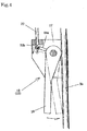
- the opposite end of the cable 22 is engaged to the tongue piece 18a of the operation lever 18 in the operation member 12 as shown in Fig. 4 .
- the base plate 25 is mounted to the bracket 2a fixed at the bottom plate 2 of the cart as shown in Figs. 2 and 3 .
- the base plate 25 has a cable hole 25a formed to extend from the end surface to the center, turn perpendicularly in the center, and reach the lower surface, and a pulley 25b is provided in the turning part.
- the outer tube 23a is engaged to the cable hole 25a of the base plate 25.
- the inner cable 23b inserted through the cable hole 25a is connected to one end of the ball chain 26.
- the ball chain 26 runs over the pulley 25b and through the cylindrical shaft 7 to reach above the brake shoe 16.
- the other end of the ball chain 26 is then connected to two springs 28 through pins 27, and the springs 28 are connected to the hooks 16b of the brake shoes 16.
- the slide member 21 of the cable connector 19 is moved to the brake side by the biasing force of the springs 24 in a normal state, in other words, when the operation lever 18 is in a non-operation position indicated by the solid line.
- the inner cables 23b of the cables 23 are loosened as shown in Fig. 2 , and the brake shoes 16 abut against the circumferential surface of the wheel 6 by their own weights and/or the biasing force of a spring which is not shown.
- the springs 28 expand to alleviate the load on the cables 22b and then provide biasing force to cause the brake shoes 16 to further turn upward, and therefore when the cart 1 is shook lightly and force which causes the wheel 6 to turn is provided, the digging of the brake shoes 16 into the wheel 6 is released and the tensile force of the springs 28 acts to release the brake.
- the cage cart 1 has been illustrated as an example, while the brake device for a swivel caster according to the present invention may be widely used as a brake device for a swivel caster in an item such as a flat cart other than the cage cart described above, a foldable cart, a wheelchair, a stroller, a wagon, a bed, a copier, an IV stand, a compressor, a spot cooler, a generator, and a welding machine.
- the ball chain 26 widely refers to a connector which is not twisted by turning, and the material of the ball chain is not limited.
- the springs 24 and 28 widely refer to machine elements which utilize the elasticity of an object which deforms in response to application of force and returns to the original shape in response to removal of the force, and the coil springs as illustrated as well as a plate spring or a torsion bar may be used.
- the brake device for the swivel caster according to the present invention described above has high durability with a simple power transmission structure, and can therefore be widely used as a brake device for a swivel caster in any of various articles such as a cart and a wheelchair.
Abstract
Description
- The present invention relates to a brake device for a swivel caster.
- As disclosed in
PTL 1, there is a brake device for a swivel caster wherein a brake shoe is provided in a frame and an operation member is inserted and fitted in a hole perforated through the top board of the frame, and the operation member is operated synchronously with a brake operation lever through transmitting means configured of a cam, a link rod, or the like, which is connected to the brake operation lever. -
PTL 2 discloses a brake device which uses cables as power transmitting means. -
- [PTL 1] Japanese Patent Application Publication No.
2008-302903 - [PTL 2] Japanese Patent Application Publication No.
2004-9906 - In the power transmitting means disclosed in
PTL 1, since the cam, the link rod, or the like is necessary to operate the operation member, the structure can be complicated when for example the operation lever is in a distant position from the caster. - Meanwhile, in the power transmitting means disclosed in
PTL 2, the brake shoe is operated directly through the cables. This does not complicate the structure if for example the operation lever is in a distant position from the caster, but the cables may be twisted and can sustain damage such as a rupture when repeatedly twisted as the caster repeatedly rotates. - With the foregoing problem associated with the background art in view, it is an object of the present invention to provide a brake device for a swivel caster having high durability with a simple power transmission structure.
- In order to achieve the above-described object, a brake device for a swivel caster according to the invention has the following features [1] to [5].
- [1] A brake device for a swivel caster, wherein a brake shoe is disposed so as to face a peripheral surface of a wheel of the swivel caster and a cable connected to an operation lever is inserted into a pivot shaft of the caster to be connected to the brake shoe, and wherein a ball chain is interposed at least in a part of the cable inserted into the pivot shaft.
- [2] The brake device for a swivel caster according to [1], wherein two brake shoes are pivotally provided so as to face the peripheral surface of the wheel, and when the brake shoes abut against the peripheral surface of the wheel, one of the brake shoes is provided so as to come into pressure-contact against one rotation direction of the wheel and the other brake shoe is provided so as to come into pressure-contact against the other rotation direction of the wheel.
- [3] The brake device for a swivel caster according to [1] or [2], wherein a part abutting against an outer peripheral surface of the wheel is formed in the brake shoe to have a rough surface.
- [4] The brake device for a swivel caster according to any one of [1] to [3], wherein a spring is interposed in the cable.
- [5] The brake device for a swivel caster according to any one of [1] to [4], wherein a cable connector having a slide member is provided in the middle of the cable, and the cable on an operation lever side is connected to the cable on a brake shoe side through the slide member.
- By the brake device for a swivel caster according to the invention according to [1], the twisting of the cable is absorbed by the ball chain when the swivel caster rotates. Therefore, the cable is not twisted and can be prevented from suffering damage such as a rupture attributable to such twisting.
- By the brake device for a swivel caster according to the invention according to [2], one of the brake shoes acts to come into pressure-contact against (dig into) the peripheral surface of the wheel when the wheel of the caster rotates normally or reversely, so that a sure braking effect can be provided in addition to the above advantageous effect.
- By the brake device for a swivel caster according to the invention according to [3], sufficient friction by the brake shoes against the wheel can be obtained because of the rough surface, so that a more stable and sure braking effect can be provided in addition to the above advantageous effects.
- By the brake device for a swivel caster according to the invention according to [4], when for example the brake shoe digs into the wheel and cannot be easily released, the interposed spring can expand to alleviate the load on the cable and then bias the brake shoe in the releasing direction to carry out the function of releasing the brake in addition to the above advantageous effects.
- By the brake device for a swivel caster according to the invention according to [5], cables for multiple operation levers can be connected to the slide member and the cables to brake shoes for multiple casters may be connected to the slide member, so that power from a selected operation lever can be transmitted to a corresponding one of the casters in addition to the above advantageous effects.
-
-
Fig. 1 is a perspective view illustrating the concept of a cart provided with a brake device for a swivel caster accordance an embodiment of the present invention. -
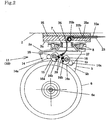
Fig. 2 is a longitudinal sectional view of the caster showing an essential part of the brake device for the swivel caster according to the present invention in a brake activated state. -
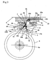
Fig. 3 is a longitudinal sectional view of the caster showing an essential part of a brake device for the swivel caster according to the present invention in a brake released state. -
Fig. 4 is a sectional view illustrating the concept of the operation member of the brake device for the swivel caster according to the present invention. -
Fig. 5 is a sectional view of a cable connector for the brake device for the swivel caster according to the present invention. - Hereinafter, a brake device for a swivel caster according to the present invention will be described in detail with reference to an embodiment shown in the drawings.
-
Fig. 1 shows acage cart 1. Thecage cart 1 has arectangular bottom plate 2. Afence 3 is provided upright around thebottom plate 2. One side of thefence 3 forms a double-openingdoor 3a. -
Casters 4 are provided at the four corners of thebottom plate 2, two of the casters areswivel casters 4a, and the other two casters arerigid casters 4b. Theswivel casters 4a each include a substantiallyU-shaped frame 5 and awheel 6 rotatably held at the frame, and as shown inFigs. 2 and3 , abracket 2a is fixed to the lower surface of thebottom plate 2 with a prescribed gap, acylindrical shaft 7 is provided through the center of thebracket 2a, and theframe 5 is rotatably provided at thebottom plate 2 of thecart 1 through abearing 8 mounted to thecylindrical shaft 7. - The
cage cart 1 is provided with abrake device 10 for a swivel caster. Thebrake device 10 includes abrake part 11 provided at theswivel caster 4a,operation members 12 provided atpillars 3b which are in diagonally opposite positions of thefence 3, andpower transmitting means 13 which connects thebrake part 11 and theoperation member 12. Thebrake device 10 for the swivel caster which includes thebrake part 11, theoperation member 12, and the power transmitting means 13 may be attached as an additional device to a general cage cart which does not have a brake device. When all of thecasters 4 provided at the four corners of the cart areswivel casters 4a, thebrake part 11 is preferably provided for each of the fourswivel casters 4a. - In the
brake part 11 as shown inFigs. 2 and3 , abracket 14 is provided at each of theside plates 5b of theframe 5 of theswivel caster 4a. Twoshafts 15 are provided between thebrackets 14. Theshafts 15 are set equidistant from theshaft 6a. Thebrake shoes 16 are rotatably held on theshafts 15. Thebrake shoes 16 are in contact with the circumferential surface of thewheel 6 in one state as shown inFig. 2 and detached from the circumferential surface of thewheel 6 in the other state as shown inFig. 3 . Arough surface 16a formed by knurling is provided on the peripheral surface of thebrake shoe 16, and ahook 16b is formed at the end. The shape of thebrake shoe 16 is not limited to the illustrated shape and may be a simple plate shape. - As shown in
Fig. 4 , in theoperation member 12, abracket 17 is provided at thepillar 3b of thefence 3. Anoperation lever 18 is provided pivotably in thebracket 17. Atongue piece 18a which holds thecable 22, which will be described, is provided to protrude at the base of theoperation lever 18. - The power transmitting means 13 includes a
cable connector 19 provided at a side of thefence 3. As shown inFig. 5 , thecable connector 19 includes aslide member 21 in acase 20. Theslide member 21 is provided to connect operationmember side cables 22 andbrake side cables 23. In thecable connector 19, theouter tubes 22a of thecables 22 are engaged to one end of thecase 20 and theouter tubes 23a of thecables 23 are engaged to the other end of thecase 20. Theinner cables 22b of thecables 22 are engaged to one end of theslide member 21 byscrews 21a, and theinner cables 23b are engaged to the other end of theslide member 21 byscrews 21b. In thecable connector 19, theslide member 21 is biased to the brake side bysprings 24 loosely fitted on theinner cables 22b of thecables 22. As shown inFig. 1 , thecables 22 are guided upwardly from theoperation member 12 along thepillar 3b and to thecable connector 19 along the upper end and side of thefence 3, and thecables 23 are guided to thebase plates 25 of thebrake parts 11 provided at the casters along the side of thefence 3. - The opposite end of the
cable 22 is engaged to thetongue piece 18a of theoperation lever 18 in theoperation member 12 as shown inFig. 4 . Meanwhile, thebase plate 25 is mounted to thebracket 2a fixed at thebottom plate 2 of the cart as shown inFigs. 2 and3 . Thebase plate 25 has acable hole 25a formed to extend from the end surface to the center, turn perpendicularly in the center, and reach the lower surface, and apulley 25b is provided in the turning part. At the opposite end of thecable 23, theouter tube 23a is engaged to thecable hole 25a of thebase plate 25. Theinner cable 23b inserted through thecable hole 25a is connected to one end of theball chain 26. Theball chain 26 runs over thepulley 25b and through thecylindrical shaft 7 to reach above thebrake shoe 16. The other end of theball chain 26 is then connected to twosprings 28 throughpins 27, and thesprings 28 are connected to thehooks 16b of thebrake shoes 16. - By the
brake device 10 for the swivel caster according to the embodiment, theslide member 21 of thecable connector 19 is moved to the brake side by the biasing force of thesprings 24 in a normal state, in other words, when theoperation lever 18 is in a non-operation position indicated by the solid line. In this way, theinner cables 23b of thecables 23 are loosened as shown inFig. 2 , and thebrake shoes 16 abut against the circumferential surface of thewheel 6 by their own weights and/or the biasing force of a spring which is not shown. - In this state, when the
wheel 6 is rotated for example in the clockwise direction, theright brake shoe 16 is rotated in the counterclockwise direction as thewheel 6 is rotated, and acts to come into pressure-contact against the circumferential surface of the wheel 6 (when thewheel 6 is made of rubber, the pressure contacting force causes theright brake shoe 16 to dig into the rubber wheel 6). Therefore, the clockwise rotation of thewheel 6 is locked. Conversely, when thewheel 6 is rotated in the counterclockwise direction, theleft brake shoe 16 is rotated in the clockwise direction as thewheel 6 is rotated, and acts to come into pressure-contact against the circumferential surface of the wheel 6 (when thewheel 6 is made of rubber, the pressure contacting force causes theleft brake shoe 16 to dig into the rubber wheel 6). The counterclockwise rotation of thewheel 6 is therefore locked. - When the
operation lever 18 is operated in the direction of thepillar 3b (to the position indicated by the double-dotted chain line), theinner cable 22b of thecable 22 is pulled up, which causes theslide member 21 of thecable connector 19 to be pulled toward the operation member. Thebrake shoes 16 are then caused to turn upward through theball chain 26 and thesprings 28, and thebrake shoes 16 are detached from the circumferential surface of thewheel 6. This allows thewheel 6 to rotate freely and thecart 1 to travel in a desired direction. At the time, thebrake shoes 16 are prevented from further turning bystoppers 14a provided in thebracket 14. When for example thebrake shoes 16 dig into thewheel 6 and cannot be easily moved to turn upward, thesprings 28 expand to alleviate the load on thecables 22b and then provide biasing force to cause thebrake shoes 16 to further turn upward, and therefore when thecart 1 is shook lightly and force which causes thewheel 6 to turn is provided, the digging of thebrake shoes 16 into thewheel 6 is released and the tensile force of thesprings 28 acts to release the brake. - While the brake device for the swivel caster according to the embodiment of the present invention has been described, it should be understood that the described embodiment is not intended to limit the invention, and various modifications and changes may be made within the scope of the technical ideas of the present invention as set forth in the appended claims.
- For example in the description of the embodiment, the
cage cart 1 has been illustrated as an example, while the brake device for a swivel caster according to the present invention may be widely used as a brake device for a swivel caster in an item such as a flat cart other than the cage cart described above, a foldable cart, a wheelchair, a stroller, a wagon, a bed, a copier, an IV stand, a compressor, a spot cooler, a generator, and a welding machine. According to the present invention, theball chain 26 widely refers to a connector which is not twisted by turning, and the material of the ball chain is not limited. According to the present invention, thesprings - The brake device for the swivel caster according to the present invention described above has high durability with a simple power transmission structure, and can therefore be widely used as a brake device for a swivel caster in any of various articles such as a cart and a wheelchair.
-
- 1
- Cart
- 2
- Bottom plate
- 3
- Fence
- 3a
- Door
- 3b
- Pillar
- 4
- Caster
- 4a
- Swivel caster
- 4b
- Rigid caster
- 5
- Frame
- 5a
- Top plate
- 6
- Wheel
- 6a
- Shaft
- 7
- Cylindrical shaft
- 8
- Bearing
- 10
- Brake device
- 11
- Brake part
- 12
- Operation member
- 13
- Power transmitting means
- 14
- Bracket
- 14a
- Stopper
- 15
- Shaft
- 16
- Brake shoe
- 16a
- Rough surface
- 20
- Case
- 21
- Slide member
- 21a, 21b
- Screw
- 22
- Operation member side cable
- 22a
- Outer tube
- 22b
- Inner cable
- 23
- Brake side cable
- 23a
- Outer tube
- 23b
- Inner cable
- 24
- Spring
- 25
- Base plate
- 26
- Ball chain
- 27
- Pin
- 28
- Spring
Claims (5)
- A brake device for a swivel caster, wherein a brake shoe is disposed so as to face a peripheral surface of a wheel of the swivel caster and a cable connected to an operation lever is inserted into a pivot shaft of the caster to be connected to the brake shoe, and wherein
a ball chain is interposed at least in a part of the cable inserted into the pivot shaft. - The brake device for a swivel caster according to claim 1, wherein
two brake shoes are pivotally provided so as to face the peripheral surface of the wheel, and when the brake shoes abut against the peripheral surface of the wheel, one of the brake shoes is provided so as to come into pressure-contact against one rotation direction of the wheel and the other brake shoe is provided so as to come into pressure-contact against the other rotation direction of the wheel. - The brake device for a swivel caster according to claim 1 or 2, wherein
a part abutting against an outer peripheral surface of the wheel is formed in the brake shoe to have a rough surface. - The brake device for a swivel caster according to any one of claims 1 to 3, wherein
a spring is interposed in the cable. - The brake device for a swivel caster according to any one of claims 1 to 4, wherein
a cable connector having a slide member is provided in the middle of the cable, and
the cable on an operation lever side is connected to the cable on a brake shoe side through the slide member.
Applications Claiming Priority (3)
| Application Number | Priority Date | Filing Date | Title |
|---|---|---|---|
| JP2018141999 | 2018-07-30 | ||
| JP2018146075A JP2020023200A (en) | 2018-07-30 | 2018-08-02 | Brake control system of revolvable caster |
| PCT/JP2019/012127 WO2020026517A1 (en) | 2018-07-30 | 2019-03-22 | Brake device for turnable caster |
Publications (2)
| Publication Number | Publication Date |
|---|---|
| EP3718786A1 true EP3718786A1 (en) | 2020-10-07 |
| EP3718786A4 EP3718786A4 (en) | 2021-08-04 |
Family
ID=69618102
Family Applications (1)
| Application Number | Title | Priority Date | Filing Date |
|---|---|---|---|
| EP19800909.4A Withdrawn EP3718786A4 (en) | 2018-07-30 | 2019-03-22 | Brake device for turnable caster |
Country Status (4)
| Country | Link |
|---|---|
| US (1) | US20210001666A1 (en) |
| EP (1) | EP3718786A4 (en) |
| JP (1) | JP2020023200A (en) |
| CN (1) | CN110997348A (en) |
Families Citing this family (2)
| Publication number | Priority date | Publication date | Assignee | Title |
|---|---|---|---|---|
| JP7431010B2 (en) * | 2019-10-16 | 2024-02-14 | 株式会社ジェネシス | caster brake device |
| JP7454839B2 (en) | 2020-03-27 | 2024-03-25 | 株式会社アルミス | caster |
Family Cites Families (13)
| Publication number | Priority date | Publication date | Assignee | Title |
|---|---|---|---|---|
| CH556757A (en) * | 1971-11-23 | 1974-12-13 | Trioteam As | DEVICE FOR LOCKING SWIVEL CASTORS ON MACHINERY OR FURNITURE. |
| US4248445A (en) * | 1979-06-18 | 1981-02-03 | Vassar Hervey P | Caster brake and swivel lock |
| JP3683952B2 (en) * | 1995-10-23 | 2005-08-17 | オーエム機器株式会社 | Casters with turning control and braking mechanism |
| JPH1148704A (en) * | 1997-08-08 | 1999-02-23 | Futaba Kinzoku Kogyo Kk | Caster having brake mechanism |
| JP3844450B2 (en) * | 2002-06-07 | 2006-11-15 | 三甲株式会社 | Transport cart |
| JP4236534B2 (en) * | 2003-07-29 | 2009-03-11 | 亀井 慎一郎 | Casters |
| JP5108336B2 (en) * | 2006-07-06 | 2012-12-26 | 株式会社内外 | Caster braking device |
| JP2008179312A (en) * | 2007-01-26 | 2008-08-07 | Masayasu Naga | Caster and chair using the same |
| JP5506794B2 (en) * | 2010-02-25 | 2014-05-28 | 株式会社日乃本錠前 | Caster with hand brake |
| JP5719869B2 (en) * | 2013-04-22 | 2015-05-20 | 株式会社日乃本錠前 | Caster with brake |
| JP5716120B1 (en) * | 2014-02-05 | 2015-05-13 | 株式会社日乃本錠前 | Caster with hand brake |
| US9908367B2 (en) * | 2014-02-07 | 2018-03-06 | Nansin Co., Ltd. | Double-lock caster |
| JP5848401B2 (en) * | 2014-06-10 | 2016-01-27 | 株式会社日乃本錠前 | Caster with stopper |
-
2018
- 2018-08-02 JP JP2018146075A patent/JP2020023200A/en active Pending
-
2019
- 2019-03-22 US US16/610,959 patent/US20210001666A1/en not_active Abandoned
- 2019-03-22 EP EP19800909.4A patent/EP3718786A4/en not_active Withdrawn
- 2019-03-22 CN CN201980002879.4A patent/CN110997348A/en active Pending
Also Published As
| Publication number | Publication date |
|---|---|
| EP3718786A4 (en) | 2021-08-04 |
| JP2020023200A (en) | 2020-02-13 |
| CN110997348A (en) | 2020-04-10 |
| US20210001666A1 (en) | 2021-01-07 |
Similar Documents
| Publication | Publication Date | Title |
|---|---|---|
| JP4407428B2 (en) | Locking device | |
| EP3718786A1 (en) | Brake device for turnable caster | |
| CN101451574B (en) | Rolling brake structure | |
| US8955912B2 (en) | Seat assembly having a foldable seat back | |
| EP0893615A2 (en) | Disk brake device | |
| US10589584B2 (en) | Fail-safe latch mechanism | |
| US5494386A (en) | Apparatus for retaining a load in a vehicle | |
| US6814691B1 (en) | Secured mount for a body inversion exerciser | |
| EP3044042B1 (en) | Retractor with gimbaled vehicle sensor | |
| US5622408A (en) | Seat reclining apparatus for a vehicle | |
| CN101408220B (en) | Rotary brake structure and component | |
| US7011330B2 (en) | Automatic hitch assembly | |
| JP2013119366A (en) | Lift axle device | |
| JP2016060216A (en) | Ottoman | |
| US3335619A (en) | Steering wheel shaft column | |
| WO2020026517A1 (en) | Brake device for turnable caster | |
| KR101395447B1 (en) | A display apparatus | |
| US20150139746A1 (en) | Latch Assembly | |
| JP5766558B2 (en) | Braking device for universal wheel in handcart | |
| JP2017125338A (en) | Boom drop prevention device | |
| JP2006188091A (en) | Accelerator pedal structure | |
| WO2013157491A1 (en) | Caster | |
| US10569832B2 (en) | Drive for a wheeled vehicle, particularly a bicycle | |
| KR20130068094A (en) | Brake pedal for preventing reverse rotation | |
| EP3636464A1 (en) | Lifting device for a vehicle axle |
Legal Events
| Date | Code | Title | Description |
|---|---|---|---|
| STAA | Information on the status of an ep patent application or granted ep patent |
Free format text: STATUS: UNKNOWN |
|
| STAA | Information on the status of an ep patent application or granted ep patent |
Free format text: STATUS: THE INTERNATIONAL PUBLICATION HAS BEEN MADE |
|
| PUAI | Public reference made under article 153(3) epc to a published international application that has entered the european phase |
Free format text: ORIGINAL CODE: 0009012 |
|
| STAA | Information on the status of an ep patent application or granted ep patent |
Free format text: STATUS: REQUEST FOR EXAMINATION WAS MADE |
|
| 17P | Request for examination filed |
Effective date: 20200630 |
|
| AK | Designated contracting states |
Kind code of ref document: A1 Designated state(s): AL AT BE BG CH CY CZ DE DK EE ES FI FR GB GR HR HU IE IS IT LI LT LU LV MC MK MT NL NO PL PT RO RS SE SI SK SM TR |
|
| AX | Request for extension of the european patent |
Extension state: BA ME |
|
| A4 | Supplementary search report drawn up and despatched |
Effective date: 20210702 |
|
| RIC1 | Information provided on ipc code assigned before grant |
Ipc: B60B 33/00 20060101AFI20210628BHEP Ipc: B62B 5/04 20060101ALI20210628BHEP Ipc: B62B 3/00 20060101ALI20210628BHEP |
|
| DAV | Request for validation of the european patent (deleted) | ||
| DAX | Request for extension of the european patent (deleted) | ||
| STAA | Information on the status of an ep patent application or granted ep patent |
Free format text: STATUS: THE APPLICATION IS DEEMED TO BE WITHDRAWN |
|
| 18D | Application deemed to be withdrawn |
Effective date: 20220201 |