EP3718648B1 - Optical sorter - Google Patents
Optical sorter Download PDFInfo
- Publication number
- EP3718648B1 EP3718648B1 EP18905564.3A EP18905564A EP3718648B1 EP 3718648 B1 EP3718648 B1 EP 3718648B1 EP 18905564 A EP18905564 A EP 18905564A EP 3718648 B1 EP3718648 B1 EP 3718648B1
- Authority
- EP
- European Patent Office
- Prior art keywords
- sidewalls
- frame
- optical
- chute
- optical sorter
- Prior art date
- Legal status (The legal status is an assumption and is not a legal conclusion. Google has not performed a legal analysis and makes no representation as to the accuracy of the status listed.)
- Active
Links
Images



Classifications
-
- B—PERFORMING OPERATIONS; TRANSPORTING
- B07—SEPARATING SOLIDS FROM SOLIDS; SORTING
- B07C—POSTAL SORTING; SORTING INDIVIDUAL ARTICLES, OR BULK MATERIAL FIT TO BE SORTED PIECE-MEAL, e.g. BY PICKING
- B07C5/00—Sorting according to a characteristic or feature of the articles or material being sorted, e.g. by control effected by devices which detect or measure such characteristic or feature; Sorting by manually actuated devices, e.g. switches
- B07C5/34—Sorting according to other particular properties
- B07C5/342—Sorting according to other particular properties according to optical properties, e.g. colour
-
- B—PERFORMING OPERATIONS; TRANSPORTING
- B07—SEPARATING SOLIDS FROM SOLIDS; SORTING
- B07C—POSTAL SORTING; SORTING INDIVIDUAL ARTICLES, OR BULK MATERIAL FIT TO BE SORTED PIECE-MEAL, e.g. BY PICKING
- B07C5/00—Sorting according to a characteristic or feature of the articles or material being sorted, e.g. by control effected by devices which detect or measure such characteristic or feature; Sorting by manually actuated devices, e.g. switches
- B07C5/34—Sorting according to other particular properties
- B07C5/342—Sorting according to other particular properties according to optical properties, e.g. colour
- B07C5/3425—Sorting according to other particular properties according to optical properties, e.g. colour of granular material, e.g. ore particles, grain
-
- B—PERFORMING OPERATIONS; TRANSPORTING
- B07—SEPARATING SOLIDS FROM SOLIDS; SORTING
- B07C—POSTAL SORTING; SORTING INDIVIDUAL ARTICLES, OR BULK MATERIAL FIT TO BE SORTED PIECE-MEAL, e.g. BY PICKING
- B07C2501/00—Sorting according to a characteristic or feature of the articles or material to be sorted
- B07C2501/0018—Sorting the articles during free fall
-
- B—PERFORMING OPERATIONS; TRANSPORTING
- B07—SEPARATING SOLIDS FROM SOLIDS; SORTING
- B07C—POSTAL SORTING; SORTING INDIVIDUAL ARTICLES, OR BULK MATERIAL FIT TO BE SORTED PIECE-MEAL, e.g. BY PICKING
- B07C5/00—Sorting according to a characteristic or feature of the articles or material being sorted, e.g. by control effected by devices which detect or measure such characteristic or feature; Sorting by manually actuated devices, e.g. switches
- B07C5/36—Sorting apparatus characterised by the means used for distribution
- B07C5/363—Sorting apparatus characterised by the means used for distribution by means of air
- B07C5/365—Sorting apparatus characterised by the means used for distribution by means of air using a single separation means
- B07C5/366—Sorting apparatus characterised by the means used for distribution by means of air using a single separation means during free fall of the articles
Definitions
- the present invention relates to an optical sorter which sorts out granular objects such as grains and resin pellets on the basis of colors and/or the like, and specifically relates to an optical sorter which enables to attain positional accuracy of component members attached to a frame.
- An optical sorter disclosed in each of JP 5218374 B2 and JP 5605172 B2 comprises a granular object feed part, an inclined chute, an optical sorting part and a discharge hopper.
- granular objects which are a raw material are fed from the granular object feed part, then flow down on the surface of the inclined chute, drop from the lower end thereof, after that, are detected at the optical sorting part, are determined to be good or defective based on colors and/or the like, are sorted out into good articles and defective articles by excluding the defective articles, and then, are discharged separately as the good articles and the defective articles from the discharge hopper.
- each optical sorter above also employs a structure of attaching to the frame, component members including the granular object feed part, the inclined chute, the optical sorting part and the discharge hopper, it is difficult to attain high positional accuracy of the component members when welding distortion occurs on the frame, which difficulty problematically largely affects sorting accuracy.
- GB 676989 A discloses a further photo-electrical sorting machine having diagonally shaped coupling braces fixed to the frame of an optical sorting machine.
- an object of the present invention is to provide an optical sorter which enables to eliminate occurrence of welding distortion on a frame and simply attain high positional accuracy of component members attached to the frame.
- the object of the invention is solved by an optical sorter according to claim 1.
- an optical sorter comprising:
- the braces preferably couple the sidewalls on the front side of the sidewalls and the rear side of the sidewalls in a diagonal shape.
- the chute is preferably attached to the frame on the front side of the sidewalls, and the braces preferably couple the sidewalls of the frame on the rear side of the chute.
- the frame preferably comprises an electric equipment base arranged between the sidewalls and screw-fixed to the sidewalls, and the optical detection means and the ejector means are preferably arranged on the electric equipment base.
- the frame preferably further comprises a top board, a feeder base and a dust collection duct arranged between the sidewalls and screw-fixed to the sidewalls, and a raw material tank is preferably placed and fixed onto the top board, a vibrating feeder that feeds granular objects stored in the raw material tank to the chute is preferably placed and fixed onto the feeder base, and the discharge hopper is preferably arranged on a front face of the dust collection duct in a state of being screw-fixed onto the base.
- one or more of sorting units each including the chute, the optical detection means, the ejector means and the discharge hopper are preferably provided between the sidewalls of the frame.
- the optical sorter according to the present invention employs a structure of screw-fixing the pair of sidewalls in the right-left direction onto the base to assemble the frame, thereby can eliminate occurrence of welding distortion on the frame, can secure rigidity of the frame by diagonally coupling the sidewalls of the frame with the braces, and can attain high positional accuracy of the chute, the optical detection means, the ejector means and the discharge hopper which are the component members attached to the frame through adjustments of the lengths of the braces.
- the optical sorter according to the present invention employs a structure of assembling the frame by screw-fixing in place of conventional welding, and thereby can simplify assembly steps.
- the optical sorter according to the present invention can accurately attain high positional accuracy of the component members attached to the frame, and can improve rigidity of the frame.
- the optical sorter can arrange the braces effectively using a space rearward of the chute.
- the optical sorter can improve rigidity of the frame by fixing the electric equipment base to the sidewalls, and facilitates attachments of the optical detection means and the ejector means to the frame.
- the optical sorter can further improve the rigidity of the frame by fixing top board, the feeder base and the dust collection duct to the sidewalls, and facilitates attachments of the raw material tank, the vibrating feeder and the discharge hopper to the frame.
- the optical sorter according to the present invention can be used as a single optical sorter or an optical sorter having functions to be obtained by providing a plurality of single optical sorters.
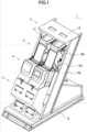
- FIG. 1 shows a perspective view an optical sorter according to an embodiment of the present invention.
- FIG. 2 shows a front view of the optical sorter in FIG. 1 .
- FIG. 3 shows a rear view of the optical sorter in FIG. 1 .
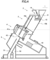
- FIG. 4 shows a schematic lateral sectional view of the optical sorter in FIG. 1 .
- an optical sorter 1 comprises two sets of sorting units arranged side by side, each unit including a granular object feed part 2, a chute 3, an optical sorting part 4 and a discharge hopper 5.
- the sorting units have substantially the same configurations, and the description is herein made based on one set of sorting unit.
- the optical sorter 1 comprises: the granular object feed part 2 for feeding granular objects which are a raw material; the chutes 3 arranged to slope and to allow the granular objects to flow down; the optical sorting parts 4 for detecting the granular objects dropping from the lower ends of the chutes 3 and sorting out good articles from defective articles on the basis of the detection result; and the discharge hopper 5 for separating and discharging the granular objects sorted out by the optical sorting parts 4 into the good articles and the defective articles.
- the granular object feed part 2 includes a raw material tank (not shown), and vibrating feeders 21 which feed the granular objects stored in the raw material tank to the chutes 3.
- the chute 3 has a predetermined width and is arranged at a position below the distal end of the vibrating feeder 21 in the state of sloping, and allows the granular objects fed from the vibrating feeder 21 to freely flow down.
- the optical sorting part 4 includes: a pair of optical detection devices 41a and 41b arranged on the front and rear sides of dropping trajectories of the granular objects dropping from the lower end of the chute 3; a determination device 42 which determines whether the granular objects are good articles or defective articles on the basis of image capturing signals of the optical detection devices 41a and 41b; and an ejector device which excludes the defective articles on the basis of the determination result of the determination device 42 thereby to sort out the granular objects into the good articles and the defective articles.
- the discharge hopper 5 has a good article discharge path 51 and a defective article discharge path 52, and separates and discharges the granular objects sorted out by the ejector device into the good articles and the defective articles.
- discharge hopper 5 is provided an integrated discharge hopper for the two sets of units arranged side by side herein, it is not necessarily required to have an integrated one but may have separate ones.
- the granular objects stored in the raw material tank of the granular object feed part 2 are continuously fed to the chute 3 with the vibrating feeder 21, freely flow down in the state of spreading in the width direction on the surface of the chute 3, and after that, freely fall along predetermined trajectories from the lower end of the chute 3.
- Images of the granular objects dropping from the lower end of the chute 3 are captured by image capturing means of the pair of optical detection devices 41a and 41b in the optical sorting part 4, and the determination device 42 determines whether the granular objects are good articles or defective articles by comparing, with thresholds, signal levels of a quantity of light and color components in an image capturing signal from the image capturing means, and the granular objects are sorted out into the good articles and the defective articles by the defective articles excluded from the predetermined trajectories with ejection of air by the ejector device on the basis of an exclusion signal sent from the determination device 42.
- the granular objects that are sorted out as the good articles are discharged from the good article discharge path 51 of the discharge hopper 5, and the granular objects that are sorted out as the defective articles are discharged from the defective article discharge path 52 of the discharge hopper 5, respectively.
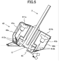
- FIG. 5 shows an explanatory diagram of the optical detection devices.
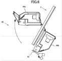
- FIG. 6 shows an explanatory diagram of the optical detection devices in FIG. 5 in the state where the front optical detection device is caused to pivot upward.
- the optical detection devices 41a and 41b include: image capturing means 411a, 411b, such as CCD cameras, which have built-in line sensors and/or area sensors, such as CCDs, which are able to handle granular objects freely falling in the state of spreading in the width direction from the lower end of the chute 3 and are able to receive light in a wavelength band of near infrared rays (NIR), visible light, ultraviolet rays or the like; lighting means 412a, 412b, such as fluorescent lamps, halogen lamps and LED light sources, which illuminate a detection position O on the dropping trajectories of the granular objects; and backgrounds which are backgrounds in capturing images of the granular objects at the detection position O with the image capturing means 411a, 411b.
- image capturing means 411a, 411b such as CCD cameras, which have built-in line sensors and/or area sensors, such as CCDs, which are able to handle granular objects freely falling in the state of spreading in the width direction from the
- the pair of optical detection devices 41a and 41b constitute a camera unit 45 by being arranged in a pair of front and rear covers 44a and 44b which are coupled so as to be able to be opened and closed at their top portions with a hinge.
- the ejector device includes an ejector nozzle 43 which can, similarly to the optical detection devices 41a and 41b, handle granular objects freely falling in the state of spreading in the width direction from the lower end of the chute 3 and which can eject air selectively from a plurality of nozzle holes formed in the width direction; and an ejector drive device (not shown) which causes the ejector nozzle 43 to eject air on the basis of the exclusion signal sent from the determination device 42.
- the ejector nozzle 43 may be integrally attached to the camera unit 45.
- FIG. 7 shows an exploded perspective view of the optical sorter in FIG. 1 .
- the optical sorter 1 includes: a base 12; a pair of right and left sidewalls 13a and 13b which are stood and screw-fixed onto the base 12; and a frame 11 having a top board 14, a feeder base 15, an electric equipment base 16 and a dust collection duct 17, each transversely provided between the sidewalls 13a and 13b and screw-fixed to the sidewalls 13a and 13b.
- the sidewalls 13a and 13b are coupled with pairs of braces 18a and 18b in a diagonal shape on the front side of the sidewalls 13a and 13b and the rear side of the sidewalls 13a and 13b.
- the braces 18a and 18b herein are known, each brace having two steel rods coupled with a turnbuckle.
- a coupling plate member is fixed to one end of the steel rod by welding or the like, and the coupling plate members are coupled to the front faces or the rear faces of the sidewall 13a, 13b with bolts or the like, and the braces 18a and 18b can be adjusted in terms of their lengths by rotating the turnbuckles to put the steel rods forward or backward.
- the raw material tank (not shown) is placed and screw-fixed onto the top board 14 of the frame 11, and the vibrating feeders 21 are placed and screw-fixed onto the feeder base 15.
- the determination devices 42 and electric equipment units including the ejector drive device and the like are arranged as well as the camera units 45 and the ejector nozzles 43, and on the front face of the dust collection duct 17, the discharge hopper 5 is arranged in the state of being screw-fixed to the base 12.
- the camera unit 45 is arranged on the electric equipment base 16 of the frame 11 in the state of sandwiching the chute 3 in the pair of the front and rear covers 44a and 44b and between the pair of optical detection devices 41a and 41b.
- the chute 3 is attached to the frame 11 on the front side of the sidewalls 13a and 13b, and the braces 18a and 18b are arranged in a space formed on the rear side of the chute 3.
- the optical sorter 1 employs a structure in which the pair of right and left sidewalls 13a and 13b are stood and screw-fixed onto the base 12, and the top board 14, the feeder base 15, the electric equipment base 16 and the dust collection duct 17 are transversely provided between the sidewalls 13a and 13b and screw-fixed to the sidewalls 13a and 13b to assemble the frame 11, welding distortion does not occur on the frame 11.
- the sidewalls 13a and 13b of the frame 11 are coupled with the diagonal braces 18a and 18b crossing each other on the front and rear sides of the sidewalls 13a and 13b, rigidity of the frame 11 can be secured, and adjustments of the lengths of the braces 18a and 18b with the turnbuckles can simply attain high positional accuracy of component members such as the vibrating feeders 21, the chutes 3, the optical detection devices 41a and 41b and the ejector nozzles 43, which are attached to the frame 11.
- optical sorter 1 since the optical sorter 1 employs a structure of assembling the frame 11 by screw-fixing in place of a conventional welding structure, assembly steps can be simplified.
- optical sorting unit 1 While in the optical sorter 1 according to the aforementioned embodiment of the present invention, two sets of sorting units each including the granular object feed part 2, the chute 3, the optical sorting part 4 and the discharge hopper 5 are arranged side by side, a single or three or more sets of sorting units may be arranged.
- the optical sorting part 4 excludes defective articles
- good articles may be excluded to sort out granular objects into the good articles and the defective articles.
- foreign objects mixed in a raw material may be excluded to sort out the raw material from the foreign objects.
- the ejector device exemplarily has the ejector nozzle 43 to exclude granular objects with air
- the granular objects may be excluded by mechanical operation.
- the configuration of the optical sorter 1 according to the present invention is not limited to that in the aforementioned embodiment but can be properly modified without departing from the scope of the present invention, as defined in the claims.
- the optical sorter according to the present invention can eliminate occurrence of welding distortion by employing a structure of assembling the frame of a panel structure by screw-fastening, and enables high positional accuracy of component members attached to the frame to be simply and easily adjusted through adjustments of the lengths of braces, it is extremely high in practicality.
Landscapes
- Sorting Of Articles (AREA)
- Holo Graphy (AREA)
- Glass Compositions (AREA)
- Analysing Materials By The Use Of Radiation (AREA)
Description
- The present invention relates to an optical sorter which sorts out granular objects such as grains and resin pellets on the basis of colors and/or the like, and specifically relates to an optical sorter which enables to attain positional accuracy of component members attached to a frame.
- There is conventionally known an optical sorter which sorts out a raw material composed of grains such as rice and wheat, resin pellets, coffee beans, or other granular objects into good articles and defective articles based on colors and/or the like and/or excludes foreign object mixed in a raw material based on colors and/or the like (refer to
JP 5218374 B2 JP 5605172 B2 - An optical sorter disclosed in each of
JP 5218374 B2 JP 5605172 B2 - In the optical sorter, granular objects which are a raw material are fed from the granular object feed part, then flow down on the surface of the inclined chute, drop from the lower end thereof, after that, are detected at the optical sorting part, are determined to be good or defective based on colors and/or the like, are sorted out into good articles and defective articles by excluding the defective articles, and then, are discharged separately as the good articles and the defective articles from the discharge hopper.
- Now, each optical sorter above employs a structure of assembling a frame by welding and can cause welding distortion on the frame depending on the skill of a welding operator.
- Since each optical sorter above also employs a structure of attaching to the frame, component members including the granular object feed part, the inclined chute, the optical sorting part and the discharge hopper, it is difficult to attain high positional accuracy of the component members when welding distortion occurs on the frame, which difficulty problematically largely affects sorting accuracy.
GB 676989 A - Therefore, an object of the present invention is to provide an optical sorter which enables to eliminate occurrence of welding distortion on a frame and simply attain high positional accuracy of component members attached to the frame.
- The object of the invention is solved by an optical sorter according to
claim 1. - In order to achieve the aforementioned object, there is provided an optical sorter according to the present invention, comprising:
- a chute arranged to slope and to allow a raw material as objects to be sorted out to flow down;
- optical detection means for detecting the objects to be sorted out dropping from a lower end of the chute;
- ejector means for sorting out and excluding the objects to be sorted out on the basis of a detection result by the optical detection means; and
- a discharge hopper for separately discharging the objects sorted out by the ejector means, wherein the optical sorter further comprising: a frame having a pair of right and left sidewalls which are screw-fixed to a base,
- wherein the chute, the optical detection means, the ejector means and the discharge hopper are attached to the frame, and
- the sidewalls of the frame are coupled with braces in a diagonal shape.
- In the present invention, the braces preferably couple the sidewalls on the front side of the sidewalls and the rear side of the sidewalls in a diagonal shape.
- In the present invention, the chute is preferably attached to the frame on the front side of the sidewalls, and
the braces preferably couple the sidewalls of the frame on the rear side of the chute. - In the present invention, the frame preferably comprises an electric equipment base arranged between the sidewalls and screw-fixed to the sidewalls, and
the optical detection means and the ejector means are preferably arranged on the electric equipment base. - In the present invention, the frame preferably further comprises a top board, a feeder base and a dust collection duct arranged between the sidewalls and screw-fixed to the sidewalls, and
a raw material tank is preferably placed and fixed onto the top board, a vibrating feeder that feeds granular objects stored in the raw material tank to the chute is preferably placed and fixed onto the feeder base, and the discharge hopper is preferably arranged on a front face of the dust collection duct in a state of being screw-fixed onto the base. - In the present invention, one or more of sorting units each including the chute, the optical detection means, the ejector means and the discharge hopper are preferably provided between the sidewalls of the frame.
- The optical sorter according to the present invention employs a structure of screw-fixing the pair of sidewalls in the right-left direction onto the base to assemble the frame, thereby can eliminate occurrence of welding distortion on the frame, can secure rigidity of the frame by diagonally coupling the sidewalls of the frame with the braces, and can attain high positional accuracy of the chute, the optical detection means, the ejector means and the discharge hopper which are the component members attached to the frame through adjustments of the lengths of the braces.
- Moreover, the optical sorter according to the present invention employs a structure of assembling the frame by screw-fixing in place of conventional welding, and thereby can simplify assembly steps.
- When the braces couple the sidewalls on the front side of the sidewalls and the rear side of the sidewalls, the optical sorter according to the present invention can accurately attain high positional accuracy of the component members attached to the frame, and can improve rigidity of the frame.
- When the chute is attached to the frame in the portion frontward of the sidewalls, and the braces couple the sidewalls of the frame in the portion rearward of the chute, the optical sorter according to the present invention can arrange the braces effectively using a space rearward of the chute.
- When the frame has the electric equipment base arranged between the sidewalls and screw-fixed to the sidewalls, and the optical detection means and the ejector means are arranged on the electric equipment base, the optical sorter according to the present invention can improve rigidity of the frame by fixing the electric equipment base to the sidewalls, and facilitates attachments of the optical detection means and the ejector means to the frame.
- When the frame further has the top board, the feeder base and the dust collection duct arranged between the sidewalls and screw-fixed to the sidewalls, and the raw material tank is placed and fixed onto the top board, the vibrating feeder that feeds granular objects stored in the raw material tank to the chute is placed and fixed onto the feeder base, and the discharge hopper is arranged on the front face of the dust collection duct in the state of being screw-fixed onto the base, the optical sorter according to the present invention can further improve the rigidity of the frame by fixing top board, the feeder base and the dust collection duct to the sidewalls, and facilitates attachments of the raw material tank, the vibrating feeder and the discharge hopper to the frame.
- When a single or a plurality of sorting units each including the chute, the optical detection means, the ejector means and the discharge hopper are provided between the sidewalls of the frame, the optical sorter according to the present invention can be used as a single optical sorter or an optical sorter having functions to be obtained by providing a plurality of single optical sorters.
-
-
FIG. 1 is a perspective view of an optical sorter. -
FIG. 2 is a front view of the optical sorter. -
FIG. 3 is a rear view of the optical sorter. -
FIG. 4 is a schematic lateral sectional view of the optical sorter. -
FIG. 5 is an explanatory diagram of optical detection devices. -
FIG. 6 is an explanatory diagram in the state where a front optical detection device is caused to pivot upward. -
FIG. 7 is an exploded perspective view of the optical sorter. - An embodiment of the present invention is described with reference to the drawings.
-
FIG. 1 shows a perspective view an optical sorter according to an embodiment of the present invention.FIG. 2 shows a front view of the optical sorter inFIG. 1 .FIG. 3 shows a rear view of the optical sorter inFIG. 1 .FIG. 4 shows a schematic lateral sectional view of the optical sorter inFIG. 1 . - As shown in
FIG. 1 to FIG. 3 , anoptical sorter 1 according to an embodiment of the present invention comprises two sets of sorting units arranged side by side, each unit including a granularobject feed part 2, achute 3, anoptical sorting part 4 and adischarge hopper 5. The sorting units have substantially the same configurations, and the description is herein made based on one set of sorting unit. - The
optical sorter 1 according to the embodiment of the present invention comprises: the granular object feedpart 2 for feeding granular objects which are a raw material; thechutes 3 arranged to slope and to allow the granular objects to flow down; theoptical sorting parts 4 for detecting the granular objects dropping from the lower ends of thechutes 3 and sorting out good articles from defective articles on the basis of the detection result; and the discharge hopper 5 for separating and discharging the granular objects sorted out by theoptical sorting parts 4 into the good articles and the defective articles. - The granular
object feed part 2 includes a raw material tank (not shown), and vibratingfeeders 21 which feed the granular objects stored in the raw material tank to thechutes 3. - The
chute 3 has a predetermined width and is arranged at a position below the distal end of the vibratingfeeder 21 in the state of sloping, and allows the granular objects fed from the vibratingfeeder 21 to freely flow down. - The
optical sorting part 4 includes: a pair ofoptical detection devices chute 3; adetermination device 42 which determines whether the granular objects are good articles or defective articles on the basis of image capturing signals of theoptical detection devices determination device 42 thereby to sort out the granular objects into the good articles and the defective articles. - The
discharge hopper 5 has a goodarticle discharge path 51 and a defectivearticle discharge path 52, and separates and discharges the granular objects sorted out by the ejector device into the good articles and the defective articles. - While the
discharge hopper 5 is provided an integrated discharge hopper for the two sets of units arranged side by side herein, it is not necessarily required to have an integrated one but may have separate ones. - In the
optical sorter 1, the granular objects stored in the raw material tank of the granularobject feed part 2 are continuously fed to thechute 3 with the vibratingfeeder 21, freely flow down in the state of spreading in the width direction on the surface of thechute 3, and after that, freely fall along predetermined trajectories from the lower end of thechute 3. - Images of the granular objects dropping from the lower end of the
chute 3 are captured by image capturing means of the pair ofoptical detection devices optical sorting part 4, and thedetermination device 42 determines whether the granular objects are good articles or defective articles by comparing, with thresholds, signal levels of a quantity of light and color components in an image capturing signal from the image capturing means, and the granular objects are sorted out into the good articles and the defective articles by the defective articles excluded from the predetermined trajectories with ejection of air by the ejector device on the basis of an exclusion signal sent from thedetermination device 42. - Then, the granular objects that are sorted out as the good articles are discharged from the good
article discharge path 51 of thedischarge hopper 5, and the granular objects that are sorted out as the defective articles are discharged from the defectivearticle discharge path 52 of thedischarge hopper 5, respectively. -
FIG. 5 shows an explanatory diagram of the optical detection devices.FIG. 6 shows an explanatory diagram of the optical detection devices inFIG. 5 in the state where the front optical detection device is caused to pivot upward. - The
optical detection devices chute 3 and are able to receive light in a wavelength band of near infrared rays (NIR), visible light, ultraviolet rays or the like; lighting means 412a, 412b, such as fluorescent lamps, halogen lamps and LED light sources, which illuminate a detection position O on the dropping trajectories of the granular objects; and backgrounds which are backgrounds in capturing images of the granular objects at the detection position O with the image capturing means 411a, 411b. - The pair of
optical detection devices camera unit 45 by being arranged in a pair of front andrear covers - The ejector device includes an
ejector nozzle 43 which can, similarly to theoptical detection devices chute 3 and which can eject air selectively from a plurality of nozzle holes formed in the width direction; and an ejector drive device (not shown) which causes theejector nozzle 43 to eject air on the basis of the exclusion signal sent from thedetermination device 42. - The
ejector nozzle 43 may be integrally attached to thecamera unit 45. -
FIG. 7 shows an exploded perspective view of the optical sorter inFIG. 1 . - The
optical sorter 1 according to the embodiment of the present invention includes: a base 12; a pair of right and leftsidewalls base 12; and aframe 11 having atop board 14, afeeder base 15, anelectric equipment base 16 and adust collection duct 17, each transversely provided between the sidewalls 13a and 13b and screw-fixed to thesidewalls - Further, in the
frame 11, thesidewalls braces sidewalls sidewalls - The
braces sidewall braces - The raw material tank (not shown) is placed and screw-fixed onto the
top board 14 of theframe 11, and the vibratingfeeders 21 are placed and screw-fixed onto thefeeder base 15. - Moreover, on the
electric equipment base 16, thedetermination devices 42 and electric equipment units (not shown) including the ejector drive device and the like are arranged as well as thecamera units 45 and theejector nozzles 43, and on the front face of thedust collection duct 17, thedischarge hopper 5 is arranged in the state of being screw-fixed to thebase 12. - Herein, the
camera unit 45 is arranged on theelectric equipment base 16 of theframe 11 in the state of sandwiching thechute 3 in the pair of the front andrear covers optical detection devices - On the other hand, the
chute 3 is attached to theframe 11 on the front side of thesidewalls braces chute 3. - Since the
optical sorter 1 according to an embodiment of the present invention employs a structure in which the pair of right and leftsidewalls base 12, and thetop board 14, thefeeder base 15, theelectric equipment base 16 and thedust collection duct 17 are transversely provided between the sidewalls 13a and 13b and screw-fixed to thesidewalls frame 11, welding distortion does not occur on theframe 11. - Further, since in the
optical sorter 1, thesidewalls frame 11 are coupled with thediagonal braces sidewalls frame 11 can be secured, and adjustments of the lengths of thebraces feeders 21, thechutes 3, theoptical detection devices ejector nozzles 43, which are attached to theframe 11. - Moreover, since the
optical sorter 1 employs a structure of assembling theframe 11 by screw-fixing in place of a conventional welding structure, assembly steps can be simplified. - While in the
optical sorter 1 according to the aforementioned embodiment of the present invention, two sets of sorting units each including the granularobject feed part 2, thechute 3, theoptical sorting part 4 and thedischarge hopper 5 are arranged side by side, a single or three or more sets of sorting units may be arranged. - While in the aforementioned embodiment of the present invention, the
optical sorting part 4 excludes defective articles, good articles may be excluded to sort out granular objects into the good articles and the defective articles. Moreover, foreign objects mixed in a raw material may be excluded to sort out the raw material from the foreign objects. - While in the aforementioned embodiment of the present invention, the ejector device exemplarily has the
ejector nozzle 43 to exclude granular objects with air, the granular objects may be excluded by mechanical operation. - Needless to say, the configuration of the
optical sorter 1 according to the present invention is not limited to that in the aforementioned embodiment but can be properly modified without departing from the scope of the present invention, as defined in the claims. - Since the optical sorter according to the present invention can eliminate occurrence of welding distortion by employing a structure of assembling the frame of a panel structure by screw-fastening, and enables high positional accuracy of component members attached to the frame to be simply and easily adjusted through adjustments of the lengths of braces, it is extremely high in practicality.
-
- 1: Optical sorter
- 11: Frame
- 12: Base
- 13a, 13b: Sidewall
- 14: Top board
- 15: Feeder base
- 16: Electric equipment base
- 17: Dust collection duct
- 18a, 18b: Brace
- 2: Granular object feed part
- 21: Vibrating feeder
- 3: Chute
- 4: Optical sorting part
- 41a, 41b: Optical detection device
- 411a, 411b: Image capturing means
- 412a, 412b: Lighting means
- 42: Determination device
- 43: Ejector nozzle
- 44a, 44b: Cover
- 45: Camera unit
- 5: Discharge hopper
- 51: Good article discharge path
- 52: Defective article discharge path
Claims (6)
- An optical sorter (1) comprising:a chute (3) arranged to slope and to allow a raw material as objects to be sorted out to flow down;optical detection means (41a, 41b) for detecting the objects to be sorted out dropping from a lower end of the chute (3);ejector means for sorting out and excluding the objects to be sorted out on the basis of a detection result by the optical detection means (41a, 41b); anda discharge hopper (5) for separately discharging the objects sorted out by the ejector means, wherein the optical sorter (1) further comprising: a frame (11) having a pair of right and left sidewalls (13a, 13b) which are screw-fixed to a base (12), andwherein the chute (3), the optical detection means (41a, 41b), the ejector means and the discharge hopper (5) are attached to the frame (11),characterized in that the sidewalls (13a, 13b) of the frame (11) are coupled with braces (18a, 18b) in a diagonal shape.
- The optical sorter (1) according to Claim 1, wherein the braces (18a, 18b) couple the sidewalls (13a, 13b) on the front side of the sidewalls (13a, 13b) and the rear side of the sidewalls (13a, 13b) in a diagonal shape.
- The optical sorter (1) according to Claim 1 or 2, wherein
the chute (3) is attached to the frame (11) on the front side of the sidewalls (13a, 13b), and the braces (18a, 18b) couple the sidewalls (13a, 13b) of the frame (11) on the rear side of the chute (3). - The optical sorter (1) according to Claim 3, whereinthe frame (11) comprises an electric equipment base (16) arranged between the sidewalls (13a, 13b) and screw-fixed to the sidewalls (13a, 13b), andthe optical detection means (41a, 41b) and the ejector means are arranged on the electric equipment base (16).
- The optical sorter (1) according to Claim 4, whereinthe frame (11) further comprises a top board (14), a feeder base (15) and a dust collection duct (17) arranged between the sidewalls (13a, 13b) and screw-fixed to the sidewalls (13a, 13b), anda raw material tank is placed and fixed onto the top board (14), a vibrating feeder (21) that feeds granular objects stored in the raw material tank to the chute (3) is placed and fixed onto the feeder base (15), and the discharge hopper (5) is arranged on a front face of the dust collection duct (17) in a state of being screw-fixed onto the base (12).
- The optical sorter (1) according to any one of Claims 1 to 5, wherein one or more sorting units each including the chute (3), the optical detection means (41a, 41b), the ejector means and the discharge hopper (5) are provided between the sidewalls (13a, 13b) of the frame (11).
Applications Claiming Priority (2)
| Application Number | Priority Date | Filing Date | Title |
|---|---|---|---|
| JP2018019534A JP7151089B2 (en) | 2018-02-06 | 2018-02-06 | optical sorter |
| PCT/JP2018/046107 WO2019155764A1 (en) | 2018-02-06 | 2018-12-14 | Optical sorter |
Publications (3)
| Publication Number | Publication Date |
|---|---|
| EP3718648A1 EP3718648A1 (en) | 2020-10-07 |
| EP3718648A4 EP3718648A4 (en) | 2021-08-25 |
| EP3718648B1 true EP3718648B1 (en) | 2023-07-26 |
Family
ID=67548893
Family Applications (1)
| Application Number | Title | Priority Date | Filing Date |
|---|---|---|---|
| EP18905564.3A Active EP3718648B1 (en) | 2018-02-06 | 2018-12-14 | Optical sorter |
Country Status (8)
| Country | Link |
|---|---|
| US (1) | US11278938B2 (en) |
| EP (1) | EP3718648B1 (en) |
| JP (1) | JP7151089B2 (en) |
| KR (1) | KR20200112970A (en) |
| CN (1) | CN111655388B (en) |
| BR (1) | BR112020013934B1 (en) |
| TW (1) | TWI782161B (en) |
| WO (1) | WO2019155764A1 (en) |
Families Citing this family (9)
| Publication number | Priority date | Publication date | Assignee | Title |
|---|---|---|---|---|
| JP7537078B2 (en) * | 2019-11-20 | 2024-08-21 | 株式会社サタケ | Optical sorting machine |
| JP7404849B2 (en) * | 2019-12-18 | 2023-12-26 | 株式会社サタケ | Particulate matter detection method and optical sorter used in the method |
| JP7375527B2 (en) * | 2019-12-24 | 2023-11-08 | 株式会社サタケ | Optical sorting device |
| EP4082679B1 (en) * | 2019-12-24 | 2025-01-22 | Satake Corporation | Optical sorting device |
| JP7375528B2 (en) * | 2019-12-24 | 2023-11-08 | 株式会社サタケ | Optical sorting device |
| JP7848447B2 (en) * | 2021-06-02 | 2026-04-21 | 株式会社サタケ | Optical sorting machine, sorting simulation device, and simulation method for sorting objects using an optical sorting machine. |
| CN114674535B (en) * | 2022-05-27 | 2022-08-23 | 海门市晨光照明电器有限公司 | LED lamp brightness detection device and detection method |
| EP4406668B1 (en) * | 2023-01-30 | 2025-04-30 | Mettler-Toledo Safeline X-Ray Limited | Inspection and sorting apparatus |
| EP4737021A1 (en) | 2024-10-30 | 2026-05-06 | 3U Vision Srl | Selector machine and method for quality control executed by means of said selector machine |
Family Cites Families (41)
| Publication number | Priority date | Publication date | Assignee | Title |
|---|---|---|---|---|
| GB676989A (en) * | 1948-12-13 | 1952-08-06 | Electric Sorting Machine Compa | Improvements relating to a gravity sorter |
| US3738484A (en) * | 1971-03-15 | 1973-06-12 | Mandrel Industries | Sorting machine |
| JPS5218374B2 (en) | 1972-05-30 | 1977-05-21 | ||
| US3909401A (en) * | 1973-12-10 | 1975-09-30 | Floyd Edwin Thompson | Mobile material screening tower |
| US4096949A (en) * | 1976-06-01 | 1978-06-27 | Geosource Inc. | Apparatus for performing a three-way sort |
| JPS5352570A (en) | 1976-10-25 | 1978-05-13 | Asahi Chemical Ind | Method of producing densified polyethylene inflation film |
| DE3170595D1 (en) * | 1980-08-06 | 1985-06-27 | Satake Eng Co Ltd | Device for preventing scattering of particles for colour sorting apparatus |
| DE3789015T2 (en) * | 1987-02-14 | 1994-06-23 | Satake Eng Co Ltd | Apparatus for sorting by color. |
| JP2693860B2 (en) * | 1990-09-27 | 1997-12-24 | 積水化学工業株式会社 | Housing unit |
| JPH07155702A (en) * | 1993-12-01 | 1995-06-20 | Satake Eng Co Ltd | Grain color sorter |
| JP3079932B2 (en) * | 1994-12-28 | 2000-08-21 | 株式会社佐竹製作所 | Grain color sorter |
| AT1326U1 (en) * | 1996-04-23 | 1997-03-25 | Gruber Karl | DRILLING TEMPLATE FOR SLOPE DRILLING |
| JP3285076B2 (en) * | 1996-12-16 | 2002-05-27 | 株式会社サタケ | Dust collector in color sorter for grain etc. |
| US6252188B1 (en) * | 1999-09-03 | 2001-06-26 | Delta Technology Corporation | Sorter for agricultural products |
| JP4723750B2 (en) * | 2001-04-23 | 2011-07-13 | アグリテクノ矢崎株式会社 | Gel-coated seed inspection device |
| US7243801B2 (en) * | 2004-11-18 | 2007-07-17 | Hawker Corporation | System for removing plastic from recycled material |
| CN2828084Y (en) * | 2005-10-17 | 2006-10-18 | 杭州经纬电子机械制造有限公司 | Frame of embroidering machine |
| US7861867B1 (en) * | 2006-05-09 | 2011-01-04 | John Robert Derrick | Material screening systems |
| CN201091964Y (en) * | 2007-04-30 | 2008-07-30 | 李文秀 | Large-bend longitudinal concave-seam auto-welding equipment |
| JP5218374B2 (en) | 2009-10-27 | 2013-06-26 | 株式会社サタケ | Color sorter |
| JP5605172B2 (en) | 2010-11-05 | 2014-10-15 | 株式会社サタケ | Unit type color sorter |
| JP5792519B2 (en) | 2011-06-03 | 2015-10-14 | 株式会社クボタ | Granule sorter |
| JP5845751B2 (en) * | 2011-09-13 | 2016-01-20 | 株式会社サタケ | Dust collector in optical granular sorter |
| CN102489558B (en) * | 2011-11-30 | 2014-07-16 | 南车长江车辆有限公司 | Device for regulation and repair of deformation of crossing bar of lorry, and use method thereof |
| BR112014024083B1 (en) * | 2012-03-27 | 2021-10-26 | Satake Corporation | OPTICAL GRANULE TYPE CLASSIFICATION MACHINE |
| SE538245C2 (en) * | 2012-05-07 | 2016-04-12 | Whizcut Of Sweden Ab | Holder for cutting tool with adjustable height |
| CN104334288B (en) * | 2012-05-24 | 2016-08-31 | 株式会社佐竹 | Color Sorter |
| JP6249265B2 (en) * | 2013-02-01 | 2017-12-20 | 中国電力株式会社 | Housing for electrical equipment storage |
| JP6037125B2 (en) * | 2013-02-18 | 2016-11-30 | 株式会社サタケ | Optical granular material sorter |
| CN103307492B (en) * | 2013-06-28 | 2016-03-23 | 合肥美亚光电技术股份有限公司 | LED condensation light source and the material sorting device based on this LED condensation light source |
| KR102778113B1 (en) * | 2014-05-29 | 2025-03-06 | 브릴리언트 라이트 파워, 인크. | Electrical power generation systems and methods regarding same |
| CN104308565A (en) * | 2014-09-26 | 2015-01-28 | 安徽省捷甬达智能机器有限公司 | Floating support device |
| US9409184B1 (en) * | 2014-10-16 | 2016-08-09 | GreyHawk Design and Fabrication, Inc. | Portable sand plant, systems and methods |
| CN204321322U (en) * | 2014-11-06 | 2015-05-13 | 安徽省颍上县正泰电器有限责任公司 | A kind of angle steel cutter sweep |
| CN105057289B (en) * | 2015-07-22 | 2017-05-10 | 福建农林大学 | A Soilless Cultivation Pipeline Automatic Cleaning Machine |
| CN205463272U (en) * | 2016-03-29 | 2016-08-17 | 傅志勇 | General type automatic separation device of cylinder battery voltage internal resistance |
| CN105943330B (en) * | 2016-05-22 | 2018-01-16 | 尤永威 | A kind of adjustable height medical treatment leg massage rigid mounting |
| CN105996885B (en) * | 2016-06-28 | 2018-05-18 | 哈工大机器人集团(广州)知识产权投资控股有限公司 | A movable and fixed building window cleaning support robot |
| CN106616413B (en) * | 2016-12-09 | 2020-06-16 | 重庆顺泰食品有限公司 | Chicken feet mixer |
| CN206527585U (en) * | 2017-03-03 | 2017-09-29 | 东莞市高登工业机器人有限公司 | Carrier detent mechanism |
| CN107377416A (en) * | 2017-08-04 | 2017-11-24 | 安徽亿恒智选光电有限公司 | A kind of color selector |
-
2018
- 2018-02-06 JP JP2018019534A patent/JP7151089B2/en active Active
- 2018-12-14 WO PCT/JP2018/046107 patent/WO2019155764A1/en not_active Ceased
- 2018-12-14 US US16/961,503 patent/US11278938B2/en active Active
- 2018-12-14 KR KR1020207025077A patent/KR20200112970A/en not_active Ceased
- 2018-12-14 BR BR112020013934-3A patent/BR112020013934B1/en active IP Right Grant
- 2018-12-14 CN CN201880086966.8A patent/CN111655388B/en active Active
- 2018-12-14 EP EP18905564.3A patent/EP3718648B1/en active Active
- 2018-12-21 TW TW107146384A patent/TWI782161B/en active
Also Published As
| Publication number | Publication date |
|---|---|
| WO2019155764A1 (en) | 2019-08-15 |
| EP3718648A4 (en) | 2021-08-25 |
| TWI782161B (en) | 2022-11-01 |
| KR20200112970A (en) | 2020-10-05 |
| BR112020013934A2 (en) | 2020-12-01 |
| US11278938B2 (en) | 2022-03-22 |
| US20200338600A1 (en) | 2020-10-29 |
| EP3718648A1 (en) | 2020-10-07 |
| CN111655388A (en) | 2020-09-11 |
| JP2019136624A (en) | 2019-08-22 |
| JP7151089B2 (en) | 2022-10-12 |
| TW201940253A (en) | 2019-10-16 |
| BR112020013934B1 (en) | 2024-04-30 |
| CN111655388B (en) | 2022-07-19 |
Similar Documents
| Publication | Publication Date | Title |
|---|---|---|
| US11278938B2 (en) | Optical sorter | |
| US10035176B2 (en) | Optical sorting machine | |
| US20140166549A1 (en) | Chute for optical sorting machine | |
| KR20110034171A (en) | Color sorter | |
| US20220008959A1 (en) | Optical sorter | |
| CN114929403B (en) | Optical sorting machine | |
| EP4063031A1 (en) | Optical sorter | |
| JP5673109B2 (en) | Optical sorter and sorting method using optical sorter | |
| KR102432784B1 (en) | Optical unit for optical sorters | |
| KR20200029695A (en) | Feeder and grain separator | |
| US20230008373A1 (en) | Method for detecting granular matters and optical sorter used therefor | |
| JP2022071644A (en) | Optical sorter and paddy preparation equipment equipped with the optical sorter | |
| KR200375632Y1 (en) | the grain sorter | |
| WO2024256883A1 (en) | Sorter devices, and related ejectors for sorter devices | |
| KR20010079284A (en) | Desired Grain Sorting out of Miscellaneous Grain Crop by color reflected from the Mirror |
Legal Events
| Date | Code | Title | Description |
|---|---|---|---|
| STAA | Information on the status of an ep patent application or granted ep patent |
Free format text: STATUS: THE INTERNATIONAL PUBLICATION HAS BEEN MADE |
|
| PUAI | Public reference made under article 153(3) epc to a published international application that has entered the european phase |
Free format text: ORIGINAL CODE: 0009012 |
|
| STAA | Information on the status of an ep patent application or granted ep patent |
Free format text: STATUS: REQUEST FOR EXAMINATION WAS MADE |
|
| 17P | Request for examination filed |
Effective date: 20200703 |
|
| AK | Designated contracting states |
Kind code of ref document: A1 Designated state(s): AL AT BE BG CH CY CZ DE DK EE ES FI FR GB GR HR HU IE IS IT LI LT LU LV MC MK MT NL NO PL PT RO RS SE SI SK SM TR |
|
| AX | Request for extension of the european patent |
Extension state: BA ME |
|
| DAV | Request for validation of the european patent (deleted) | ||
| DAX | Request for extension of the european patent (deleted) | ||
| A4 | Supplementary search report drawn up and despatched |
Effective date: 20210722 |
|
| RIC1 | Information provided on ipc code assigned before grant |
Ipc: B07C 5/342 20060101AFI20210716BHEP |
|
| GRAP | Despatch of communication of intention to grant a patent |
Free format text: ORIGINAL CODE: EPIDOSNIGR1 |
|
| STAA | Information on the status of an ep patent application or granted ep patent |
Free format text: STATUS: GRANT OF PATENT IS INTENDED |
|
| INTG | Intention to grant announced |
Effective date: 20230217 |
|
| GRAS | Grant fee paid |
Free format text: ORIGINAL CODE: EPIDOSNIGR3 |
|
| GRAA | (expected) grant |
Free format text: ORIGINAL CODE: 0009210 |
|
| STAA | Information on the status of an ep patent application or granted ep patent |
Free format text: STATUS: THE PATENT HAS BEEN GRANTED |
|
| AK | Designated contracting states |
Kind code of ref document: B1 Designated state(s): AL AT BE BG CH CY CZ DE DK EE ES FI FR GB GR HR HU IE IS IT LI LT LU LV MC MK MT NL NO PL PT RO RS SE SI SK SM TR |
|
| REG | Reference to a national code |
Ref country code: CH Ref legal event code: EP |
|
| REG | Reference to a national code |
Ref country code: DE Ref legal event code: R096 Ref document number: 602018054313 Country of ref document: DE |
|
| REG | Reference to a national code |
Ref country code: IE Ref legal event code: FG4D |
|
| REG | Reference to a national code |
Ref country code: LT Ref legal event code: MG9D |
|
| REG | Reference to a national code |
Ref country code: NL Ref legal event code: MP Effective date: 20230726 |
|
| REG | Reference to a national code |
Ref country code: AT Ref legal event code: MK05 Ref document number: 1591336 Country of ref document: AT Kind code of ref document: T Effective date: 20230726 |
|
| PG25 | Lapsed in a contracting state [announced via postgrant information from national office to epo] |
Ref country code: NL Free format text: LAPSE BECAUSE OF FAILURE TO SUBMIT A TRANSLATION OF THE DESCRIPTION OR TO PAY THE FEE WITHIN THE PRESCRIBED TIME-LIMIT Effective date: 20230726 |
|
| PG25 | Lapsed in a contracting state [announced via postgrant information from national office to epo] |
Ref country code: GR Free format text: LAPSE BECAUSE OF FAILURE TO SUBMIT A TRANSLATION OF THE DESCRIPTION OR TO PAY THE FEE WITHIN THE PRESCRIBED TIME-LIMIT Effective date: 20231027 |
|
| PG25 | Lapsed in a contracting state [announced via postgrant information from national office to epo] |
Ref country code: IS Free format text: LAPSE BECAUSE OF FAILURE TO SUBMIT A TRANSLATION OF THE DESCRIPTION OR TO PAY THE FEE WITHIN THE PRESCRIBED TIME-LIMIT Effective date: 20231126 |
|
| PG25 | Lapsed in a contracting state [announced via postgrant information from national office to epo] |
Ref country code: SE Free format text: LAPSE BECAUSE OF FAILURE TO SUBMIT A TRANSLATION OF THE DESCRIPTION OR TO PAY THE FEE WITHIN THE PRESCRIBED TIME-LIMIT Effective date: 20230726 Ref country code: RS Free format text: LAPSE BECAUSE OF FAILURE TO SUBMIT A TRANSLATION OF THE DESCRIPTION OR TO PAY THE FEE WITHIN THE PRESCRIBED TIME-LIMIT Effective date: 20230726 Ref country code: PT Free format text: LAPSE BECAUSE OF FAILURE TO SUBMIT A TRANSLATION OF THE DESCRIPTION OR TO PAY THE FEE WITHIN THE PRESCRIBED TIME-LIMIT Effective date: 20231127 Ref country code: NO Free format text: LAPSE BECAUSE OF FAILURE TO SUBMIT A TRANSLATION OF THE DESCRIPTION OR TO PAY THE FEE WITHIN THE PRESCRIBED TIME-LIMIT Effective date: 20231026 Ref country code: LV Free format text: LAPSE BECAUSE OF FAILURE TO SUBMIT A TRANSLATION OF THE DESCRIPTION OR TO PAY THE FEE WITHIN THE PRESCRIBED TIME-LIMIT Effective date: 20230726 Ref country code: LT Free format text: LAPSE BECAUSE OF FAILURE TO SUBMIT A TRANSLATION OF THE DESCRIPTION OR TO PAY THE FEE WITHIN THE PRESCRIBED TIME-LIMIT Effective date: 20230726 Ref country code: IS Free format text: LAPSE BECAUSE OF FAILURE TO SUBMIT A TRANSLATION OF THE DESCRIPTION OR TO PAY THE FEE WITHIN THE PRESCRIBED TIME-LIMIT Effective date: 20231126 Ref country code: HR Free format text: LAPSE BECAUSE OF FAILURE TO SUBMIT A TRANSLATION OF THE DESCRIPTION OR TO PAY THE FEE WITHIN THE PRESCRIBED TIME-LIMIT Effective date: 20230726 Ref country code: GR Free format text: LAPSE BECAUSE OF FAILURE TO SUBMIT A TRANSLATION OF THE DESCRIPTION OR TO PAY THE FEE WITHIN THE PRESCRIBED TIME-LIMIT Effective date: 20231027 Ref country code: FI Free format text: LAPSE BECAUSE OF FAILURE TO SUBMIT A TRANSLATION OF THE DESCRIPTION OR TO PAY THE FEE WITHIN THE PRESCRIBED TIME-LIMIT Effective date: 20230726 Ref country code: AT Free format text: LAPSE BECAUSE OF FAILURE TO SUBMIT A TRANSLATION OF THE DESCRIPTION OR TO PAY THE FEE WITHIN THE PRESCRIBED TIME-LIMIT Effective date: 20230726 |
|
| PG25 | Lapsed in a contracting state [announced via postgrant information from national office to epo] |
Ref country code: PL Free format text: LAPSE BECAUSE OF FAILURE TO SUBMIT A TRANSLATION OF THE DESCRIPTION OR TO PAY THE FEE WITHIN THE PRESCRIBED TIME-LIMIT Effective date: 20230726 |
|
| PG25 | Lapsed in a contracting state [announced via postgrant information from national office to epo] |
Ref country code: ES Free format text: LAPSE BECAUSE OF FAILURE TO SUBMIT A TRANSLATION OF THE DESCRIPTION OR TO PAY THE FEE WITHIN THE PRESCRIBED TIME-LIMIT Effective date: 20230726 |
|
| REG | Reference to a national code |
Ref country code: DE Ref legal event code: R097 Ref document number: 602018054313 Country of ref document: DE |
|
| PG25 | Lapsed in a contracting state [announced via postgrant information from national office to epo] |
Ref country code: SM Free format text: LAPSE BECAUSE OF FAILURE TO SUBMIT A TRANSLATION OF THE DESCRIPTION OR TO PAY THE FEE WITHIN THE PRESCRIBED TIME-LIMIT Effective date: 20230726 Ref country code: RO Free format text: LAPSE BECAUSE OF FAILURE TO SUBMIT A TRANSLATION OF THE DESCRIPTION OR TO PAY THE FEE WITHIN THE PRESCRIBED TIME-LIMIT Effective date: 20230726 Ref country code: ES Free format text: LAPSE BECAUSE OF FAILURE TO SUBMIT A TRANSLATION OF THE DESCRIPTION OR TO PAY THE FEE WITHIN THE PRESCRIBED TIME-LIMIT Effective date: 20230726 Ref country code: EE Free format text: LAPSE BECAUSE OF FAILURE TO SUBMIT A TRANSLATION OF THE DESCRIPTION OR TO PAY THE FEE WITHIN THE PRESCRIBED TIME-LIMIT Effective date: 20230726 Ref country code: DK Free format text: LAPSE BECAUSE OF FAILURE TO SUBMIT A TRANSLATION OF THE DESCRIPTION OR TO PAY THE FEE WITHIN THE PRESCRIBED TIME-LIMIT Effective date: 20230726 Ref country code: CZ Free format text: LAPSE BECAUSE OF FAILURE TO SUBMIT A TRANSLATION OF THE DESCRIPTION OR TO PAY THE FEE WITHIN THE PRESCRIBED TIME-LIMIT Effective date: 20230726 Ref country code: SK Free format text: LAPSE BECAUSE OF FAILURE TO SUBMIT A TRANSLATION OF THE DESCRIPTION OR TO PAY THE FEE WITHIN THE PRESCRIBED TIME-LIMIT Effective date: 20230726 |
|
| PG25 | Lapsed in a contracting state [announced via postgrant information from national office to epo] |
Ref country code: IT Free format text: LAPSE BECAUSE OF FAILURE TO SUBMIT A TRANSLATION OF THE DESCRIPTION OR TO PAY THE FEE WITHIN THE PRESCRIBED TIME-LIMIT Effective date: 20230726 |
|
| PLBE | No opposition filed within time limit |
Free format text: ORIGINAL CODE: 0009261 |
|
| STAA | Information on the status of an ep patent application or granted ep patent |
Free format text: STATUS: NO OPPOSITION FILED WITHIN TIME LIMIT |
|
| REG | Reference to a national code |
Ref country code: DE Ref legal event code: R119 Ref document number: 602018054313 Country of ref document: DE |
|
| 26N | No opposition filed |
Effective date: 20240429 |
|
| PG25 | Lapsed in a contracting state [announced via postgrant information from national office to epo] |
Ref country code: SI Free format text: LAPSE BECAUSE OF FAILURE TO SUBMIT A TRANSLATION OF THE DESCRIPTION OR TO PAY THE FEE WITHIN THE PRESCRIBED TIME-LIMIT Effective date: 20230726 |
|
| REG | Reference to a national code |
Ref country code: CH Ref legal event code: PL |
|
| PG25 | Lapsed in a contracting state [announced via postgrant information from national office to epo] |
Ref country code: LU Free format text: LAPSE BECAUSE OF NON-PAYMENT OF DUE FEES Effective date: 20231214 |
|
| PG25 | Lapsed in a contracting state [announced via postgrant information from national office to epo] |
Ref country code: MC Free format text: LAPSE BECAUSE OF FAILURE TO SUBMIT A TRANSLATION OF THE DESCRIPTION OR TO PAY THE FEE WITHIN THE PRESCRIBED TIME-LIMIT Effective date: 20230726 |
|
| GBPC | Gb: european patent ceased through non-payment of renewal fee |
Effective date: 20231214 |
|
| REG | Reference to a national code |
Ref country code: BE Ref legal event code: MM Effective date: 20231231 |
|
| PG25 | Lapsed in a contracting state [announced via postgrant information from national office to epo] |
Ref country code: MC Free format text: LAPSE BECAUSE OF FAILURE TO SUBMIT A TRANSLATION OF THE DESCRIPTION OR TO PAY THE FEE WITHIN THE PRESCRIBED TIME-LIMIT Effective date: 20230726 Ref country code: LU Free format text: LAPSE BECAUSE OF NON-PAYMENT OF DUE FEES Effective date: 20231214 |
|
| REG | Reference to a national code |
Ref country code: IE Ref legal event code: MM4A |
|
| PG25 | Lapsed in a contracting state [announced via postgrant information from national office to epo] |
Ref country code: DE Free format text: LAPSE BECAUSE OF NON-PAYMENT OF DUE FEES Effective date: 20240702 Ref country code: IE Free format text: LAPSE BECAUSE OF NON-PAYMENT OF DUE FEES Effective date: 20231214 |
|
| PG25 | Lapsed in a contracting state [announced via postgrant information from national office to epo] |
Ref country code: GB Free format text: LAPSE BECAUSE OF NON-PAYMENT OF DUE FEES Effective date: 20231214 |
|
| PG25 | Lapsed in a contracting state [announced via postgrant information from national office to epo] |
Ref country code: BE Free format text: LAPSE BECAUSE OF NON-PAYMENT OF DUE FEES Effective date: 20231231 |
|
| PG25 | Lapsed in a contracting state [announced via postgrant information from national office to epo] |
Ref country code: FR Free format text: LAPSE BECAUSE OF NON-PAYMENT OF DUE FEES Effective date: 20231231 |
|
| PG25 | Lapsed in a contracting state [announced via postgrant information from national office to epo] |
Ref country code: CH Free format text: LAPSE BECAUSE OF NON-PAYMENT OF DUE FEES Effective date: 20231231 |
|
| PG25 | Lapsed in a contracting state [announced via postgrant information from national office to epo] |
Ref country code: IE Free format text: LAPSE BECAUSE OF NON-PAYMENT OF DUE FEES Effective date: 20231214 Ref country code: GB Free format text: LAPSE BECAUSE OF NON-PAYMENT OF DUE FEES Effective date: 20231214 Ref country code: FR Free format text: LAPSE BECAUSE OF NON-PAYMENT OF DUE FEES Effective date: 20231231 Ref country code: DE Free format text: LAPSE BECAUSE OF NON-PAYMENT OF DUE FEES Effective date: 20240702 Ref country code: CH Free format text: LAPSE BECAUSE OF NON-PAYMENT OF DUE FEES Effective date: 20231231 Ref country code: BE Free format text: LAPSE BECAUSE OF NON-PAYMENT OF DUE FEES Effective date: 20231231 |
|
| PG25 | Lapsed in a contracting state [announced via postgrant information from national office to epo] |
Ref country code: BG Free format text: LAPSE BECAUSE OF FAILURE TO SUBMIT A TRANSLATION OF THE DESCRIPTION OR TO PAY THE FEE WITHIN THE PRESCRIBED TIME-LIMIT Effective date: 20230726 |
|
| PG25 | Lapsed in a contracting state [announced via postgrant information from national office to epo] |
Ref country code: BG Free format text: LAPSE BECAUSE OF FAILURE TO SUBMIT A TRANSLATION OF THE DESCRIPTION OR TO PAY THE FEE WITHIN THE PRESCRIBED TIME-LIMIT Effective date: 20230726 |
|
| PG25 | Lapsed in a contracting state [announced via postgrant information from national office to epo] |
Ref country code: CY Free format text: LAPSE BECAUSE OF FAILURE TO SUBMIT A TRANSLATION OF THE DESCRIPTION OR TO PAY THE FEE WITHIN THE PRESCRIBED TIME-LIMIT; INVALID AB INITIO Effective date: 20181214 |
|
| PG25 | Lapsed in a contracting state [announced via postgrant information from national office to epo] |
Ref country code: HU Free format text: LAPSE BECAUSE OF FAILURE TO SUBMIT A TRANSLATION OF THE DESCRIPTION OR TO PAY THE FEE WITHIN THE PRESCRIBED TIME-LIMIT; INVALID AB INITIO Effective date: 20181214 |
|
| PGFP | Annual fee paid to national office [announced via postgrant information from national office to epo] |
Ref country code: TR Payment date: 20251208 Year of fee payment: 8 |