EP3718318B1 - Verbesserte virtuelle stereowiedergabe für unangepasste transaurale lautsprechersysteme - Google Patents
Verbesserte virtuelle stereowiedergabe für unangepasste transaurale lautsprechersysteme Download PDFInfo
- Publication number
- EP3718318B1 EP3718318B1 EP18884255.3A EP18884255A EP3718318B1 EP 3718318 B1 EP3718318 B1 EP 3718318B1 EP 18884255 A EP18884255 A EP 18884255A EP 3718318 B1 EP3718318 B1 EP 3718318B1
- Authority
- EP
- European Patent Office
- Prior art keywords
- signal
- high frequency
- channel
- speaker
- processor
- Prior art date
- Legal status (The legal status is an assumption and is not a legal conclusion. Google has not performed a legal analysis and makes no representation as to the accuracy of the status listed.)
- Active
Links
Images


Classifications
-
- H—ELECTRICITY
- H04—ELECTRIC COMMUNICATION TECHNIQUE
- H04S—STEREOPHONIC SYSTEMS
- H04S7/00—Indicating arrangements; Control arrangements, e.g. balance control
- H04S7/30—Control circuits for electronic adaptation of the sound field
- H04S7/305—Electronic adaptation of stereophonic audio signals to reverberation of the listening space
-
- H—ELECTRICITY
- H04—ELECTRIC COMMUNICATION TECHNIQUE
- H04S—STEREOPHONIC SYSTEMS
- H04S1/00—Two-channel systems
- H04S1/002—Non-adaptive circuits, e.g. manually adjustable or static, for enhancing the sound image or the spatial distribution
-
- G—PHYSICS
- G06—COMPUTING OR CALCULATING; COUNTING
- G06F—ELECTRIC DIGITAL DATA PROCESSING
- G06F1/00—Details not covered by groups G06F3/00 - G06F13/00 and G06F21/00
- G06F1/16—Constructional details or arrangements
- G06F1/1601—Constructional details related to the housing of computer displays, e.g. of CRT monitors, of flat displays
- G06F1/1605—Multimedia displays, e.g. with integrated or attached speakers, cameras, microphones
-
- H—ELECTRICITY
- H04—ELECTRIC COMMUNICATION TECHNIQUE
- H04B—TRANSMISSION
- H04B3/00—Line transmission systems
- H04B3/02—Details
- H04B3/32—Reducing cross-talk, e.g. by compensating
-
- H—ELECTRICITY
- H04—ELECTRIC COMMUNICATION TECHNIQUE
- H04R—LOUDSPEAKERS, MICROPHONES, GRAMOPHONE PICK-UPS OR LIKE ACOUSTIC ELECTROMECHANICAL TRANSDUCERS; ELECTRIC HEARING AIDS; PUBLIC ADDRESS SYSTEMS
- H04R1/00—Details of transducers, loudspeakers or microphones
- H04R1/02—Casings; Cabinets ; Supports therefor; Mountings therein
- H04R1/025—Arrangements for fixing loudspeaker transducers, e.g. in a box, furniture
-
- H—ELECTRICITY
- H04—ELECTRIC COMMUNICATION TECHNIQUE
- H04R—LOUDSPEAKERS, MICROPHONES, GRAMOPHONE PICK-UPS OR LIKE ACOUSTIC ELECTROMECHANICAL TRANSDUCERS; ELECTRIC HEARING AIDS; PUBLIC ADDRESS SYSTEMS
- H04R3/00—Circuits for transducers
- H04R3/04—Circuits for transducers for correcting frequency response
-
- H—ELECTRICITY
- H04—ELECTRIC COMMUNICATION TECHNIQUE
- H04R—LOUDSPEAKERS, MICROPHONES, GRAMOPHONE PICK-UPS OR LIKE ACOUSTIC ELECTROMECHANICAL TRANSDUCERS; ELECTRIC HEARING AIDS; PUBLIC ADDRESS SYSTEMS
- H04R5/00—Stereophonic arrangements
- H04R5/02—Spatial or constructional arrangements of loudspeakers
-
- H—ELECTRICITY
- H04—ELECTRIC COMMUNICATION TECHNIQUE
- H04R—LOUDSPEAKERS, MICROPHONES, GRAMOPHONE PICK-UPS OR LIKE ACOUSTIC ELECTROMECHANICAL TRANSDUCERS; ELECTRIC HEARING AIDS; PUBLIC ADDRESS SYSTEMS
- H04R5/00—Stereophonic arrangements
- H04R5/033—Headphones for stereophonic communication
-
- H—ELECTRICITY
- H04—ELECTRIC COMMUNICATION TECHNIQUE
- H04R—LOUDSPEAKERS, MICROPHONES, GRAMOPHONE PICK-UPS OR LIKE ACOUSTIC ELECTROMECHANICAL TRANSDUCERS; ELECTRIC HEARING AIDS; PUBLIC ADDRESS SYSTEMS
- H04R5/00—Stereophonic arrangements
- H04R5/04—Circuit arrangements, e.g. for selective connection of amplifier inputs/outputs to loudspeakers, for loudspeaker detection, or for adaptation of settings to personal preferences or hearing impairments
-
- H—ELECTRICITY
- H04—ELECTRIC COMMUNICATION TECHNIQUE
- H04S—STEREOPHONIC SYSTEMS
- H04S1/00—Two-channel systems
- H04S1/007—Two-channel systems in which the audio signals are in digital form
-
- H—ELECTRICITY
- H04—ELECTRIC COMMUNICATION TECHNIQUE
- H04S—STEREOPHONIC SYSTEMS
- H04S3/00—Systems employing more than two channels, e.g. quadraphonic
- H04S3/008—Systems employing more than two channels, e.g. quadraphonic in which the audio signals are in digital form, i.e. employing more than two discrete digital channels
-
- H—ELECTRICITY
- H04—ELECTRIC COMMUNICATION TECHNIQUE
- H04S—STEREOPHONIC SYSTEMS
- H04S7/00—Indicating arrangements; Control arrangements, e.g. balance control
- H04S7/30—Control circuits for electronic adaptation of the sound field
- H04S7/302—Electronic adaptation of stereophonic sound system to listener position or orientation
-
- H—ELECTRICITY
- H04—ELECTRIC COMMUNICATION TECHNIQUE
- H04S—STEREOPHONIC SYSTEMS
- H04S7/00—Indicating arrangements; Control arrangements, e.g. balance control
- H04S7/30—Control circuits for electronic adaptation of the sound field
- H04S7/307—Frequency adjustment, e.g. tone control
-
- H—ELECTRICITY
- H04—ELECTRIC COMMUNICATION TECHNIQUE
- H04R—LOUDSPEAKERS, MICROPHONES, GRAMOPHONE PICK-UPS OR LIKE ACOUSTIC ELECTROMECHANICAL TRANSDUCERS; ELECTRIC HEARING AIDS; PUBLIC ADDRESS SYSTEMS
- H04R2430/00—Signal processing covered by H04R, not provided for in its groups
- H04R2430/03—Synergistic effects of band splitting and sub-band processing
-
- H—ELECTRICITY
- H04—ELECTRIC COMMUNICATION TECHNIQUE
- H04R—LOUDSPEAKERS, MICROPHONES, GRAMOPHONE PICK-UPS OR LIKE ACOUSTIC ELECTROMECHANICAL TRANSDUCERS; ELECTRIC HEARING AIDS; PUBLIC ADDRESS SYSTEMS
- H04R2499/00—Aspects covered by H04R or H04S not otherwise provided for in their subgroups
- H04R2499/10—General applications
- H04R2499/11—Transducers incorporated or for use in hand-held devices, e.g. mobile phones, PDA's, camera's
-
- H—ELECTRICITY
- H04—ELECTRIC COMMUNICATION TECHNIQUE
- H04S—STEREOPHONIC SYSTEMS
- H04S2400/00—Details of stereophonic systems covered by H04S but not provided for in its groups
- H04S2400/13—Aspects of volume control, not necessarily automatic, in stereophonic sound systems
-
- H—ELECTRICITY
- H04—ELECTRIC COMMUNICATION TECHNIQUE
- H04S—STEREOPHONIC SYSTEMS
- H04S2420/00—Techniques used stereophonic systems covered by H04S but not provided for in its groups
- H04S2420/01—Enhancing the perception of the sound image or of the spatial distribution using head related transfer functions [HRTF's] or equivalents thereof, e.g. interaural time difference [ITD] or interaural level difference [ILD]
-
- H—ELECTRICITY
- H04—ELECTRIC COMMUNICATION TECHNIQUE
- H04S—STEREOPHONIC SYSTEMS
- H04S2420/00—Techniques used stereophonic systems covered by H04S but not provided for in its groups
- H04S2420/07—Synergistic effects of band splitting and sub-band processing
-
- H—ELECTRICITY
- H04—ELECTRIC COMMUNICATION TECHNIQUE
- H04S—STEREOPHONIC SYSTEMS
- H04S2420/00—Techniques used stereophonic systems covered by H04S but not provided for in its groups
- H04S2420/13—Application of wave-field synthesis in stereophonic audio systems
Definitions
- the subject matter described herein relates to audio processing, and more particularly to a configuration and operation for enhanced virtual stereo reproduction for unmatched transaural loudspeakers.
- Audio signals can allow a listener to perceive a spatial sense in the sound field.
- many non-ideally configured stereo rendering systems employ moderately to severely unmatched drivers, which are mismatched by frequency response, output power, directionality, or any combination thereof.
- One such common example system could be a mobile phone or tablet capable of stereo audio playback, but employing only one "broadband" micro-loudspeaker orthogonally firing in relation to a band-limited earpiece driver with low frequency attenuation below 1000 Hz.
- the spatial sense in the sound field may be lost or distorted when an audio signal is reproduced using unmatched drivers.
- US 2017/230777 A1 (Seldess Zachary et al. ) describes a system, a method, and a non-transitory computer readable medium for producing a sound with enhanced spatial detectability and a crosstalk simulation.
- the audio processing system receives a left and right input channel of an audio input signal, and performs an audio processing to generate an output audio signal.
- the system generates left and right spatially enhanced signals by gain adjusting side subband components and mid subband components of the left and right input channels.
- the audio processing system generates left and right crosstalk channels such as by applying a filter and time delay to the left and right input channels, and mixes the spatially enhanced channels with the crosstalk channels.
- US 2008/152175 A1 (Kim Jung-Ho et al. ) describes a method and apparatus for audio bass enhancement using stereo speakers.
- Embodiments relate to providing a virtual stereo audio reproduction (referred to herein as "VS-X") for non-ideally configured stereo rendering systems employing moderately to severely unmatched drivers, either by frequency response, output power, directionality, or any combination thereof.
- VS-X virtual stereo audio reproduction
- a system for processing an input audio signal including a first plurality of channels includes a crossover network, a high frequency processor, and a low frequency processor.
- the crossover network separates an input audio signal into a low frequency signal and a high frequency signal.
- the high frequency processor applies a subband spatial processing and b-chain processing to the high frequency signal to spatially enhance the input signal, and adjust the input signal for the unmatched speakers.
- the low frequency processor applies a parametric band-pass filter and a first gain to the low frequency signal to generate a low frequency resonator signal, and a second gain to the low frequency signal to generate a low frequency passthrough signal.
- a combiner generates an output signal by combining the low frequency output signal with one of a left channel of the high frequency output signal for the left speaker or a right channel of the high frequency output signal for the right speaker. For example, if the left speaker handles lower frequencies than the right speaker, then the low frequency output signal is provided to the left speaker. In another example, if the right speaker handles lower frequencies than the left speaker, then the low frequency output signal is provided to the right speaker.
- a computer-implemented method of processing an input audio signal including a first plurality of channels includes, by a computing system: separating the input audio signal into a low frequency signal and a high frequency signal; applying a b-chain processing to the high frequency signal to adjust for an asymmetry between a left speaker and a right speaker to generate a high frequency output signal; applying a parametric band-pass filter and a first gain to the low frequency signal to generate a low frequency resonator signal; applying a second gain to the low frequency signal to generate a low frequency passthrough signal; generating a low frequency output signal by combining the low frequency resonator signal with the low frequency passthrough signal; and generating an output signal by combining the low frequency output signal with one of a left channel of the high frequency output signal for the left speaker or a right channel of the high frequency output signal for the right speaker.
- a non-transitory computer-readable storage medium comprising instructions which, when executed by a computer, causes the computer to carry out the method of the second aspect.
- Example embodiments relate to providing a virtual stereo audio reproduction (referred to herein as "VS-X") for non-ideally configured stereo rendering systems employing moderately to severely unmatched drivers, such as by frequency response, output power, directionality, or any combination thereof.
- VS-X is an audio signal processing algorithm designed to restore and enhance the perceived spatial sound stage on such non-ideally configured stereo rendering systems.
- a primary role of the VS-X system is to address time alignment and frequency response asymmetries between loudspeakers in such a way as to create a stable non-spatial image (e.g. voice and bass guitar in a stereo mix), perceptually positioned at the ideal location directly in front of the listener's head. It also helps to create a stable and symmetric spatial image (e.g.
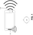
- FIG. 1 is an example of a mobile device 100 with non-ideal audio rendering, in accordance with some embodiments.
- the mobile device 100 includes a left speaker 110L (or 110 L ) and a right speaker 110R (or 110 R ).
- the speakers 110L and 110R are mismatched.
- the speaker 110L may be an earpiece driver with significant low frequency attenuation below 1000 Hz.
- the speaker 110R may be a "broad-band" micro-loudspeaker capable of rendering low and mid-frequency energy below 550 to 1000 Hz.
- the speaker 110R has more output power than the speaker 110L, and is orthogonally firing with respect to the speaker 110L.
- the speakers 110L and 110R may be mismatched with respect to the listener 140 in terms of frequency response, output power, directionality, or any combination thereof.
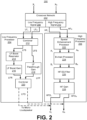
- the audio processing system 200 includes a crossover network 202 that is coupled to a low frequency processor 204 and a high frequency processor 206.
- the crossover network 202 receives the left input channel XL and right input channel XR, and creates low frequency and high frequency channels.
- the crossover network 202 includes filters that create low frequency (LF) channels including a left channel LFL (or LF L ) and a right channel LFR (or LF R ), and high frequency (HF) channels including a left channel HFL (or HF L ), and a right channel HFR (or HF R ).
- the left channel LFL is generated from the low frequency portions of the left input channel OL
- a right channel LFR is generated from the low frequency portions of the right input channel OR.
- the left channel LFL and the right channel LFR collectively form a low frequency signal 208.
- the left channel HFL and the right channel HFR collectively form a high frequency signal 210.
- the low frequency signal 208 is processed by the low frequency processor 204, and the high frequency signal 210 is processed by the high frequency processor 206.
- the audio processing system 200 treats the low frequency signal 208 independently from and in parallel to the counterpart high frequency signal 210.
- the ability of the listener 140 to perceive the device 100 as rendering a spatially immersive sound field from the vantage of a "sweet spot" depends on the treatment of the mid and high frequency audio bands, where both speakers 110 L and 110 R can be employed in combination.
- the high frequency processor 206 performs subband spatial enhancement, b-chain processing, equalization filtering, and amplification on the high frequency signal 210.
- the high frequency processor 206 includes a spatial enhancement processor 222, a b-chain processor 224, a high frequency (HF) equalization (EQ) filter 226, and a high frequency gain 228.
- the spatial enhancement processor 222 receives the left channel HF L and the right channel HF R , and processes these channels to generate a spatially enhanced signal A including a left spatially enhanced channel A L and a right spatially enhanced channel A R .
- the spatial enhancement processor 222 applies a subband spatial processing that includes gain adjusting mid and side subband components of the high frequency signal 208 (including the left channel HF L and the right channel HF R ).
- the spatial enhancement processor 222 may further perform a crosstalk compensation and a crosstalk cancellation. Additional details regarding the spatial enhancement processor 222 are discussed below in connection with FIGS. 3 , 4 , 5 and 6 .
- the HF EQ filter 226 is coupled to the b-chain processor 224.
- the HF EQ filter 226 receives the left channel B L and a right channel B R , and adjusts the relative level and frequency response of the left channel B L and the right channel B R .
- the HF EQ filter 226 can be used to provide additional flexibility in balancing the mix between the high and low frequency signals.
- the HF EQ filter 226 is omitted.
- the functionality of the HF EQ filter 226 is integrated with the b-chain processor 224.
- the N-band parametric EQ 702 may be configured to perform the functionality of the HF EQ filter 226.
- the HF gain 228 is coupled to the HF EQ filter 226.
- the HF gain 228 receives the output of the HF EQ filter 226, and adjusts the overall signal level of the high frequency signal relative to the low frequency signal and its signal path through the low frequency processor 204. In some embodiments, different gains are applied to the left channel and the right channel of the high frequency signal by the HF gain 228.
- the output of the HF gain 228 represents the output of the high frequency processor 206, and includes a left high frequency output channel HFO L and a right high frequency output channel HFO R .
- the left channel HFO L and the right channel HFO R represent a spatially-enhanced transaural image that is combined with the low frequency signal 208 subsequent to processing by the low frequency processor 204.
- the low frequency processor 204 provides a stable non-spatial image (e.g., centerpanned elements) and sufficient punch and body to the perceived overall sound field while avoiding excessive low frequency energy that may degrade and mask the effects of the spatially-enhanced transaural image.
- the low frequency processor 204 includes a combiner 212, a low frequency (LF) boost resonator 214, an LF boost gain 216, a LF passthrough gain 218, and a combiner 220.
- the combiner 212 is coupled to the crossover network 202 and receives the left channel LF L and the right channel LF R .
- the combiner 212 is further coupled to the LF boost resonator 214 and the LF passthrough gain 218.
- the LF boost resonator 214 is coupled to the LF boost gain 216.
- the LF boost gain 216 and LF passthrough gain 218 are coupled to the combiner 220.
- FIG. 3 is a schematic block diagram of a spatial enhancement processor 222, in accordance with some embodiments.
- the spatial enhancement processor 222 spatially enhances an input audio signal, and performing crosstalk cancellation on spatially enhanced audio signal. To that end, the spatial enhancement processor 222 receives the high frequency signal 210 including the left high frequency channel HFL and the right high frequency channel HFR.
- the spatial enhancement processor 222 generates the spatially enhanced signal A including the left spatially enhanced channel A L and the right spatially enhanced channel A R by processing the input channels HF L and HF R .
- the output audio signal A is a spatially enhanced audio signal of the high frequency signal 210 with crosstalk compensation and crosstalk cancellation.
- the spatial enhancement processor 222 may further include an amplifier that amplifies the output audio signal A from the crosstalk cancellation processor 360, and provides the signal A to output devices, such as the loudspeakers 110 L and 110 R , that convert the output channels A L and A R into sound.
- the spatial enhancement processor 222 includes a subband spatial processor 305, a crosstalk compensation processor 340, a combiner 350, and a crosstalk cancellation processor 360.
- the spatial enhancement processor 222 performs crosstalk compensation and subband spatial processing of the input channels HF L and HF R , combines the result of the subband spatial processing with the result of the crosstalk compensation, and then performs a crosstalk cancellation on the combined signals.
- the nonspatial component X m can be generated based on a sum of the left input channel HF L and the right input channel HF R .
- the spatial frequency band divider 310 provides the spatial component X s and the nonspatial component X m to the spatial frequency band processor 320.
- the spatial frequency band processor 320 is coupled to the spatial frequency band divider 310 and the spatial frequency band combiner 330.
- the spatial frequency band processor 320 receives the spatial component X s and the nonspatial component X m from spatial frequency band divider 310, and enhances the received signals.
- the spatial frequency band processor 320 generates an enhanced spatial component E s from the spatial component X s , and an enhanced nonspatial component E m from the nonspatial component X m .
- the spatial frequency band processor 320 applies subband gains to the spatial component X s to generate the enhanced spatial component E s , and applies subband gains to the nonspatial component X m to generate the enhanced nonspatial component E m .
- the spatial frequency band processor 320 additionally or alternatively provides subband delays to the spatial component X s to generate the enhanced spatial component E s , and subband delays to the nonspatial component X m to generate the enhanced nonspatial component E m .
- the subband gains and/or delays can be different for the different (e.g., n) subbands of the spatial component X s and the nonspatial component X m , or can be the same (e.g., for two or more subbands).
- the spatial frequency band processor 320 adjusts the gain and/or delays for different subbands of the spatial component X s and the nonspatial component X m with respect to each other to generate the enhanced spatial component E s and the enhanced nonspatial component E m .
- the spatial frequency band processor 320 then provides the enhanced spatial component E s and the enhanced nonspatial component E m to the spatial frequency band combiner 330.
- the spatial frequency band combiner 330 is coupled to the spatial frequency band processor 320, and further coupled to the combiner 350.
- the spatial frequency band combiner 330 receives the enhanced spatial component Es and the enhanced nonspatial component Em from the spatial frequency band processor 320, and combines the enhanced spatial component Es and the enhanced nonspatial component Em into a left enhanced channel EL (or E L ) and a right enhanced channel ER (or E R ).
- the left enhanced channel EL can be generated based on a sum of the enhanced spatial component Es and the enhanced nonspatial component Em
- the right enhanced channel ER can be generated based on a difference between the enhanced nonspatial component Em and the enhanced spatial component Es.
- the spatial frequency band combiner 330 provides the left enhanced channel EL and the right enhanced channel ER to the combiner 350.
- the crosstalk compensation processor 340 performs a crosstalk compensation to compensate for spectral defects or artifacts in the crosstalk cancellation.
- the crosstalk compensation processor 340 receives the input channels HFL and HFR, and performs a processing to compensate for any artifacts in a subsequent crosstalk cancellation of the enhanced nonspatial component Em and the enhanced spatial component Es performed by the crosstalk cancellation processor 360.
- the crosstalk compensation processor 340 may perform an enhancement on the nonspatial component Xm and the spatial component Xs by applying filters to generate a crosstalk compensation signal Z, including a left crosstalk compensation channel ZL (or Z L ) and a right crosstalk compensation channel ZR (or Z R ).
- the crosstalk compensation processor 340 may perform an enhancement on only the nonspatial component Xm.
- the combiner 350 combines the left enhanced channel EL with the left crosstalk compensation channel ZL to generate a left enhanced compensation channel TL (or T L ), and combines the right enhanced channel ER with the right crosstalk compensation channel ZR to generate a right enhanced compensation channel TR (or T R ).
- the combiner 350 is coupled to the crosstalk cancellation processor 360, and provides the left enhanced compensation channel TL and the right enhanced compensation channel TR to the crosstalk cancellation processor 360.
- the crosstalk cancellation processor 360 receives the left enhanced compensated channel TL and the right enhanced compensation channel TR, and performs crosstalk cancellation on the channels TL, TR to generate the spatially enhanced signal A including the left spatially enhanced channel AL (or A L ) and the right spatially enhanced channel AR (or A R ).
- subband spatial processor 305 Additional details regarding the subband spatial processor 305 are discussed below in connection with FIG. 4 , additional details regarding the crosstalk compensation processor 340 are discussed below in connection with FIG. 5 , and additional details regarding the crosstalk cancellation processor 360 are discussed below in connection with FIG. 6 .
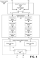
- FIG. 4 is a schematic block diagram of a subband spatial processor 305, in accordance with some embodiments.
- the subband spatial processor 305 includes the spatial frequency band divider 310, the spatial frequency band processor 320, and the spatial frequency band combiner 330.
- the spatial frequency band divider 310 is coupled to the spatial frequency band processor 320, and the spatial frequency band processor 320 is coupled to the spatial frequency band combiner 330.
- the spatial frequency band divider 310 includes an L/R to M/S converter 402 that receives the left input channel HFL and a right input channel HFR, and converts these inputs into the spatial component Xs and the nonspatial component Xm.
- the spatial component Xs may be generated by subtracting the left input channel XL and right input channel XR.
- the nonspatial component Xm may be generated by adding the left input channel XL and the right input channel XR.
- the spatial frequency band processor 320 includes a subband filter for each of n frequency subbands of the nonspatial component Xm and a subband filter for each of the n frequency subbands of the spatial component Xs.
- the spatial frequency band processor 320 includes a series of subband filters for the nonspatial component Xm including a mid-equalization (EQ) filter 404(1) for the subband (1), a mid EQ filter 404(2) for the subband (2), a mid EQ filter 404(3) for the subband (3), and a mid EQ filter 404(4) for the subband (4).
- Each mid EQ filter 404 applies a filter to a frequency subband portion of the nonspatial component Xm to generate the enhanced nonspatial component Em.
- the spatial frequency band processor 320 further includes a series of subband filters for the frequency subbands of the spatial component Xs, including a side equalization (EQ) filter 406(1) for the subband (1), a side EQ filter 406(2) for the subband (2), a side EQ filter 406(3) for the subband (3), and a side EQ filter 406(4) for the subband (4).
- Each side EQ filter 406 applies a filter to a frequency subband portion of the spatial component Xs to generate the enhanced spatial component Es.
- Each of the n frequency subbands of the nonspatial component Xm and the spatial component Xs may correspond with a range of frequencies.
- the frequency subband (1) may corresponding to 0 to 300 Hz
- the frequency subband(2) may correspond to 300 to 510 Hz
- the frequency subband(3) may correspond to 510 to 2700 Hz
- the frequency subband(4) may correspond to 2700 Hz to Nyquist frequency.
- the n frequency subbands are a consolidated set of critical bands.
- the critical bands may be determined using a corpus of audio samples from a wide variety of musical genres. A long term average energy ratio of mid to side components over the 24 Bark scale critical bands is determined from the samples. Contiguous frequency bands with similar long term average ratios are then grouped together to form the set of critical bands.
- the range of the frequency subbands, as well as the number of frequency subbands, may be adjustable.
- the biquad can then be used to implement any second-order filter with real-valued inputs and outputs.
- a discrete-time filter a continuous-time filter is designed and transformed it into discrete time via a bilinear transform. Furthermore, compensation for any resulting shifts in center frequency and bandwidth may be achieved using frequency warping.
- the spatial frequency band combiner 330 receives mid and side components, applies gains to each of the components, and converts the mid and side components into left and right channels.
- the spatial frequency band combiner 330 receives the enhanced nonspatial component Em and the enhanced spatial component Es, and performs global mid and side gains before converting the enhanced nonspatial component Em and the enhanced spatial component Es into the left spatially enhanced channel EL and the right spatially enhanced channel ER.
- the spatial frequency band combiner 330 includes a global mid gain 408, a global side gain 410, and an M/S to L/R converter 412 coupled to the global mid gain 408 and the global side gain 410.
- the global mid gain 408 receives the enhanced nonspatial component Em and applies a gain
- the global side gain 410 receives the enhanced spatial component Es and applies a gain.
- the M/S to L/R converter 412 receives the enhanced nonspatial component Em from the global mid gain 408 and the enhanced spatial component Es from the global side gain 410, and converts these inputs into the left enhanced channel EL and the right enhanced channel ER.
- FIG. 5 is a schematic block diagram of a crosstalk compensation processor 340, in accordance with some embodiments.
- the crosstalk compensation processor 340 receives left and right input channels HFL and HFR, and generates left and right output channels by applying a crosstalk compensation on the input channels.
- the crosstalk compensation processor 340 includes a L/R to M/S converter 502, a mid-component processor 520, a side component processor 530, and an M/S to L/R converter 514.
- the crosstalk compensation processor 340 receives the input channels HFL and HFR, and performs a preprocessing to generate the left crosstalk compensation channel ZL and the right crosstalk compensation channel ZR.
- the channels ZL, ZR may be used to compensate for any artifacts in crosstalk processing, such as crosstalk cancellation or simulation.
- the L/R to M/S converter 502 receives the left channel HFL and the right channel HFR, and generates the nonspatial component Xm and the spatial component Xs of the input channels XL, XR.
- the left and right channels may be summed to generate the nonspatial component of the left and right channels, and subtracted to generate the spatial component of the left and right channels.
- the mid component processor 520 includes a plurality of filters 540, such as m mid filters 540(a), 540(b), through 540(m).
- each of the m mid filters 540 processes one of m frequency bands of the nonspatial component Xm and the spatial component Xs.
- the mid component processor 520 generates a mid-crosstalk compensation channel Zm by processing the nonspatial component Xm.
- the mid filters 540 are configured using a frequency response plot of the nonspatial component Xm with crosstalk processing through simulation.
- any spectral defects such as peaks or troughs in the frequency response plot over a predetermined threshold (e.g., 10 dB) occurring as an artifact of the crosstalk processing can be estimated.
- a predetermined threshold e.g. 10 dB
- the mid crosstalk compensation channel Zm can be generated by the mid component processor 520 to compensate for the estimated peaks or troughs, where each of the m frequency bands corresponds with a peak or trough.
- Each of the mid filters 540 may be configured to adjust for one or more of the peaks and troughs.
- the side component processor 530 includes a plurality of filters 550, such as m side filters 550(a), 550(b) through 550(m).
- the side component processor 530 generates a side crosstalk compensation channel Zs by processing the spatial component Xs.
- a frequency response plot of the spatial component Xs with crosstalk processing can be obtained through simulation.
- any spectral defects such as peaks or troughs in the frequency response plot over a predetermined threshold (e.g., 10 dB) occurring as an artifact of the crosstalk processing can be estimated.
- the side crosstalk compensation channel Zs can be generated by the side component processor 530 to compensate for the estimated peaks or troughs.
- Each of the side filters 550 may be configured to adjust for one or more of the peaks and troughs.
- the mid component processor 520 and the side component processor 530 may include a different number of filters.
- the biquad can then be used to implement a second-order filter with real-valued inputs and outputs.
- a discrete-time filter a continuous-time filter is designed, and then transformed into discrete time via a bilinear transform. Furthermore, resulting shifts in center frequency and bandwidth may be compensated using frequency warping.
- the M/S to L/R converter 514 receives the mid crosstalk compensation channel Zm (or Z m ) and the side crosstalk compensation channel Zs (or Z s ), and generates the left crosstalk compensation channel ZL (or Z L ) and the right crosstalk compensation channel ZR (or Z R ).
- the mid and side channels may be summed to generate the left channel of the mid and side components, and the mid and side channels may be subtracted to generate right channel of the mid and side components.
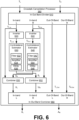
- FIG. 6 is a schematic block diagram of a crosstalk cancellation processor 360, in accordance with some embodiments.
- the crosstalk cancellation processor 360 receives the left enhanced compensation channel TL (or T L ) and the right enhanced compensation channel TR (or T R ) from the combiner 350, and performs crosstalk cancellation on the channels TL, TR to generate the left output channel AL (or A L ), and the right output channel AR (or A R ).
- the crosstalk cancellation processor 360 includes an in-out band divider 610, inverters 620 and 622, contralateral estimators 630 and 640, combiners 650 and 652, and an in-out band combiner 660. These components operate together to divide the input channels TL, TR into in-band components and out-of-band components, and perform a crosstalk cancellation on the in-band components to generate the output channels AL, AR.
- crosstalk cancellation can be performed for a particular frequency band while obviating degradations in other frequency bands. If crosstalk cancellation is performed without dividing the input audio signal T into different frequency bands, the audio signal after such crosstalk cancellation may exhibit significant attenuation or amplification in the nonspatial and spatial components in low frequency (e.g., below 350 Hz), higher frequency (e.g., above 12000 Hz), or both.
- the in-out band divider 610 separates the input channels TL, TR into in-band channels TL,In, TR,In (or T L,In , T R,In ) and out of band channels TL,Out, TR,Out (or T L,Out , T R,Out ), respectively.
- the in-out band divider 610 divides the left enhanced compensation channel TL into a left in-band channel TL,In and a left out-of-band channel TL,Out.
- the in-out band divider 610 separates the right enhanced compensation channel TR into a right in-band channel TR,In and a right out-of-band channel TR,Out.
- Each in-band channel may encompass a portion of a respective input channel corresponding to a frequency range including, for example, 250 Hz to 14 kHz.
- the range of frequency bands may be adjustable, for example according to speaker parameters.
- the inverter 620 and the contralateral estimator 630 operate together to generate a left contralateral cancellation component SL to compensate for a contralateral sound component due to the left in-band channel TL,In.
- the inverter 622 and the contralateral estimator 640 operate together to generate a right contralateral cancellation component SR to compensate for a contralateral sound component due to the right in-band channel TR,In.
- the inverter 620 receives the in-band channel TL,In and inverts a polarity of the received in-band channel TL,In to generate an inverted in-band channel TL,In'.
- the contralateral estimator 630 receives the inverted in-band channel TL,In' (or T L,In '), and extracts a portion of the inverted in-band channel TL,In' corresponding to a contralateral sound component through filtering. Because the filtering is performed on the inverted in-band channel TL,In', the portion extracted by the contralateral estimator 630 becomes an inverse of a portion of the in-band channel TL,In attributing to the contralateral sound component.
- the portion extracted by the contralateral estimator 630 becomes a left contralateral cancellation component SL, which can be added to a counterpart in-band channel TR,In to reduce the contralateral sound component due to the in-band channel TL,In.
- the inverter 620 and the contralateral estimator 630 are implemented in a different sequence.
- the inverter 622 and the contralateral estimator 640 perform similar operations with respect to the in-band channel TR,In to generate the right contralateral cancellation component SR. Therefore, detailed description thereof is omitted herein for the sake of brevity.
- the contralateral estimator 630 includes a filter 632, an amplifier 634, and a delay unit 636.
- the filter 632 receives the inverted input channel TL,In' and extracts a portion of the inverted in-band channel TL,In' corresponding to a contralateral sound component through a filtering function.
- An example filter implementation is a Notch or Highshelf filter with a center frequency selected between 5000 and 10000 Hz, and Q selected between 0.5 and 1.0.
- the configurations of the crosstalk cancellation can be determined by the speaker parameters.
- filter center frequency, delay amount, amplifier gain, and filter gain can be determined, according to an angle formed between two speakers 110L and 110R with respect to a listener.
- values between the speaker angles are used to interpolate other values.
- the combiner 650 combines the right contralateral cancellation component SR to the left in-band channel TL,In to generate a left in-band compensation channel UL, and the combiner 652 combines the left contralateral cancellation component SL to the right in-band channel TR,In to generate a right in-band compensation channel UR.
- the in-out band combiner 660 combines the left in-band compensation channel UL with the out-of-band channel TL,Out to generate the left output channel AL, and combines the right in-band compensation channel UR with the out-of-band channel TR,Out to generate the right output channel AR.
- the left output channel AL includes the right contralateral cancellation component SR corresponding to an inverse of a portion of the in-band channel TR,In attributing to the contralateral sound
- the right output channel AR includes the left contralateral cancellation component SL corresponding to an inverse of a portion of the in-band channel TL,In attributing to the contralateral sound.
- a wavefront of an ipsilateral sound component output by the speaker 110R according to the right output channel AR arrived at the right ear can cancel a wavefront of a contralateral sound component output by the loudspeaker 110 L according to the left output channel AL.
- a wavefront of an ipsilateral sound component output by the speaker 110L according to the left output channel AL arrived at the left ear can cancel a wavefront of a contralateral sound component output by the speaker 110 R according to right output channel AR.
- contralateral sound components can be reduced to enhance spatial detectability.
- FIG. 7 is a schematic block diagram of a b-chain processor 224, in accordance with some embodiments.
- the b-chain processor 224 includes the speaker matching processor 740 and the delay and gain processor 750.
- the speaker matching processor 250 includes an N-band equalizer (EQ) 702 coupled to a left amplifier 704 and a right amplifier 706.
- the delay and gain processor 750 includes a left delay 708 coupled to a left amplifier 712, and a right delay 710 coupled to a right amplifier 714.
- the transformational relationship between the ideal and real rendered spatial image can be described based on (a) overall time delay between one speaker and the listener 140 being different from that of another speaker, (b) signal level (perceived and objective) between one speaker and the listener 140 being different from that of another speaker, and (c) frequency response between one speaker and the listener 140 being different from that of another speaker.
- the b-chain processor 224 corrects the above relative differences in delay, signal level, and frequency response, resulting in a restored near-ideal spatial image, as if the listener 140 (e.g., head position) and/or rendering system were ideally configured.
- the b-chain processor 224 receives as input the audio signal A including the left enhanced channel A L and the right enhanced channel A R from the spatial enhancement processor 222. If the audio signal A has no spatial asymmetries and if no other irregularities exist in the system, the spatial enhancement processor 222 provides a dramatically enhanced sound stage for the listener 140. However, if asymmetries do exist in the system, as illustrated by the mismatched speakers 110 L and 110 R in FIG. 1 , the b-chain processor 224 may be applied to retain the enhanced sound stage under non-ideal conditions.
- Mobile devices may include a front facing earpiece loudspeaker with limited bandwidth (e.g. 1000 - 8000 Hz frequency response), and an orthogonally (down or side-ward) facing micro-loudspeaker (e.g., 200 - 20000 Hz frequency response).
- the speaker system is unmatched in a two-fold manner, with audio driver performance characteristics (e.g., signal level, frequency response, etc.) being different, and time alignment relative to the "ideal" listener position being un-matched because the non-parallel orientation of the speakers.
- audio driver performance characteristics e.g., signal level, frequency response, etc.
- time alignment relative to the "ideal" listener position being un-matched because the non-parallel orientation of the speakers.
- Another example is where a listener using a stereo desktop loudspeaker system does not arrange either the loudspeakers or themselves in the ideal configuration.
- the b-chain processor 224 thus provides for tuning of the characteristics of each channel, addressing associated system-specific asymmetries, resulting in a more perceptually compelling transaural sound stage.
- the speaker matching processor 740 After spatial enhancement processing or some other processing has been applied to the stereo input signal X, tuned under the assumption of an ideally configured system (i.e. listener in sweet spot, matched, symmetrically placed loudspeakers, etc.), the speaker matching processor 740 provides practical loudspeaker balancing for devices that do not provide matched speaker pairs, as is the case in the vast majority of mobile devices.
- the N-band parametric EQ 702 of the speaker matching processor 740 receives the left enhanced channel A L and the right enhanced channel A R , and applies an equalization to each of the channels A L and A R .
- the N-band EQ 702 provides various EQ filter types such as a low and high-shelf filter, a band-pass filter, a band-stop filter, and peak-notch filter, or low and high pass filter. If one loudspeaker in a stereo pair is angled away from the ideal listener sweet spot, for example, that loudspeaker will exhibit noticeable high-frequency attenuation from the listener sweet spot. One or more bands of the N-band EQ 702 can be applied on that loudspeaker channel in order to restore the high frequency energy when observed from the sweet spot (e.g., via high-shelf filter), achieving a near-match to the characteristics of the other forward facing loudspeaker.
- EQ filter types such as a low and high-shelf filter, a band-pass filter, a band-stop filter, and peak-notch filter, or low and high pass filter.
- the N-band EQ 702 includes a filter for each of n bands that are processed independently. The number of bands may vary. In some embodiments, the number of bands correspond with the subbands of the subband spatial processing.
Landscapes
- Engineering & Computer Science (AREA)
- Physics & Mathematics (AREA)
- Signal Processing (AREA)
- Acoustics & Sound (AREA)
- Multimedia (AREA)
- General Engineering & Computer Science (AREA)
- Theoretical Computer Science (AREA)
- Computer Hardware Design (AREA)
- Human Computer Interaction (AREA)
- General Physics & Mathematics (AREA)
- Computer Networks & Wireless Communication (AREA)
- Stereophonic System (AREA)
- Circuit For Audible Band Transducer (AREA)
Claims (15)
- System (200) zum Verarbeiten eines Eingangsaudiosignals mit einem linken Eingangskanal und einem rechten Eingangskanal, wobei das System Folgendes umfasst:ein Crossover-Netzwerk (202), konfiguriert zum Trennen (805) des Eingangsaudiosignals in ein Niederfrequenzsignal (208) und ein Hochfrequenzsignal (210);einen Hochfrequenzprozessor (206), konfiguriert zum Anwenden (815) einer b-Ketten-Verarbeitung auf das Hochfrequenzsignal (210) zum Erzeugen eines Hochfrequenzausgangssignals, wobei die b-Ketten-Verarbeitung das Ausgleichen einer Asymmetrie zwischen einem linken Lautsprecher (110L) und einem rechten Lautsprecher (110R) in mindestens einem von einem Frequenzgang, einer Zeitabstimmung und einem Signalpegel umfasst;einen Niederfrequenzprozessor (204), konfiguriert zum:Anwenden (825) eines parametrisches Bandpassfilters und einer ersten Verstärkung auf das Niederfrequenzsignal (208) zum Erzeugen eines Niederfrequenzresonatorsignals,Anwenden (830) einer zweiten Verstärkung auf das Niederfrequenzsignal zum Erzeugen eines Niederfrequenz-Durchgangssignals, undErzeugen (835) eines Niederfrequenz-Ausgangssignals durch Kombinieren des Niederfrequenz-Resonatorsignals mit dem NiederfrequenzDurchgangssignal; undeinen Kombinierer (220), konfiguriert zum Erzeugen eines Ausgangssignals mit einem linken Kanal des Hochfrequenz-Ausgangssignals für den linken Lautsprecher und einem rechten Kanal des Hochfrequenz-Ausgangssignals für den rechten Lautsprecher, wobei der Kombinierer ferner zum Kombinieren (840) des Niederfrequenz-Ausgangssignals mit dem linken Kanal des Hochfrequenz-Ausgangssignals für den linken Lautsprecher oder dem rechten Kanal des Hochfrequenz-Ausgangssignals für den rechten Lautsprecher konfiguriert ist.
- System nach Anspruch 1, wobei die Konfiguration des Hochfrequenzprozessors (206) zum Anwenden (815) der b-Ketten-Verarbeitung ferner die Konfiguration des Hochfrequenzprozessors (206) beinhaltet zum:Bestimmen der Asymmetrien zwischen dem linken Lautsprecher (110L) und dem rechten Lautsprecher (110R) im Frequenzgang, der Zeitabstimmung für eine Hörposition und dem Signalpegel für die Hörposition; undErzeugen eines linken Kanals des Hochfrequenz-Ausgangssignals und eines rechten Kanals des Hochfrequenz-Ausgangssignals durch:Anwenden einer N-Band-Entzerrung auf das Hochfrequenzsignal (210) zum Ausgleichen der Asymmetrie im Frequenzgang;Anwenden einer Verzögerung auf das Hochfrequenzsignal (210) zum Ausgleichen der Asymmetrie in der Zeitabstimmung; undAnwenden einer dritten Verstärkung auf das Hochfrequenzsignal (210) zum Ausgleichen der Asymmetrie im Signalpegel.
- System nach Anspruch 2, wobei der Hochfrequenzprozessor (206) ferner konfiguriert ist zum:Anwenden (820) eines Entzerrungsfilters zum Justieren eines linken Kanals des Hochfrequenzsignals (210) relativ zu einem rechten Kanal des Hochfrequenzsignals (210); undAnwenden einer vierten Verstärkung auf den linken Kanal und/oder rechten Kanal des Hochfrequenzsignals (210) zum Justieren des Hochfrequenzsignals (210) relativ zu dem Niederfrequenzsignal (208).
- System nach Anspruch 2, wobei der Hochfrequenzprozessor (206) ferner zum Anwenden (810) einer räumlichen Teilbandverarbeitung auf das Hochfrequenzsignal durch Verstärkungsjustieren der Komponenten des mittleren Teilbands und der Komponenten des seitlichen Teilbands des Hochfrequenzsignals (210) zum Erzeugen eines verbesserten Signals konfiguriert ist.
- System nach Anspruch 4, wobei:das verbesserte Signal einen linken verbesserten Kanal und einen rechten verbesserten Kanal umfasst; unddie Konfiguration des Hochfrequenzprozessors (206) zum Anwenden der parametrischen N-Band-Entzerrung die Konfiguration des Hochfrequenzprozessors (206) zum Anwenden eines oder mehrerer Filter auf den linken verbesserten Kanal und/oder den rechten verbesserten Kanal beinhaltet.
- System nach Anspruch 5, wobei der Hochfrequenzprozessor (206) ferner zum Anwenden einer vierten Verstärkung auf den linken verstärkten Kanal und/oder den rechten verstärkten Kanal zum Ausgleichen der Asymmetrie zwischen dem linken Lautsprecher (110L) und dem rechten Lautsprecher (110R) konfiguriert ist.
- System nach Anspruch 2, wobei die Konfiguration des Hochfrequenzprozessors (206) zum Anwenden der Verzögerung und der dritten Verstärkung auf das Hochfrequenzsignal (210) die Konfiguration des Hochfrequenzprozessors (206) zum Anwenden der Verzögerung auf den linken Kanal des Hochfrequenzsignals oder den rechten Kanal des Hochfrequenzsignals (210) beinhaltet.
- System nach Anspruch 2, wobei die Konfiguration des Hochfrequenzprozessors (206) zum Anwenden der Verzögerung und der dritten Verstärkung auf das Hochfrequenzsignal (210) die Konfiguration des Hochfrequenzprozessors (206) zum Anwenden der dritten Verstärkung auf den linken Kanal des Hochfrequenzsignals oder den rechten Kanal des Hochfrequenzsignals (210) beinhaltet.
- System nach Anspruch 1, wobei der linke Lautsprecher (110L) oder der rechte Lautsprecher (110R) ein Mikrolautsprecher ist, und wobei der parametrische Bandpassfilter das Niederfrequenzsignal (208) gemäß einer Frequenzgangcharakteristik des Mikrolautsprechers justiert.
- System nach Anspruch 1, wobei der parametrische Bandpassfilter einen oder mehrere Teile eines Frequenzspektrums des Niederfrequenzsignals (208) verbessert.
- System nach Anspruch 1, wobei:der linke Lautsprecher (110L) oder der rechte Lautsprecher (110R) ein Ohrhörer-Lautsprecher ist;ein anderer von linkem Lautsprecher (110L) und rechtem Lautsprecher (110R) ein Mikrolautsprecher ist; unddas Niederfrequenz-Ausgangssignal dem Mikrolautsprecher zugeführt wird.
- System nach Anspruch 1, wobei die Asymmetrie mindestens eines von einer Verzögerungsdifferenz, einer Signalpegeldifferenz und einer Frequenzgangdifferenz zwischen dem linken Lautsprecher (110L) und dem rechten Lautsprecher (110R) umfasst.
- Computerimplementiertes Verfahren zum Verarbeiten eines Eingangsaudiosignals mit einem linken Eingangskanal und einem rechten Eingangskanal, wobei das Verfahren Folgendes beinhaltet:Trennen (805) des Eingangsaudiosignals in ein Niederfrequenzsignal (208) und ein Hochfrequenzsignal (210);Anwenden (815) einer b-Ketten-Verarbeitung auf das Hochfrequenzsignal (210) zum Erzeugen eines Hochfrequenzausgangssignals, wobei die b-Ketten-Verarbeitung eine Asymmetrie zwischen einem linken Lautsprecher (110L) und einem rechten Lautsprecher (110R) in mindestens einem von einem Frequenzgang, einer Zeitabstimmung und einem Signalpegel ausgleicht;Anwenden (825) eines parametrischen Bandpassfilters und einer ersten Verstärkung auf das Niederfrequenzsignal (208) zum Erzeugen eines Niederfrequenzresonatorsignals;Anwenden (830) einer zweiten Verstärkung auf das Niederfrequenzsignal zum Erzeugen eines Niederfrequenzdurchgangssignals;Erzeugen (835) eines Niederfrequenzausgangssignals durch Kombinieren des Niederfrequenzresonatorsignals mit dem Niederfrequenzdurchgangssignal; undErzeugen eines Ausgangssignals mit einem linken Kanal des Hochfrequenz-Ausgangssignals für den linken Lautsprecher und einem rechten Kanal des Hochfrequenz-Ausgangssignals für den rechten Lautsprecher, wobei das Erzeugen des Ausgangssignals ferner das Kombinieren des Niederfrequenz-Ausgangssignals mit dem linken Kanal des Hochfrequenz-Ausgangssignals für den linken Lautsprecher oder dem rechten Kanal des Hochfrequenz-Ausgangssignals für den rechten Lautsprecher umfasst.
- Verfahren nach Anspruch 13, das ferner Folgendes durch das Rechensystem beinhaltet:Anwenden eines Entzerrungsfilters zum Justieren eines linken Kanals des Hochfrequenzsignals relativ zu einem rechten Kanal des Hochfrequenzsignals; undAnwenden einer vierten Verstärkung auf das Hochfrequenzsignal zum Justieren des Hochfrequenzsignals relativ zu dem Niederfrequenzsignal.
- Nichtflüchtiges computerlesbares Speichermedium mit Befehlen, die bei Ausführung durch einen Computer den Computer zum Durchführen des Verfahrens nach Anspruch 13 oder 14 veranlassen.
Priority Applications (1)
| Application Number | Priority Date | Filing Date | Title |
|---|---|---|---|
| EP25153534.0A EP4554257A1 (de) | 2017-11-29 | 2018-11-26 | Verbesserte virtuelle stereowiedergabe für unangepasste transaurale lautsprechersysteme |
Applications Claiming Priority (3)
| Application Number | Priority Date | Filing Date | Title |
|---|---|---|---|
| US201762592309P | 2017-11-29 | 2017-11-29 | |
| US16/147,312 US10499153B1 (en) | 2017-11-29 | 2018-09-28 | Enhanced virtual stereo reproduction for unmatched transaural loudspeaker systems |
| PCT/US2018/062489 WO2019108489A1 (en) | 2017-11-29 | 2018-11-26 | Enhanced virtual stereo reproduction for unmatched transaural loudspeaker systems |
Related Child Applications (2)
| Application Number | Title | Priority Date | Filing Date |
|---|---|---|---|
| EP25153534.0A Division EP4554257A1 (de) | 2017-11-29 | 2018-11-26 | Verbesserte virtuelle stereowiedergabe für unangepasste transaurale lautsprechersysteme |
| EP25153534.0A Division-Into EP4554257A1 (de) | 2017-11-29 | 2018-11-26 | Verbesserte virtuelle stereowiedergabe für unangepasste transaurale lautsprechersysteme |
Publications (4)
| Publication Number | Publication Date |
|---|---|
| EP3718318A1 EP3718318A1 (de) | 2020-10-07 |
| EP3718318A4 EP3718318A4 (de) | 2021-08-04 |
| EP3718318B1 true EP3718318B1 (de) | 2025-02-26 |
| EP3718318C0 EP3718318C0 (de) | 2025-02-26 |
Family
ID=66665243
Family Applications (2)
| Application Number | Title | Priority Date | Filing Date |
|---|---|---|---|
| EP18884255.3A Active EP3718318B1 (de) | 2017-11-29 | 2018-11-26 | Verbesserte virtuelle stereowiedergabe für unangepasste transaurale lautsprechersysteme |
| EP25153534.0A Pending EP4554257A1 (de) | 2017-11-29 | 2018-11-26 | Verbesserte virtuelle stereowiedergabe für unangepasste transaurale lautsprechersysteme |
Family Applications After (1)
| Application Number | Title | Priority Date | Filing Date |
|---|---|---|---|
| EP25153534.0A Pending EP4554257A1 (de) | 2017-11-29 | 2018-11-26 | Verbesserte virtuelle stereowiedergabe für unangepasste transaurale lautsprechersysteme |
Country Status (7)
| Country | Link |
|---|---|
| US (2) | US10499153B1 (de) |
| EP (2) | EP3718318B1 (de) |
| JP (2) | JP6834061B2 (de) |
| KR (2) | KR102217085B1 (de) |
| CN (2) | CN113660581B (de) |
| TW (2) | TWI743812B (de) |
| WO (1) | WO2019108489A1 (de) |
Families Citing this family (15)
| Publication number | Priority date | Publication date | Assignee | Title |
|---|---|---|---|---|
| US10524078B2 (en) * | 2017-11-29 | 2019-12-31 | Boomcloud 360, Inc. | Crosstalk cancellation b-chain |
| US10462599B2 (en) * | 2018-03-21 | 2019-10-29 | Sonos, Inc. | Systems and methods of adjusting bass levels of multi-channel audio signals |
| US10575116B2 (en) * | 2018-06-20 | 2020-02-25 | Lg Display Co., Ltd. | Spectral defect compensation for crosstalk processing of spatial audio signals |
| US11425521B2 (en) * | 2018-10-18 | 2022-08-23 | Dts, Inc. | Compensating for binaural loudspeaker directivity |
| TWI819199B (zh) * | 2019-03-08 | 2023-10-21 | 日商優護床股份有限公司 | 移動要照護者的方法 |
| US11432069B2 (en) * | 2019-10-10 | 2022-08-30 | Boomcloud 360, Inc. | Spectrally orthogonal audio component processing |
| EP4085660A4 (de) | 2019-12-30 | 2024-05-22 | Comhear Inc. | Verfahren zum bereitstellen eines räumlichen schallfeldes |
| TWI789592B (zh) * | 2020-05-19 | 2023-01-11 | 華碩電腦股份有限公司 | 手持式電子裝置 |
| CN112351379B (zh) * | 2020-10-28 | 2021-07-30 | 歌尔光学科技有限公司 | 音频组件的控制方法以及智能头戴设备 |
| CN115118901B (zh) * | 2021-03-18 | 2025-10-17 | 海信视像科技股份有限公司 | 显示设备及其音频信号播放方法 |
| EP4327324A4 (de) * | 2021-07-08 | 2025-06-25 | Boomcloud 360, Inc. | Farblose erzeugung von wahrnehmungsgebundenen höhenhinweisen unter verwendung von allpassfilternetzwerken |
| CN114040317B (zh) * | 2021-09-22 | 2024-04-12 | 北京车和家信息技术有限公司 | 音响的声道补偿方法及装置、电子设备和存储介质 |
| CN116301647B (zh) * | 2023-03-24 | 2025-12-23 | 昆仑芯(北京)科技有限公司 | 电子设备、确定存储器访存效率的方法和存储介质 |
| TWI878846B (zh) * | 2023-04-13 | 2025-04-01 | 國立中興大學 | 可產生聲音密集消除區之防竊聽裝置 |
| GB2633770A (en) * | 2023-09-19 | 2025-03-26 | Nokia Technologies Oy | Low frequency sound reproduction |
Family Cites Families (33)
| Publication number | Priority date | Publication date | Assignee | Title |
|---|---|---|---|---|
| US5970152A (en) * | 1996-04-30 | 1999-10-19 | Srs Labs, Inc. | Audio enhancement system for use in a surround sound environment |
| US5930374A (en) * | 1996-10-17 | 1999-07-27 | Aphex Systems, Ltd. | Phase coherent crossover |
| US6285767B1 (en) * | 1998-09-04 | 2001-09-04 | Srs Labs, Inc. | Low-frequency audio enhancement system |
| WO2007106399A2 (en) * | 2006-03-10 | 2007-09-20 | Mh Acoustics, Llc | Noise-reducing directional microphone array |
| CN1937854A (zh) * | 2005-09-22 | 2007-03-28 | 三星电子株式会社 | 用于再现双声道虚拟声音的装置和方法 |
| US20090296959A1 (en) * | 2006-02-07 | 2009-12-03 | Bongiovi Acoustics, Llc | Mismatched speaker systems and methods |
| US8619998B2 (en) * | 2006-08-07 | 2013-12-31 | Creative Technology Ltd | Spatial audio enhancement processing method and apparatus |
| KR100813272B1 (ko) * | 2006-12-20 | 2008-03-13 | 삼성전자주식회사 | 스테레오 스피커를 이용한 저음 보강 장치 및 방법 |
| JP2009044268A (ja) * | 2007-08-06 | 2009-02-26 | Sharp Corp | 音声信号処理装置、音声信号処理方法、音声信号処理プログラム、及び、記録媒体 |
| CN101155440A (zh) * | 2007-09-17 | 2008-04-02 | 昊迪移通(北京)技术有限公司 | 针对双声道音频信号的三维环绕音效技术 |
| WO2009095965A1 (ja) | 2008-01-31 | 2009-08-06 | Mitsubishi Electric Corporation | 帯域分割時間補正信号処理装置 |
| US20100057471A1 (en) | 2008-08-26 | 2010-03-04 | Hongwei Kong | Method and system for processing audio signals via separate input and output processing paths |
| EP2362996B1 (de) * | 2008-11-14 | 2012-10-24 | THAT Corporation | Dynamische volumensteuerung und entsprechendes verfahren |
| US20100303245A1 (en) | 2009-05-29 | 2010-12-02 | Stmicroelectronics, Inc. | Diffusing acoustical crosstalk |
| SG193140A1 (en) | 2010-01-07 | 2013-09-30 | That Corp | Compressor based dynamic bass enhancement with eq |
| EP2798737B1 (de) * | 2011-12-27 | 2018-10-10 | Dts Llc | Bassverstärkungssystem |
| KR101676634B1 (ko) * | 2012-08-31 | 2016-11-16 | 돌비 레버러토리즈 라이쎈싱 코오포레이션 | 오브젝트―기반 오디오를 위한 반사된 사운드 렌더링 |
| TWI673707B (zh) | 2013-07-19 | 2019-10-01 | 瑞典商杜比國際公司 | 將以L<sub>1</sub>個頻道為基礎之輸入聲音訊號產生至L<sub>2</sub>個揚聲器頻道之方法及裝置,以及得到一能量保留混音矩陣之方法及裝置,用以將以輸入頻道為基礎之聲音訊號混音以用於L<sub>1</sub>個聲音頻道至L<sub>2</sub>個揚聲器頻道 |
| KR101815082B1 (ko) * | 2013-09-17 | 2018-01-04 | 주식회사 윌러스표준기술연구소 | 멀티미디어 신호 처리 방법 및 장치 |
| WO2015048551A2 (en) | 2013-09-27 | 2015-04-02 | Sony Computer Entertainment Inc. | Method of improving externalization of virtual surround sound |
| CN104681034A (zh) * | 2013-11-27 | 2015-06-03 | 杜比实验室特许公司 | 音频信号处理 |
| EP3120576B1 (de) * | 2014-03-19 | 2018-09-12 | Cirrus Logic International Semiconductor Limited | Nichtlineare steuerung von lautsprechern |
| CN107148782B (zh) * | 2014-09-26 | 2020-06-05 | 苹果公司 | 用于驱动扬声器阵列的方法和设备以及音频系统 |
| CN104869503B (zh) * | 2015-03-23 | 2019-01-04 | 深圳市冠旭电子股份有限公司 | 一种基于等响曲线的动态低频加强方法及系统 |
| CN106572419B (zh) * | 2015-10-08 | 2018-08-03 | 中国科学院声学研究所 | 一种立体声音效增强系统 |
| KR20180075610A (ko) * | 2015-10-27 | 2018-07-04 | 앰비디오 인코포레이티드 | 사운드 스테이지 향상을 위한 장치 및 방법 |
| BR112018014724B1 (pt) | 2016-01-19 | 2020-11-24 | Boomcloud 360, Inc | Metodo, sistema de processamento de audio e midia legivel por computador nao transitoria configurada para armazenar o metodo |
| FR3049802B1 (fr) * | 2016-04-05 | 2018-03-23 | Pierre Vincent | Procede de diffusion sonore prenant en compte les particularites individuelles |
| GB2549805B (en) * | 2016-04-29 | 2018-10-03 | Cirrus Logic Int Semiconductor Ltd | Audio signals |
| GB2556015B (en) * | 2016-04-29 | 2018-10-17 | Cirrus Logic Int Semiconductor Ltd | Audio Signals |
| CN106060710B (zh) | 2016-06-08 | 2019-01-04 | 维沃移动通信有限公司 | 一种音频输出方法及电子设备 |
| CN106887223A (zh) | 2017-02-22 | 2017-06-23 | 安徽井利电子有限公司 | 一种乐器扬声器用远程智能控制系统 |
| US10524078B2 (en) * | 2017-11-29 | 2019-12-31 | Boomcloud 360, Inc. | Crosstalk cancellation b-chain |
-
2018
- 2018-09-28 US US16/147,312 patent/US10499153B1/en active Active
- 2018-11-26 KR KR1020207018637A patent/KR102217085B1/ko active Active
- 2018-11-26 KR KR1020217004024A patent/KR102346935B1/ko active Active
- 2018-11-26 JP JP2020529289A patent/JP6834061B2/ja active Active
- 2018-11-26 EP EP18884255.3A patent/EP3718318B1/de active Active
- 2018-11-26 CN CN202110836804.5A patent/CN113660581B/zh active Active
- 2018-11-26 CN CN201880077133.5A patent/CN111418219B/zh active Active
- 2018-11-26 WO PCT/US2018/062489 patent/WO2019108489A1/en not_active Ceased
- 2018-11-26 EP EP25153534.0A patent/EP4554257A1/de active Pending
- 2018-11-29 TW TW109117775A patent/TWI743812B/zh active
- 2018-11-29 TW TW107142654A patent/TWI697895B/zh active
-
2019
- 2019-10-01 US US16/590,237 patent/US10951986B2/en active Active
-
2021
- 2021-02-03 JP JP2021016028A patent/JP6877664B2/ja active Active
Also Published As
| Publication number | Publication date |
|---|---|
| US10951986B2 (en) | 2021-03-16 |
| US20200100046A1 (en) | 2020-03-26 |
| EP4554257A1 (de) | 2025-05-14 |
| KR20210019125A (ko) | 2021-02-19 |
| JP2021073817A (ja) | 2021-05-13 |
| CN113660581B (zh) | 2023-04-14 |
| TWI697895B (zh) | 2020-07-01 |
| JP6877664B2 (ja) | 2021-05-26 |
| KR102217085B1 (ko) | 2021-02-17 |
| TWI743812B (zh) | 2021-10-21 |
| CN111418219B (zh) | 2021-08-13 |
| EP3718318A4 (de) | 2021-08-04 |
| JP6834061B2 (ja) | 2021-02-24 |
| EP3718318C0 (de) | 2025-02-26 |
| JP2021505067A (ja) | 2021-02-15 |
| TW201926321A (zh) | 2019-07-01 |
| KR102346935B1 (ko) | 2022-01-03 |
| CN111418219A (zh) | 2020-07-14 |
| US10499153B1 (en) | 2019-12-03 |
| KR20200081514A (ko) | 2020-07-07 |
| TW202044235A (zh) | 2020-12-01 |
| WO2019108489A1 (en) | 2019-06-06 |
| EP3718318A1 (de) | 2020-10-07 |
| CN113660581A (zh) | 2021-11-16 |
Similar Documents
| Publication | Publication Date | Title |
|---|---|---|
| EP3718318B1 (de) | Verbesserte virtuelle stereowiedergabe für unangepasste transaurale lautsprechersysteme | |
| JP7811628B2 (ja) | クロストークプロセッシングb-チェーン | |
| US10764704B2 (en) | Multi-channel subband spatial processing for loudspeakers | |
| EP4496349A2 (de) | Spektralfehlerkompensation für die übersprechverarbeitung von räumlichen audiosignalen | |
| EP3857918A1 (de) | Räumliche übersprechverarbeitung für stereosignal | |
| US11284213B2 (en) | Multi-channel crosstalk processing |
Legal Events
| Date | Code | Title | Description |
|---|---|---|---|
| STAA | Information on the status of an ep patent application or granted ep patent |
Free format text: STATUS: THE INTERNATIONAL PUBLICATION HAS BEEN MADE |
|
| PUAI | Public reference made under article 153(3) epc to a published international application that has entered the european phase |
Free format text: ORIGINAL CODE: 0009012 |
|
| STAA | Information on the status of an ep patent application or granted ep patent |
Free format text: STATUS: REQUEST FOR EXAMINATION WAS MADE |
|
| 17P | Request for examination filed |
Effective date: 20200604 |
|
| AK | Designated contracting states |
Kind code of ref document: A1 Designated state(s): AL AT BE BG CH CY CZ DE DK EE ES FI FR GB GR HR HU IE IS IT LI LT LU LV MC MK MT NL NO PL PT RO RS SE SI SK SM TR |
|
| AX | Request for extension of the european patent |
Extension state: BA ME |
|
| DAV | Request for validation of the european patent (deleted) | ||
| DAX | Request for extension of the european patent (deleted) | ||
| A4 | Supplementary search report drawn up and despatched |
Effective date: 20210702 |
|
| RIC1 | Information provided on ipc code assigned before grant |
Ipc: H04S 7/00 20060101AFI20210628BHEP Ipc: H04S 3/00 20060101ALI20210628BHEP Ipc: H04R 3/04 20060101ALN20210628BHEP Ipc: H04S 1/00 20060101ALN20210628BHEP |
|
| STAA | Information on the status of an ep patent application or granted ep patent |
Free format text: STATUS: EXAMINATION IS IN PROGRESS |
|
| 17Q | First examination report despatched |
Effective date: 20230404 |
|
| GRAP | Despatch of communication of intention to grant a patent |
Free format text: ORIGINAL CODE: EPIDOSNIGR1 |
|
| STAA | Information on the status of an ep patent application or granted ep patent |
Free format text: STATUS: GRANT OF PATENT IS INTENDED |
|
| RIC1 | Information provided on ipc code assigned before grant |
Ipc: H04S 1/00 20060101ALN20241009BHEP Ipc: H04R 3/04 20060101ALN20241009BHEP Ipc: H04S 3/00 20060101ALI20241009BHEP Ipc: H04S 7/00 20060101AFI20241009BHEP |
|
| INTG | Intention to grant announced |
Effective date: 20241021 |
|
| GRAS | Grant fee paid |
Free format text: ORIGINAL CODE: EPIDOSNIGR3 |
|
| GRAA | (expected) grant |
Free format text: ORIGINAL CODE: 0009210 |
|
| STAA | Information on the status of an ep patent application or granted ep patent |
Free format text: STATUS: THE PATENT HAS BEEN GRANTED |
|
| AK | Designated contracting states |
Kind code of ref document: B1 Designated state(s): AL AT BE BG CH CY CZ DE DK EE ES FI FR GB GR HR HU IE IS IT LI LT LU LV MC MK MT NL NO PL PT RO RS SE SI SK SM TR |
|
| REG | Reference to a national code |
Ref country code: GB Ref legal event code: FG4D |
|
| REG | Reference to a national code |
Ref country code: CH Ref legal event code: EP |
|
| REG | Reference to a national code |
Ref country code: DE Ref legal event code: R096 Ref document number: 602018079697 Country of ref document: DE |
|
| REG | Reference to a national code |
Ref country code: IE Ref legal event code: FG4D |
|
| U01 | Request for unitary effect filed |
Effective date: 20250324 |
|
| U07 | Unitary effect registered |
Designated state(s): AT BE BG DE DK EE FI FR IT LT LU LV MT NL PT RO SE SI Effective date: 20250328 |
|
| PG25 | Lapsed in a contracting state [announced via postgrant information from national office to epo] |
Ref country code: RS Free format text: LAPSE BECAUSE OF FAILURE TO SUBMIT A TRANSLATION OF THE DESCRIPTION OR TO PAY THE FEE WITHIN THE PRESCRIBED TIME-LIMIT Effective date: 20250526 |
|
| PG25 | Lapsed in a contracting state [announced via postgrant information from national office to epo] |
Ref country code: PL Free format text: LAPSE BECAUSE OF FAILURE TO SUBMIT A TRANSLATION OF THE DESCRIPTION OR TO PAY THE FEE WITHIN THE PRESCRIBED TIME-LIMIT Effective date: 20250226 |
|
| PG25 | Lapsed in a contracting state [announced via postgrant information from national office to epo] |
Ref country code: ES Free format text: LAPSE BECAUSE OF FAILURE TO SUBMIT A TRANSLATION OF THE DESCRIPTION OR TO PAY THE FEE WITHIN THE PRESCRIBED TIME-LIMIT Effective date: 20250226 |
|
| PG25 | Lapsed in a contracting state [announced via postgrant information from national office to epo] |
Ref country code: IS Free format text: LAPSE BECAUSE OF FAILURE TO SUBMIT A TRANSLATION OF THE DESCRIPTION OR TO PAY THE FEE WITHIN THE PRESCRIBED TIME-LIMIT Effective date: 20250626 Ref country code: NO Free format text: LAPSE BECAUSE OF FAILURE TO SUBMIT A TRANSLATION OF THE DESCRIPTION OR TO PAY THE FEE WITHIN THE PRESCRIBED TIME-LIMIT Effective date: 20250526 |
|
| PG25 | Lapsed in a contracting state [announced via postgrant information from national office to epo] |
Ref country code: HR Free format text: LAPSE BECAUSE OF FAILURE TO SUBMIT A TRANSLATION OF THE DESCRIPTION OR TO PAY THE FEE WITHIN THE PRESCRIBED TIME-LIMIT Effective date: 20250226 |
|
| PG25 | Lapsed in a contracting state [announced via postgrant information from national office to epo] |
Ref country code: GR Free format text: LAPSE BECAUSE OF FAILURE TO SUBMIT A TRANSLATION OF THE DESCRIPTION OR TO PAY THE FEE WITHIN THE PRESCRIBED TIME-LIMIT Effective date: 20250527 |
|
| PG25 | Lapsed in a contracting state [announced via postgrant information from national office to epo] |
Ref country code: SM Free format text: LAPSE BECAUSE OF FAILURE TO SUBMIT A TRANSLATION OF THE DESCRIPTION OR TO PAY THE FEE WITHIN THE PRESCRIBED TIME-LIMIT Effective date: 20250226 |
|
| PG25 | Lapsed in a contracting state [announced via postgrant information from national office to epo] |
Ref country code: CZ Free format text: LAPSE BECAUSE OF FAILURE TO SUBMIT A TRANSLATION OF THE DESCRIPTION OR TO PAY THE FEE WITHIN THE PRESCRIBED TIME-LIMIT Effective date: 20250226 |
|
| PG25 | Lapsed in a contracting state [announced via postgrant information from national office to epo] |
Ref country code: SK Free format text: LAPSE BECAUSE OF FAILURE TO SUBMIT A TRANSLATION OF THE DESCRIPTION OR TO PAY THE FEE WITHIN THE PRESCRIBED TIME-LIMIT Effective date: 20250226 |
|
| U20 | Renewal fee for the european patent with unitary effect paid |
Year of fee payment: 8 Effective date: 20251008 |
|
| PLBE | No opposition filed within time limit |
Free format text: ORIGINAL CODE: 0009261 |
|
| STAA | Information on the status of an ep patent application or granted ep patent |
Free format text: STATUS: NO OPPOSITION FILED WITHIN TIME LIMIT |
|
| PGFP | Annual fee paid to national office [announced via postgrant information from national office to epo] |
Ref country code: GB Payment date: 20251001 Year of fee payment: 8 |
|
| 26N | No opposition filed |
Effective date: 20251127 |